JP4885705B2 - Harness connector - Google Patents

Harness connector Download PDF

Info

Publication number
JP4885705B2
JP4885705B2 JP2006354756A JP2006354756A JP4885705B2 JP 4885705 B2 JP4885705 B2 JP 4885705B2 JP 2006354756 A JP2006354756 A JP 2006354756A JP 2006354756 A JP2006354756 A JP 2006354756A JP 4885705 B2 JP4885705 B2 JP 4885705B2
Authority
JP
Japan
Prior art keywords
wire terminal
holder
electric wire
harness
terminal
Prior art date
Legal status (The legal status is an assumption and is not a legal conclusion. Google has not performed a legal analysis and makes no representation as to the accuracy of the status listed.)
Active
Application number
JP2006354756A
Other languages
Japanese (ja)
Other versions
JP2008166136A (en
JP2008166136A5 (en
Inventor
義和 田中
智和 松本
Current Assignee (The listed assignees may be inaccurate. Google has not performed a legal analysis and makes no representation or warranty as to the accuracy of the list.)
Mitsubishi Cable Industries Ltd
Original Assignee
Mitsubishi Cable Industries Ltd
Priority date (The priority date is an assumption and is not a legal conclusion. Google has not performed a legal analysis and makes no representation as to the accuracy of the date listed.)
Filing date
Publication date
Priority to JP2006354756A priority Critical patent/JP4885705B2/en
Application filed by Mitsubishi Cable Industries Ltd filed Critical Mitsubishi Cable Industries Ltd
Priority to EP07807124.8A priority patent/EP2101376B1/en
Priority to CN200780048301XA priority patent/CN101569065B/en
Priority to US12/520,980 priority patent/US7867001B2/en
Priority to PCT/JP2007/067717 priority patent/WO2008081620A1/en
Priority to KR1020097012789A priority patent/KR101352706B1/en
Publication of JP2008166136A publication Critical patent/JP2008166136A/en
Publication of JP2008166136A5 publication Critical patent/JP2008166136A5/ja
Application granted granted Critical
Publication of JP4885705B2 publication Critical patent/JP4885705B2/en
Active legal-status Critical Current
Anticipated expiration legal-status Critical

Links

Images

Description

本発明は、例えば自動車のハーネス回路に使用するハーネス接続体に関するものである。 The present invention relates to a harness connector used for a harness circuit of an automobile, for example.

自動車のハーネス回路においては、幹線から複数の枝線を分岐する必要が屡々ある。そのために従来では、幹線の一部の被覆を剥ぎ取り、露出した導体に枝線を圧着加工し分岐するスプライスジョイント方式と、幹線の端末部に回路分岐用コネクタを配し、幹線、枝線共に汎用コネクタ及び圧着端子を使用して分岐加工する例えば特許文献1に記載のジョイントコネクタ方式との2通りの方式が多く用いられている。   In an automobile harness circuit, it is often necessary to branch a plurality of branch lines from a trunk line. Therefore, conventionally, a part of the trunk line is stripped, a splice joint method that branches by crimping the branch line to the exposed conductor, and a circuit branch connector is arranged at the terminal part of the trunk line. For example, two types of methods such as a joint connector method described in Patent Document 1 are often used for branching using a general-purpose connector and a crimp terminal.

特開2005−71614号公報JP-A-2005-71614

前者のスプライスジョイント方式では、電線を1〜3本毎に圧着加工しなければならず、それらの加工後の状態では作業性が非常に悪いという問題があり、また製造ライン上で圧着加工することが困難なので、ライン生産には不向きである。   In the former splice joint method, one to three electric wires must be crimped, and there is a problem that workability is very poor in the state after the machining, and crimping is performed on the production line. Is difficult for line production.

そこで、このスプライスジョイント方式の問題点を解決するものとして、後者のジョイントコネクタ方式が開発されている。このジョイントコネクタ方式では、ハーネス製造ライン上でのジョイント加工が可能となるため、スプライスジョイント方式と比較して生産効率が向上し、ハーネス回路の修正にも対応可能である。しかし、コネクタ及び嵌合する相手側汎用コネクタ、バスバー、電線端子などの部品点数が多くなることから、ハーネス回路の組立には時間がかかるのが実状である。   Therefore, the latter joint connector system has been developed as a solution to the problems of the splice joint system. This joint connector method enables joint processing on the harness production line, so that the production efficiency is improved as compared with the splice joint method, and it is possible to cope with the modification of the harness circuit. However, since the number of components such as the connector and the mating general-purpose connector, bus bar, and electric wire terminal to be increased increases, it takes a long time to assemble the harness circuit.

特に、特許文献1に開示されているジョイントコネクタを使用したワイヤハーネスでは、ジョイントコネクタが大きいために、分岐すべき個所で分岐することができない。従って、ジョイントコネクタを収容できるスペースがある個所まで電線を延長しなければならず、ワイヤハーネスの小型化に反している。   In particular, in the wire harness using the joint connector disclosed in Patent Document 1, since the joint connector is large, it cannot be branched at a position to be branched. Therefore, it is necessary to extend the electric wire to a place where there is a space that can accommodate the joint connector, which is against the miniaturization of the wire harness.

つまり、ジョイントコネクタ方式においても、省スペース化、更なる作業性の向上、構造の簡素化、円部の防水化など、解決しなければならない課題が多々ある。   In other words, the joint connector system also has many problems that need to be solved, such as space saving, further improvement of workability, simplification of the structure, and waterproofing of the circular portion.

本発明の目的は、上述の課題を解決し、製造し易くワイヤハーネスの組立性に優れたハーネス接続体を提供することにある。 The objective of this invention is providing the harness connection body which was easy to manufacture and was excellent in the assembly property of a wire harness which solves the above-mentioned subject.

上述の目的を達成するための本発明に係るハーネス接続体の技術的特徴は、複数の電線端子挿入口を有する外部ホルダと、該外部ホルダに設けた入口部から挿入して前記外部ホルダ内で使用し、前記電線端子挿入口と連通する電線端子保持孔を有すると共に、これらの電線端子保持孔と内部で交叉するピン端子挿入孔を有する内部ホルダと、一端に接続部を有すると共に中間部に位置決めのための係止部を有し更に他端に電線を接続し前記接続部を前記電線端子挿入口を経て前記内部ホルダの電線端子保持孔内に挿入する電線端子と、前記外部ホルダの入口部から前記内部ホルダのピン端子挿入孔に挿入することにより前記内部ホルダ内の前記電線端子の接続部の接点に接触し前記電線端子同士を電気接続するピン端子とから成り、前記内部ホルダの電線端子保持孔には前記電線端子を保持する可動の保持板を設け、該保持板に前記電線端子の係止部と係合する係止部を設けたことにある。 Technical characteristics of the harness connector according to the present invention for achieving the above object includes an external holder having a plurality of wire terminal insertion openings, in the insertion to the outer holder from the inlet portion provided in the outer holder And having an electric wire terminal holding hole communicating with the electric wire terminal insertion port, an internal holder having a pin terminal insertion hole intersecting with the electric wire terminal holding hole, and having a connecting portion at one end and an intermediate portion A wire terminal having a locking portion for positioning, further connecting an electric wire to the other end, and inserting the connection portion into the wire terminal holding hole of the internal holder through the wire terminal insertion port, and an inlet of the external holder It becomes a by inserting the pin terminal insertion hole of the inner holder from parts in contact with the contacts of the connecting portion of the wire terminal in the inner holder the wire terminals to each other and a pin terminal electrically connected to the internal The wire terminal holding holes of the holder is provided a holding plate of the movable holding the wire terminal, in providing the locking portion engages the engaging portion of the wire terminal in the holding plate.

本発明に係るハーネス接続体によれば、内部ホルダを外部ホルダ内に入れ、電線端子を外部ホルダの電線端子挿入口を介して内部ホルダに挿入して位置決めし、内部ホルダ内でピン端子により電線端子同士を導通し、電気的接続を行う。また、電線端子の取り外しが可能で、電線端子の再組換えが可能となる。 According to the harness connector according to the present invention, the inner holder is placed in the outer holder, the electric wire terminal is inserted into the inner holder through the electric wire terminal insertion port of the outer holder and positioned, and the electric wire is connected by the pin terminal in the inner holder. Conducts electrical connection between terminals. Moreover, the electric wire terminal can be removed, and the electric wire terminal can be recombined.

更に、小型化によりワイヤハーネス中での設置個所が限定されず、任意の個所に配置することができ、電線を延長しなくとも回路配線を行うことができる。   Furthermore, the installation location in the wire harness is not limited due to the miniaturization, and the wiring harness can be arranged at an arbitrary location, and circuit wiring can be performed without extending the electric wire.

特に、自動車のハーネス回路に使用すれば、従来のジョイント構造よりも格段に接続構造がコンパクトになり、ワイヤハーネス作業時間が短縮化される。   In particular, when used in a harness circuit of an automobile, the connection structure becomes much more compact than the conventional joint structure, and the wire harness working time is shortened.

本発明を図示の実施例に基づいて詳細に説明する。
図1の分解斜視図に示すように、ハーネス接続体は複数の電線端子挿入口1aを有する直方体状の外部ホルダ1と、電線端子保持孔2a、ピン端子挿入孔2bを有する内部ホルダ2と、前端の接続部3aに筒状接点3bを設け、後端に電線4を接続した複数の電線端子3と、棒状のスルーピンタイプのピン端子5と、合成ゴムから成る防水部材6とにより構成されている。
The present invention will be described in detail based on the embodiments shown in the drawings.
As shown in the exploded perspective view of FIG. 1, the harness connection body includes a rectangular parallelepiped external holder 1 having a plurality of wire terminal insertion openings 1a, an internal holder 2 having wire terminal holding holes 2a and pin terminal insertion holes 2b, A cylindrical contact 3b is provided at the front end connecting portion 3a, and a plurality of wire terminals 3 having a wire 4 connected at the rear end, a rod-shaped through pin type pin terminal 5, and a waterproof member 6 made of synthetic rubber. ing.

外部ホルダ1には、左右両側から中央方向に向けて、例えば2個ずつの円形断面を有する電線端子挿入口1aが形成され、その内部に内部ホルダ2を内挿する空間部1bが設けられ、更に例えば下面に内部ホルダ2を挿入するための開口部1cが設けられている。   The outer holder 1 has, for example, two wire terminal insertion openings 1a each having a circular cross section from the left and right sides toward the center, and a space portion 1b into which the inner holder 2 is inserted is provided. Further, for example, an opening 1c for inserting the internal holder 2 is provided on the lower surface.

外部ホルダ1として使用する材料としては、例えば熱可塑性合成樹脂が適用され、中でも熱変形温度が高く、高剛性、電気絶縁特性、機械的特性の点で、ポリブチレンテレフタレート(PBT)やポリプロピレン(PP)などが好適である。また、縦横の大きさは使用する電線4の本数や径などにより適宜決定すればよいが、長さは通常では20mm〜150mm程度である。この外部ホルダ1の製造は、所定の金型を用いて熱可塑性樹脂を射出成形させて製作する方法を採用することが一般的である。   As a material used as the external holder 1, for example, a thermoplastic synthetic resin is applied. Among them, polybutylene terephthalate (PBT) and polypropylene (PP) are used in view of high thermal deformation temperature, high rigidity, electrical insulation characteristics, and mechanical characteristics. And the like are preferred. The vertical and horizontal sizes may be appropriately determined depending on the number and diameter of the electric wires 4 to be used, but the length is usually about 20 mm to 150 mm. The external holder 1 is generally manufactured by adopting a method in which a thermoplastic resin is injection-molded using a predetermined mold.

内部ホルダ2は略直方体の形状とされ、図2の断面図にも示すように、外部ホルダ1の空間部1b内に収納した場合に、電線端子挿入口1aと連通し、電線端子3の接続部3aを挿入する電線端子保持孔2aが水平方向に設けられている。また、この電線端子保持孔2aと内部において交叉するピン端子挿入孔2bは、上下方向に向けて形成されている。なお、2a’は電線端子保持孔2aの挿入側と反対側の開口を示している。各電線端子保持孔2a内の上側には先端部が可動とされる可動保持板2cが形成され、可動保持板2cの下面には電線端子3を位置決めするための係止爪2dが設けられている。   The inner holder 2 has a substantially rectangular parallelepiped shape. As shown in the cross-sectional view of FIG. 2, when the inner holder 2 is housed in the space 1 b of the outer holder 1, the inner holder 2 communicates with the wire terminal insertion port 1 a to connect the wire terminal 3. A wire terminal holding hole 2a for inserting the portion 3a is provided in the horizontal direction. Further, the pin terminal insertion hole 2b that intersects with the electric wire terminal holding hole 2a is formed in the vertical direction. In addition, 2a 'has shown opening of the opposite side to the insertion side of the electric wire terminal holding hole 2a. A movable holding plate 2c whose tip is movable is formed on the upper side of each wire terminal holding hole 2a, and a locking claw 2d for positioning the wire terminal 3 is provided on the lower surface of the movable holding plate 2c. Yes.

また内部ホルダ2には、可動保持板2cを押し上げるために、後述する治具を挿入する溝部2eが、内部ホルダ2の電線端子保持孔2aの両入口側の入口部近傍の両側にそれぞれ設けられている。そして、各可動保持板2cの両側部には操作片2fが側方に突出され、これらの操作片2fは上下の可動保持板2c同士で前後にずれて形成されている。   In addition, the inner holder 2 is provided with grooves 2e for inserting a jig, which will be described later, on both sides in the vicinity of the inlet portions of the electric wire terminal holding holes 2a of the inner holder 2 in order to push up the movable holding plate 2c. ing. The operation pieces 2f project laterally on both sides of each movable holding plate 2c, and these operation pieces 2f are formed so as to be displaced forward and backward between the upper and lower movable holding plates 2c.

更に、内部ホルダ2の下部には防水部材6を係止するための例えば2個の鉤状の係止突起2gが下方に向けて突出されている。内部ホルダ2の外面の片側にリブ2hが形成され、他側にはリブが設けられておらず、外部ホルダ1の内部ホルダ2を挿入する空間部1bには、リブ2hを受け入れる溝部が形成されている。   Further, for example, two hook-shaped locking projections 2g for locking the waterproof member 6 protrude downward from the lower portion of the inner holder 2. A rib 2h is formed on one side of the outer surface of the inner holder 2, and no rib is provided on the other side. A groove portion for receiving the rib 2h is formed in the space 1b into which the inner holder 2 of the outer holder 1 is inserted. ing.

この内部ホルダ2の材料は外部ホルダ1と同等でよく、射出成形により製作することが好ましい。また、内部形状が複雑な場合には、複数個に分割して製作し、使用時に接着したり嵌め合わせて形成することができる。   The material of the inner holder 2 may be the same as that of the outer holder 1 and is preferably manufactured by injection molding. Further, when the internal shape is complicated, it can be divided into a plurality of parts, and can be formed by bonding or fitting at the time of use.

電線端子3は1枚の導電金属板を打抜いて形成されており、前端の舌片状の接続部3aには短円筒状に絞り加工された筒状接点3bが下方に向けて設けられている。更に中間部には、内部ホルダ2の係止爪2dに嵌合するための係止孔3cが設けられ、後端に導体圧着部3d、被覆圧着部3eが設けられている。導体圧着部3dにより電線4の導体が圧着して接続され、電線4には防水のために合成ゴムから成る筒状のシール部材7が挿着され、その一部は固定のために電線被覆と共に被覆圧着部3eにより圧着固定されている。   The electric wire terminal 3 is formed by punching one conductive metal plate, and a cylindrical contact 3b drawn into a short cylindrical shape is provided downward on a tongue-like connecting portion 3a at the front end. Yes. Furthermore, a locking hole 3c for fitting into the locking claw 2d of the internal holder 2 is provided in the intermediate part, and a conductor crimping part 3d and a covering crimping part 3e are provided at the rear end. The conductor of the electric wire 4 is crimped and connected by the conductor crimping portion 3d, and a cylindrical seal member 7 made of synthetic rubber is inserted into the electric wire 4 for waterproofing, and a part thereof is fixed together with the electric wire covering for fixing. It is crimped and fixed by the coated crimping part 3e.

この電線端子3は銅板又は銅合金板から所定の形状に打抜き成形したものに、Sn鍍金をしたもの、又はSn鍍金した銅板又は銅合金板を所定の形状に打抜き成形したものを使用すればよい。材質は強度と導電性の点で黄銅が好ましく、更にはSn鍍金することで耐食性が向上し、かつピン端子5との接点との導電性が得易くなる点で好適である。   The wire terminal 3 may be formed by stamping and molding a copper plate or copper alloy plate into a predetermined shape, or by Sn plating, or by punching and molding a Sn plated copper plate or copper alloy plate into a predetermined shape. . The material is preferably brass in terms of strength and conductivity, and is further preferable in that the corrosion resistance is improved by Sn plating and the conductivity with the contact with the pin terminal 5 is easily obtained.

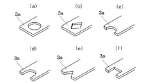
筒状接点3bはピン端子5と接触することで導通する形状であればよく、何れの側からもピン端子5を挿入できるように、筒状接点3bの基部及び先端にテーパ状のガイドを設けることが望ましい。また、接続部3aに設ける接点3bは、実施例のような円筒状でなくとも、図3に示すような(a)円孔状、(b)多角形孔の孔部(c)半円状、(d)U字状、(e)V字状、(f)四角状の切抜きであってもよい。しかし、導電性、接続の持続性等を考慮すると、円筒状、孔状が好ましい。   The cylindrical contact 3b only needs to have a shape that allows electrical conduction when in contact with the pin terminal 5, and a tapered guide is provided at the base and tip of the cylindrical contact 3b so that the pin terminal 5 can be inserted from either side. It is desirable. Further, the contact 3b provided in the connecting portion 3a is not cylindrical as in the embodiment, but (a) a circular hole shape as shown in FIG. 3, (b) a hole portion of a polygonal hole (c) a semicircular shape. , (D) U-shaped, (e) V-shaped, and (f) square cutout. However, in view of conductivity, connection durability, etc., a cylindrical shape and a hole shape are preferable.

電線4は導体の外周に絶縁層を被覆した絶縁電線が適用され、公知の電線径のものが適用できる。導体は従来から自動車ハーネス回路に使用される軟銅線や硬銅線の撚線、又は引張強度を維持し、線径を小さくした例えばCu−Sn合金線などの銅合金線の撚線や単線が適用される。また、絶縁層には従来から公知の絶縁材料が適用され、中でも環境対策としてノンハロゲンの絶縁材料を絶縁層に適用することが環境対策の面で好適である。   As the electric wire 4, an insulated electric wire in which an outer periphery of a conductor is covered with an insulating layer is applied, and those having a known electric wire diameter can be applied. The conductor is a twisted wire or a single wire of a copper alloy wire such as a Cu-Sn alloy wire that maintains a tensile strength and has a small wire diameter, such as a conventional copper wire or a hard copper wire used in an automobile harness circuit. Applied. In addition, conventionally known insulating materials are applied to the insulating layer, and among them, it is preferable to apply a non-halogen insulating material to the insulating layer as an environmental measure.

また、電線4の導体と電線端子3との導体接続は、公知のかしめ、溶接、ハンダ付け、圧着などが適用されるが、導電性、接続性、得られる接続強度の点で、実施例のような導体圧着部3dによる圧着接続が好適である。   The conductor connection between the conductor of the electric wire 4 and the electric wire terminal 3 may be known caulking, welding, soldering, crimping, etc., but in terms of conductivity, connectivity, and connection strength obtained, Such a crimping connection by the conductor crimping part 3d is suitable.

ピン端子5は内部ホルダ2のピン端子挿入孔2bに挿入し、複数の電線端子3の接続部3a同士を導通させるための導電金属製の棒状部材であり、断面形状としては円形、三角形、四角形、多角形などが挙げられる。しかし、製造が容易で、挿入する際に大きな力が必要としない点、かつ安定して確実な導通が得易いということで、断面四角形が好適であり、この場合の電線端子3の接点形状は円筒状又は円孔状が好適である。   The pin terminal 5 is a conductive metal rod-like member that is inserted into the pin terminal insertion hole 2b of the inner holder 2 and electrically connects the connection portions 3a of the plurality of electric wire terminals 3, and has a circular, triangular, or quadrangular cross-sectional shape. And polygons. However, it is easy to manufacture, does not require a large force when inserted, and is easy to obtain stable and reliable conduction, so that a square cross section is preferable. In this case, the contact shape of the wire terminal 3 is A cylindrical shape or a circular hole shape is preferred.

ピン端子5は例えば1枚の導電金属板を折曲して折り畳むことにより、図4に示すような断面略四角形が得られるので、その後に先端部をプレス又は切削などにより錐状とすることができる。このような方法で作製することで、断面積の小さなピン端子5でも、湾曲したり折損することが少なくなる。   For example, the pin terminal 5 is obtained by bending and folding a single conductive metal plate to obtain a substantially rectangular cross section as shown in FIG. it can. By producing by such a method, even the pin terminal 5 having a small cross-sectional area is less likely to be bent or broken.

また、ピン端子5の硬さを接続部3aよりも硬くすることで、電線端子3の接続部3aの側を変形させながら挿入することが好ましい。このピン端子5の硬さ及び接続部3aの硬さは、加工、熱処理や材料の選択で適宜に調整することもできる。更に、筒状接点3bに確実に挿入させる点で、先端部を円錐形、角錐形又は円錐台形、角錐台形などの錐状台形とすることが好適である。   Moreover, it is preferable to insert the pin terminal 5 while deforming the side of the connection part 3a of the wire terminal 3 by making the hardness of the pin terminal 5 harder than that of the connection part 3a. The hardness of the pin terminal 5 and the hardness of the connecting portion 3a can be appropriately adjusted by processing, heat treatment, and material selection. Furthermore, it is preferable that the tip is a conical trapezoidal shape such as a conical shape, a pyramid shape, a truncated cone shape, a truncated pyramid shape, or the like, in order to be surely inserted into the cylindrical contact 3b.

接続部3aの接点が筒形状又は円形状であって、その内径がd1で、ピン端子5の横断面形状を略四角形とし、その対角線の長さをxとすると、d1<xであることが好ましい。また、ピン端子5の横断面を円形状とし、接続部3aの接点を四角形の一辺の長さをd1とした孔部とすることもできる。この場合のピン端子5の円形外径をd2とした場合には、d1<d2であることが好ましい。   When the contact of the connecting portion 3a is cylindrical or circular, the inner diameter is d1, the cross-sectional shape of the pin terminal 5 is substantially square, and the length of the diagonal line is x, d1 <x. preferable. Alternatively, the pin terminal 5 may have a circular cross section, and the contact of the connecting portion 3a may be a hole having a square side of d1 in length. When the circular outer diameter of the pin terminal 5 in this case is d2, it is preferable that d1 <d2.

防水部材6は外部ホルダ1の開口部1cに嵌まり込む直方体とされ、周囲に波形部6aが形成されている。また、防水部材6の上面には内部ホルダ2の係止突起2gが挿入される係止孔6bが設けられている。   The waterproof member 6 is a rectangular parallelepiped that fits into the opening 1c of the external holder 1, and a corrugated portion 6a is formed around it. Further, a locking hole 6 b into which the locking projection 2 g of the internal holder 2 is inserted is provided on the upper surface of the waterproof member 6.

図5は組立状態の断面図を示し、先ず外部ホルダ1の空間部1bに内部ホルダ2を挿入すると、内部ホルダ2は図示しない係合機構により空間部1b内に固定される。この挿入に際しては、前後面で非対称に配置されたリブ2hが空間部1bの溝部に嵌合することにより、挿入方向を誤ることはない。 FIG. 5 shows a sectional view of the assembled state. First, when the internal holder 2 is inserted into the space 1b of the external holder 1, the internal holder 2 is fixed in the space 1b by an engagement mechanism (not shown). At the time of this insertion, the ribs 2h arranged asymmetrically on the front and rear surfaces are fitted into the grooves of the space 1b , so that the insertion direction is not mistaken.

続いて、外部ホルダ1に設けた計4個の電線端子挿入口1aから電線端子3を挿入すると、例えば右上の電線端子3の接続部3aは、内部ホルダ2内にそれぞれ可動保持板2cを押し上げながら挿入される。更に押し込み、係止孔3cに内部ホルダ2の係止爪2dが嵌合すると、右下の電線端子3のように可動保持板2cが元の位置に復元する。これにより、電線端子3は所定位置に位置決めされ、接続部3aの筒状接点3bの中心がピン端子挿入孔2bの中心軸に合致することになる。   Subsequently, when the electric wire terminals 3 are inserted from a total of four electric wire terminal insertion openings 1 a provided in the external holder 1, for example, the connection portion 3 a of the upper right electric wire terminal 3 pushes up the movable holding plate 2 c in the internal holder 2. Inserted. When the locking claw 2d of the inner holder 2 is fitted into the locking hole 3c, the movable holding plate 2c is restored to its original position like the lower right wire terminal 3. Thereby, the electric wire terminal 3 is positioned at a predetermined position, and the center of the cylindrical contact 3b of the connecting portion 3a matches the central axis of the pin terminal insertion hole 2b.

なお実施例では、筒状接点3bが内部ホルダ2の中心で積み重なるために、電線端子挿入口1aは左右で段違いに形成されている。電線端子3が内部ホルダ2内に挿入されると、電線端子3に設けたシール部材7が外部ホルダ1の電線端子挿入口1aの内壁に密着し、外部からの浸水が防止される。   In the embodiment, since the cylindrical contacts 3b are stacked at the center of the inner holder 2, the wire terminal insertion port 1a is formed in a stepped manner on the left and right. When the electric wire terminal 3 is inserted into the inner holder 2, the seal member 7 provided on the electric wire terminal 3 comes into close contact with the inner wall of the electric wire terminal insertion port 1a of the outer holder 1, and water from the outside is prevented.

接続部3aを電線端子挿入口1a内に挿入するに際して、筒状接点3bが上下何れの側を向いているかは重要である。つまり、各接続部3aを任意の向きで挿入すると、内部において整然と所定位置に位置付けすることができなくなるので、電線端子挿入口1aの入口部に筒状接点3bの向きを表示することなどを必要とする場合がある。   When the connecting portion 3a is inserted into the wire terminal insertion port 1a, it is important which side the cylindrical contact 3b is facing. That is, if each connection portion 3a is inserted in an arbitrary direction, it cannot be neatly positioned at a predetermined position inside, so that it is necessary to display the direction of the cylindrical contact 3b at the entrance of the wire terminal insertion port 1a. It may be.

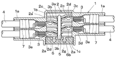
このようにして電線端子3を挿着した後に、図6に示すように、内部ホルダ2のピン端子挿入孔2bに、例えば挿入治具を用いてピン端子5を挿入すると、ピン端子5はそれぞれの電線端子3の筒状接点3bを挿通することにより接触し、各電線端子3同士が導通される。   After inserting the electric wire terminal 3 in this way, as shown in FIG. 6, when the pin terminal 5 is inserted into the pin terminal insertion hole 2b of the internal holder 2 using, for example, an insertion jig, The wire contacts 3 are brought into contact with each other by being inserted through the cylindrical contacts 3b of the wire terminals 3, and the wire terminals 3 are brought into conduction.

更に、防水のために防水部材6を開口部1cに挿入すると、防水部材6の係止孔6bに内部ホルダ2の係止突起2gが嵌入し、防水部材6の脱落が防止され、波形部6aにより外部ホルダ1内に水が浸入することはない。防水部材6による閉止を更に確実にするために、開口部1cの防水部材6の上から合成樹脂製の板体を嵌合することもできる。なお、図7は図6と同じ状態の外部ホルダ1のみを断面とした側面図である。   Further, when the waterproof member 6 is inserted into the opening 1c for waterproofing, the locking protrusion 2g of the internal holder 2 is fitted into the locking hole 6b of the waterproof member 6, and the waterproof member 6 is prevented from falling off, and the corrugated portion 6a. Thus, water does not enter the outer holder 1. In order to further ensure the closing by the waterproof member 6, a plate made of synthetic resin can be fitted over the waterproof member 6 of the opening 1c. FIG. 7 is a side view in which only the outer holder 1 in the same state as FIG.

このような構成の実施例においては、外部ホルダ1の内部には、電線4に装着したシール部材7及び防水部材6により水の浸入が阻止され、このハーネス接続体内を防水構造とすることができる。電線端子3を挿入しない電線端子挿入口1aについては、合成ゴムなどから成る盲栓により封止すれば、内部に水が浸入することはない。なお、防水構造としない場合もあり得るので、この場合にはシール部材7を使用せず、防水部材6の代りに合成樹脂による板体を開口部1cに嵌合すればよい。   In the embodiment having such a configuration, the entry of water is prevented inside the external holder 1 by the seal member 7 and the waterproof member 6 attached to the electric wire 4, and the harness connection body can have a waterproof structure. . If the wire terminal insertion port 1a into which the wire terminal 3 is not inserted is sealed with a blind plug made of synthetic rubber or the like, water does not enter the inside. Note that the waterproof structure may not be provided, and in this case, the sealing member 7 is not used, and a plate made of synthetic resin may be fitted into the opening 1c instead of the waterproof member 6.

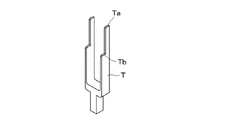
図8は内部ホルダ2の操作片2fを押し上げる治具Tの斜視図を示し、治具Tは2つの端部Ta、Tbを有し、また操作片2fは上下の可動保持板2cで前後にずれているために、これらの操作片2fを治具Tにより同時に操作して、2つの可動保持板2cを同時に押し上げ可能とされている。   FIG. 8 shows a perspective view of a jig T that pushes up the operation piece 2f of the inner holder 2. The jig T has two ends Ta and Tb, and the operation piece 2f is moved back and forth by the upper and lower movable holding plates 2c. Since they are displaced, it is possible to simultaneously push up these two movable holding plates 2c by operating these operation pieces 2f with the jig T at the same time.

図9は内部ホルダ2に対する治具Tの操作説明図であり、外部ホルダ1、電線端子3の図示は省略している。電線端子3を取り外すために可動保持板2cの操作片2fを治具Tを内部ホルダ2の溝部2eから挿入して押し上げる。即ち、回路の組換え等のために、電線端子3を組立体から取り外すには、防水部材6を外してからピン端子5を抜き取り、電線端子3を内部ホルダ2から取り外す必要がある。   FIG. 9 is an explanatory diagram of the operation of the jig T with respect to the inner holder 2, and the illustration of the outer holder 1 and the wire terminal 3 is omitted. In order to remove the wire terminal 3, the operation piece 2 f of the movable holding plate 2 c is pushed up by inserting the jig T from the groove 2 e of the internal holder 2. That is, in order to remove the wire terminal 3 from the assembly for circuit recombination or the like, it is necessary to remove the waterproof member 6 and then remove the pin terminal 5 and remove the wire terminal 3 from the internal holder 2.

開口部1cを介して治具Tの端部Ta、Tbを溝部2eに下方から挿し込み、図9の左側に示すように、上下の可動保持板2cを操作片2fを介して同時に押し上げる。この押し上げにより、電線端子3の係止孔3cから係止爪2dが外れ、電線4を引いて2個の電線端子3を同時に外部に引き出すことができる。残りの2個の電線端子3については、他側の溝部2eに治具Tを挿し込んで同様に引き出せばよい。   The ends Ta and Tb of the jig T are inserted into the groove 2e from below through the opening 1c, and the upper and lower movable holding plates 2c are simultaneously pushed up through the operation piece 2f as shown on the left side of FIG. By this push-up, the locking claw 2d is removed from the locking hole 3c of the electric wire terminal 3, and the electric wire 4 can be pulled to simultaneously pull out the two electric wire terminals 3 to the outside. The remaining two wire terminals 3 may be similarly drawn by inserting the jig T into the groove 2e on the other side.

実施例では、可動保持板2cに係止爪2dを設け、電線端子3に係止孔3cを設けたが、これらを逆にして、可動保持板2cに凹部を設け、電線端子3に凸部を設けるようにしてもよい。また、外部ホルダ1に電線端子挿入口1aを計4個設けて、4個の電線端子3を挿入したが、更に多数或いは少数の電線端子挿入口1aを設けて回路を設計することができる。   In the embodiment, the latching claw 2d is provided on the movable holding plate 2c and the latching hole 3c is provided on the electric wire terminal 3. However, these are reversed, the concave portion is provided on the movable holding plate 2c, and the convex portion is provided on the electric wire terminal 3. May be provided. In addition, a total of four wire terminal insertion openings 1a are provided in the external holder 1 and the four wire terminals 3 are inserted. However, a circuit can be designed by providing a larger or smaller number of wire terminal insertion openings 1a.

実施例のハーネス接続体の分解斜視図である。It is a disassembled perspective view of the harness connection body of an Example. 内部ホルダの断面図である。It is sectional drawing of an internal holder. 電線端子の変形例の斜視図である。It is a perspective view of the modification of an electric wire terminal. ピン端子の断面図である。It is sectional drawing of a pin terminal. 組立時のハーネス接続体の断面図である。It is sectional drawing of the harness connection body at the time of an assembly. 組立後のハーネス接続体の断面図である。It is sectional drawing of the harness connection body after an assembly. 外部ホルダのみを断面としたハーネス接続体の側面図である。It is a side view of the harness connection body which made the external holder only a cross section. 治具の斜視図である。It is a perspective view of a jig. 電線端子を外すための治具の操作説明図である。It is operation explanatory drawing of the jig | tool for removing an electric wire terminal.

符号の説明Explanation of symbols

1 外部ホルダ
1a 電線端子挿入口
1b 空間部
1c 開口部
2 内部ホルダ
2a 電線端子保持孔
2b ピン端子挿入孔
2c 可動保持板
2d 係止爪
2e 溝部
2f 操作片
2h リブ
3 電線端子
3a 接続部
3b 筒状接点
3c 係止孔
3d 導体圧着部
3e 被覆圧着部
4 電線
5 ピン端子
6 防水部材
7 シール部材
DESCRIPTION OF SYMBOLS 1 External holder 1a Electric wire terminal insertion port 1b Space part 1c Opening part 2 Internal holder 2a Electric wire terminal holding hole 2b Pin terminal insertion hole 2c Movable holding plate 2d Locking claw 2e Groove part 2f Operation piece 2h Rib 3 Electric wire terminal 3a Connection part 3b Tube Contact 3c locking hole 3d conductor crimping part 3e covering crimping part 4 electric wire 5 pin terminal 6 waterproofing member 7 sealing member

Claims (5)

複数の電線端子挿入口を有する外部ホルダと、該外部ホルダに設けた入口部から挿入して前記外部ホルダ内で使用し、前記電線端子挿入口と連通する電線端子保持孔を有すると共に、これらの電線端子保持孔と内部で交叉するピン端子挿入孔を有する内部ホルダと、一端に接続部を有すると共に中間部に位置決めのための係止部を有し更に他端に電線を接続し前記接続部を前記電線端子挿入口を経て前記内部ホルダの電線端子保持孔内に挿入する電線端子と、前記外部ホルダの入口部から前記内部ホルダのピン端子挿入孔に挿入することにより前記内部ホルダ内の前記電線端子の接続部の接点に接触し前記電線端子同士を電気接続するピン端子とから成り、前記内部ホルダの電線端子保持孔には前記電線端子を保持する可動の保持板を設け、該保持板に前記電線端子の係止部と係合する係止部を設けたことを特徴とする接続部材を用いたハーネス接続体。 An external holder having a plurality of wire terminal insertion openings, is inserted from an inlet portion provided in the outer holder used within the external holder, together with the wire terminal insertion opening and communicating with the wire terminal holding holes, these An internal holder having a pin terminal insertion hole intersecting with an electric wire terminal holding hole, a connecting portion at one end and a locking portion for positioning at an intermediate portion, and further connecting an electric wire to the other end a wire terminal to be inserted into wire terminal holding hole of the inner holder through the wire terminal insertion openings, said inside the inner holder by inserting the inlet portion of the outer holder to the pin terminal insertion hole of said inner holder It consists of a pin terminal that contacts the contact of the connecting portion of the electric wire terminal and electrically connects the electric wire terminals, and is provided with a movable holding plate that holds the electric wire terminal in the electric wire terminal holding hole of the inner holder, Harness connector using a connecting member, characterized in that a locking portion that engages with the locking portion of the wire terminal to the holding plate. 前記内部ホルダの保持板の側方に操作片を突出し、該操作片を介して前記保持板を動かし、前記保持板の係止部を前記電線端子の係止部から外すことを特徴とする請求項に記載の接続部材を用いたハーネス接続体。 The operation piece protrudes to the side of the holding plate of the inner holder, the holding plate is moved via the operation piece, and the locking portion of the holding plate is detached from the locking portion of the wire terminal. A harness connector using the connection member according to Item 1 . 前記電線端子に設けた係止部を凹部とし、前記内部ホルダに設けた係止部を凸部としたことを特徴とする請求項1又は2に記載の接続部材を用いたハーネス接続体。 The harness connecting body using the connection member according to claim 1 or 2 , wherein the engaging portion provided in the electric wire terminal is a concave portion, and the engaging portion provided in the internal holder is a convex portion. 前記電線にシール部材を挿通し前記外部ホルダの電線端子挿入口と前記電線との間を防水構造とし、前記入口部を防水部材により閉止したことを特徴とする請求項1〜3の何れか1つの請求項に記載の接続部材を用いたハーネス接続体。 Inserting the sealing member to the electric wire and a waterproof structure between the wire terminal insertion opening and said electric wire of said outer holder, any one of the preceding claims, characterized in that the inlet was closed by the waterproof member A harness connection body using the connection member according to claim 1 . 請求項1〜4に記載の接続部材を用いたハーネス接続体を使用したことを特徴とする自動車用ハーネス回路。 Automobile harness circuit, characterized in that using a harness connector using the connection member according to claim 1.
JP2006354756A 2006-12-28 2006-12-28 Harness connector Active JP4885705B2 (en)

Priority Applications (6)

Application Number Priority Date Filing Date Title
JP2006354756A JP4885705B2 (en) 2006-12-28 2006-12-28 Harness connector
CN200780048301XA CN101569065B (en) 2006-12-28 2007-09-12 Connection member and harness connector
US12/520,980 US7867001B2 (en) 2006-12-28 2007-09-12 Connection member and harness connector
PCT/JP2007/067717 WO2008081620A1 (en) 2006-12-28 2007-09-12 Connection member and harness connector
EP07807124.8A EP2101376B1 (en) 2006-12-28 2007-09-12 Connection member and harness connector
KR1020097012789A KR101352706B1 (en) 2006-12-28 2007-09-12 Connection member and harness connector

Applications Claiming Priority (1)

Application Number Priority Date Filing Date Title
JP2006354756A JP4885705B2 (en) 2006-12-28 2006-12-28 Harness connector

Publications (3)

Publication Number Publication Date
JP2008166136A JP2008166136A (en) 2008-07-17
JP2008166136A5 JP2008166136A5 (en) 2010-12-16
JP4885705B2 true JP4885705B2 (en) 2012-02-29

Family

ID=39695322

Family Applications (1)

Application Number Title Priority Date Filing Date
JP2006354756A Active JP4885705B2 (en) 2006-12-28 2006-12-28 Harness connector

Country Status (1)

Country Link
JP (1) JP4885705B2 (en)

Families Citing this family (2)

* Cited by examiner, † Cited by third party
Publication number Priority date Publication date Assignee Title
JP5520565B2 (en) * 2009-10-15 2014-06-11 矢崎総業株式会社 Power interrupting structure and power distributor
JP7473439B2 (en) 2020-09-30 2024-04-23 矢崎総業株式会社 connector

Family Cites Families (5)

* Cited by examiner, † Cited by third party
Publication number Priority date Publication date Assignee Title
JPH0427587A (en) * 1990-05-24 1992-01-30 Dainippon Printing Co Ltd Manufacture of thermal transfer sheet
JP2813716B2 (en) * 1993-02-24 1998-10-22 矢崎総業株式会社 Connector terminal release structure
JP3266064B2 (en) * 1997-09-02 2002-03-18 住友電装株式会社 Continuity connector
JP2005071614A (en) * 2003-08-21 2005-03-17 Ryosei Electro-Circuit Systems Ltd Joint connector
JP2005141954A (en) * 2003-11-04 2005-06-02 Sumitomo Wiring Syst Ltd Waterproof case of joint connector

Also Published As

Publication number Publication date
JP2008166136A (en) 2008-07-17

Similar Documents

Publication Publication Date Title
KR101352706B1 (en) Connection member and harness connector
JP4898296B2 (en) Connecting member
JP4833826B2 (en) Connection member and harness connection body using the member
JP5140407B2 (en) Joint connector
US7883361B2 (en) Connection member and harness connection body using the connection member
JP2013004347A (en) Shield connector
JP5390792B2 (en) Connecting member
JP4885704B2 (en) Harness connector
JP4885705B2 (en) Harness connector
JP2014075245A (en) Electric wire, and connection structure of the same
JP4800066B2 (en) Connecting member
JP2011060426A (en) Connector
JP7144290B2 (en) Terminal connection structure
JP2018181555A (en) Connector
JP4813973B2 (en) Connecting member
JP4695013B2 (en) Waterproof joint connector
JP4933246B2 (en) Connection member and harness connection body using the connection member
JP4898295B2 (en) Connecting member
KR100922154B1 (en) Connector
JP2011060427A (en) Connector
JP2020064751A (en) Terminal structure
JP2000091004A (en) Connector
KR20090105164A (en) Connector

Legal Events

Date Code Title Description
A621 Written request for application examination

Free format text: JAPANESE INTERMEDIATE CODE: A621

Effective date: 20091029

A521 Written amendment

Free format text: JAPANESE INTERMEDIATE CODE: A523

Effective date: 20100225

A521 Written amendment

Free format text: JAPANESE INTERMEDIATE CODE: A523

Effective date: 20101026

A131 Notification of reasons for refusal

Free format text: JAPANESE INTERMEDIATE CODE: A131

Effective date: 20110830

A521 Written amendment

Free format text: JAPANESE INTERMEDIATE CODE: A523

Effective date: 20111007

TRDD Decision of grant or rejection written
A01 Written decision to grant a patent or to grant a registration (utility model)

Free format text: JAPANESE INTERMEDIATE CODE: A01

Effective date: 20111122

A01 Written decision to grant a patent or to grant a registration (utility model)

Free format text: JAPANESE INTERMEDIATE CODE: A01

A61 First payment of annual fees (during grant procedure)

Free format text: JAPANESE INTERMEDIATE CODE: A61

Effective date: 20111208

FPAY Renewal fee payment (event date is renewal date of database)

Free format text: PAYMENT UNTIL: 20141216

Year of fee payment: 3

R150 Certificate of patent or registration of utility model

Ref document number: 4885705

Country of ref document: JP

Free format text: JAPANESE INTERMEDIATE CODE: R150

Free format text: JAPANESE INTERMEDIATE CODE: R150

FPAY Renewal fee payment (event date is renewal date of database)

Free format text: PAYMENT UNTIL: 20141216

Year of fee payment: 3

S111 Request for change of ownership or part of ownership

Free format text: JAPANESE INTERMEDIATE CODE: R313113

FPAY Renewal fee payment (event date is renewal date of database)

Free format text: PAYMENT UNTIL: 20141216

Year of fee payment: 3

R350 Written notification of registration of transfer

Free format text: JAPANESE INTERMEDIATE CODE: R350

S531 Written request for registration of change of domicile

Free format text: JAPANESE INTERMEDIATE CODE: R313531

R350 Written notification of registration of transfer

Free format text: JAPANESE INTERMEDIATE CODE: R350