WO2009142011A1 - 最小送電損失系統構成の決定装置、方法及びプログラム - Google Patents
最小送電損失系統構成の決定装置、方法及びプログラム Download PDFInfo
- Publication number
- WO2009142011A1 WO2009142011A1 PCT/JP2009/002224 JP2009002224W WO2009142011A1 WO 2009142011 A1 WO2009142011 A1 WO 2009142011A1 JP 2009002224 W JP2009002224 W JP 2009002224W WO 2009142011 A1 WO2009142011 A1 WO 2009142011A1
- Authority
- WO
- WIPO (PCT)
- Prior art keywords
- transmission loss
- system configuration
- switch
- minimum
- closed
- Prior art date
- Legal status (The legal status is an assumption and is not a legal conclusion. Google has not performed a legal analysis and makes no representation as to the accuracy of the status listed.)
- Ceased
Links
Images






Classifications
-
- H—ELECTRICITY
- H02—GENERATION; CONVERSION OR DISTRIBUTION OF ELECTRIC POWER
- H02J—ELECTRIC POWER NETWORKS; CIRCUIT ARRANGEMENTS OR SYSTEMS FOR SUPPLYING OR DISTRIBUTING ELECTRIC POWER; SYSTEMS FOR STORING ELECTRIC ENERGY
- H02J3/00—Circuit arrangements for AC mains or AC distribution networks
-
- H—ELECTRICITY
- H02—GENERATION; CONVERSION OR DISTRIBUTION OF ELECTRIC POWER
- H02J—ELECTRIC POWER NETWORKS; CIRCUIT ARRANGEMENTS OR SYSTEMS FOR SUPPLYING OR DISTRIBUTING ELECTRIC POWER; SYSTEMS FOR STORING ELECTRIC ENERGY
- H02J2103/00—Details of circuit arrangements for mains or AC distribution networks
- H02J2103/30—Simulating, planning, modelling, reliability check or computer assisted design [CAD] of electric power networks
-
- Y—GENERAL TAGGING OF NEW TECHNOLOGICAL DEVELOPMENTS; GENERAL TAGGING OF CROSS-SECTIONAL TECHNOLOGIES SPANNING OVER SEVERAL SECTIONS OF THE IPC; TECHNICAL SUBJECTS COVERED BY FORMER USPC CROSS-REFERENCE ART COLLECTIONS [XRACs] AND DIGESTS
- Y02—TECHNOLOGIES OR APPLICATIONS FOR MITIGATION OR ADAPTATION AGAINST CLIMATE CHANGE
- Y02E—REDUCTION OF GREENHOUSE GAS [GHG] EMISSIONS, RELATED TO ENERGY GENERATION, TRANSMISSION OR DISTRIBUTION
- Y02E40/00—Technologies for an efficient electrical power generation, transmission or distribution
- Y02E40/70—Smart grids as climate change mitigation technology in the energy generation sector
-
- Y—GENERAL TAGGING OF NEW TECHNOLOGICAL DEVELOPMENTS; GENERAL TAGGING OF CROSS-SECTIONAL TECHNOLOGIES SPANNING OVER SEVERAL SECTIONS OF THE IPC; TECHNICAL SUBJECTS COVERED BY FORMER USPC CROSS-REFERENCE ART COLLECTIONS [XRACs] AND DIGESTS
- Y02—TECHNOLOGIES OR APPLICATIONS FOR MITIGATION OR ADAPTATION AGAINST CLIMATE CHANGE
- Y02E—REDUCTION OF GREENHOUSE GAS [GHG] EMISSIONS, RELATED TO ENERGY GENERATION, TRANSMISSION OR DISTRIBUTION
- Y02E60/00—Enabling technologies; Technologies with a potential or indirect contribution to GHG emissions mitigation
-
- Y—GENERAL TAGGING OF NEW TECHNOLOGICAL DEVELOPMENTS; GENERAL TAGGING OF CROSS-SECTIONAL TECHNOLOGIES SPANNING OVER SEVERAL SECTIONS OF THE IPC; TECHNICAL SUBJECTS COVERED BY FORMER USPC CROSS-REFERENCE ART COLLECTIONS [XRACs] AND DIGESTS
- Y04—INFORMATION OR COMMUNICATION TECHNOLOGIES HAVING AN IMPACT ON OTHER TECHNOLOGY AREAS
- Y04S—SYSTEMS INTEGRATING TECHNOLOGIES RELATED TO POWER NETWORK OPERATION, COMMUNICATION OR INFORMATION TECHNOLOGIES FOR IMPROVING THE ELECTRICAL POWER GENERATION, TRANSMISSION, DISTRIBUTION, MANAGEMENT OR USAGE, i.e. SMART GRIDS
- Y04S10/00—Systems supporting electrical power generation, transmission or distribution
- Y04S10/50—Systems or methods supporting the power network operation or management, involving a certain degree of interaction with the load-side end user applications
-
- Y—GENERAL TAGGING OF NEW TECHNOLOGICAL DEVELOPMENTS; GENERAL TAGGING OF CROSS-SECTIONAL TECHNOLOGIES SPANNING OVER SEVERAL SECTIONS OF THE IPC; TECHNICAL SUBJECTS COVERED BY FORMER USPC CROSS-REFERENCE ART COLLECTIONS [XRACs] AND DIGESTS
- Y04—INFORMATION OR COMMUNICATION TECHNOLOGIES HAVING AN IMPACT ON OTHER TECHNOLOGY AREAS
- Y04S—SYSTEMS INTEGRATING TECHNOLOGIES RELATED TO POWER NETWORK OPERATION, COMMUNICATION OR INFORMATION TECHNOLOGIES FOR IMPROVING THE ELECTRICAL POWER GENERATION, TRANSMISSION, DISTRIBUTION, MANAGEMENT OR USAGE, i.e. SMART GRIDS
- Y04S40/00—Systems for electrical power generation, transmission, distribution or end-user application management characterised by the use of communication or information technologies, or communication or information technology specific aspects supporting them
- Y04S40/20—Information technology specific aspects, e.g. CAD, simulation, modelling, system security
Definitions
- the present invention relates to an apparatus for determining a transmission loss of a distribution system, and more particularly, to a determination apparatus, a method, and a program for a minimum transmission loss system configuration capable of determining a system configuration that minimizes the transmission loss in a practical calculation time. .
- the method of determining the system configuration that minimizes the transmission loss of the distribution system is as follows: “The distribution system is configured radially and there are capacity constraints on feeders and switches in the system”. Thus, a method for determining the open / close state of a switch provided in the distribution system so that the power transmission loss is minimized is known. An example of a method for determining the distribution system configuration that minimizes the transmission loss of such a distribution system will be described below with reference to FIGS.
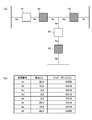
- FIG. 9A is a diagram showing a connection configuration example of a distribution system in which five switches 91 to 95 are radially arranged. Among the blocks indicating the switches, the “open” state blocks are blank. The blocks in the “closed” state are indicated by hatching. That is, in FIG. 9A, the switches 91 and 94 are in the “open” state, and the switches 92, 93, and 95 are in the “closed” state.
- FIG. 9B shows the load and the impedance of the section corresponding to the section numbers 9a to 9g of the distribution system in FIG. 9A.
- the transmission loss in each section is expressed by the following equation (1).
- the transmission loss in each section of the distribution system configured radially as shown in FIG. 9A is obtained by substituting the load and impedance shown in FIG. Can be calculated.
- all the switches 91 to 95 are opened and closed so that the distribution system maintains a radiating state.
- the power transmission loss is calculated with respect to the state, and the switching states of the switches 91 to 95 are determined so that the total loss is minimized.
- FIG. 11 is a diagram showing all combinations of the switching states of the switches in such a radially distributed distribution system. That is, (a) to (h) of FIG. 11 respectively show eight system configurations with different switching states of the switches.
- FIG. 12 shows the result of calculating the power transmission loss corresponding to each system configuration (a) to (h) in FIG. According to FIG. 12, the minimum value of the power transmission loss is the power transmission loss value “56.267W” of the system configuration (f), and it can be seen that this system configuration (f) is a system configuration that minimizes the power transmission loss.
- a branch exchange method has been proposed as one of the system configuration determination methods for minimizing the transmission loss of such a distribution system (see Non-Patent Document 1).
- this branch exchange method in a radial distribution system, a switch in an “open” state is changed to a “closed” state to create one loop, and the power flow calculation of the created loop is performed.
- the system configuration in which the switch having the minimum passing current is set to the “open” state is obtained.
- the system configuration that minimizes the transmission loss is obtained. This is the extraction method.
- a loop is created by closing the switch 91 in the “open” state, and the power flow calculation in this loop is performed.
- the current passing through 91 to 93 and 95 is calculated.
- the passing current of each of the switches 92 to 93, 95 maintaining the “closed” state is to close the switch 91 with respect to the passing current of the system configuration of FIG. 9 in which the switch 91 is in the “open” state.
- the calculation is performed by adding the current flowing through the switch 91.
- the passing current of the switch 91 can be calculated from the potential difference between both ends of the switch 91 in the “open” state in FIG. 9 by using Thevenin's law.
- the potential difference between both ends of the switch 91 can be obtained by calculating the voltage drop Vd [V] in each section by the following equation (2).
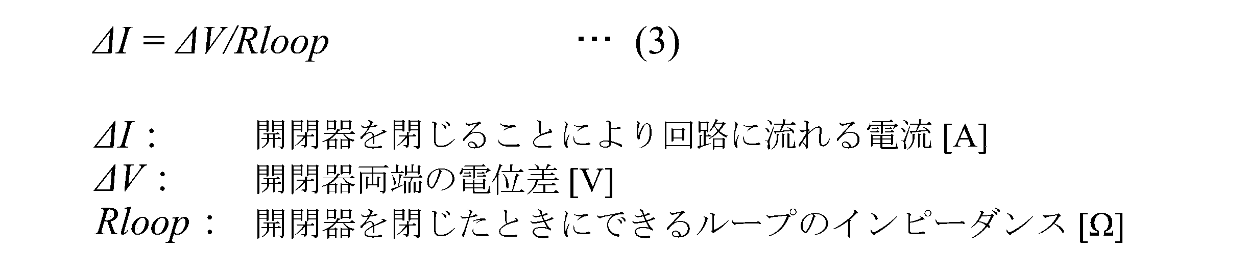
- the current flowing through the switch 91 by closing the switch 91 can be calculated by the following equation (3) using the Thevenin's law.
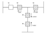
- the power transmission loss of the newly constructed radial distribution system is calculated by opening the switch that minimizes the passing current in the loop. That is, according to FIG. 14, the switch having the minimum passing current is the switch 91, and therefore the system configuration of the distribution system is the same in the operation of setting the switch 91 to the “open” state, and the transmission loss is It does not change.
- the present invention has been proposed to solve the above-described problems, and its purpose is to determine a system configuration with a practical calculation time and smaller transmission loss than the branch exchange method. It is an object of the present invention to provide an apparatus, a method and a program for determining a minimum power transmission loss system configuration.
- the present invention provides a minimum transmission loss system configuration determination device that determines a minimum transmission loss system configuration that minimizes a transmission loss among system configurations in which the switching state of the switch is changed. Therefore, it has the following technical features. That is, the minimum power transmission loss system configuration determining apparatus of the present invention first includes “closed” switch selecting means, “open” switch selecting means, power transmission loss calculating means, reduction determining means, updating means, and determining means.
- the “closed” switch selection means selects two or more open switches from a plurality of switches to be closed so as to create one mesh system in the system configuration. It is means to do.
- the “open” switch selecting means should open the same number of closed switches as the number of switches selected by the “closed” switch selecting means so as to obtain a radial system configuration. It is a means to select.
- the transmission loss calculating means changes the open switch selected by the “closed” switch selecting means to the closed state, and the open / closed switch selected by the “open” switch selecting means. It is means for calculating the transmission loss of each system configuration obtained as a result of changing the device to the open state.
- the reduction determination unit is a unit that determines whether the transmission loss of the specific system configuration newly calculated by the transmission loss calculation unit is lower than the transmission loss of another system configuration calculated earlier.
- the updating unit is a unit that updates the specific system configuration as a minimum transmission loss system candidate when the reduction determination unit determines that the transmission loss of the specific system configuration is reduced.
- the determining means is means for determining the minimum transmission loss system configuration from the minimum transmission loss system candidates. In this determination means, the reduction determination means reduces any transmission loss of each system configuration calculated by the transmission loss calculation means from the transmission loss of the minimum transmission loss system candidate that is the latest update result. If it is determined that it is not, the minimum transmission loss system candidate is determined as the minimum transmission loss system configuration.
- the “open” switch selecting means sequentially selects a switch in a closed state with a minimum passing current among the switches in the mesh system. It is.
- the “closed” switch selection means can select not only a plurality of open switches to be closed, but also a single switch in an open state. Further, a configuration in which the number of switches to be selected is changed by changing the number of switches to be selected by the “closed” switch selection unit, so that the number of switches to be selected is variable is also an aspect of the present invention. It is.
- the system includes an initial system generation unit that generates a plurality of initial systems by randomly changing the open / close state of the switch, and the “closed” switch selection unit includes each initial system generated by the initial system generation unit.
- the “closed” switch selection unit includes each initial system generated by the initial system generation unit.
- a plurality of "open” state switches are changed to the "closed” state at the same time, and the same number of switches are set to the "open” state, whereby the branch exchange method described above Compared to the above, since it is possible to search in a wide range, it is possible to provide an apparatus, method and program for determining a minimum transmission loss system configuration capable of determining a system configuration with a smaller transmission loss.
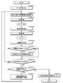
- the block block diagram of the determination apparatus of the minimum power transmission loss system structure which concerns on the 1st Embodiment of this invention The figure which shows the processing flow of the determination apparatus of the minimum power transmission loss system structure which concerns on the 1st Embodiment of this invention.
- strain structure which concerns on the 3rd Embodiment of this invention strain structure which concerns on the 3rd Embodiment of this invention.
- FIG. 1 is a block diagram illustrating the configuration of the minimum power loss system configuration determining apparatus according to the first embodiment.
- This minimum power transmission loss system configuration determining apparatus includes a calculation means 1, an input means 2, a storage means 3, a display means 4, and an I / F means 5 as shown in FIG.
- the I / F unit 5 is connected to the power distribution system 7 via the power distribution system monitoring control device 6.
- the computing means 1 is specifically realized by a main memory of a computer, a program stored in the computer, a CPU controlled by the program, etc., and has processing means 10 to 17 as will be described later.
- the input means 2 is an input device such as a mouse or a keyboard for inputting a signal corresponding to a user operation to the computer.
- the storage means 3 stores in advance various system information data of the power distribution system necessary for the processing in the computing means 1 and also stores the calculation results by the computing means 1. Realized.
- the system information data of a power distribution system is information, such as connection information (connection structure of a power distribution system) of a distribution line, an impedance, the switching state of a switch, a load, etc., for example.
- the display means 4 is a display device such as a display for displaying to the user the data input through the input means 2, the data stored in the storage means 3, and the calculation result processed by the calculation means 1.
- the I / F unit 5 is a communication interface that transmits and receives system information data and control data of the distribution system 7 via the distribution system monitoring and control device 6, and the received system information data is stored in the storage unit 3.
- the distribution system monitoring and control device 6 is a device that performs monitoring and control of the distribution system 7, and holds various data related to the planning, operation, and control of the distribution system 7.
- the computing means 1 includes a data reading means 10, a power transmission loss calculating means 11, a “closed” switch selecting means 12, a power flow calculating means 13, an “open” switch selecting means 14, a power transmission loss reduction determining means 15, an initial stage.
- System comparison means 16 and loss minimization configuration update means 17 are provided.
- the data reading means 10 is means for reading the system information data from the storage means 3, that is, the connection configuration of the distribution system, the open / close state of the switch provided in the system, and data on the load and impedance.
- system configuration to be determined, that is, “system configuration of the distribution system” means the configuration of the distribution system including the switching state of the switch, and “connection configuration of the distribution system”. Means an installation connection configuration of the distribution system that does not include the open / close state of the switch.
- the power transmission loss calculation means 11 calculates the power transmission loss in the system configuration changed by opening and closing the switch provided in the power distribution system 7.
- the “closed” switch selection means 12 selects n (n ⁇ 2) switches that are changed from the plurality of switches in the “open” state to the “closed” state among the switches constituting the distribution system 7. select.
- the power flow calculation means 13 is a means for calculating the power flow of the mesh system created by changing the n switches selected by the “closed” switch selection means 12 to the “closed” state.
- the “open” switch selecting means 14 is a mesh-like system created by changing the n switches selected by the “closed” switch selecting means 12 to the “closed” state. Among the “closed” state switches to be configured, n switches to be changed to the “open” state are selected. As an example, the “open” switch selection means 14 is a switch that should open the switch with the smallest value of current passing through the power flow of the mesh system calculated by the power flow calculation means 13. Are selected sequentially.
- the transmission loss reduction determining means 15 is a means for determining whether the transmission loss is reduced from the previous system configuration with respect to the new system configuration in which the switching state of the switch is changed. For example, it is determined whether the current power transmission loss calculated by the power transmission loss calculating means 11 is reduced as compared with the solution candidates that are sequentially updated.
- the transmission loss reduction determining unit 15 stores the current transmission loss in the storage unit 3 as a new solution candidate.
- the initial system comparison unit 16 is a unit that determines whether the transmission loss of the solution candidate is lower than the transmission loss of the initial system.
- the data reading means 10 sends system information data such as data relating to the connection configuration of the distribution system from the storage means 3, the switching state of the switches provided in the system, and the load and impedance. And data to be used in the subsequent processing are prepared.
- the system configuration used in the initial stage is the initial system configuration, and this is set as a solution candidate.
- the distribution system used as the object of minimization of power transmission loss has a radial configuration
- the initial system configuration has a radial configuration.
- the transmission loss calculation means 11 calculates the transmission loss of the solution candidate that is the initial system, and stores it in the storage means 3 as the initial transmission loss.
- the initial system configuration and the initial transmission loss stored in the storage unit 3 are adopted as the system configuration in the current distribution system, and serve as a reference for performing a system configuration update process described later.
- the “closed” switch selection means 12 is set to the “closed” state in the current system configuration, and has not yet been selected (unselected) n (n ⁇ 2) “open” state. Select a combination of switches.
- the set of n switches selected by the “closed” switch selection means 12 is selected so that one mesh system is created by closing the switch.
- the “closed” switch selecting unit 12 includes a limiting unit that limits the number of n switches to be selected. By this limiting unit, for example, the potential difference between both ends of the switch is large. The number of sets of switches can be limited in the order that includes the switches.
- the “closed” switch selecting means 12 selects n “open” switches
- the “open” switch is changed to the “closed” state on the model.
- this “closed” switch is selected.
- the power flow of the mesh system created when the state is changed is calculated by the power flow calculation means 13.
- the “open” switch selection means 14 selects one switch to be set to the “open” state among the “closed” state switches of the created mesh system. Specifically, in the power flow of the mesh system calculated by the power flow calculation means 13 in STEP 203, the switch in the “closed” state in which the current value passing through is minimized is selected as the switch to be set in the “open” state. To do. In particular, a switch in the “closed” state that minimizes the passing current is selected as a switch that should be in the “open” state based on the capacity constraint of the transmission line.
- the “open” switch selection means 14 selects the switch in the “closed” state in which the passing current value is minimum, and the selected switch The process of changing the device to the “open” state and calculating the power flow of the newly created mesh system by the flow calculation means 13 is repeated n times.
- the “open” switch selecting means 14 selects n “closed” state switches one by one, and The calculation means 13 changes the selected switch to the “open” state, and calculates the power flow n times for the remaining mesh system.
- the transmission loss calculation means 11 calculates the transmission loss of the radial system reconfigured by the processing of STEPs 204 and 205 repeated n times.
- the transmission loss reduction determination means 15 determines whether or not the current transmission loss of the radial system calculated by the transmission loss calculation means 11 is lower than the transmission loss of the solution candidate.
- the transmission system loss reduction determination means 15 causes the current system configuration and transmission loss to be a new solution candidate and The transmission loss is stored in the storage means 3.
- the transmission loss of the current system configuration is not lower than the transmission loss of the solution candidate (NO in STEP 207)
- the current system configuration is not stored as a solution candidate, and the process proceeds to STEP 209.
- the “closed” switch selecting means 12 has n “s” in different arrangements from the arrangement of the “open” state switches configured by the processing of STEPs 204 and 205 repeated n times. It is determined whether there is a set of switches in the “open” state. That is, it is determined whether there are n other “open” switch groups that have not yet been selected.
- n “open” switch sets If there are other n “open” switch sets (YES in STEP 209), the process returns to STEP 202, and a new n “open” switch set is “closed” open / close. It is selected by the device selection means 12, and the subsequent processing is repeated.
- the initial system comparison means 16 causes the transmission loss of the solution candidate in STEP 208 to be greater than the transmission loss of the initial system. It is determined whether it is reduced (STEP 210).
- the solution candidate and the transmission loss are stored in the storage unit 3 by the loss minimizing configuration updating unit 17 as the initial system configuration and the initial transmission loss.
- the initial system configuration and the initial transmission loss are updated (STEP 211).
- the processing from STEP 202 onward is repeated based on the updated initial system configuration and the initial transmission loss.
- the configuration updating unit 17 determines the current initial system configuration and initial transmission loss as the minimum transmission loss system configuration and minimum transmission loss, and displays the determined minimum transmission loss system configuration and minimum transmission loss on the display unit 4 and the I / F.
- the data is output through the means 5 (STEP 212), and the process is terminated.
- the loss minimization configuration updating unit 17 functions as a determining unit in the present invention.
- the data reading means 10 reads the power distribution system configuration (initial system configuration) as shown in FIG. 9A and the system information data as shown in FIG. 9B from the storage means 3 as initialization processing. Then, the transmission loss calculation means 11 calculates the transmission loss of the solution candidate which is the initial system configuration of FIG. 9, and obtains 57.567 [W] as shown in FIG. This power transmission loss is stored in the storage means 3 as the initial power transmission loss.
- the “closed” switch selection means 12 selects a combination of two “open” state switches that should be in the “closed” state in the system configuration of FIG. Two “open” switches are changed to the “closed” state.
- the power flow calculation means 13 calculates the power flow of the mesh system created when the state is changed to the “closed” state.
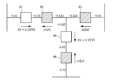
- the “open” switch selecting means 14 selects the switch 92 that minimizes the passing current, and the system configuration as shown in FIG. Is obtained.
- the power flow calculation means 13 calculates the power flow of the new mesh system in FIG. 4 created when the state is changed to the “open” state.
- the power transmission loss calculation means 11 calculates the power transmission loss of the newly configured system configuration, and as shown in FIG. 12, the power transmission loss 56.267 corresponding to the system configuration of FIG. [A] is obtained.
- the power transmission loss reduction determining means 15 determines whether or not the power transmission loss corresponding to the system configuration of FIG. 11 (f) calculated by the power transmission loss calculating means 11 is lower than the solution loss of the solution candidate. .
- the power transmission loss reduction determination unit 15 includes the power transmission loss 56.267 [W] of the system configuration and the initial power transmission loss 57.567 [W] calculated by the power transmission loss calculation unit 11 in the initialization process of STEP 201. By comparing (see FIG. 10), it is determined that the current transmission loss is lower than the solution loss of the solution candidate. As shown in FIG. 12, there is no system configuration capable of reducing the transmission loss from this transmission loss 56.267 [W], so even when another set of “open” state switches is selected, There is no system configuration lower than the transmission loss of the system configuration in FIG.
- the transmission loss reduction determination means 15 newly sets this system configuration and transmission loss 56.267 [W]. Are stored in the storage means 3 as possible solution candidates and their transmission losses.
- the “closed” switch selection means 12 determines whether there are two “open” switch groups having different arrangements with respect to the system configuration of FIG. The If there are other two “open” switch groups (YES in STEP 209), the process returns to STEP 202 and two new “open” switch groups are “closed”. “Selected by the switch selection means 12, and the subsequent processing is repeated.
- the initial system comparison means 16 causes the transmission loss of the solution candidate in STEP 208 to be greater than the transmission loss of the initial system. It is determined whether it is reduced (STEP 210).
- the loss minimizing configuration updating unit 17 stores the solution candidate and the power transmission loss in the storage unit 3 as the initial system configuration and the initial power transmission loss.
- the initial system configuration and the initial transmission loss are updated (STEP 211).
- the processing from STEP 202 onward is repeated based on the updated initial system configuration and the initial transmission loss.
- the configuration updating unit 17 determines the current initial system configuration and initial transmission loss as the minimum transmission loss system configuration and minimum transmission loss, and displays the determined minimum transmission loss system configuration and minimum transmission loss on the display unit 4 and the I / F.
- the data is output through the means 5 (STEP 212), and the process is terminated. That is, the system configuration in FIG. 11F is output as the minimum power transmission system configuration that minimizes the power transmission loss.
- the “open” switch selecting means 14 selects one switch in the “closed” state to be set in the “open” state one by one, but the present invention is limited to this mode. Not what you want. That is, the present invention also includes an embodiment in which n switches that are in the “closed” state at a time are selected and changed to the “open” state.
- FIG. 5 is a block diagram showing a configuration of a determination apparatus for a minimum transmission loss system configuration according to the second embodiment for minimizing transmission loss.
- the same components as those in FIG. 5 are identical to those in FIG.
- a switch number changing means 18 is provided.
- the switch number changing means 18 changes the number of switches to be selected at one time by the “closed” switch selecting means 12.
- the switch number changing means 18 determines whether the number of selected switches is equal to n, which is a predetermined number of preset switches, and the number of selected switches is less than n. In this case, the number of switches to be selected at a time is increased by one up to n.
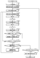
- FIG. 6 is a diagram illustrating a system configuration determination flow that minimizes power transmission loss according to the second embodiment.
- the data reading means 10 relates to the connection configuration of the distribution system from the storage means 3, the switching state of the switch provided in the system, and the load and impedance.
- System information data such as data is read, and data to be used in the subsequent processing is prepared.
- the system configuration used in the initial stage is the initial system configuration, and this is set as a solution candidate.
- the transmission loss calculation means 11 calculates the transmission loss of the solution candidate that is the initial system, and stores it in the storage means 3 as the initial transmission loss.
- the initial power transmission system and the initial power transmission loss stored in the storage unit 3 are adopted as a system configuration in the current distribution system, and serve as a reference for performing a system configuration update process to be described later.
- step 602 when selecting n (n ⁇ 1) “open” state switches that have not yet been selected, the “closed” switch selection unit 12 should be in the “closed” state.
- the “closed” switch selecting unit 12 includes a limiting unit that limits the number of n switches to be selected. By this limiting unit, for example, the potential difference between both ends of the switch is large. The number of sets can be limited in the order including switches.
- the power flow calculation means 13 calculates the power flow of the mesh system created when the state is changed to the “closed” state.
- one of the switches in the “closed” state of the created mesh system is selected by the “open” switch selection means 14 to be in the “open” state.
- the switch in the “closed” state in which the passing current value is minimum is selected as the switch to be set in the “open” state.
- a switch in the “closed” state that minimizes the passing current is selected as a switch that should be in the “open” state based on the capacity constraint of the transmission line.
- the “open” switch selecting means 14 selects one “closed” switch
- the “closed” switch is changed to the “open” state on the model.
- this “open” switch is selected.
- the power flow of the new mesh system created when the state is changed is calculated by the power flow calculation means 13.
- the power transmission loss calculation means 11 calculates the power transmission loss of the reconfigured radial system.
- the power transmission loss reduction determination means 15 calculates the current power transmission loss of the radial system calculated by the power transmission loss calculation means 11. However, it is determined whether or not it is lower than the transmission loss of the solution candidate.
- STEP 609 there is one “open” switch group in which the “closed” switch selection means 12 is arranged differently from the arrangement of the “open” switch in the configured system configuration. Determine whether. That is, it is determined whether there is one other “open” switch group that has not yet been selected.
- the “closed” switch selecting means 12 opens and closes n “open” states of the system configuration configured by repeating the processes of STEPs 604 and 605 n times. It is determined whether there is a set of n “open” switches in a different arrangement from the arrangement of the appliances.
- the process returns to STEP 602, and one new “open” switch set is “closed” open / close. It is selected by the device selection means 12, and the subsequent processing is repeated.
- the initial system comparison means 16 causes the transmission loss of the solution candidate in STEP 608 to be greater than the transmission loss of the initial system. It is determined whether it is reduced (STEP 610).
- the solution candidate and the transmission loss are stored in the storage unit 3 by the loss minimizing configuration updating unit 17 as the initial system configuration and the initial transmission loss.
- the initial system configuration and its initial transmission loss are updated (STEP 611).
- the processing from STEP 602 is repeated on the basis of the updated initial system configuration and the initial transmission loss.
- the switch number changing means 18 determines whether or not the number of switches selected by the “closed” switch selection means 12 is equal to a preset number of n (a preset number of preset switches).
- the “open” switch selection unit 14 minimizes the passing current value based on the calculated power flow.
- the process is changed to the “open” state, and the power flow calculating means 13 calculates the power flow of the newly created mesh system n times.
- the switch number changing unit 18 determines that the number of switches selected by the “closed” switch selecting unit 12 is equal to the preset number n (YES in STEP612)
- the updated configuration update means 17 determines the current initial system configuration and initial transmission loss as the minimum transmission loss system configuration and minimum transmission loss, and displays the determined minimum transmission loss system configuration and minimum transmission loss on the display unit 4 and the I / I
- the data is output through the F means 5 (STEP 613), and the process is terminated.
- the number of switches that are changed from the “open” state to the “closed” state at a time can be increased sequentially from 1, so that the search range is expanded.
- the minimum transmission loss can be calculated at high speed in the initial stage when the number of switches to be changed is small, and the number of switches to be changed has increased. In the stage, it is possible to gradually improve the degree of minimization of transmission loss.
- the switch number changing means 18 in the above embodiment determines whether or not the number of switches selected by the “closed” switch selection means 12 is equal to the preset n, and this preset n The number of switches is increased when the number is less than one, but the present invention is not limited to this.
- FIG. 7 is a block diagram showing a determination apparatus for a minimum transmission loss system configuration according to the third embodiment for minimizing transmission loss.
- an initial system generation unit 19 an initial system selection unit 20, and a minimized configuration selection unit 21 are provided.
- the initial system generation means 19 is a means for generating a plurality of initial system configurations having different system configurations from a certain initial system.
- the initial system selection means 20 is a means for selecting an initial system that has not yet been selected from a plurality of initial systems, and the minimized configuration selection means 21 is a solution candidate for minimizing transmission loss for each initial system configuration. It is a means for selecting the one with the smallest transmission loss from all the obtained system configurations.
- FIG. 8 is a figure which shows the determination flow of the system
- the description of the same processing as the flowchart of FIG. 2 is omitted.
- the data reading unit 10 is configured to transmit data such as the connection configuration of the power distribution system from the storage unit 3, the open / close state of the switch provided in the system, and data regarding the load and impedance.
- System information data is read and data to be used in the subsequent processing is prepared.
- the system configuration used in the initial stage is the initial system configuration, and this is set as a solution candidate.
- the transmission loss calculation means 11 calculates the transmission loss of the solution candidate that is the initial system, and stores it in the storage means 3 as the initial transmission loss.
- the initial power transmission system and the initial power transmission loss stored in the storage unit 3 are adopted as a system configuration in the current distribution system, and serve as a reference for performing a system configuration update process to be described later.
- the initial system generation unit 19 creates a plurality of different system configurations for the read initial system, and the transmission loss calculation unit 11 calculates the initial transmission loss for each system configuration.
- the plurality of initial system configurations created by the initial system generation means 19 are, for example, closing a randomly selected “open” state switch with respect to the initial system, and in the configured mesh system, It is created by opening a randomly selected switch.
- the initial system selection unit 20 selects a new system configuration that has not yet been selected among the plurality of initial system configurations created by the initial system generation unit 19. Thereafter, by executing the same processing as the processing of STEPs 202 to 211 in FIG. 2 in the first embodiment, the minimum transmission loss and the minimum transmission loss system configuration calculated based on the selected initial system configuration are obtained. Can be derived (STEP 804-813).
- the initial system selection means 20 determines whether there is another initial system configuration that has not yet been subjected to power transmission loss minimization processing. If there is present (YES in STEP 814), the process proceeds to STEP 803. A new initial system configuration is selected.
- the minimized configuration selection unit 21 minimizes the transmission loss for each initial system configuration. From all system configurations obtained as candidate solutions, select the system configuration that minimizes the transmission loss, determine the selected system configuration and its transmission loss as the minimum transmission loss system configuration and minimum transmission loss, and display them. The data is output through the means 4 and the I / F means 5, and the process is terminated.
- the present invention selects the initial system configuration means 19 for generating a plurality of initial systems having different system configurations and an initial system configuration that has not yet been selected from the plurality of initial system configurations according to the third embodiment.
- the initial system selection means 20 and the minimization configuration selection means 21 for selecting the system configuration with the minimum power transmission loss among the system configurations with the minimum power transmission loss calculated based on all the initial system configurations.
- Embodiments applied to the forms are also included.
- the data reading unit 10 receives data such as the configuration of the power distribution system from the storage unit 3, the open / close state of the switch provided in the system, and data on the load and impedance.
- the system information data is read, and as an initialization process, the initial system generation unit 19 creates a plurality of different system configurations, and the transmission loss calculation unit 11 calculates the initial transmission loss for each system configuration.
- the initial system selection unit 20 selects a new system configuration that has not yet been selected from among the plurality of initial system configurations created by the initial system generation unit 19, and STEPs 602 to 612 are performed based on the initial system configuration.
- the process is executed.
- the switch number changing unit 18 determines that the number of switches selected by the “closed” switch selecting unit 12 is equal to a preset n (predetermined threshold) (YES in STEP612) )
- the initial system selection means 20 determines whether there is another initial system configuration that has not been subjected to the power transmission loss minimization process.
- the initial system selection unit 20 When it is determined by the initial system selection unit 20 that there is another initial system configuration that has not been subjected to the power transmission loss minimization process, the initial system selection unit 20 includes a plurality of items created by the initial system generation unit 19. By selecting a new system configuration that has not been selected from among the initial system configurations, the processing from STEPs 602 to 612 is repeated.
- the minimized configuration selection unit 21 is obtained as a solution candidate for minimizing the transmission loss for each initial system configuration.
- the system configuration that minimizes the transmission loss is selected from all the system configurations, the selected system configuration and the transmission loss are determined as the minimum transmission loss system configuration and the minimum transmission loss, and the display means 4 and the I / I The data is output through the F means 5 and the process is terminated.
Landscapes
- Engineering & Computer Science (AREA)
- Power Engineering (AREA)
- Supply And Distribution Of Alternating Current (AREA)
- Operating, Guiding And Securing Of Roll- Type Closing Members (AREA)
- Remote Monitoring And Control Of Power-Distribution Networks (AREA)
Abstract
Description


ΔV = -0.42-(-0.05-0.125-0.225-0.35) = 0.33
となる。そして、得られたこの電位差と式(3)から、開閉器91を閉じることで生じる電流変化は、
ΔI = 0.33/(0.028+0.01+0.01+0.01+0.01+0.01) = 4.853[A]
となる。従って、開閉器91を閉じた後の開閉器91~93、95の通過電流は図14のようになる。
[構成]
次に、本発明の第1の実施形態に係る配電系統の送電損失が最小となる最小送電損失系統構成の決定装置の構成について、図1~4を参照して以下に説明する。なお、図1は、第1の実施形態に係る最小送電損失系統構成の決定装置の構成を示すブロック図である。
次に、図1の構成を有する最小送電損失系統構成の決定装置において、送電損失が最小となる系統構成の決定手順を、図2のフローチャートを参照して以下に説明する。
次に、放射状の配電系統の一例を示す図9、11を再び参照し、図2~4に基づいて、第1の実施形態の具体的な実施例について以下に説明する。なお、図2の通り、図9(a)には、2つの「開」状態の開閉器しか存在しないため、n=2とする。
以上のような第1の実施形態によれば、複数の「開」状態の開閉器を一度に「閉」状態に変更し同数の開閉器を「開」状態とすることで探索範囲を広くすることが可能となり、送電損失をより小さくする系統構成を決定可能で、かつ系統構成の決定に要する時間を短縮可能な最小送電損失系統構成の決定装置、方法及びプログラムを提供することができる。
[構成]
次に、本発明の第2の実施形態に係る配電系統の送電損失が最小となる最小送電損失系統構成の決定装置の構成について、図5を参照して以下に説明する。なお、図5は、送電損失の最小化を図るための第2の実施形態に係る最小送電損失系統構成の決定装置の構成を示すブロック図である。ここで、図5において、図1と同じ構成には同じ符号を用い、説明は省略する。
次に、図5の構成を有する最小送電損失系統構成の決定装置において、送電損失が最小となる系統構成の決定手順を、図6のフローチャートを参照して以下に説明する。なお、図6は、第2の実施形態に係り、送電損失が最小となる系統構成の決定フローを示す図である。
以上のような第2の実施形態によれば、一度に「開」状態から「閉」状態に変更する開閉器の数を1から順に増加させることができるので探索範囲が拡大する。その結果、計算時間が実質的に大きくなる問題に対して、変更すべき開閉器の数が少ない初期段階においては最小となる送電損失を高速に算出でき、変更すべき開閉器の数が増加した段階においては徐々に送電損失の最小化の程度を向上させることが可能となる。
[構成]
次に、本発明の第3の実施形態に係る最小送電損失系統構成の決定装置の構成について、図7を参照して以下に説明する。なお、図7は、送電損失の最小化を図るための第3の実施形態に係る最小送電損失系統構成の決定装置を示すブロック図である。ここで、図7において、図1と同じ構成には同じ符号を用い、説明は省略する。
次に、図7の構成を有する最小送電損失系統構成の決定装置において、送電損失が最小となる系統構成の決定手順を、図8のフローチャートを参照して以下に説明する。なお、図8は、第3の実施形態に係り、送電損失が最小となる系統構成の決定フローを示す図である。ここで、図2のフローチャートと同じ処理については説明を省略する。
以上のような本実施形態によれば、予め複数の初期系統構成を作成することができるので、各初期系統構成に対して最小となる送電損失を算出することが可能となり、送電損失の算出処理が局所解に陥ることを回避することができる。そのため、広範囲を探索の対象とすることができ、より送電損失の小さい系統構成を決定することが可能となる。
なお、本発明は、この第3の実施形態に係る、系統構成の異なる複数の初期系統を生成する初期系統生成手段19と、複数の初期系統構成からまだ選択されていない初期系統構成を選択する初期系統選択手段20と、すべての初期系統構成に基づいて算出された送電損失が最小となる系統構成のうち送電損失が最小のものを選択する最小化構成選択手段21と、を第2の実施形態に対して適用した実施形態も包含する。
2…入力手段
3…記憶手段
4…表示手段
5…I/F手段
6…配電系統監視制御装置
7…配電系統
9a~9g…区間番号
10…データ読出手段
11…送電損失計算手段
12…「閉」開閉器選択手段
13…潮流計算手段
14…「開」開閉器選択手段
15…送電損失低減判定手段
16…初期系統対比手段
17…損失最小化構成更新手段
18…開閉器数変更手段
19…初期系統生成手段
20…初期系統選択手段
21…最小化構成選択手段
91~95…開閉器
Claims (13)
- 開閉器の開閉状態が変更された系統構成のうち、送電損失が最小となる最小送電損失系統構成を決定する最小送電損失系統構成の決定装置であって、
前記系統構成内で1つのメッシュ状系統を作成するように、複数の開閉器から2個以上の開状態にある開閉器を閉状態にすべく選択する「閉」開閉器選択手段と、
前記「閉」開閉器選択手段により選択された開閉器数と同数の閉状態にある開閉器を、放射状の系統構成が得られるように、開状態にすべく選択する「開」開閉器選択手段と、
前記「閉」開閉器選択手段により選択された開状態にある開閉器を閉状態に変更し、かつ、前記「開」開閉器選択手段により選択された閉状態にある開閉器を開状態に変更した結果として得られる各系統構成の送電損失を計算する送電損失計算手段と、
前記送電損失計算手段により新たに計算された特定の系統構成の送電損失が、先に計算された別の系統構成の送電損失よりも低減しているかを判定する低減判定手段と、
前記低減判定手段により前記特定の系統構成の送電損失が低減していると判定された場合に、当該特定の系統構成を最小送電損失系統候補として更新する更新手段と、
最小送電損失系統候補から最小送電損失系統構成を決定する決定手段と、
を備え、
前記決定手段は、前記低減判定手段が、前記送電損失計算手段により計算された各系統構成の送電損失のいずれもが、最新の更新結果である前記最小送電損失系統候補の送電損失よりも低減していないと判定した場合に、当該最小送電損失系統候補を最小送電損失系統構成として決定することを特徴とする最小送電損失系統構成の決定装置。 - 前記「開」開閉器選択手段は、前記メッシュ状系統内の開閉器のうち、通過電流が最小の閉状態にある開閉器を逐次選択することを特徴とする請求項1に記載の最小送電損失系統構成の決定装置。
- 前記「開」開閉器選択手段は、系統の送電線の容量制約のもとで、通過電流が最小の閉状態にある開閉器を逐次選択することを特徴とする請求項2に記載の最小送電損失系統構成の決定装置。
- 前記「閉」開閉器選択手段により選択される開状態にある開閉器の選択個数を制限する制限手段を備えたことを特徴とする請求項1に記載の最小送電損失系統構成の決定装置。
- 開閉器の開閉状態が変更された系統構成のうち、送電損失が最小となる最小送電損失系統構成を決定する最小送電損失系統構成の決定装置であって、
前記系統構成内で1つのメッシュ状系統を作成するように、複数の開閉器から開状態にある開閉器を閉状態にすべく選択する「閉」開閉器選択手段と、
前記「閉」開閉器選択手段により選択される開閉器数を変更する開閉器数変更手段と、
前記「閉」開閉器選択手段により選択された開閉器数と同数の閉状態にある開閉器を、放射状の系統構成が得られるように、開状態にすべく選択する「開」開閉器選択手段と、
前記「閉」開閉器選択手段により選択された開状態にある開閉器を閉状態に変更し、かつ、前記「開」開閉器選択手段により選択された閉状態にある開閉器を開状態に変更した結果として得られる各系統構成の送電損失を計算する送電損失計算手段と、
前記送電損失計算手段により新たに計算された特定の系統構成の送電損失が、先に計算された別の系統構成の送電損失よりも低減しているかを判定する低減判定手段と、
前記低減判定手段により前記特定の系統構成の送電損失が低減していると判定された場合に、当該特定の系統構成を最小送電損失系統候補として更新する更新手段と、
最小送電損失系統候補から最小送電損失系統構成を決定する決定手段と、
を備え、
前記決定手段は、前記低減判定手段が、前記送電損失計算手段により計算された各系統構成の送電損失のいずれもが、最新の更新結果である前記最小送電損失系統候補の送電損失よりも低減していないと判定した場合に、当該最小送電損失系統候補を最小送電損失系統構成として決定することを特徴とする最小送電損失系統構成の決定装置。 - 前記開閉器数変更手段は、前記低減判定手段により前記特定の系統構成の送電損失が先に計算された別の系統構成の送電損失よりも低減していないと判定された場合に、前記「閉」開閉器選択手段が選択する開閉器数を増加させることを特徴とする請求項5に記載の最小送電損失系統構成の決定装置。
- ランダムに開閉器の開閉状態を変更することにより複数の初期系統を生成する初期系統生成手段を備え、
前記「閉」開閉器選択手段は、前記初期系統生成手段により生成された各初期系統内で1つのメッシュ状系統を作成するように、開状態にある開閉器を選択することを特徴とする請求項1又は5に記載の最小送電損失系統構成の決定装置。 - 開閉器の開閉状態が変更された系統構成のうち、送電損失が最小となる最小送電損失系統構成を決定する最小送電損失系統構成の決定方法であって、
前記系統構成内で1つのメッシュ状系統を作成するように、複数の開閉器から2個以上の開状態にある開閉器を閉状態にすべく選択する「閉」開閉器選択ステップと、
前記「閉」開閉器選択ステップにより選択された開閉器数と同数の閉状態にある開閉器を、放射状の系統構成が得られるように、開状態にすべく選択する「開」開閉器選択ステップと、
前記「閉」開閉器選択ステップにより選択された開状態にある開閉器を閉状態に変更し、かつ、前記「開」開閉器選択ステップにより選択された閉状態にある開閉器を開状態に変更した結果として得られる各系統構成の送電損失を計算する送電損失計算ステップと、
前記送電損失計算ステップにより新たに計算された特定の系統構成の送電損失が、先に計算された別の系統構成の送電損失よりも低減しているかを判定する低減判定ステップと、
前記低減判定ステップにより前記特定の系統構成の送電損失が低減していると判定された場合に、当該特定の系統構成を最小送電損失系統候補として更新する更新ステップと、
最小送電損失系統候補から最小送電損失系統構成を決定する決定ステップと、
を含み、
前記決定ステップは、前記低減判定ステップで、前記送電損失計算ステップにより計算された各系統構成の送電損失のいずれもが、最新の更新結果である前記最小送電損失系統候補の送電損失よりも低減していないと判定した場合に、当該最小送電損失系統候補を最小送電損失系統構成として決定することを特徴とする最小送電損失系統構成の決定方法。 - 前記「開」開閉器選択ステップは、前記メッシュ状系統内の開閉器のうち、通過電流が最小の閉状態にある開閉器を逐次選択することを特徴とする請求項8に記載の最小送電損失系統構成の決定方法。
- 開閉器の開閉状態が変更された系統構成のうち、送電損失が最小となる最小送電損失系統構成を決定する最小送電損失系統構成の決定方法であって、
前記系統構成内で1つのメッシュ状系統を作成するように、複数の開閉器から開状態にある開閉器を閉状態にすべく選択する「閉」開閉器選択ステップと、
前記「閉」開閉器選択ステップにより選択される開閉器数を変更する開閉器数変更ステップと、
前記「閉」開閉器選択ステップにより選択された開閉器数と同数の閉状態にある開閉器を、放射状の系統構成が得られるように、開状態にすべく選択する「開」開閉器選択ステップと、
前記「閉」開閉器選択ステップにより選択された開状態にある開閉器を閉状態に変更し、かつ、前記「開」開閉器選択ステップにより選択された閉状態にある開閉器を開状態に変更した結果として得られる各系統構成の送電損失を計算する送電損失計算ステップと、
前記送電損失計算ステップにより新たに計算された特定の系統構成の送電損失が、先に計算された別の系統構成の送電損失よりも低減しているかを判定する低減判定ステップと、
前記低減判定ステップにより前記特定の系統構成の送電損失が低減していると判定された場合に、当該特定の系統構成を最小送電損失系統候補として更新する更新ステップと、
最小送電損失系統候補から最小送電損失系統構成を決定する決定ステップと、
を含み、
前記決定ステップは、前記低減判定ステップで、前記送電損失計算ステップにより計算された各系統構成の送電損失のいずれもが、最新の更新結果である前記最小送電損失系統候補の送電損失よりも低減していないと判定した場合に、当該最小送電損失系統候補を最小送電損失系統構成として決定することを特徴とする最小送電損失系統構成の決定方法。 - 前記開閉器数変更ステップは、前記低減判定ステップにより前記特定の系統構成の送電損失が先に計算された別の系統構成の送電損失よりも低減していないと判定された場合に、前記「閉」開閉器選択ステップで選択する開閉器数を増加させることを特徴とする請求項10に記載の最小送電損失系統構成の決定方法。
- ランダムに開閉器の開閉状態を変更することにより複数の初期系統を生成する初期系統生成ステップを含み、
前記「閉」開閉器選択ステップは、前記初期系統生成ステップにより生成された各初期系統内で1つのメッシュ状系統を作成するように、開状態にある開閉器を選択することを特徴とする請求項8又は10に記載の最小送電損失系統構成の決定方法。 - コンピュータに、開閉器の開閉状態が変更された系統構成のうち、送電損失が最小となる最小送電損失系統構成を決定させる最小送電損失系統構成の決定プログラムであって、
前記コンピュータに、
前記系統構成内で1つのメッシュ状系統を作成するように、複数の開閉器から2個以上の開状態にある開閉器を閉状態にすべく選択する「閉」開閉器選択処理と、
前記「閉」開閉器選択処理により選択された開閉器数と同数の閉状態にある開閉器を、放射状の系統構成が得られるように、開状態にすべく選択する「開」開閉器選択処理と、
前記「閉」開閉器選択処理により選択された開状態にある開閉器を閉状態に変更し、かつ、前記「開」開閉器選択処理により選択された閉状態にある開閉器を開状態に変更した結果として得られる各系統構成の送電損失を計算する送電損失計算処理と、
前記送電損失計算処理により新たに計算された特定の系統構成の送電損失が、先に計算された別の系統構成の送電損失よりも低減しているかを判定する低減判定処理と、
前記低減判定処理により前記特定の系統構成の送電損失が低減していると判定された場合に、当該特定の系統構成を最小送電損失系統候補として更新する更新処理と、
最小送電損失系統候補から最小送電損失系統構成を決定する決定処理と、
を実行させ、
前記決定処理は、前記低減判定処理で、前記送電損失計算処理により計算された各系統構成の送電損失のいずれもが、最新の更新結果である前記最小送電損失系統候補の送電損失よりも低減していないと判定した場合に、当該最小送電損失系統候補を最小送電損失系統構成として決定することを特徴とする最小送電損失系統構成の決定プログラム。
Priority Applications (1)
| Application Number | Priority Date | Filing Date | Title |
|---|---|---|---|
| CN2009801182235A CN102037627B (zh) | 2008-05-20 | 2009-05-20 | 最小送电损失系统构成的决定装置、方法 |
Applications Claiming Priority (2)
| Application Number | Priority Date | Filing Date | Title |
|---|---|---|---|
| JP2008132521A JP5395367B2 (ja) | 2008-05-20 | 2008-05-20 | 最小送電損失系統構成の決定装置、方法及びプログラム |
| JP2008-132521 | 2008-05-20 |
Publications (1)
| Publication Number | Publication Date |
|---|---|
| WO2009142011A1 true WO2009142011A1 (ja) | 2009-11-26 |
Family
ID=41339951
Family Applications (1)
| Application Number | Title | Priority Date | Filing Date |
|---|---|---|---|
| PCT/JP2009/002224 Ceased WO2009142011A1 (ja) | 2008-05-20 | 2009-05-20 | 最小送電損失系統構成の決定装置、方法及びプログラム |
Country Status (3)
| Country | Link |
|---|---|
| JP (1) | JP5395367B2 (ja) |
| CN (1) | CN102037627B (ja) |
| WO (1) | WO2009142011A1 (ja) |
Families Citing this family (7)
| Publication number | Priority date | Publication date | Assignee | Title |
|---|---|---|---|---|
| KR101246383B1 (ko) * | 2011-09-27 | 2013-03-21 | 한국전력공사 | 배전계통의 구간부하 특성을 고려한 배전손실 최소화 장치 및 방법 |
| KR101715778B1 (ko) * | 2015-10-29 | 2017-03-15 | (주)에스엔 | 시간차 동기 알고리즘 기반 송배전 계통 손실전력 측정 방법 |
| KR101926307B1 (ko) * | 2018-05-28 | 2019-03-07 | (주)세니온 | 배전 자동화 시스템 제어방법 |
| KR101926306B1 (ko) * | 2018-05-28 | 2018-12-06 | 이동률 | 배전 자동화 시스템 |
| KR101926309B1 (ko) * | 2018-05-28 | 2018-12-06 | 이동률 | 분산전원 관리가 가능한 배전 자동화 시스템 제어방법 |
| KR101926308B1 (ko) * | 2018-05-28 | 2018-12-06 | 이동률 | 분산전원 관리가 가능한 배전 자동화 시스템 |
| JP7303500B2 (ja) * | 2019-03-13 | 2023-07-05 | 株式会社明電舎 | 配電系統制御装置 |
Citations (6)
| Publication number | Priority date | Publication date | Assignee | Title |
|---|---|---|---|---|
| JPS63316637A (ja) * | 1987-06-19 | 1988-12-23 | Tokyo Electric Power Co Inc:The | 送電損失最小化方法 |
| JPH04210735A (ja) * | 1990-11-30 | 1992-07-31 | Toshiba Corp | 電力系統制御装置 |
| JPH05130736A (ja) * | 1991-07-11 | 1993-05-25 | Kyushu Electric Power Co Inc | 配電系統制御装置 |
| JPH05344651A (ja) * | 1992-06-11 | 1993-12-24 | Toshiba Corp | 配電系統操作装置 |
| JPH08308110A (ja) * | 1995-04-27 | 1996-11-22 | Hitachi Ltd | 配電系統制御装置 |
| JPH1056737A (ja) * | 1996-08-07 | 1998-02-24 | Toshiba Corp | 配電系統運用装置 |
Family Cites Families (1)
| Publication number | Priority date | Publication date | Assignee | Title |
|---|---|---|---|---|
| JP3364826B2 (ja) * | 1997-02-24 | 2003-01-08 | 株式会社日立製作所 | 配電系統構成の作成方法及び装置 |
-
2008
- 2008-05-20 JP JP2008132521A patent/JP5395367B2/ja not_active Expired - Fee Related
-
2009
- 2009-05-20 WO PCT/JP2009/002224 patent/WO2009142011A1/ja not_active Ceased
- 2009-05-20 CN CN2009801182235A patent/CN102037627B/zh not_active Expired - Fee Related
Patent Citations (6)
| Publication number | Priority date | Publication date | Assignee | Title |
|---|---|---|---|---|
| JPS63316637A (ja) * | 1987-06-19 | 1988-12-23 | Tokyo Electric Power Co Inc:The | 送電損失最小化方法 |
| JPH04210735A (ja) * | 1990-11-30 | 1992-07-31 | Toshiba Corp | 電力系統制御装置 |
| JPH05130736A (ja) * | 1991-07-11 | 1993-05-25 | Kyushu Electric Power Co Inc | 配電系統制御装置 |
| JPH05344651A (ja) * | 1992-06-11 | 1993-12-24 | Toshiba Corp | 配電系統操作装置 |
| JPH08308110A (ja) * | 1995-04-27 | 1996-11-22 | Hitachi Ltd | 配電系統制御装置 |
| JPH1056737A (ja) * | 1996-08-07 | 1998-02-24 | Toshiba Corp | 配電系統運用装置 |
Also Published As
| Publication number | Publication date |
|---|---|
| JP2009284614A (ja) | 2009-12-03 |
| CN102037627B (zh) | 2013-07-10 |
| CN102037627A (zh) | 2011-04-27 |
| JP5395367B2 (ja) | 2014-01-22 |
Similar Documents
| Publication | Publication Date | Title |
|---|---|---|
| EP3671374B1 (en) | Method and system for determining system settings for an industrial system | |
| da Silva et al. | Transmission expansion planning optimization by adaptive multi-operator evolutionary algorithms | |
| JP5395367B2 (ja) | 最小送電損失系統構成の決定装置、方法及びプログラム | |
| EP3029614A1 (en) | Parallel development and deployment for machine learning models | |
| JP2019159637A (ja) | 最適化装置及び最適化装置の制御方法 | |
| EP3611799A1 (en) | Array element arrangement method for l-type array antenna based on inheritance of acquired characteristics | |
| Wang et al. | A graph-based ant colony optimization approach for integrated process planning and scheduling | |
| US20200265295A1 (en) | Data processing apparatus, data processing method, and storage medium | |
| JPWO2016151620A1 (ja) | シミュレートシステム、シミュレート方法およびシミュレート用プログラム | |
| JP2023139286A (ja) | 回路情報、情報処理方法、プログラムおよび情報処理システム | |
| JP2020030738A (ja) | 学習データの解析方法及び計算機システム | |
| JP6333342B2 (ja) | 人工知能に基づく検索方法及び装置 | |
| US10936297B2 (en) | Method, device, and computer program product for updating software | |
| EP3792833A2 (en) | Reservoir computer, reservoir designing method, and reservoir designing program | |
| JP2020187453A (ja) | 最適化装置および最適化装置の制御方法 | |
| EP3852027B1 (en) | Optimization device, control method of optimization device, and control program of optimization device | |
| JP2000197270A (ja) | 配電系統における調相設備の最適設置箇所決定方法 | |
| CN116187155A (zh) | 生成最佳输入数据的计算设备和方法 | |
| JP2019016324A (ja) | 予測装置、予測方法および予測プログラム | |
| Vieira et al. | isklearn: Automated machine learning with irace | |
| Amali et al. | Fuzzy logic-based diversity-controlled self-adaptive differential evolution | |
| CN116151383B (zh) | 量子计算处理方法、装置及电子设备 | |
| JP2019160293A (ja) | 最適化装置及び最適化装置の制御方法 | |
| Shayeghi et al. | Application of PSO and GA for transmission network expansion planning | |
| CN114116151A (zh) | 一种基于先验知识的大数据框架配置参数优化方法 |
Legal Events
| Date | Code | Title | Description |
|---|---|---|---|
| WWE | Wipo information: entry into national phase |
Ref document number: 200980118223.5 Country of ref document: CN |
|
| 121 | Ep: the epo has been informed by wipo that ep was designated in this application |
Ref document number: 09750373 Country of ref document: EP Kind code of ref document: A1 |
|
| WWE | Wipo information: entry into national phase |
Ref document number: 8146/DELNP/2010 Country of ref document: IN |
|
| NENP | Non-entry into the national phase |
Ref country code: DE |
|
| 122 | Ep: pct application non-entry in european phase |
Ref document number: 09750373 Country of ref document: EP Kind code of ref document: A1 |