WO2009139466A1 - データ収集方法 - Google Patents
データ収集方法 Download PDFInfo
- Publication number
- WO2009139466A1 WO2009139466A1 PCT/JP2009/059059 JP2009059059W WO2009139466A1 WO 2009139466 A1 WO2009139466 A1 WO 2009139466A1 JP 2009059059 W JP2009059059 W JP 2009059059W WO 2009139466 A1 WO2009139466 A1 WO 2009139466A1
- Authority
- WO
- WIPO (PCT)
- Prior art keywords
- cancer
- lesion
- image
- indocyanine green
- distribution image
- Prior art date
Links
- 238000000034 method Methods 0.000 title claims abstract description 32
- 238000013480 data collection Methods 0.000 title claims abstract description 18
- 230000003902 lesion Effects 0.000 claims abstract description 150
- 206010028980 Neoplasm Diseases 0.000 claims abstract description 139
- 201000011510 cancer Diseases 0.000 claims abstract description 119
- MOFVSTNWEDAEEK-UHFFFAOYSA-M indocyanine green Chemical compound [Na+].[O-]S(=O)(=O)CCCCN1C2=CC=C3C=CC=CC3=C2C(C)(C)C1=CC=CC=CC=CC1=[N+](CCCCS([O-])(=O)=O)C2=CC=C(C=CC=C3)C3=C2C1(C)C MOFVSTNWEDAEEK-UHFFFAOYSA-M 0.000 claims abstract description 79
- 229960004657 indocyanine green Drugs 0.000 claims abstract description 76
- 210000000056 organ Anatomy 0.000 claims abstract description 45
- 230000005284 excitation Effects 0.000 claims abstract description 43
- 238000005481 NMR spectroscopy Methods 0.000 claims abstract description 11
- 230000001678 irradiating effect Effects 0.000 claims abstract description 7
- 238000003384 imaging method Methods 0.000 claims description 39
- 238000001514 detection method Methods 0.000 claims description 30
- 238000012360 testing method Methods 0.000 claims description 25
- 238000001356 surgical procedure Methods 0.000 claims description 15
- 239000003795 chemical substances by application Substances 0.000 claims description 13
- 201000007270 liver cancer Diseases 0.000 claims description 11
- 238000002604 ultrasonography Methods 0.000 claims description 10
- 208000014018 liver neoplasm Diseases 0.000 claims description 9
- 102000015779 HDL Lipoproteins Human genes 0.000 claims description 7
- 108010010234 HDL Lipoproteins Proteins 0.000 claims description 7
- 102000004169 proteins and genes Human genes 0.000 claims description 7
- 108090000623 proteins and genes Proteins 0.000 claims description 7
- 239000000203 mixture Substances 0.000 claims description 5
- 230000001394 metastastic effect Effects 0.000 claims description 4
- 206010061289 metastatic neoplasm Diseases 0.000 claims description 4
- 239000012153 distilled water Substances 0.000 claims description 3
- XLYOFNOQVPJJNP-UHFFFAOYSA-N water Chemical compound O XLYOFNOQVPJJNP-UHFFFAOYSA-N 0.000 claims description 3
- 210000004185 liver Anatomy 0.000 description 33
- 206010073071 hepatocellular carcinoma Diseases 0.000 description 24
- 231100000844 hepatocellular carcinoma Toxicity 0.000 description 23
- 238000001000 micrograph Methods 0.000 description 19
- 238000003745 diagnosis Methods 0.000 description 15
- 230000003287 optical effect Effects 0.000 description 12
- 238000002271 resection Methods 0.000 description 11
- 238000002350 laparotomy Methods 0.000 description 7
- 239000002872 contrast media Substances 0.000 description 6
- 238000010562 histological examination Methods 0.000 description 6
- 238000002595 magnetic resonance imaging Methods 0.000 description 5
- 230000004083 survival effect Effects 0.000 description 5
- WSFSSNUMVMOOMR-UHFFFAOYSA-N Formaldehyde Chemical compound O=C WSFSSNUMVMOOMR-UHFFFAOYSA-N 0.000 description 4
- 210000004204 blood vessel Anatomy 0.000 description 4
- 238000002073 fluorescence micrograph Methods 0.000 description 4
- 208000037819 metastatic cancer Diseases 0.000 description 4
- 208000011575 metastatic malignant neoplasm Diseases 0.000 description 4
- 210000003462 vein Anatomy 0.000 description 4
- 230000005540 biological transmission Effects 0.000 description 3
- 238000002347 injection Methods 0.000 description 3
- 239000007924 injection Substances 0.000 description 3
- 230000008569 process Effects 0.000 description 3
- 238000011179 visual inspection Methods 0.000 description 3
- 238000012752 Hepatectomy Methods 0.000 description 2
- 206010019695 Hepatic neoplasm Diseases 0.000 description 2
- 210000001015 abdomen Anatomy 0.000 description 2
- 239000008280 blood Substances 0.000 description 2
- 210000004369 blood Anatomy 0.000 description 2
- 238000010586 diagram Methods 0.000 description 2
- 239000000975 dye Substances 0.000 description 2
- 239000007850 fluorescent dye Substances 0.000 description 2
- 238000010253 intravenous injection Methods 0.000 description 2
- 230000001788 irregular Effects 0.000 description 2
- 230000003908 liver function Effects 0.000 description 2
- 238000005259 measurement Methods 0.000 description 2
- 239000004065 semiconductor Substances 0.000 description 2
- 230000035945 sensitivity Effects 0.000 description 2
- 239000007787 solid Substances 0.000 description 2
- 230000003068 static effect Effects 0.000 description 2
- 239000000126 substance Substances 0.000 description 2
- 201000009030 Carcinoma Diseases 0.000 description 1
- 206010009944 Colon cancer Diseases 0.000 description 1
- 208000000461 Esophageal Neoplasms Diseases 0.000 description 1
- 206010027476 Metastases Diseases 0.000 description 1
- 206010030155 Oesophageal carcinoma Diseases 0.000 description 1
- 235000013290 Sagittaria latifolia Nutrition 0.000 description 1
- 208000005718 Stomach Neoplasms Diseases 0.000 description 1
- 238000010521 absorption reaction Methods 0.000 description 1
- 239000004480 active ingredient Substances 0.000 description 1
- 208000009956 adenocarcinoma Diseases 0.000 description 1
- 208000029742 colonic neoplasm Diseases 0.000 description 1
- 235000015246 common arrowhead Nutrition 0.000 description 1
- 238000002247 constant time method Methods 0.000 description 1
- 201000004101 esophageal cancer Diseases 0.000 description 1
- 238000002795 fluorescence method Methods 0.000 description 1
- 230000006870 function Effects 0.000 description 1
- 206010017758 gastric cancer Diseases 0.000 description 1
- 229910052736 halogen Inorganic materials 0.000 description 1
- 150000002367 halogens Chemical class 0.000 description 1
- 239000000193 iodinated contrast media Substances 0.000 description 1
- XQZXYNRDCRIARQ-LURJTMIESA-N iopamidol Chemical compound C[C@H](O)C(=O)NC1=C(I)C(C(=O)NC(CO)CO)=C(I)C(C(=O)NC(CO)CO)=C1I XQZXYNRDCRIARQ-LURJTMIESA-N 0.000 description 1
- 229960004647 iopamidol Drugs 0.000 description 1
- 230000031700 light absorption Effects 0.000 description 1
- 239000004973 liquid crystal related substance Substances 0.000 description 1
- 230000009401 metastasis Effects 0.000 description 1
- 238000012986 modification Methods 0.000 description 1
- 230000004048 modification Effects 0.000 description 1
- 238000013421 nuclear magnetic resonance imaging Methods 0.000 description 1
- 239000013307 optical fiber Substances 0.000 description 1
- 238000002559 palpation Methods 0.000 description 1
- 230000002093 peripheral effect Effects 0.000 description 1
- 230000002980 postoperative effect Effects 0.000 description 1
- 238000011470 radical surgery Methods 0.000 description 1
- 230000009467 reduction Effects 0.000 description 1
- 230000004044 response Effects 0.000 description 1
- 238000012216 screening Methods 0.000 description 1
- 201000011549 stomach cancer Diseases 0.000 description 1
- 230000002123 temporal effect Effects 0.000 description 1
- 238000003325 tomography Methods 0.000 description 1
Images


Classifications
-
- A—HUMAN NECESSITIES
- A61—MEDICAL OR VETERINARY SCIENCE; HYGIENE
- A61K—PREPARATIONS FOR MEDICAL, DENTAL OR TOILETRY PURPOSES
- A61K49/00—Preparations for testing in vivo
- A61K49/001—Preparation for luminescence or biological staining
- A61K49/0013—Luminescence
- A61K49/0017—Fluorescence in vivo
- A61K49/0019—Fluorescence in vivo characterised by the fluorescent group, e.g. oligomeric, polymeric or dendritic molecules
- A61K49/0021—Fluorescence in vivo characterised by the fluorescent group, e.g. oligomeric, polymeric or dendritic molecules the fluorescent group being a small organic molecule
- A61K49/0032—Methine dyes, e.g. cyanine dyes
- A61K49/0034—Indocyanine green, i.e. ICG, cardiogreen
-
- A—HUMAN NECESSITIES
- A61—MEDICAL OR VETERINARY SCIENCE; HYGIENE
- A61B—DIAGNOSIS; SURGERY; IDENTIFICATION
- A61B5/00—Measuring for diagnostic purposes; Identification of persons
- A61B5/0059—Measuring for diagnostic purposes; Identification of persons using light, e.g. diagnosis by transillumination, diascopy, fluorescence
- A61B5/0071—Measuring for diagnostic purposes; Identification of persons using light, e.g. diagnosis by transillumination, diascopy, fluorescence by measuring fluorescence emission
-
- A—HUMAN NECESSITIES
- A61—MEDICAL OR VETERINARY SCIENCE; HYGIENE
- A61B—DIAGNOSIS; SURGERY; IDENTIFICATION
- A61B5/00—Measuring for diagnostic purposes; Identification of persons
- A61B5/05—Detecting, measuring or recording for diagnosis by means of electric currents or magnetic fields; Measuring using microwaves or radio waves
- A61B5/055—Detecting, measuring or recording for diagnosis by means of electric currents or magnetic fields; Measuring using microwaves or radio waves involving electronic [EMR] or nuclear [NMR] magnetic resonance, e.g. magnetic resonance imaging
-
- A—HUMAN NECESSITIES
- A61—MEDICAL OR VETERINARY SCIENCE; HYGIENE
- A61B—DIAGNOSIS; SURGERY; IDENTIFICATION
- A61B5/00—Measuring for diagnostic purposes; Identification of persons
- A61B5/42—Detecting, measuring or recording for evaluating the gastrointestinal, the endocrine or the exocrine systems
- A61B5/4222—Evaluating particular parts, e.g. particular organs
- A61B5/4244—Evaluating particular parts, e.g. particular organs liver
-
- A—HUMAN NECESSITIES
- A61—MEDICAL OR VETERINARY SCIENCE; HYGIENE
- A61B—DIAGNOSIS; SURGERY; IDENTIFICATION
- A61B5/00—Measuring for diagnostic purposes; Identification of persons
- A61B5/44—Detecting, measuring or recording for evaluating the integumentary system, e.g. skin, hair or nails
- A61B5/441—Skin evaluation, e.g. for skin disorder diagnosis
- A61B5/445—Evaluating skin irritation or skin trauma, e.g. rash, eczema, wound, bed sore
-
- A—HUMAN NECESSITIES
- A61—MEDICAL OR VETERINARY SCIENCE; HYGIENE
- A61B—DIAGNOSIS; SURGERY; IDENTIFICATION
- A61B6/00—Apparatus or devices for radiation diagnosis; Apparatus or devices for radiation diagnosis combined with radiation therapy equipment
- A61B6/12—Arrangements for detecting or locating foreign bodies
-
- A—HUMAN NECESSITIES
- A61—MEDICAL OR VETERINARY SCIENCE; HYGIENE
- A61B—DIAGNOSIS; SURGERY; IDENTIFICATION
- A61B8/00—Diagnosis using ultrasonic, sonic or infrasonic waves
- A61B8/08—Detecting organic movements or changes, e.g. tumours, cysts, swellings
- A61B8/0833—Detecting organic movements or changes, e.g. tumours, cysts, swellings involving detecting or locating foreign bodies or organic structures
- A61B8/085—Detecting organic movements or changes, e.g. tumours, cysts, swellings involving detecting or locating foreign bodies or organic structures for locating body or organic structures, e.g. tumours, calculi, blood vessels, nodules
-
- A—HUMAN NECESSITIES
- A61—MEDICAL OR VETERINARY SCIENCE; HYGIENE
- A61P—SPECIFIC THERAPEUTIC ACTIVITY OF CHEMICAL COMPOUNDS OR MEDICINAL PREPARATIONS
- A61P35/00—Antineoplastic agents
-
- G—PHYSICS
- G01—MEASURING; TESTING
- G01N—INVESTIGATING OR ANALYSING MATERIALS BY DETERMINING THEIR CHEMICAL OR PHYSICAL PROPERTIES
- G01N21/00—Investigating or analysing materials by the use of optical means, i.e. using sub-millimetre waves, infrared, visible or ultraviolet light
- G01N21/62—Systems in which the material investigated is excited whereby it emits light or causes a change in wavelength of the incident light
- G01N21/63—Systems in which the material investigated is excited whereby it emits light or causes a change in wavelength of the incident light optically excited
- G01N21/64—Fluorescence; Phosphorescence
- G01N21/6428—Measuring fluorescence of fluorescent products of reactions or of fluorochrome labelled reactive substances, e.g. measuring quenching effects, using measuring "optrodes"
-
- G—PHYSICS
- G01—MEASURING; TESTING
- G01N—INVESTIGATING OR ANALYSING MATERIALS BY DETERMINING THEIR CHEMICAL OR PHYSICAL PROPERTIES
- G01N21/00—Investigating or analysing materials by the use of optical means, i.e. using sub-millimetre waves, infrared, visible or ultraviolet light
- G01N21/62—Systems in which the material investigated is excited whereby it emits light or causes a change in wavelength of the incident light
- G01N21/63—Systems in which the material investigated is excited whereby it emits light or causes a change in wavelength of the incident light optically excited
- G01N21/64—Fluorescence; Phosphorescence
- G01N21/645—Specially adapted constructive features of fluorimeters
- G01N21/6456—Spatial resolved fluorescence measurements; Imaging
Definitions
- the present invention relates to a data collection method, and more particularly, to a method for collecting data on a secondary lesion area of cancer.
- the present invention further relates to an agent and a composition for detecting a secondary lesion of cancer, and an apparatus for detecting a secondary lesion of cancer.
- CT Computerized tomography
- MRI nuclear magnetic resonance imaging
- ultrasonic devices are widely used as imaging methods for cancer lesions.
- CT contrast CT method
- an iodinated contrast medium having a high X-ray absorption rate is injected into a blood vessel (usually in a peripheral vein) and imaged (for example, patent literature). 1).
- the 5-year recurrence-free survival rate of patients undergoing radical resection for hepatocellular carcinoma (HCC) is very low at about 30%, especially in cases of early recurrence within 2 years after surgery. It is assumed that at the time of resection, the presence of a secondary lesion that is a cancer that cannot be detected by conventional preoperative examination or intraoperative visual inspection is overlooked. Therefore, it is required to improve the detection sensitivity of accessory lesions before and during surgery for the purpose of radical cure of cancer.
- an object of the present invention is to provide a method for collecting data of a secondary lesion area of cancer for assisting diagnosis.
- the present invention relates to an intensity distribution image of near-infrared fluorescence obtained by irradiating a test organ of a living body administered with indocyanine green (ICG) with excitation light of indocyanine green, and indocyanine green.
- ICG indocyanine green
- the present invention provides a data collection method for collecting data of a region not detected in a cancer lesion distribution image as cancer subsidiary lesion region data.
- the data collection method of the present invention is a human body data collection method for assisting the final diagnosis (the operation, treatment, and diagnosis processes are not included). Can prevent overlooking the presence of minute accessory lesions of cancer, and can increase the survival rate after surgery.
- the lesion detected from the cancer lesion distribution image obtained by applying X-rays, nuclear magnetic resonance or ultrasound to the test organ before administration of indocyanine green is the main lesion of cancer. Call it.
- the intensity distribution image of near-infrared fluorescence is preferably obtained for a living organ to which indocyanine green has been intravenously administered, and the living body is ingested 1 to 10 days after indocyanine green has been administered. It is preferably acquired for a test organ.
- organs of living organisms to which indocyanine green that has not formed a complex with high-density lipoprotein and is not bound to an antibody against a protein that specifically exists in a cancer accessory lesion is administered.
- an indocyanine green forming the complex or an indocyanine green conjugated with the antibody is administered to a living organ to be examined, an intensity distribution image of near-infrared fluorescence can be obtained.
- the target cancer include primary liver cancer or metastatic liver cancer, and can be applied to a living body of a human or non-human mammal.
- indocyanine green (dye) is injected into the vein of the arm (intravenous injection), blood is collected after a certain period of time, and the remaining dye in the blood is quantified to determine the liver.
- the liver function was examined by specifying the treatment amount in the cell, but it does not form a complex with high-density lipoprotein and has antibodies against proteins that are specifically present in cancer tissues. It is a phenomenon that the present inventors have found for the first time that indocyanine green of a detectable level accumulates not only in the main lesion but also in the accessory lesion by intravenously injecting indocyanine green. .
- indocyanine green functions as a secondary lesion detection agent for cancer.
- indocyanine green that does not form a complex with high-density lipoprotein and is not bound to an antibody against a protein that specifically exists in the accessory lesion effectively functions as a cancer accessory lesion detection agent.
- a secondary lesion detected an X-ray image, MRI, an ultrasonic image, or a secondary lesion which exists in the area
- indocyanine green it is not necessary to use indocyanine green as a single substance, and it can be used as a composition for detecting a secondary lesion of cancer comprising distilled water.
- a cancer secondary lesion detection device that detects a cancer secondary lesion during an operation for reducing, destroying, or excising cancer lesions, and suspected of developing cancer in a living body to which indocyanine green has been administered.
- a cancer secondary lesion detection apparatus is applicable.
- the irradiation means and the imaging means are integrally provided so as to be accessible to the site of the accessory lesion exposed by the operation.
- an image can be acquired by approaching a cancer lesion in an open state.
- the present invention it is possible to provide a method of collecting data on a secondary lesion area of cancer for assisting diagnosis. This makes it possible to detect a secondary lesion of cancer, thereby improving the 5-year recurrence-free survival rate of patients who have undergone radical surgery for cancer.
- FIG. 1 is a configuration diagram of an embodiment of a cancer secondary lesion detection apparatus.
- FIG. 2 is a perspective view showing a configuration of an excitation light source unit and an imaging device used in the detection device shown in FIG.
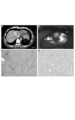
- FIG. 3 is an image of a cancer lesion by contrast CT and ICG fluorescence and a photomicrograph of the cancer lesion.
- A is an image obtained by contrast CT
- B is an intensity distribution image of near-infrared fluorescence from ICG in the liver
- C is a micrograph of a tissue section of an accessory lesion
- D is an enlarged image of a 3C micrograph.
- FIG. 4 is an image of a cancer lesion by contrast CT and ICG fluorescence and a photomicrograph of the cancer lesion.
- A is an image obtained by contrast CT
- B is an intensity distribution image of near-infrared fluorescence from ICG in the liver
- C is a micrograph of a tissue section of an accessory lesion
- D is an enlarged image of a C micrograph.
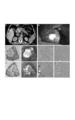
- FIG. 5 is an image of a cancer lesion by contrast CT and ICG fluorescence and a photomicrograph of the cancer lesion.
- A is an image by contrast CT
- B and C are intensity distribution images of near-infrared fluorescence from ICG in the liver
- D is a micrograph of a tissue section of a secondary lesion.
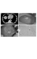
- FIG. 6 is an image of a cancer lesion by contrast CT and ICG fluorescence, a photograph of the excised cancer lesion, and a micrograph of the cancer lesion.
- A is an image by contrast CT
- B is an intensity distribution image of near-infrared fluorescence from ICG in the liver
- C and G are photographs of liver fixed with formalin
- D and H are near-infrared fluorescence from ICG in the excised liver.
- Intensity distribution images (corresponding to C and G, respectively)
- E, F, I and J are photomicrographs of the lesion tissue (F is E and J is an enlarged image of I).
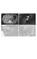
- FIG. 7 is an image of a cancer lesion by contrast CT and ICG fluorescence and a photomicrograph of the cancer lesion.
- A is an image obtained by contrast CT
- B is an intensity distribution image of near-infrared fluorescence from ICG in the liver
- C is a micrograph of a tissue section of an accessory lesion
- D is an enlarged image of a C micrograph.
- an indocyanine green-exposed organ is irradiated with indocyanine green excitation light to obtain an intensity distribution image of near-infrared fluorescence, and indocyanine green is obtained.
- a cancer lesion distribution image obtained by applying X-rays, nuclear magnetic resonance, or ultrasound to a test organ before administration is obtained.
- the test organ for acquiring an intensity distribution image of near-infrared fluorescence is a test organ of a living body to which indocyanine green is administered, preferably intravenously.
- indocyanine green those that do not form a complex with a high-density lipoprotein and are not bound to an antibody against a protein that specifically exists in a secondary lesion of cancer are particularly preferably used.
- Indocyanine green is preferably intravenously injected together with distilled water as a composition for detecting a secondary lesion of cancer.
- the content of indocyanine green in the composition for detecting a secondary lesion of cancer can be appropriately determined based on the type and degree of progression of cancer, the age and weight of a patient (patient).
- the indocyanine green excitation light irradiated to the test organ is preferably near infrared light (preferably 700 to 1000 nm, particularly 700 to 800 nm). Specifically, it is desirable to irradiate excitation light with a light emitting diode (LED) or a semiconductor laser (LD). Also, an optical filter (for example, a LowPass filter that transmits a wavelength of 800 nm or less or a bandpass filter with a center wavelength of 760 nm) is mounted on a halogen lamp of about 150 W as an excitation light source, and light from this light source is irradiated by an optical fiber But you can.
- the intensity of excitation light and the excitation time can be appropriately determined according to the amount of indocyanine green introduced, the size of the cancer lesion, and the like.
- the near-infrared fluorescence from excited indocyanine green typically has a wavelength of 800 to 900 nm (particularly 825 to 850 nm)
- the intensity of near-infrared fluorescence by an imaging means capable of imaging light of that wavelength.
- a distribution image can be acquired.
- the imaging means include a solid-state imaging device such as a CCD camera. When using a CCD camera, it is preferable to remove the infrared cut filter.
- the intensity distribution image of near-infrared fluorescence is preferably obtained for the test organ 1 to 10 days after the administration of indocyanine green (and 3 to 5 days later).
- near-infrared fluorescence may be obtained from the entire organ to be detected, and there is a possibility that the lesion cannot be distinguished from normal tissue. is there.
- near-infrared fluorescence may become weak even if it is a lesion after 10 days after an administration process.
- indocyanine green is accumulated in the neovascular site of the cancer lesion.
- new blood vessels are formed one after another, but indocyanine green is likely to leak from the newly formed blood vessel site, and it is considered that indocyanine green accumulates in the vicinity of the new blood vessels.
- the near-infrared fluorescence intensity distribution image is preferably acquired two-dimensionally or three-dimensionally over the entire target organ.
- a cancer lesion distribution image is obtained by applying X-rays, nuclear magnetic resonance, or ultrasonic waves to a test organ before administration of indocyanine green.
- the lesion detected by such imaging is the main lesion of cancer, but the size of the detectable lesion is about 5 mm in the long axis direction.
- a cancer lesion distribution image obtained by applying X-rays that is, an X-ray image (CT) is obtained by using, for example, a medical X-ray CT apparatus Aquilion TM 16 (manufactured by Toshiba Medical Systems) or a similar device. Can be taken.
- CT X-ray image
- conditions for taking an X-ray image (CT) of the liver include a tube voltage of 120 kV, a tube current of 400 mA, a rotation time of 0.5 sec / time, a pitch of 1.5, and a slice thickness of 1 mm, but are not limited thereto.
- the iodinated contrast agent include Iopamylon (registered trademark) (Bayer Chemicals) having the general name iopamidol as an active ingredient.
- 370 mg (95 mL) may be injected at an injection rate of 4 mL / second.
- the imaging delay time may be about 20 seconds for 1 phase (screening), about 30 seconds for 2 phase (scrutiny), and about 80 seconds for 3 phase (scrutiny).
- the X-ray dose is set according to the patient's physique.
- a cancer lesion distribution image obtained by applying nuclear magnetic resonance that is, a nuclear magnetic resonance image (MRI) is taken using, for example, a magnetic resonance diagnostic apparatus MAGNETOM Symphony 1.5T (manufactured by Siemens) or a similar apparatus. can do.
- the shooting procedure is not particularly limited, but for example, shooting can be performed by the following method. First, before injecting a contrast agent, a slice image in a triaxial direction of a coronal section, a sagittal section, and a transverse section is taken in a static state. Subsequently, a contrast medium is injected and dynamic imaging is performed.
- an imaging region is determined, a contrast medium is injected by bolus injection from a vein, and temporal changes are imaged in the above three-axis directions at intervals of about 10 seconds. In some cases, the image may be taken with only one axis. Finally, when sufficient time has elapsed since the injection of the contrast medium, a slice image in the triaxial direction is taken as a static contrast medium-containing image.
- dynamic imaging is particularly effective in diagnosing the quality of cancer lesions.
- a cancer lesion distribution image obtained by applying ultrasonic waves that is, an ultrasonic image can be taken using, for example, a digital ultrasonic diagnostic apparatus EUB-8500 (manufactured by Hitachi Medical Corporation) or a similar apparatus.
- EUB-8500 manufactured by Hitachi Medical Corporation
- the imaging frame rate and power level can be set by those skilled in the art according to the position and size of the subject organ to be examined.
- data on the secondary lesion area of cancer is collected. That is, data of a region that is detected in the intensity distribution image of near-infrared fluorescence but not detected in the cancer lesion distribution image is collected as cancer sub-fault region data.
- the identification of cancer sub-lesion area data is possible by superimposing the near-infrared fluorescence intensity distribution image and the cancer lesion distribution image.
- the superposition may be manual superposition or digital image superposition.
- the identification of such secondary lesion area data of cancer is performed without intervention of medical practice by a doctor. For example, by identifying the organ in which the main lesion of cancer exists from the cancer lesion distribution image and determining where the identified organ is located in the intensity distribution image of near-infrared fluorescence, the comparison of both images Is possible. That is, it is possible to find a region that is detected by the intensity distribution image of near-infrared fluorescence but not detected by the cancer lesion distribution image.
- the data collection method of the present invention is particularly useful for detecting the presence of a cancer sub-foci in an organ that cannot be detected by a cancer lesion distribution image. It can also be used to detect lesions (sub-lesions) that could not be detected in the image. According to the data collection method of the present invention, a cancer lesion (sub-lesion) having a size of less than 5 mm in the major axis direction can be detected.
- the target cancer is preferably solid cancer such as gastric cancer, esophageal cancer, colon cancer, liver cancer, etc., but it may be metastatic cancer metastasized from other organ cancers.
- liver cancer particularly hepatocellular carcinoma, is suitable as a target to which the method of the present invention is applied because of its low postoperative survival rate.
- the subject living body
- indocyanine green functions as a cancer secondary lesion detection agent. That is, indocyanine green functions as an X-ray image, MRI, an ultrasonic device, or a detection agent for detecting a secondary lesion present in an area that is not detected by visual inspection.
- the indocyanine green preferably does not form a complex with the high-density lipoprotein and does not bind to an antibody against a protein specifically present in the accessory lesion.
- This cancer secondary lesion detection agent is particularly effective for liver cancer and hepatocellular carcinoma, and is preferably used for detection 1 to 10 days after administration to a living body (human or non-human mammal). .
- FIG. 1 is a block diagram of an embodiment of a cancer secondary lesion detection apparatus that can be used in the data collection method of the present invention.
- FIG. 2 is a perspective view showing the configuration of an excitation light source unit and an imaging device used in the cancer secondary lesion detection apparatus shown in FIG.
- the cancer secondary lesion detection apparatus irradiates a test organ 20 with excitation light 10 having a predetermined wavelength, and generates an image (fluorescence image 11) of fluorescence emitted from the test organ 20. ) Is detected to detect a secondary lesion of cancer.
- indocyanine green is injected in advance from the vicinity of the lesion in the test organ 20 or from a vein. Then, the near-infrared fluorescence from the indocyanine green accumulated in the secondary lesion of the cancer is observed to detect the secondary lesion of the cancer.
- the excitation light source unit 2 includes an excitation light source unit 2 (irradiation means), an optical filter 3, an imaging device 4 (imaging means), an adjustment device 5, and an image display device 6.
- the cancer secondary lesion detection device shown in FIG. The excitation light source unit 2 includes a plurality of excitation light sources 2a and a support plate 2b on which one of the excitation light sources 2a is installed.
- the plurality of excitation light sources 2a are light sources that emit light having the same wavelength as the excitation light, and are used to irradiate the test organ 20 with the excitation light 10.
- the excitation light source 2a is two-dimensionally arranged with the central axis Ax of the excitation light source unit 2 serving as the optical axis of the present detection apparatus as a symmetry axis.
- the excitation light source 2a As described above, it is preferable to use a semiconductor laser (LD) or a light emitting diode (LED) as the excitation light source 2a. Moreover, since the light absorption band of indocyanine green is in the near infrared wavelength band, the wavelength within the wavelength band (for example, wavelength 760 nm) is appropriately selected as the wavelength of the excitation light 10 supplied from the excitation light source 2a. Used.
- LD semiconductor laser
- LED light emitting diode
- the support plate 2b is provided with an opening 2c at a central position including the central axis Ax.
- the opening 2c is for allowing the fluorescence image 11 from the test organ 20 incident from the front of the excitation light source unit 2 to pass rearward.
- the plurality of excitation light sources 2a described above are two-dimensionally arranged so as to surround the opening 2c. In such a configuration, in order to prevent the intensity distribution of the excitation light 10 irradiated to the test organ 20 from being weakened in the center due to the influence of the opening 2c, the excitation light source 2a in the vicinity of the opening 2c is prevented. It is preferable to install the optical axis inclined toward the central axis Ax.
- an optical filter 3 that transmits light in the wavelength band of the fluorescent image 11 emitted from a secondary lesion of cancer out of the light from the test organ 20 to be observed. is set up.
- an optical filter having a transmission characteristic that cuts light of a wavelength other than the fluorescent image 11 including the reflected light reflected by the test organ 20 is preferably used.
- An imaging device 4 is installed on the rear side of the excitation light source unit 2.
- the imaging device 4 is provided integrally with the excitation light source unit 2 with the optical axis Ax aligned.
- the fluorescence image 11 emitted from the fluorescent dye in the secondary lesion of the cancer excited by the excitation light 10 irradiated from the excitation light source 2a passes through the opening 2c of the support plate 2b and the optical filter 3 and is captured.
- Device 4 is reached.
- the imaging device 4 captures the incident fluorescence image 11 and outputs the obtained observation image as image data.
- the imaging device 4 for example, a CCD camera capable of acquiring a two-dimensional image is used.
- the imaging device 4 uses a device capable of imaging with high sensitivity to light in the wavelength band of the fluorescent image 11 (usually a near-infrared wavelength band because a fluorescent image of around 800 nm is targeted). It is preferable.
- the power supply for excitation light sources and the power supply for imaging devices are respectively connected as needed.
- FIG. 1 illustration of the power source and the like is omitted.
- these devices may be driven by a battery.
- the adjustment device 5 is an adjustment unit that adjusts the image data of the observation image output from the imaging device 4 automatically or manually.
- the adjusting device 5 in the present embodiment includes a luminance adjusting unit 5b and a contrast adjusting unit 5c, and adjusts the luminance and contrast of the observation image from the imaging device 4, respectively.
- the adjustment conditions of the observation image in the adjustment units 5b and 5c are instructed from the adjustment instruction unit 5a.
- the adjustment instruction unit 5a sets observation image adjustment conditions automatically or in response to an input from an observer. However, when the adjustment condition is fixed, such an adjustment instruction unit 5a may not be provided.
- a wired or wireless transmission method can be used for transmission of image data from the imaging device 4 to the adjustment device 5.
- the image display device 6 and the image recording device 7 are connected to the adjustment device 5.
- the image display device 6 displays the observation image 15 adjusted by the adjustment device 5 on the display unit 6a as an image for detecting a secondary lesion of cancer.
- a CRT monitor a liquid crystal display attached to a CCD camera that is the imaging device 4, or the like can be used.
- the image recording device 7 is a recording means for recording observation image data adjusted by the adjusting device 5.
- a video tape recorder that records an observation image on a video tape as a recording medium can be used.
- indocyanine green which is a fluorescent dye
- indocyanine Green is intravenously injected.
- a predetermined time typically 1 to 10 days after intravenous injection
- indocyanine Green emits a fluorescent image 11 in the near-infrared wavelength band from a secondary lesion of this cancer.
- the fluorescent image 11 is transmitted by the optical filter 3 and the reflected light from the test organ 20 irradiated with the excitation light 10 is cut.
- the fluorescent image 11 transmitted through the optical filter 3 is picked up by a CCD camera as the image pickup device 4, and observation image data is output from the CCD camera to the adjustment device 5.
- the adjustment device 5 adjusts the brightness and contrast of the observation image from the imaging device 4.
- an observation image 15 (including the main lesion image of cancer) including the secondary lesion image 16 of cancer is generated.
- these images are displayed on the display unit 6a of the image display device 6, whereby an intensity distribution image of near-infrared fluorescence is obtained. Further, the observation image 15 is recorded on a recording medium in the image recording device 7 as necessary.
- ICG fluorescence method A method for detecting near-infrared fluorescence obtained by irradiating excitation light of indocyanine green may be referred to as ICG fluorescence method.
- ICG 0.5 mg / kg
- ICG was injected intravenously several days before surgery. That is, in Examples 1, 2, 3, 4, and 5, ICG was intravenously administered 4 days before surgery, 4 days before surgery, 8 days before surgery, 1 day before surgery, and 4 days before surgery.
- the liver is observed using an infrared observation camera system PDE (Photodynamic Eye (trade name), manufactured by Hamamatsu Photonics), which is a secondary lesion detection apparatus for cancer and has the configuration shown in FIGS. Cell carcinoma was detected.
- Examples 1 to 4 were primary liver cancer, and Example 5 was metastatic liver cancer.
- Example 1 The case in Example 1 is a man in his 50s.
- a diagnosis by contrast-enhanced CT performed before surgery the presence of a single HCC with a diameter of 40 mm in the liver S5 / 8 area was observed.
- FIG. 3A is an image showing the result of contrast CT, and HCC is indicated by an arrow.
- FIG. 3B is an intensity distribution image of near-infrared fluorescence from ICG (measured before laparotomy and before resection) in the liver, and the arrow on the right (arrowhead) indicates a fluorescent site (secondary diameter) 5 mm in diameter in the liver S4 area.
- the larger fluorescent site indicated by the left arrow represents the main tumor site (main lesion).
- FIG. 3C shows a micrograph of a tissue section of an accessory lesion (fluorescent site with a diameter of 5 mm in the liver S4 area), and
- FIG. 3D is an enlarged image of the micrograph of FIG. 3C.
- Example 2 The case in Example 2 is a male in his 70s.
- FIG. 4A is an image showing the result of contrast CT, and HCC is indicated by an arrow.
- contrast-enhanced CT images it was diagnosed as a simple nodule type, but when laparotomy was performed and an intraoperative diagnosis was performed by PDE, a fluorescent site (adult lesion) 2 to 3 mm in diameter around the main tumor (main lesion). Since we were able to collect data on the presence of scattering, we determined the resection range including them and performed hepatectomy.
- FIG. 4A is an image showing the result of contrast CT, and HCC is indicated by an arrow.
- FIG. 4B is an intensity distribution image of near-infrared fluorescence from ICG in the liver (measured before laparotomy and before resection), and the fluorescent site indicated by the right arrow is the main tumor site (main lesion)
- Two arrows (arrowheads) indicate fluorescent sites (sub-lesions) with a diameter of 2 to 3 mm that are found around the main tumor.
- the main tumor was diagnosed as moderately differentiated HCC, and the scattered nodules (collateral foci) were satellite nodules. Diagnosed.
- FIG. 4C shows a micrograph of a tissue section of an accessory lesion (a fluorescent site with a diameter of 2 to 3 mm, which was observed around the main tumor), and
- FIG. 4D is an enlarged image of the micrograph of FIG. 4C.
- Example 3 The case in Example 3 is a man in his 60s.
- the diagnosis by contrast-enhanced CT performed before surgery the presence of a single HCC having a diameter of 25 mm was observed in the S8 area of the liver.
- FIG. 5A is an image showing a result of contrast CT, and HCC is indicated by an arrow.
- the liver surface was irregular, and it was difficult to identify the main tumor (main lesion) by intraoperative diagnosis with ultrasound, but the site of HCC (main lesion and accessory lesion) was fluorescent by intraoperative diagnosis by PDE. Since the data was collected as the site, the resection range could be easily determined.
- 5B and 5C are images of intensity distribution of near-infrared fluorescence from ICG in the liver (measured before laparotomy and before resection), and the arrows in FIG. 5B indicate the main tumor (main lesion).
- the arrow (arrowhead) indicates a fluorescent site (sub-lesion) having a diameter of 5 mm in the liver S5 area.
- a fluorescent site (sub-lesion) having a diameter of 5 mm in the liver S5 area was additionally excised.
- FIG. 5D represents a micrograph of the accessory lesion (arrowhead).
- Example 4 The case in Example 4 is a man in his 70s.
- the diagnosis by contrast-enhanced CT performed before surgery the presence of a single HCC having a diameter of 25 mm was observed in the S5 area of the liver.
- FIG. 6A is an image showing the result of contrast CT, and HCC is indicated by an arrow.
- HCC site main lesion and accessory lesion
- 6B is an intensity distribution image of near-infrared fluorescence from ICG in the liver (measured before laparotomy and before resection), and the fluorescent site indicated by the left arrow is the main tumor site (main lesion), Two arrows (arrowheads) indicate fluorescent sites (sub-lesions) with a diameter of 3 mm that are found around the main tumor.
- a plurality of 3 mm diameter fluorescent sites (sub-lesions) were additionally excised.
- the excised liver was fixed with formalin and then sliced to a thickness of 3 mm (FIGS. 6C and 6G), and the cross section was observed with PDE (FIGS. 6D and 6H).
- FIG. 6E shows a micrograph of a tissue section of an accessory lesion (fluorescent site having a diameter of 3 mm), and FIG. 6F is an enlarged image of the micrograph of FIG. 6E.
- FIG. 6H near infrared fluorescence intensity distribution image
- FIG. 6H double arrow head the light emission site
- FIG. 6I represents micrographs of tissue sections of these sites
- FIG. 6J is an enlarged image of the micrograph of FIG. 6I.
- Example 5 The case in Example 5 is a man in his 50s.
- the diagnosis by contrast-enhanced CT performed before surgery the presence of a liver tumor having a diameter of 25 mm in the liver S2 area and a diameter of 22 mm in the liver S7 area was observed.
- FIG. 7A is an image showing the result of contrast CT, and a liver tumor is indicated by an arrow.
- the liver S4 After laparotomy, in addition to the two lesions pointed out preoperatively, it was difficult to confirm and identify by palpation and intraoperative ultrasound.
- the liver S4 also had a fluorescent site with a diameter of 5 mm (adult lesion). Therefore, we determined the resection range including them and performed hepatectomy.
- FIG. 5 The case in Example 5 is a man in his 50s.
- FIG. 7B is an intensity distribution image of near-infrared fluorescence from ICG in the liver (measured before laparotomy and before excision), and an arrow (arrowhead) indicates a fluorescent site (sub-lesion) having a diameter of 5 mm. . Histological examination of the excised tissue confirmed that it was adenocarcinoma histologically and was diagnosed as colorectal liver metastasis.
- FIG. 7C shows a micrograph of a tissue section of an accessory lesion (fluorescent site having a diameter of 5 mm), and FIG. 7D is an enlarged image of the micrograph of FIG. 7C.
- minute HCC or metastatic cancer that could not be confirmed by conventional contrast CT could be found by intraoperative PDE diagnosis.
- These small HCCs or metastatic cancers have been missed by conventional resection, and this may have contributed to a reduction in 5-year recurrence-free survival.
- the above-described ICG infrared observation camera system is considered to be useful not only for detecting minute HCC or metastatic cancer during the operation, but also for determining the liver resection line and changing the surgical procedure.
Landscapes
- Health & Medical Sciences (AREA)
- Life Sciences & Earth Sciences (AREA)
- Physics & Mathematics (AREA)
- General Health & Medical Sciences (AREA)
- Pathology (AREA)
- Engineering & Computer Science (AREA)
- Veterinary Medicine (AREA)
- Public Health (AREA)
- Animal Behavior & Ethology (AREA)
- Biomedical Technology (AREA)
- Medical Informatics (AREA)
- Biophysics (AREA)
- Molecular Biology (AREA)
- Heart & Thoracic Surgery (AREA)
- Surgery (AREA)
- Nuclear Medicine, Radiotherapy & Molecular Imaging (AREA)
- Chemical & Material Sciences (AREA)
- Immunology (AREA)
- Gastroenterology & Hepatology (AREA)
- General Physics & Mathematics (AREA)
- Biochemistry (AREA)
- Analytical Chemistry (AREA)
- Radiology & Medical Imaging (AREA)
- Optics & Photonics (AREA)
- Chemical Kinetics & Catalysis (AREA)
- High Energy & Nuclear Physics (AREA)
- Epidemiology (AREA)
- Endocrinology (AREA)
- Physiology (AREA)
- Dermatology (AREA)
- Vascular Medicine (AREA)
- General Chemical & Material Sciences (AREA)
- Medicinal Chemistry (AREA)
- Organic Chemistry (AREA)
- Pharmacology & Pharmacy (AREA)
- Medicines Containing Antibodies Or Antigens For Use As Internal Diagnostic Agents (AREA)
- Investigating, Analyzing Materials By Fluorescence Or Luminescence (AREA)
- Magnetic Resonance Imaging Apparatus (AREA)
Priority Applications (4)
| Application Number | Priority Date | Filing Date | Title |
|---|---|---|---|
| CN2009801175725A CN102026582A (zh) | 2008-05-15 | 2009-05-15 | 数据收集方法 |
| EP20090746672 EP2277453A4 (en) | 2008-05-15 | 2009-05-15 | METHOD OF COLLECTING DATA |
| JP2010512032A JP5598719B2 (ja) | 2008-05-15 | 2009-05-15 | 癌の副病巣検出剤、癌の副病巣検出用組成物及び癌の副病巣検出装置 |
| KR1020107021539A KR101591119B1 (ko) | 2008-05-15 | 2009-05-15 | 데이터 수집 방법 |
Applications Claiming Priority (2)
| Application Number | Priority Date | Filing Date | Title |
|---|---|---|---|
| US5324908P | 2008-05-15 | 2008-05-15 | |
| US61/053,249 | 2008-05-15 |
Publications (1)
| Publication Number | Publication Date |
|---|---|
| WO2009139466A1 true WO2009139466A1 (ja) | 2009-11-19 |
Family
ID=41316365
Family Applications (1)
| Application Number | Title | Priority Date | Filing Date |
|---|---|---|---|
| PCT/JP2009/059059 WO2009139466A1 (ja) | 2008-05-15 | 2009-05-15 | データ収集方法 |
Country Status (6)
| Country | Link |
|---|---|
| US (2) | US8956591B2 (ko) |
| EP (1) | EP2277453A4 (ko) |
| JP (1) | JP5598719B2 (ko) |
| KR (1) | KR101591119B1 (ko) |
| CN (1) | CN102026582A (ko) |
| WO (1) | WO2009139466A1 (ko) |
Cited By (7)
| Publication number | Priority date | Publication date | Assignee | Title |
|---|---|---|---|---|
| JP2013544358A (ja) * | 2010-11-18 | 2013-12-12 | バイオリーダーズ コーポレーション | ポリ−γ−グルタミン酸と光学映像ダイの複合体を含有するセンチネルリンパ節検出用光学映像プローブ |
| JP2015126885A (ja) * | 2014-12-26 | 2015-07-09 | 国立大学法人高知大学 | 近赤外蛍光を発する医療具及び医療具位置確認システム |
| US10413619B2 (en) | 2015-05-19 | 2019-09-17 | Shimadzu Corporation | Imaging device |
| US10456040B2 (en) | 2014-09-18 | 2019-10-29 | Shimadzu Corporation | Imaging device |
| US11116454B2 (en) | 2018-07-19 | 2021-09-14 | Shimadzu Corporation | Imaging device and method |
| US11317809B2 (en) | 2017-08-29 | 2022-05-03 | Shimadzu Corporation | Imaging apparatus |
| US11419500B2 (en) | 2018-03-01 | 2022-08-23 | Shimadzu Corporation | Imaging apparatus |
Families Citing this family (5)
| Publication number | Priority date | Publication date | Assignee | Title |
|---|---|---|---|---|
| US9044142B2 (en) * | 2010-03-12 | 2015-06-02 | Carl Zeiss Meditec Ag | Surgical optical systems for detecting brain tumors |
| US20150030542A1 (en) * | 2013-07-26 | 2015-01-29 | Sunil Singhal | Methods for medical imaging |
| CN109100342A (zh) * | 2018-09-21 | 2018-12-28 | 北京大学深圳医院 | 血液中吲哚氰绿的检测装置及系统 |
| CN111134622B (zh) * | 2019-05-24 | 2021-03-02 | 四川大学华西医院 | 一种无创检测体内吲哚菁绿含量的装置 |
| CN112617825A (zh) * | 2020-12-17 | 2021-04-09 | 中国人民解放军西部战区总医院 | 一种导联电极在快速定位癫痫病灶中的应用 |
Citations (9)
| Publication number | Priority date | Publication date | Assignee | Title |
|---|---|---|---|---|
| JPH09309845A (ja) * | 1996-05-21 | 1997-12-02 | Hamamatsu Photonics Kk | 近赤外線蛍光トレーサーおよび蛍光イメージング方法 |
| JP2001299676A (ja) * | 2000-04-25 | 2001-10-30 | Fuji Photo Film Co Ltd | センチネルリンパ節検出方法および検出システム |
| JP2002095663A (ja) * | 2000-09-26 | 2002-04-02 | Fuji Photo Film Co Ltd | センチネルリンパ節光断層画像取得方法および装置 |
| JP2003290128A (ja) * | 2002-03-29 | 2003-10-14 | Olympus Optical Co Ltd | センチネルリンパ節検出方法 |
| JP2004255180A (ja) * | 1992-06-08 | 2004-09-16 | Univ Of Washington | 患者の注目部位の光学特性の変化を画像化する方法 |
| JP2004538485A (ja) * | 2001-08-09 | 2004-12-24 | ビオカム ゲーエムベーハー | 蛍光診断システム |
| WO2006003762A1 (ja) * | 2004-06-30 | 2006-01-12 | Hamamatsu Photonics K.K. | リンパ節検出装置 |
| JP2006509573A (ja) * | 2002-12-13 | 2006-03-23 | イエトメド リミテッド | 手術中に腫瘍と正常組織とを実時間で区別するのに特に有用な光学的検査方法および装置 |
| JP2007533737A (ja) | 2004-04-21 | 2007-11-22 | マーベル セラピューティクス | 撮像におけるコントラストを強調するための組成物および方法 |
Family Cites Families (8)
| Publication number | Priority date | Publication date | Assignee | Title |
|---|---|---|---|---|
| US5699798A (en) | 1990-08-10 | 1997-12-23 | University Of Washington | Method for optically imaging solid tumor tissue |
| US6671540B1 (en) * | 1990-08-10 | 2003-12-30 | Daryl W. Hochman | Methods and systems for detecting abnormal tissue using spectroscopic techniques |
| US5590660A (en) | 1994-03-28 | 1997-01-07 | Xillix Technologies Corp. | Apparatus and method for imaging diseased tissue using integrated autofluorescence |
| US5928625A (en) | 1997-03-13 | 1999-07-27 | Mallinckrodt Inc. | Method of measuring physiological function |
| CA2273609A1 (en) * | 1999-06-04 | 2000-12-04 | Resolution Pharmaceuticals Inc. | Radiopharmaceuticals and methods for imaging |
| US7394053B2 (en) * | 2004-09-09 | 2008-07-01 | Beth Israel Deaconess Medical Center, Inc. | Systems and methods for multi-modal imaging having a spatial relationship in three dimensions between first and second image data |
| WO2006079091A1 (en) * | 2005-01-24 | 2006-07-27 | Mallinckrodt Inc. | Methods of providing long-term stability to biocompatible optical dyes and bodily fluids |
| US20090041673A1 (en) * | 2007-08-03 | 2009-02-12 | Anygen Co., Ltd. | Thermally Crosslinked Contrast Agents |
-
2009
- 2009-05-14 US US12/466,085 patent/US8956591B2/en active Active
- 2009-05-15 WO PCT/JP2009/059059 patent/WO2009139466A1/ja active Application Filing
- 2009-05-15 KR KR1020107021539A patent/KR101591119B1/ko active IP Right Grant
- 2009-05-15 JP JP2010512032A patent/JP5598719B2/ja active Active
- 2009-05-15 CN CN2009801175725A patent/CN102026582A/zh active Pending
- 2009-05-15 EP EP20090746672 patent/EP2277453A4/en not_active Withdrawn
-
2014
- 2014-12-19 US US14/576,960 patent/US9717806B2/en active Active
Patent Citations (9)
| Publication number | Priority date | Publication date | Assignee | Title |
|---|---|---|---|---|
| JP2004255180A (ja) * | 1992-06-08 | 2004-09-16 | Univ Of Washington | 患者の注目部位の光学特性の変化を画像化する方法 |
| JPH09309845A (ja) * | 1996-05-21 | 1997-12-02 | Hamamatsu Photonics Kk | 近赤外線蛍光トレーサーおよび蛍光イメージング方法 |
| JP2001299676A (ja) * | 2000-04-25 | 2001-10-30 | Fuji Photo Film Co Ltd | センチネルリンパ節検出方法および検出システム |
| JP2002095663A (ja) * | 2000-09-26 | 2002-04-02 | Fuji Photo Film Co Ltd | センチネルリンパ節光断層画像取得方法および装置 |
| JP2004538485A (ja) * | 2001-08-09 | 2004-12-24 | ビオカム ゲーエムベーハー | 蛍光診断システム |
| JP2003290128A (ja) * | 2002-03-29 | 2003-10-14 | Olympus Optical Co Ltd | センチネルリンパ節検出方法 |
| JP2006509573A (ja) * | 2002-12-13 | 2006-03-23 | イエトメド リミテッド | 手術中に腫瘍と正常組織とを実時間で区別するのに特に有用な光学的検査方法および装置 |
| JP2007533737A (ja) | 2004-04-21 | 2007-11-22 | マーベル セラピューティクス | 撮像におけるコントラストを強調するための組成物および方法 |
| WO2006003762A1 (ja) * | 2004-06-30 | 2006-01-12 | Hamamatsu Photonics K.K. | リンパ節検出装置 |
Non-Patent Citations (1)
| Title |
|---|
| See also references of EP2277453A4 * |
Cited By (8)
| Publication number | Priority date | Publication date | Assignee | Title |
|---|---|---|---|---|
| JP2013544358A (ja) * | 2010-11-18 | 2013-12-12 | バイオリーダーズ コーポレーション | ポリ−γ−グルタミン酸と光学映像ダイの複合体を含有するセンチネルリンパ節検出用光学映像プローブ |
| US9623121B2 (en) | 2010-11-18 | 2017-04-18 | Bioleaders Corporation | Optical-imaging probe for detecting sentinel lymph nodes which contains a composite of poly-gamma-glutamic acid and an optical-imaging dye |
| US10456040B2 (en) | 2014-09-18 | 2019-10-29 | Shimadzu Corporation | Imaging device |
| JP2015126885A (ja) * | 2014-12-26 | 2015-07-09 | 国立大学法人高知大学 | 近赤外蛍光を発する医療具及び医療具位置確認システム |
| US10413619B2 (en) | 2015-05-19 | 2019-09-17 | Shimadzu Corporation | Imaging device |
| US11317809B2 (en) | 2017-08-29 | 2022-05-03 | Shimadzu Corporation | Imaging apparatus |
| US11419500B2 (en) | 2018-03-01 | 2022-08-23 | Shimadzu Corporation | Imaging apparatus |
| US11116454B2 (en) | 2018-07-19 | 2021-09-14 | Shimadzu Corporation | Imaging device and method |
Also Published As
| Publication number | Publication date |
|---|---|
| KR101591119B1 (ko) | 2016-02-02 |
| KR20110014136A (ko) | 2011-02-10 |
| US8956591B2 (en) | 2015-02-17 |
| EP2277453A4 (en) | 2012-07-04 |
| EP2277453A1 (en) | 2011-01-26 |
| US9717806B2 (en) | 2017-08-01 |
| CN102026582A (zh) | 2011-04-20 |
| JPWO2009139466A1 (ja) | 2011-09-22 |
| US20150104396A1 (en) | 2015-04-16 |
| US20090285760A1 (en) | 2009-11-19 |
| JP5598719B2 (ja) | 2014-10-01 |
Similar Documents
| Publication | Publication Date | Title |
|---|---|---|
| JP5598719B2 (ja) | 癌の副病巣検出剤、癌の副病巣検出用組成物及び癌の副病巣検出装置 | |
| Rosenthal et al. | The status of contemporary image-guided modalities in oncologic surgery | |
| Lee et al. | Near-infrared fluorescent image-guided surgery for intracranial meningioma | |
| Uchiyama et al. | Combined use of contrast-enhanced intraoperative ultrasonography and a fluorescence navigation system for identifying hepatic metastases | |
| Gotoh et al. | A novel image‐guided surgery of hepatocellular carcinoma by indocyanine green fluorescence imaging navigation | |
| US8865128B2 (en) | Folate targeted enhanced tumor and folate receptor positive tissue optical imaging technology | |
| RU2450832C2 (ru) | Контрастные вещества для детекции рака предстательной железы | |
| US8858914B2 (en) | Folate targeted enhanced tumor and folate receptor positive tissue optical imaging technology | |
| JP3896176B2 (ja) | 近赤外線蛍光トレーサーおよび蛍光イメージング方法 | |
| JP2006512109A (ja) | 蛍光発光を用いた、分子構造の特定技術、および身体内腔の内側に並ぶ細胞種の治療技術 | |
| US9089601B2 (en) | Pre- and intra-operative imaging of bladder cancer | |
| JP2018500338A5 (ko) | ||
| Figueiredo et al. | Intraoperative near-infrared fluorescent cholangiography (NIRFC) in mouse models of bile duct injury | |
| Tibbetts et al. | Role of advanced laryngeal imaging in glottic cancer: early detection and evaluation of glottic neoplasms | |
| He et al. | Residual cancerous lesion and vein tumour thrombus identified intraoperatively using a fluorescence navigation system in liver surgery | |
| JP5861225B2 (ja) | 被検サンプル組織体中の検体細胞の有無判別方法および装置 | |
| Grosenick et al. | Fluorescence imaging of breast tumors and gastrointestinal cancer | |
| Gao et al. | Mechanism of dynamic near-infrared fluorescence cholangiography of extrahepatic bile ducts and applications in detecting bile duct injuries using indocyanine green in animal models | |
| JP2005195379A (ja) | 腫瘍画像検出方法とその装置 | |
| WO2022033151A1 (zh) | 一种基于吲哚菁绿的荧光照相机及其应用 | |
| Ishizawa et al. | Scientific basis and clinical application of ICG fluorescence imaging: hepatobiliary cancer | |
| JP6456433B2 (ja) | 画像診断用量子ドット | |
| Miyamoto et al. | Novel color fluorescence imaging for sentinel lymph node detection in oral and oropharyngeal cancer | |
| Ikematsu et al. | Photoacoustic imaging of fresh human surgically and endoscopically resected gastrointestinal specimens | |
| Kang et al. | Noninvasive optical imaging techniques in clinical application |
Legal Events
| Date | Code | Title | Description |
|---|---|---|---|
| WWE | Wipo information: entry into national phase |
Ref document number: 200980117572.5 Country of ref document: CN |
|
| 121 | Ep: the epo has been informed by wipo that ep was designated in this application |
Ref document number: 09746672 Country of ref document: EP Kind code of ref document: A1 |
|
| WWE | Wipo information: entry into national phase |
Ref document number: 2010512032 Country of ref document: JP |
|
| ENP | Entry into the national phase |
Ref document number: 20107021539 Country of ref document: KR Kind code of ref document: A |
|
| REEP | Request for entry into the european phase |
Ref document number: 2009746672 Country of ref document: EP |
|
| WWE | Wipo information: entry into national phase |
Ref document number: 2009746672 Country of ref document: EP |
|
| NENP | Non-entry into the national phase |
Ref country code: DE |