以下、本発明の実施の形態1,2を図面を参照して説明する。
Embodiments 1 and 2 of the present invention will be described below with reference to the drawings.
[実施の形態1]
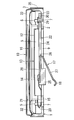
図1~8を参照して実施の形態1を説明する。図1は本発明の一実施形態の角型のフレームの斜視図である。
[Embodiment 1]
The first embodiment will be described with reference to FIGS. FIG. 1 is a perspective view of a square frame according to an embodiment of the present invention.
図1に示すフレーム1は、一枚のシート状の金属材料をプレス加工(絞り加工)して、四角形の底板2とその外側縁から直角に立ち上がる側壁3とを設けた浅い底付き四角筒状に形成すると共に、底板2に対して切り目加工および折り曲げ加工を実施し、この底板2の外側部4箇所を切り起こして、側壁3の内側に一回り小さい四角形の底付き枠状のヨーク部4を形成し、ヨーク一体型としたものである。
A frame 1 shown in FIG. 1 is a shallow bottomed rectangular tube shape in which a sheet-like metal material is pressed (drawn) to provide a square bottom plate 2 and a side wall 3 rising perpendicularly from the outer edge thereof. In addition, the bottom plate 2 is cut and bent, and four outer portions of the bottom plate 2 are cut and raised, and a rectangular bottomed frame-shaped yoke portion 4 that is slightly smaller inside the side wall 3 is formed. Is formed into a yoke-integrated type.
ヨーク部4は、側壁3の内側に所定の間隔で対向する4つのヨーク側壁5と、これら各ヨーク側壁5より内側にある底板2の中央部でなる四角形のヨーク底板6とで構成されている。
The yoke portion 4 is composed of four yoke side walls 5 facing the inside of the side wall 3 at a predetermined interval, and a rectangular yoke bottom plate 6 formed at the center of the bottom plate 2 inside each of the yoke side walls 5. .
また、フレーム1には、底板2の四隅部に形成した円形の第1開口7と、ヨーク底板6の四隅部に略L形に形成した第2開口8とを設けると共に、各ヨーク側壁5の底板2からの切り起こしにより底板2の外側部4箇所に形成された細長い四角形の第3開口9が設けられている。
In addition, the frame 1 is provided with circular first openings 7 formed at the four corners of the bottom plate 2 and second openings 8 formed in a substantially L shape at the four corners of the yoke bottom plate 6. Elongated rectangular third openings 9 formed at four locations on the outer side of the bottom plate 2 by cutting and raising from the bottom plate 2 are provided.
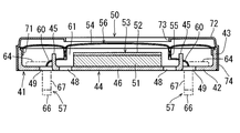
図2は図1に示した角型のフレームを使用して組み立てた角型のスピーカ(電気音響変換器の一例)の中央縦断面図、図3は同スピーカの端子部縦断面図、図4は同スピーカのバッフルと振動板および振動板リングを透明化した状態の平面図である。
2 is a central vertical sectional view of a rectangular speaker (an example of an electroacoustic transducer) assembled using the rectangular frame shown in FIG. 1, FIG. 3 is a vertical sectional view of a terminal portion of the speaker, and FIG. FIG. 3 is a plan view of the speaker with a baffle, a diaphragm and a diaphragm ring made transparent.
図2~図4に示すスピーカ10は、ヨーク底板6の上に四角柱状の永久磁石であるマグネット11を接着固定すると共に、このマグネット11の上に四角形の金属板でなるポールピース12を接着固定し、ヨーク部4とマグネット11およびポールピース12とで磁気回路13を構成している。
The speaker 10 shown in FIGS. 2 to 4 has a magnet 11 that is a square columnar permanent magnet bonded and fixed on a yoke bottom plate 6 and a pole piece 12 that is a square metal plate is bonded and fixed on the magnet 11. The yoke part 4, the magnet 11 and the pole piece 12 constitute a magnetic circuit 13.
一方、樹脂や金属フィルムからなる四角形の振動板14と四角筒状のボイスコイル15とを同心状に接着固定し、振動板14とボイスコイル15とで振動系16を構成している。
On the other hand, a rectangular diaphragm 14 made of resin or a metal film and a rectangular cylindrical voice coil 15 are bonded and fixed concentrically, and the diaphragm 14 and the voice coil 15 constitute a vibration system 16.
また、フレーム1に一対の外部接続端子17を取り付けて、各外部接続端子17の接触部18をフレーム1の底面から外部に突出させている。
Further, a pair of external connection terminals 17 are attached to the frame 1, and the contact portions 18 of the external connection terminals 17 are projected outward from the bottom surface of the frame 1.
そして、ボイスコイル15から引き出した2本のリード線19,20を各外部接続端子17に半田付けで接続すると共に、振動板14の外周縁部を側壁3に接着固定して、振動板14の下側にある磁気ギャップ21にボイスコイル15を挿入配置し、磁気回路13と振動系16をフレーム1で保持することで完成している。
Then, the two lead wires 19 and 20 drawn from the voice coil 15 are connected to the external connection terminals 17 by soldering, and the outer peripheral edge of the diaphragm 14 is bonded and fixed to the side wall 3. The voice coil 15 is inserted and disposed in the magnetic gap 21 on the lower side, and the magnetic circuit 13 and the vibration system 16 are held by the frame 1.
このように構成されたスピーカ10は、例えば携帯電話に使用されるもので、外部回路から一対の外部接続端子17を通じてボイスコイル15に電気音響信号を入力すると、磁気回路13に生じている磁界とボイスコイル15への通電で生じる磁界との相互作用で、ボイスコイル15が上下に振動し、それに伴い振動板14が上下に振動し、音を発生するものである。
The speaker 10 configured as described above is used for, for example, a cellular phone. When an electroacoustic signal is input from an external circuit to the voice coil 15 through a pair of external connection terminals 17, a magnetic field generated in the magnetic circuit 13 is generated. The voice coil 15 vibrates up and down due to the interaction with the magnetic field generated by energizing the voice coil 15, and the diaphragm 14 vibrates up and down along with it to generate sound.
以上の構成によれば、フレーム1を一枚のシート状の金属材料をプレス加工して底付き四角筒状に形成すると共に、このフレーム1の底板2を4箇所切り起こし加工して四角形の底付き枠状のヨーク部4を形成し、ヨーク一体型としたから、ヨーク一体型フレームを従来のような冷間鍛造ではなく単純なプレス加工で形成でき、スピーカ10の部品点数および組み立て工程数を削減して生産性を向上することができる。
According to the above configuration, the frame 1 is formed into a rectangular tube with a bottom by pressing a sheet of metal material, and the bottom plate 2 of the frame 1 is cut and raised at four locations to form a rectangular bottom. Since the frame-shaped yoke portion 4 is formed and the yoke is integrated, the yoke-integrated frame can be formed by simple press work instead of cold forging as in the prior art, and the number of parts of the speaker 10 and the number of assembly steps can be reduced. It can be reduced to improve productivity.
また、フレーム1が一枚のシート状の金属材料からなり、従来のようなヨークとは別体の樹脂製のフレームに比べ、厚みを抑えて必要な強度を容易に確保でき、スピーカ10のさらなる小型・薄形化が可能になる。
Further, the frame 1 is made of a single sheet-like metal material, and compared with a resin-made frame that is separate from the conventional yoke, the required strength can be easily secured with a reduced thickness, and the speaker 10 can be further secured. Small and thin.
また、各ヨーク側壁5の底板2からの切り起こしにより底板2に設けられる第3開口9を、スピーカ10の背面音孔や各外部接続端子17の外部への引き出し口として利用できるから、これらの加工工程を省略することができる。
Further, since the third opening 9 provided in the bottom plate 2 by cutting and raising from the bottom plate 2 of each yoke side wall 5 can be used as a back sound hole of the speaker 10 and an external outlet of each external connection terminal 17, Processing steps can be omitted.
また、スピーカ10の外形を変更せずに内部構造を変更することができる。すなわち、フレーム1の外形に左右されることなく、ヨーク側壁5の底板2からの切り起こし箇所・数・形状・大きさを変更可能なため、性能(形状・大きさ等)の異なる磁気回路13を構成したり、性能(大きさ)の異なる背面音孔(第3開口9)を設けることができる。これにより、スピーカ10の音響性能を容易に最適化することができる。
Also, the internal structure can be changed without changing the external shape of the speaker 10. That is, since the location, number, shape and size of the yoke side wall 5 from the bottom plate 2 can be changed without being influenced by the outer shape of the frame 1, the magnetic circuit 13 having different performance (shape, size, etc.) can be changed. Or a back sound hole (third opening 9) having different performance (size) can be provided. Thereby, the acoustic performance of the speaker 10 can be easily optimized.
本実施形態では、図2~図4に示すように、4つの第3開口9のうち、底板2の左右外側部(図4の紙面上下側部)にある2つの第3開口9を音孔として利用し、底板2の前後外側部(図4の紙面左右側部)にある2つの第3開口9を各外部接続端子17の引き出し口として利用している。
In the present embodiment, as shown in FIGS. 2 to 4, of the four third openings 9, two third openings 9 in the left and right outer portions (upper and lower sides in FIG. 4) of the bottom plate 2 are sound holes. The two third openings 9 in the front and rear outer portions (the left and right side portions of FIG. 4) of the bottom plate 2 are used as the outlets of the external connection terminals 17.
各外部接続端子17は、金属薄板を打ち抜き加工および曲げ加工して形成したもので、インサート成型により樹脂製の絶縁体22に一体に設けられている。
Each external connection terminal 17 is formed by punching and bending a thin metal plate, and is integrally provided on the resin insulator 22 by insert molding.
絶縁体22は、底板2の一つの隅部の上に重ね合わせて固定される取り付け部23と、この取り付け部23から外部接続端子17の引き出し口である第3開口9の上に延出される延出部24と、この延出部24から突出して下側の第3開口9内に嵌合される嵌合部25とを一体に形成している。
The insulator 22 extends from the mounting portion 23 onto the third opening 9 which is a lead-out port of the external connection terminal 17. The mounting portion 23 is superposed and fixed on one corner of the bottom plate 2. The extension portion 24 and a fitting portion 25 that protrudes from the extension portion 24 and fits into the lower third opening 9 are integrally formed.
外部接続端子17は、延出部24の樹脂内に埋め込まれる固定部26と、固定部26から延出されて下側の第3開口9を介してフレーム1の底面から外部に傾斜状に突出され、突出端部に下面が凸、上面が凹になる接触部18が形成された片持ち梁状のバネ片27と、延出部24の上面に一表面を略面一に露出させるように延出部24の樹脂内に埋設されて固定部26と導通接続される半田付けパッド部28とを一体に形成している。
The external connection terminal 17 is inclined from the bottom surface of the frame 1 to the outside through the fixed portion 26 embedded in the resin of the extended portion 24 and the lower third opening 9 extending from the fixed portion 26. A cantilever-like spring piece 27 having a contact portion 18 having a convex bottom surface and a concave top surface at the protruding end, and one surface exposed to the top surface of the extension portion 24. A soldering pad portion 28 that is embedded in the resin of the extending portion 24 and is electrically connected to the fixing portion 26 is integrally formed.
各リード線19,20は、ボイスコイル15から左側(図4の紙面下側)に引き出し、底板2の左外側部(図4の紙面下側)から切り起こした短手側の一方のヨーク側壁5と、底板2の前後外側部(図4の紙面左右側)から切り起こした長手側の両方のヨーク側壁5との相互間の隙間を通して、長手側の両方のヨーク側壁5の外側に引き出しており、各外部接続端子17は、それぞれ、取り付け部23をリード線19,20の引き出し側とは反対側になる底板2の右側(図4の紙面上側)の隅部の上に固定して、バネ片27を底板2の前後外側部にある第3開口9を介してフレーム1の底面から外部に突出すると共に、半田付けパッド部28をフレーム1内における長手側の両方のヨーク側壁5の外側底部に露出配置し、各リード線19,20を半田付けパッド部28に半田付けで接続するようにしている。
Each of the lead wires 19 and 20 is pulled out from the voice coil 15 to the left side (the lower side of the drawing in FIG. 4), and is cut and raised from the left outer side of the bottom plate 2 (the lower side of the drawing in FIG. 4). 5 and through the gap between the longitudinal side yoke side walls 5 cut and raised from the front and rear outer portions (left and right sides in FIG. 4) of the bottom plate 2, and pulled out of the longitudinal side yoke sidewalls 5. Each of the external connection terminals 17 has the mounting portion 23 fixed on the corner on the right side (upper side of the drawing in FIG. 4) of the bottom plate 2 on the side opposite to the lead-out side of the lead wires 19 and 20, The spring piece 27 protrudes to the outside from the bottom surface of the frame 1 through the third opening 9 in the front and rear outer portions of the bottom plate 2, and the soldering pad portion 28 is disposed outside the yoke side walls 5 on both sides of the longitudinal side in the frame 1. Exposed at the bottom, each lead wire 19, And so as to connect the 0 to solder pad portion 28 by soldering.
各外部接続端子17のフレーム1への固定は、あらかじめ取り付け部23に上下面貫通の貫通孔29を形成すると共に、取り付け部23を重ね合わせる底板2の隅部にある第1開口7の回りにバーリング加工で円筒状の立ち上げ部30を形成しておき、取り付け部23を底板2の隅部に重ね合わせる際、立ち上げ部30を貫通孔29を介して取り付け部23の下面側から上面側に貫通させ、取り付け部23の上面に突出する立ち上げ部30の端部をつぶし加工することで行っている。
Each external connection terminal 17 is fixed to the frame 1 in advance by forming a through hole 29 penetrating the upper and lower surfaces in the attachment portion 23 in advance and around the first opening 7 at the corner of the bottom plate 2 on which the attachment portion 23 is overlapped. When the cylindrical rising portion 30 is formed by burring and the mounting portion 23 is overlapped with the corner of the bottom plate 2, the rising portion 30 is connected to the upper surface side from the lower surface side of the mounting portion 23 through the through hole 29. This is done by crushing the end of the rising portion 30 protruding from the upper surface of the mounting portion 23.
図2~図4に示した外部接続端子17に代えて、図5または図6に示すような他の外部接続端子17Aまたは17Bを用いてもよい。
In place of the external connection terminal 17 shown in FIGS. 2 to 4, another external connection terminal 17A or 17B as shown in FIG. 5 or FIG. 6 may be used.
図5に示す他の外部接続端子17Aは、金属薄板を打ち抜き加工および曲げ加工して形成したもので、インサート成型により樹脂製の絶縁体22Aに一体に設けられている。
The other external connection terminal 17A shown in FIG. 5 is formed by punching and bending a thin metal plate, and is provided integrally with the resin insulator 22A by insert molding.
絶縁体22Aは、上下面貫通の貫通孔29Aを有し、底板2の一つの隅部の上に重ね合わせて固定される取り付け部23Aを形成している。
The insulator 22 </ b> A has a through-hole 29 </ b> A that penetrates the top and bottom surfaces, and forms an attachment portion 23 </ b> A that is fixed on one corner of the bottom plate 2.
外部接続端子17Aは、取り付け部23Aの樹脂内に埋め込まれる固定部(図示省略)と、この固定部の一側部から延出されての延出方向にある第3開口9を介してフレーム1の底面から外部に傾斜状に突出され、突出端部に下面が凸、上面が凹になる接触部18が形成された片持ち梁状のバネ片27Aと、取り付け部23Aの上面に一表面を略面一に露出させるように取り付け部23Aに埋設されて固定部と導通接続される半田付けパッド部28Aとを一体に形成している。
The external connection terminal 17A has a frame 1 through a fixing portion (not shown) embedded in the resin of the mounting portion 23A and a third opening 9 extending in one direction extending from one side portion of the fixing portion. A cantilever-shaped spring piece 27A formed with a contact portion 18 that protrudes outward from the bottom surface of the lens, has a bottom surface protruding at the protruding end, and a concave surface, and one surface on the top surface of the mounting portion 23A. A soldering pad portion 28A that is embedded in the attachment portion 23A and is electrically connected to the fixing portion is integrally formed so as to be substantially flush with the surface.
このような外部接続端子17Aを一対で設けるもので、各外部接続端子17Aは、それぞれ、取り付け部23Aを底板2の右側(図4の紙面上側)の隅部の上に固定して、バネ片27Aを底板2の前後外側部にある第3開口9を介してフレーム1の底面から外部に突出すると共に、半田付けパッド部28Aをフレーム1内における右側隅部の底部に露出配置し、各リード線19,20を半田付けパッド部28Aに半田付けで接続させるようにしている。
A pair of such external connection terminals 17A is provided, and each external connection terminal 17A has a mounting portion 23A fixed on the right corner (upper side of the paper in FIG. 4) of the bottom plate 2 and a spring piece. 27A protrudes outside from the bottom surface of the frame 1 through the third opening 9 in the front and rear outer portions of the bottom plate 2, and the soldering pad portion 28A is exposed at the bottom of the right corner in the frame 1 so that each lead The wires 19 and 20 are connected to the soldering pad portion 28A by soldering.
各外部接続端子17Aのフレーム1への固定は、図2~図4に示した各外部接続端子17と同じ方法で行われる。なお、図5には一対の外部接続端子17Aのうち、図4の紙面左側の外部接続端子17に対応する一方の外部接続端子17Aのみを示し、図4の紙面右側の外部接続端子17に対応する他方の外部接続端子17Aは省略しているが、一方の外部接続端子17Aとは、取り付け部23Aの外形が図4に示した各外部接続端子17と同様に対称になる他は同じ構造である。
The fixing of each external connection terminal 17A to the frame 1 is performed in the same manner as each external connection terminal 17 shown in FIGS. 5 shows only one external connection terminal 17A corresponding to the external connection terminal 17 on the left side of FIG. 4 among the pair of external connection terminals 17A, and corresponds to the external connection terminal 17 on the right side of FIG. Although the other external connection terminal 17A is omitted, it has the same structure as the one external connection terminal 17A except that the outer shape of the mounting portion 23A is symmetric like each external connection terminal 17 shown in FIG. is there.
図6に示す他の外部接続端子17Bは、コイルバネで構成したもので、インサート成型により樹脂製の絶縁体22Bに一体に設けられている。
The other external connection terminal 17B shown in FIG. 6 is constituted by a coil spring, and is provided integrally with the resin insulator 22B by insert molding.
絶縁体22Bは、底板2の一つの隅部の上に重ね合わせて固定される取り付け部23Bを形成している。
The insulator 22B forms an attachment portion 23B that is fixed on one corner of the bottom plate 2 in an overlapping manner.
コイルバネである外部接続端子17Bは、上部が取り付け部23Bの樹脂内に埋め込まれて取り付け部23Bの下面側に突出され、外部接続端子17Bの突出端部を接触部18としている。外部接続端子17Bには、取り付け部23Bの上面に一表面を略面一に露出させるように取り付け部23Bに埋設された半田付けパッド部(図示省略)が導通接続されている。
The external connection terminal 17B, which is a coil spring, has an upper portion embedded in the resin of the attachment portion 23B and protruding toward the lower surface side of the attachment portion 23B, and the protruding end portion of the external connection terminal 17B serves as a contact portion 18. A soldering pad portion (not shown) embedded in the attachment portion 23B is conductively connected to the external connection terminal 17B so that one surface is substantially flush with the upper surface of the attachment portion 23B.
このような外部接続端子17Bを一対で設けるもので、各外部接続端子17Bは、それぞれ、取り付け部23Bを底板2の右側(図4の紙面上側)の隅部の上に固定して、取り付け部23Bの下側にある第1開口7を介してフレーム1の底面から外部に突出すると共に、半田付けパッド部をフレーム1内における右側隅部の底部に露出配置し、各リード線19,20を半田付けパッド部に半田付けで接続させるようにしている。
A pair of such external connection terminals 17B is provided, and each external connection terminal 17B has an attachment portion 23B fixed on a corner on the right side (the upper side in FIG. 4) of the bottom plate 2 to attach the attachment portion 23B. 23B protrudes to the outside from the bottom surface of the frame 1 through the first opening 7 on the lower side of 23B, and the soldering pad portion is exposed at the bottom of the right corner in the frame 1, and the lead wires 19 and 20 are arranged. The solder pads are connected to the solder pads.
各外部接続端子17Bのフレーム1への固定は、外部接続端子17及び17Aと同様の方法で行うことができ、その他接着剤を用いてもよい。なお、図6には一対の外部接続端子17Bのうち、図2~図4に示した一対の外部接続端子17のうちの一方の外部接続端子17に対応する外部接続端子17Bのみを示し、他方の外部接続端子17に対応する外部接続端子17Bは省略しているが、一方の外部接続端子17Bと同じ構造である。
The fixing of each external connection terminal 17B to the frame 1 can be performed by the same method as the external connection terminals 17 and 17A, and other adhesives may be used. 6 shows only the external connection terminal 17B corresponding to one external connection terminal 17 of the pair of external connection terminals 17 shown in FIGS. 2 to 4 out of the pair of external connection terminals 17B. The external connection terminal 17B corresponding to the external connection terminal 17 is omitted, but has the same structure as the one external connection terminal 17B.
また、本実施形態では四角筒状のボイスコイル15を使用しているが、このような角型のボイスコイル15では、図7に示すように、角型に作っても巻き線のスプリングバックにより各辺部が、外面が凸、内面が凹になるように湾曲変形する場合がある。このような角型のボイスコイル15の変形に対応して、図7に示すような他のヨーク側壁5Aを底板2から切り起こしてもよい。
Further, in the present embodiment, the rectangular cylindrical voice coil 15 is used. However, in such a rectangular voice coil 15, as shown in FIG. Each side portion may be curved and deformed so that the outer surface is convex and the inner surface is concave. In response to such deformation of the rectangular voice coil 15, another yoke side wall 5A as shown in FIG.
すなわち、図7に示す他のヨーク側壁5Aは、外面が凸、内面が凹になるように湾曲させた状態で底板2から切り起こし、角型のボイスコイル15が巻き線のスプリングバックにより変形しても接触することがないようにしたものである。
That is, the other yoke side wall 5A shown in FIG. 7 is cut and raised from the bottom plate 2 in a curved state so that the outer surface is convex and the inner surface is concave, and the rectangular voice coil 15 is deformed by the spring back of the winding. Even if it does not come into contact.
さらに、本実施形態では各ヨーク側壁5の底板2からの切り起こしにより底板2に設けられる第3開口9をスピーカ10の背面音孔として利用しているが、表面実装等で背面音孔(第3開口9)が塞がれる場合は、図8に示すように、フレーム1の側壁3に背面音孔31を設けてもよい。図8に示す背面音孔31は、側壁3の短手側に設けたものである。
Further, in the present embodiment, the third opening 9 provided in the bottom plate 2 by cutting and raising from the bottom plate 2 of each yoke side wall 5 is used as the back sound hole of the speaker 10. When the 3 openings 9) are closed, a back sound hole 31 may be provided in the side wall 3 of the frame 1 as shown in FIG. The back sound hole 31 shown in FIG. 8 is provided on the short side of the side wall 3.
また、本実施形態では、図2,図3に示すように、振動板14の外周縁部に四角形の振動板リング32を接着固定し、振動板14の外周縁部を振動板リング32を介して側壁3に接着固定している。また、フレーム1の上部開口を覆う四角形のバッフル33を設けている。このバッフル33は、金属板をプレス加工して形成したもので、振動板14に対向させる正面音孔34を有すると共に、外周縁部から四角筒状の縁部35を垂下形成し、この縁部35を側壁3の外側に嵌合してフレーム1に結合している。
In the present embodiment, as shown in FIGS. 2 and 3, a rectangular diaphragm ring 32 is bonded and fixed to the outer peripheral edge of the diaphragm 14, and the outer peripheral edge of the diaphragm 14 is interposed via the diaphragm ring 32. The side wall 3 is adhesively fixed. Further, a square baffle 33 that covers the upper opening of the frame 1 is provided. The baffle 33 is formed by pressing a metal plate. The baffle 33 has a front sound hole 34 that opposes the diaphragm 14, and a rectangular cylindrical edge 35 is suspended from the outer peripheral edge. 35 is fitted to the frame 1 by being fitted to the outside of the side wall 3.
[実施の形態2]
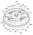
図9~図11を参照して実施の形態2を説明する。図9は本発明の一実施形態の丸型のフレームの斜視図である。
[Embodiment 2]
The second embodiment will be described with reference to FIGS. FIG. 9 is a perspective view of a round frame according to an embodiment of the present invention.
図9に示すフレーム41は、一枚のシート状の金属材料をプレス加工(絞り加工)して、円形の底板42とその外側縁から直角に立ち上がる側壁43とを設けた浅い底付き円筒状に形成すると共に、底板42に対して切り目加工および折り曲げ加工を実施し、この底板42の外側部3箇所を切り起こして、側壁43の内側に一回り小さい円形の底付き枠状のヨーク部44を形成し、ヨーク一体型としたものである。
The frame 41 shown in FIG. 9 is formed into a shallow bottomed cylindrical shape in which a sheet-like metal material is pressed (drawn) to provide a circular bottom plate 42 and a side wall 43 that rises perpendicularly from the outer edge thereof. At the same time, the bottom plate 42 is cut and bent, and three outer portions of the bottom plate 42 are cut and raised to form a round bottomed frame-shaped yoke portion 44 inside the side wall 43. The yoke is integrated and formed.
ヨーク部44は、側壁43の内側に所定の間隔で対向する3つの円弧状に湾曲したヨーク側壁45と、これら各ヨーク側壁45より内側にある底板42の中央部でなる円形のヨーク底板46とで構成されている。
The yoke portion 44 has three arcuately curved yoke side walls 45 facing the inner side of the side wall 43 at a predetermined interval, and a circular yoke bottom plate 46 formed at the center of the bottom plate 42 inside the yoke side walls 45. It consists of
また、フレーム41には、底板42の各ヨーク側壁45の相互間に形成した3つの円形の第1開口47と、ヨーク底板46の外側部に略等間隔に形成した4つの円形の第2開口48とを設けると共に、各ヨーク側壁45の底板42からの切り起こしにより底板42の外側部3箇所に略等間隔に形成された細長く円弧状に湾曲した第3開口49が設けられている。
The frame 41 has three circular first openings 47 formed between the yoke side walls 45 of the bottom plate 42 and four circular second openings formed at substantially equal intervals on the outer side of the yoke bottom plate 46. 48 and a third opening 49 that is formed in a substantially arc-like shape and is formed in the outer portion 3 of the bottom plate 42 by cutting and raising each of the yoke side walls 45 from the bottom plate 42.
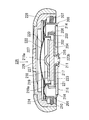
図10,図11は図9に示した丸型のフレームを使用して組み立てた丸型のスピーカ(電気音響変換器の一例)の中央縦断面図,図11は同スピーカのバッフルと振動板および振動板リングを透明化した状態の平面図である。
FIGS. 10 and 11 are central longitudinal sectional views of a round speaker (an example of an electroacoustic transducer) assembled using the round frame shown in FIG. 9, and FIG. 11 shows a baffle and a diaphragm of the speaker, It is a top view of the state which made the diaphragm ring transparent.
図10,11に示すスピーカ50は、ヨーク底板46の上に円柱状の永久磁石であるマグネット51を接着固定すると共に、このマグネット51の上に円形の金属板でなるポールピース52を接着固定し、ヨーク部44とマグネット51およびポールピース52とで磁気回路53を構成している。
10 and 11, a magnet 51, which is a cylindrical permanent magnet, is adhesively fixed on a yoke bottom plate 46, and a pole piece 52, which is a circular metal plate, is adhesively fixed on the magnet 51. The yoke portion 44, the magnet 51, and the pole piece 52 constitute a magnetic circuit 53.
一方、樹脂や金属フィルムからなる円形の振動板54と円筒状のボイスコイル55とを同心状に接着固定し、振動板54とボイスコイル55とで振動系56を構成している。
On the other hand, a circular diaphragm 54 made of resin or metal film and a cylindrical voice coil 55 are bonded and fixed concentrically, and the diaphragm 54 and the voice coil 55 constitute a vibration system 56.
また、フレーム41に一対の外部接続端子57を取り付けて、各外部接続端子57の接触部58をフレーム41の底面から外部に突出させている。
Also, a pair of external connection terminals 57 are attached to the frame 41, and the contact portions 58 of the external connection terminals 57 are projected from the bottom surface of the frame 41 to the outside.
そして、ボイスコイル55から引き出した2本のリード線59,60を各外部接続端子57に半田付けで接続すると共に、振動板54の外周縁部を側壁43に接着固定して、振動板54の下側にある磁気ギャップ61にボイスコイル55を挿入配置し、磁気回路53と振動系56をフレーム41で保持することで完成している。
Then, the two lead wires 59 and 60 drawn from the voice coil 55 are connected to the respective external connection terminals 57 by soldering, and the outer peripheral edge portion of the diaphragm 54 is bonded and fixed to the side wall 43 so that the diaphragm 54 The voice coil 55 is inserted and disposed in the magnetic gap 61 on the lower side, and the magnetic circuit 53 and the vibration system 56 are held by the frame 41.
このように構成されたスピーカ50は、例えば携帯電話に使用されるもので、外部回路から一対の外部接続端子57を通じてボイスコイル55に電気音響信号を入力すると、磁気回路53に生じている磁界とボイスコイル55への通電で生じる磁界との相互作用で、ボイスコイル55が上下に振動し、それに伴い振動板54が上下に振動し、音を発生するものである。
The speaker 50 configured as described above is used in, for example, a cellular phone. When an electroacoustic signal is input from an external circuit to the voice coil 55 through a pair of external connection terminals 57, the magnetic field generated in the magnetic circuit 53 is reduced. The voice coil 55 vibrates up and down due to the interaction with the magnetic field generated by energizing the voice coil 55, and the diaphragm 54 vibrates up and down accordingly, generating sound.
以上の構成によれば、フレーム41を一枚のシート状の金属材料をプレス加工して底付き円筒状に形成すると共に、このフレーム41の底板42を3箇所切り起こし加工して円形の底付き枠状のヨーク部44を形成し、ヨーク一体型としたから、ヨーク一体型フレームを従来のような冷間鍛造ではなく単純なプレス加工で形成でき、スピーカ50の部品点数および組み立て工程数を削減して生産性を向上することができる。
According to the above configuration, the frame 41 is formed into a cylindrical shape with a bottom by pressing one sheet-like metal material, and the bottom plate 42 of the frame 41 is cut and raised at three locations to form a circular bottom. Since the frame-shaped yoke portion 44 is formed and the yoke is integrated, the yoke-integrated frame can be formed by simple press processing instead of cold forging as in the past, and the number of parts of the speaker 50 and the number of assembly processes are reduced. And productivity can be improved.
また、フレーム41が一枚のシート状の金属材料からなり、従来のようなヨークとは別体の樹脂製のフレームに比べ、厚みを抑えて必要な強度を容易に確保でき、スピーカ50のさらなる小型・薄形化が可能になる。
Further, the frame 41 is made of a single sheet-like metal material, and the required strength can be easily ensured by suppressing the thickness as compared with a resin-made frame separate from the conventional yoke. Small and thin.
また、各ヨーク側壁45の底板42からの切り起こしにより底板42に設けられる第3開口49を、スピーカ50の背面音孔や各外部接続端子57の外部への引き出し口として利用できるから、これらの加工工程を省略することができる。
Further, since the third opening 49 provided in the bottom plate 42 by cutting and raising from the bottom plate 42 of each yoke side wall 45 can be used as a back sound hole of the speaker 50 and an external outlet of each external connection terminal 57, these Processing steps can be omitted.
また、スピーカ50の外形を変更せずに内部構造を変更することができる。すなわち、フレーム41の外形に左右されることなく、ヨーク側壁45の底板42からの切り起こし箇所・数・形状・大きさを変更可能なため、性能(形状・大きさ等)の異なる磁気回路53を構成したり、性能(大きさ)の異なる背面音孔(第3開口49)を設けることができる。これにより、スピーカ50の音響性能を容易に最適化することができる。
Also, the internal structure can be changed without changing the external shape of the speaker 50. That is, since the location, number, shape and size of the yoke side wall 45 from the bottom plate 42 can be changed without being influenced by the outer shape of the frame 41, the magnetic circuit 53 having different performance (shape, size, etc.) can be changed. Or a back sound hole (third opening 49) having different performance (size) can be provided. Thereby, the acoustic performance of the speaker 50 can be easily optimized.
本実施形態では、図11に示すように、3つの第3開口49を背面音孔や各外部接続端子57の引き出し口として利用している。
In this embodiment, as shown in FIG. 11, the three third openings 49 are used as back sound holes and outlets for the respective external connection terminals 57.
各外部接続端子57は、金属薄板を打ち抜き加工および曲げ加工して形成したもので、インサート成型により樹脂製の単一の絶縁体62に一体に設けられている。
Each external connection terminal 57 is formed by punching and bending a thin metal plate, and is provided integrally with a single insulator 62 made of resin by insert molding.
絶縁体62は、底板42の各ヨーク側壁45の相互間のうちの1箇所で重ね合わせて固定される取り付け部63と、この取り付け部63を挟む2つのヨーク側壁45の底板42からの切り起こしにより底板42に設けられた2つの第3開口49の略半分の上に、取り付け部63の両側から延出される円弧状の延出部64とを一体に形成している。
The insulator 62 is cut and raised from the bottom plate 42 of the two yoke sidewalls 45 sandwiching the attachment portion 63 and the attachment portion 63 which is fixed by being overlapped at one position between the yoke sidewalls 45 of the bottom plate 42. Thus, an arc-shaped extending portion 64 extending from both sides of the mounting portion 63 is integrally formed on substantially half of the two third openings 49 provided in the bottom plate 42.
外部接続端子57は、延出部64の樹脂内に埋め込まれる固定部66と、固定部66から下側の第3開口49に沿って円弧状に延出され、かつ下側の第3開口49を介してフレーム41の底面から外部に傾斜状に突出され、突出端部に下面が凸、上面が凹になる接触部58が形成された片持ち梁状のバネ片67と、延出部64の上面に一表面を略面一に露出させるように延出部64の樹脂内に埋設されて固定部66と導通接続される半田付けパッド部68とを一体に形成している。
The external connection terminal 57 has a fixed portion 66 embedded in the resin of the extending portion 64, and extends from the fixed portion 66 along the lower third opening 49 in an arc shape, and the lower third opening 49. A cantilever-like spring piece 67 formed with a contact portion 58 that protrudes outward from the bottom surface of the frame 41 and has a bottom surface convex and a top surface concave at the protruding end, and an extension portion 64. A soldering pad portion 68 that is embedded in the resin of the extending portion 64 and is electrically connected to the fixing portion 66 is integrally formed on the upper surface of the base plate so that one surface is substantially flush.
また、各外部接続端子57のバネ片67は、各延出部64の先端側から取り付け部63の側に向かって逆ハの字状に突出させている。
Further, the spring piece 67 of each external connection terminal 57 protrudes from the tip end side of each extension portion 64 toward the attachment portion 63 in a reverse C shape.
各リード線59,60は、ボイスコイル55から絶縁体62とは反対側になる一側(図10の紙面下側)に引き出し、各ヨーク側壁45の相互間のうち、各リード線59,60の引き出し側にある2箇所の相互間の隙間を通して、取り付け部63を挟む2つのヨーク側壁45の外側に引き出しており、各外部接続端子57は、半田付けパッド部68を取り付け部63を挟む2つのヨーク側壁45の外側底部に露出配置し、各リード線59,60を半田付けパッド部68に半田付けで接続するようにしている。
The lead wires 59 and 60 are led out from the voice coil 55 to one side opposite to the insulator 62 (the lower side in the drawing of FIG. 10), and the lead wires 59 and 60 among the yoke side walls 45 are mutually connected. Each of the external connection terminals 57 has a solder pad part 68 sandwiched between the attachment part 63 and the outside of the two yoke side walls 45 sandwiching the attachment part 63 through a gap between two places on the lead-out side. The lead wires 59 and 60 are connected to the soldering pad portion 68 by soldering so as to be exposed on the outer bottom portions of the two yoke side walls 45.
各外部接続端子57のフレーム41への固定は、あらかじめ取り付け部63に上下面貫通の貫通孔(図示省略)を形成すると共に、取り付け部63の下側にある第1開口47の回りにバーリング加工で円筒状の立ち上げ部70を形成しておき、取り付け部63を底板42の各ヨーク側壁45の相互間のうちの1箇所に重ね合わせる際、立ち上げ部70を貫通孔を介して取り付け部63の下面側から上面側に貫通させ、取り付け部63の上面に突出する立ち上げ部70の端部をつぶし加工することで行っている。
Each external connection terminal 57 is fixed to the frame 41 by previously forming a through hole (not shown) penetrating the upper and lower surfaces in the attachment portion 63 and burring around the first opening 47 on the lower side of the attachment portion 63. When the cylindrical rising portion 70 is formed and the mounting portion 63 is superposed on one of the yoke side walls 45 of the bottom plate 42, the rising portion 70 is attached to the mounting portion via the through hole. This is performed by crushing the end portion of the rising portion 70 that penetrates from the lower surface side of the 63 to the upper surface side and protrudes from the upper surface of the mounting portion 63.
本実施形態でも、各ヨーク側壁45の底板42からの切り起こしにより底板42に設けられる第3開口49をスピーカ50の背面音孔として利用しているが、表面実装等で背面音孔(第3開口49)が塞がれる場合は、第1実施形態と同様に、フレーム41の側壁43に背面音孔を設けてもよい。
Also in the present embodiment, the third opening 49 provided in the bottom plate 42 by cutting and raising each yoke side wall 45 from the bottom plate 42 is used as the back sound hole of the speaker 50. When the opening 49) is closed, a back sound hole may be provided in the side wall 43 of the frame 41 as in the first embodiment.
また、本実施形態でも、第1実施形態と同様に、振動板54の外周縁部に円形の振動板リング71を接着固定し、振動板54の外周縁部を振動板リング71を介して側壁43に接着固定している。また、フレーム41の上部開口を覆う円形のバッフル72を設けている。このバッフル72は、金属板をプレス加工して形成したもので、振動板54に対向させる正面音孔73を有すると共に、外周縁部から円筒状の縁部74を垂下形成し、この縁部74を側壁43の外側に嵌合してフレーム41に結合している。
Also in this embodiment, similarly to the first embodiment, a circular diaphragm ring 71 is bonded and fixed to the outer peripheral edge of the diaphragm 54, and the outer peripheral edge of the diaphragm 54 is connected to the side wall via the diaphragm ring 71. 43 is adhered and fixed. A circular baffle 72 that covers the upper opening of the frame 41 is provided. The baffle 72 is formed by pressing a metal plate. The baffle 72 has a front sound hole 73 opposed to the vibration plate 54, and a cylindrical edge portion 74 is suspended from the outer peripheral edge portion. Are fitted on the outside of the side wall 43 and coupled to the frame 41.
以上、実施形態1,2から明らかなように、本発明のヨーク一体型のフレームは四角や三角の角型のスピーカ10にも丸型のスピーカ50、その他オーバル型のスピーカにも対応可能なものである。
As can be seen from the first and second embodiments, the yoke-integrated frame of the present invention can be used for the square or triangular square speaker 10, the round speaker 50, and other oval speakers. It is.
以下、本発明の実施の形態3,4を図面を参照して説明する。
Hereinafter, Embodiments 3 and 4 of the present invention will be described with reference to the drawings.
[実施の形態3]
図12~図23を参照して実施の形態3を説明する。図12は本発明の一実施形態の丸型のフレームの斜視図、図13は図12のフレームを裏返しにした斜視図、図14は図12のフレームの断面図である。
[Embodiment 3]
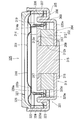
The third embodiment will be described with reference to FIGS. 12 is a perspective view of a round frame according to an embodiment of the present invention, FIG. 13 is a perspective view of the frame of FIG. 12 turned upside down, and FIG. 14 is a cross-sectional view of the frame of FIG.
図12~図14に示すフレーム201は、一枚のシート状の金属材料を絞り加工して底付き筒状に形成すると共に、内側には絞り加工による底付き枠状のヨーク部を設け、ヨーク一体型としたものである。
A frame 201 shown in FIGS. 12 to 14 is formed by drawing a sheet-like metal material into a cylindrical shape with a bottom, and is provided with a bottomed frame-like yoke portion by drawing to provide a yoke. It is an integrated type.
すなわち、ヨーク一体型フレーム201は、一枚のシート状の金属材料の中央部および周辺部をそれぞれ絞り加工して、円板状の底板の外周縁から円筒状の外側壁を立ち上げると共に、外側壁より小径な同心の内側壁であって上部に折り返し部を有する円筒状の二重壁を、底板から外側壁の内側に所定の間隔を設けて立ち上げており、二重壁の内側の壁を外周縁から立ち上げている底板中央部でなる円形のヨーク底板202と、二重壁の内側の壁でなる円筒状のヨーク側壁203とで底付き枠状のヨーク部204を形成すると共に、二重壁の外側の壁を内周縁から立ち上げ、かつ外側壁を外周縁から立ち上げている底板周縁部でなる円環形のフレーム底板205と、二重壁の外側の壁でなるフレーム内側壁206と、外側壁でなるフレーム外側壁207とでヨーク部204の周囲に底付き円環状のフレーム部208を形成している。
That is, the yoke-integrated frame 201 is formed by drawing a central portion and a peripheral portion of a single sheet-like metal material, raising a cylindrical outer wall from the outer peripheral edge of the disk-shaped bottom plate, A cylindrical double wall, which is a concentric inner wall with a smaller diameter than the wall and has a folded portion at the top, is raised from the bottom plate to the inside of the outer wall with a predetermined interval, and the inner wall of the double wall And a circular yoke bottom plate 202 formed at the center of the bottom plate rising from the outer peripheral edge and a cylindrical yoke side wall 203 formed of the inner wall of the double wall form a bottomed frame-shaped yoke portion 204, An annular frame bottom plate 205 composed of a peripheral portion of the bottom plate rising from the inner peripheral edge of the double wall and rising from the outer peripheral edge of the double wall, and an inner frame side wall formed of the outer wall of the double wall 206 and the outer wall It is forming a bottomed annular frame portion 208 around the yoke portion 204 in the side wall 207.
フレーム底板205はヨーク底板202より一段下げて形成し、ヨーク一体型フレーム1の裏面側(背面側)中央部に浅い円形の凹み209を設けると共に、フレーム外側壁207はヨーク側壁203およびフレーム内側壁206(二重壁)より高背に形成し、フレーム外側壁207のヨーク側壁203およびフレーム内側壁206(二重壁)より高位に水平な段部210を設け、この段部210より上部を下部より大径に形成している。
The frame bottom plate 205 is formed one step lower than the yoke bottom plate 202, and a shallow circular recess 209 is provided at the center of the rear surface side (back surface side) of the yoke-integrated frame 1, and the frame outer wall 207 includes the yoke side wall 203 and the frame inner wall. 206 (double wall) is formed higher than the yoke side wall 203 of the frame outer wall 207 and the horizontal inner wall 206 (double wall), and a horizontal step portion 210 is provided. It has a larger diameter.
また、ヨーク一体型フレーム201の加工工程には孔あけ加工を含み、フレーム201の底板には少なくとも2箇所以上(本実施形態では7箇所)の開口を設けるもので、ヨーク底板202の中心部の1箇所に形成するフレーム201と同心な円形の第1開口211と、ヨーク底板202の外周縁部における180°点対称な2箇所に形成する一対の第2開口212と、ヨーク底板202の外周縁部における180°点対称な2箇所であって、一対の第2開口212とは一方向に90°位置ずれした180°点対称な2箇所からその径方向外側に延設して、フレーム底板205の内周縁部における180°点対称な2箇所にまで連続的に形成し、ヨーク側壁203およびフレーム内側壁206(二重壁)における180°点対称な2箇所に切り欠き213aを形成する一対の第3開口213と、フレーム底板205における180°点対称な2箇所であって、一対の第3開口213とは一方向(一対の第3開口213の一対の第2開口212に対するずれ方向)に略45°位置ずれした180°点対称な2箇所からその径方向内側に延設して、フレーム内側壁206の上端(二重壁の折り返し部)にまで形成し、凹み209の外周壁(ヨーク底板202より下側にあるフレーム内側壁206の下部)における180°点対称な2箇所に切り欠き209aを形成する一対の第4開口214とを設けている。
Further, the processing step of the yoke-integrated frame 201 includes drilling, and the bottom plate of the frame 201 is provided with at least two openings (seven in this embodiment). A circular first opening 211 concentric with the frame 201 formed at one place, a pair of second openings 212 formed at two positions symmetrical with respect to the outer peripheral edge of the yoke bottom plate 202, and an outer peripheral edge of the yoke bottom plate 202 The frame bottom plate 205 extends from the two positions 180 symmetric about the 180 ° point in the section, and is diametrically outward from the two positions 180 symmetric about the 90 ° in one direction with respect to the pair of second openings 212. It is continuously formed up to two 180 ° point-symmetrical positions on the inner peripheral edge of the frame and cut into two 180 ° point-symmetrical positions on the yoke side wall 203 and the frame inner wall 206 (double wall). The pair of third openings 213 forming the opening 213a and two 180-point symmetrical points on the frame bottom plate 205, and the pair of third openings 213 are in one direction (a pair of second openings of the pair of third openings 213). Extending from the two 180 ° point-symmetrical positions displaced by about 45 ° to the opening 212) in the radial direction to the upper end of the inner wall 206 of the frame (the folded portion of the double wall), A pair of fourth openings 214 for forming notches 209a are provided at two 180 ° point-symmetric positions on the outer peripheral wall of the recess 209 (the lower portion of the frame inner wall 206 below the yoke bottom plate 202).
さらに、ヨーク一体型フレーム201の加工工程にはバーリング加工を含み、第1開口212をバーリング加工の下孔として用い、その下孔のまわりをバーリング加工によりヨーク底板202の裏面側に立ち上げ、ヨーク底板202の中心部から裏面側に突出する円筒状の立ち上げ部215を設けている。
Further, the processing step of the yoke-integrated frame 201 includes burring processing. The first opening 212 is used as a burring prepared pilot hole, and around the prepared hole is raised to the back side of the yoke bottom plate 202 by burring processing. A cylindrical rising portion 215 that protrudes from the center portion of the bottom plate 202 to the back surface side is provided.
図15は図12~図14に示した丸型のヨーク一体型フレームを使用して組み立てられた丸型のスピーカ本体(電気音響変換器の一例)の断面図、図16は同スピーカ本体を裏返しにした斜視図、図17は同スピーカ本体の振動板および振動板リングを透明化した状態の平面図である。
15 is a cross-sectional view of a round speaker body (an example of an electroacoustic transducer) assembled using the round yoke-integrated frame shown in FIGS. 12 to 14, and FIG. 16 is an inverted view of the speaker body. FIG. 17 is a plan view of the speaker body with the diaphragm and diaphragm ring made transparent.
図15~図17に示すスピーカ本体216は、ヨーク底板202の上に円柱状の永久磁石であるマグネット217を接着固定すると共に、このマグネット217の上に中心部にドーム状の盛り上げ部218aを有する円板状の金属板でなるポールピース218を接着固定し、ヨーク部204とマグネット217およびポールピース218とで内磁型の磁気回路219を構成している。
A speaker main body 216 shown in FIGS. 15 to 17 has a magnet 217 that is a cylindrical permanent magnet bonded and fixed on a yoke bottom plate 202, and has a dome-shaped raised portion 218a at the center on the magnet 217. A pole piece 218 made of a disk-shaped metal plate is bonded and fixed, and the yoke portion 204, the magnet 217, and the pole piece 218 constitute an inner magnet type magnetic circuit 219.
一方、樹脂や金属フィルムからなる円形の振動板220と円筒状のボイスコイル221とを同心状に接着固定し、振動板220とボイスコイル221とで振動系222を構成している。
On the other hand, a circular diaphragm 220 made of resin or metal film and a cylindrical voice coil 221 are bonded and fixed concentrically, and the diaphragm 220 and the voice coil 221 constitute a vibration system 222.
また、ヨーク一体型フレーム201の裏面側(背面側)に固定する外部接続端子である略矩形板状のプリント基板223を備えている。
Also, a substantially rectangular plate-like printed circuit board 223 which is an external connection terminal fixed to the back side (back side) of the yoke-integrated frame 201 is provided.
そして、ヨーク一体型フレーム201の裏面側(背面側)にプリント基板223を固定し、また、ヨーク底板202の上にマグネット217を接着固定すると共に、そのマグネット217の上にポールピース218を接着固定して磁気回路219を構成した後、ボイスコイル221を下側から支持して磁気回路219のヨーク側壁203とポールピース218の間に形成される円環状の磁気ギャップ219aに同軸状に配置した状態で、ボイスコイル221から引き出す2本のリード線221aのプリント基板223の一対の表面側ランド223aへの引き回し処理およびそこへのスポット溶接或いは半田付けによる接続を行い、続いて、振動板220の外周縁部をフレーム部208の段部210に上側から重ね合わせてそこに接着固定すると共に、振動板リング224を振動板220の外周縁部に上側から重ね合わせてそこに接着固定し、振動板220の外周縁部をフレーム部208の段部210に振動板リング224で上側から押えて、振動板220をヨーク一体型フレーム201の上部開口を覆うようそこに装着し、この際、ボイスコイル221の上部を振動板220の中央ドーム部と周辺エンジ部の境目に接着固定して振動系222を構成し、磁気回路219および振動系222をヨーク一体型フレーム201で一体に保持することによりスピーカ本体216を組み立てている。
Then, the printed circuit board 223 is fixed to the back side (back side) of the yoke-integrated frame 201, and the magnet 217 is bonded and fixed on the yoke bottom plate 202, and the pole piece 218 is bonded and fixed to the magnet 217. After the magnetic circuit 219 is configured, the voice coil 221 is supported from the lower side and is coaxially disposed in an annular magnetic gap 219a formed between the yoke side wall 203 of the magnetic circuit 219 and the pole piece 218. Then, the two lead wires 221a drawn from the voice coil 221 are routed to the pair of surface side lands 223a of the printed circuit board 223 and connected thereto by spot welding or soldering. The peripheral edge part is overlapped with the step part 210 of the frame part 208 from above and bonded and fixed thereto. At the same time, the diaphragm ring 224 is overlapped and fixed to the outer peripheral edge of the diaphragm 220 from the upper side, and the outer peripheral edge of the diaphragm 220 is pressed onto the step portion 210 of the frame part 208 by the diaphragm ring 224 from the upper side. Then, the diaphragm 220 is attached to cover the upper opening of the yoke-integrated frame 201. At this time, the upper portion of the voice coil 221 is bonded and fixed to the boundary between the central dome portion of the diaphragm 220 and the peripheral engine portion. The speaker body 216 is assembled by configuring the system 222 and holding the magnetic circuit 219 and the vibration system 222 integrally with the yoke-integrated frame 201.
プリント基板223のヨーク一体型フレーム201への固定は、図15および図16に示すように、プリント基板223の中心部に円形の取り付け孔223bを設け、この取り付け孔223bを介してプリント基板223をバーリング加工によりヨーク底板202の中心部から裏面側に突出して設けられた円筒状の立ち上げ部215に刺し通し、プリント基板223の両端部を一対の第4開口214に嵌め込み、プリント基板223をヨーク一体型フレーム201の裏面側に重ね合わせた状態で、プリント基板223の裏面側に突出する立ち上げ部215の先端にすり割り加工およびつぶし加工を施し、加締め固定で行われている。
As shown in FIGS. 15 and 16, the printed circuit board 223 is fixed to the yoke-integrated frame 201 by providing a circular mounting hole 223b at the center of the printed circuit board 223, and the printed circuit board 223 is attached via the mounting hole 223b. It is pierced through a cylindrical rising portion 215 provided so as to protrude from the center portion of the yoke bottom plate 202 to the back side by burring, and both ends of the printed circuit board 223 are fitted into the pair of fourth openings 214, and the printed circuit board 223 is inserted into the yoke. In a state where the integrated frame 201 is overlapped with the back surface side, the leading end of the rising portion 215 protruding to the back surface side of the printed circuit board 223 is subjected to slitting and crushing processing, and is fixed by crimping.
こうして、ヨーク一体型フレーム201の裏面側に加締め固定されたプリント基板223は、その中間部の厚みが凹み209によって吸収されると共に、両端部が一対の209aから一対の第4開口214内でフレーム部208の底部に入り込み、裏面全面がフレーム部208の裏面と略面一になる。また、図17に示すように、プリント基板223のフレーム部208の底部に入り込んだ両端部表面に一対の表面側ランド223aが形成されており、一対の表面側ランド223aを一対の第4開口214部にてフレーム部208の底部に露出配置している。さらに、プリント基板223は一方の表面側ランド223aに導通接続された一方の裏面側ランド223cおよび他方の表面側ランド223aに導通接続された他方の裏面側ランド223cを有し、この一対の裏面側ランド223cがプリント基板223の中間部裏面における取り付け孔223bを挟む2箇所に形成されている。
Thus, the printed circuit board 223 swaged and fixed to the back surface side of the yoke-integrated frame 201 is absorbed by the dent 209 in the middle portion thereof, and both end portions thereof are within the pair of fourth openings 214 from the pair of 209a. It enters the bottom of the frame portion 208 and the entire back surface is substantially flush with the back surface of the frame portion 208. As shown in FIG. 17, a pair of surface side lands 223 a are formed on the surfaces of both end portions that enter the bottom of the frame portion 208 of the printed circuit board 223, and the pair of surface side lands 223 a are paired with a pair of fourth openings 214. This part is exposed at the bottom of the frame part 208. Further, the printed circuit board 223 has one back surface land 223c electrically connected to one front surface land 223a and the other back surface land 223c electrically connected to the other front surface land 223a. Lands 223 c are formed at two locations sandwiching the attachment holes 223 b on the back surface of the intermediate portion of the printed circuit board 223.
こうして、ヨーク一体型フレーム201の一対の第4開口214を外部接続端子であるプリント基板223の位置決め孔として用いている。
Thus, the pair of fourth openings 214 of the yoke-integrated frame 201 are used as positioning holes for the printed circuit board 223 which is an external connection terminal.
また、ボイスコイル221の支持は、一対の第2開口212および一対の第3開口213を通してヨーク一体型フレーム201の裏面側からヨーク部204内に挿入されるボイスコイル支持部材である芯出しジグによって行われる。
The voice coil 221 is supported by a centering jig that is a voice coil support member inserted into the yoke portion 204 from the back side of the yoke-integrated frame 201 through the pair of second openings 212 and the pair of third openings 213. Done.
こうして、ヨーク一体型フレーム201の一対の第2開口212および一対の第3開口21を組み立て時のボイスコイル支持部材の挿入口として用いている。
Thus, the pair of second openings 212 and the pair of third openings 21 of the yoke-integrated frame 201 are used as insertion ports for the voice coil support member during assembly.
また、ボイスコイル221から引き出す2本のリード線221aのプリント基板223の一対の表面側ランド223aへの引き回し処理は、図17に示すように、ヨーク側壁203およびフレーム内側壁206(二重壁)の一対の切り欠き213aの内側でボイスコイル221から2本のリード線221aを引き出し、この2本のリード線221aを一対の切り欠き213aを通してヨーク部204からその周囲のフレーム部208に引き出した後、フレーム部208の中で一方向に延ばし、対応する表面側ランド223aへ導くことによって行われる。
Also, as shown in FIG. 17, the two lead wires 221a drawn out from the voice coil 221 are routed to the pair of surface side lands 223a of the printed board 223, as shown in FIG. The two lead wires 221a are pulled out from the voice coil 221 inside the pair of cutouts 213a, and the two lead wires 221a are pulled out from the yoke portion 204 to the surrounding frame portion 208 through the pair of cutouts 213a. This is performed by extending the frame portion 208 in one direction and guiding it to the corresponding surface side land 223a.
こうして、ヨーク一体型フレーム201のヨーク部204とその周囲にあるフレーム部208の間の隔壁であるヨーク側壁203およびフレーム内側壁206(二重壁)に設けた一対の切り欠き213a(元は一対の第3開口213)を、ボイスコイル221の2本のリード線221aをそのボイスコイル221があるヨーク部204から外部接続端子との接続部であるプリント基板223の一対の表面側ランド223aがあるフレーム208に引き出し、さらにプリント基板223の一対の表面側ランド223aに引き出すリード線引き出し口として用いている。
In this way, a pair of notches 213a (originally a pair of cutouts) provided on the yoke side wall 203 and the frame inner side wall 206 (double wall) which are partitions between the yoke part 204 of the yoke-integrated frame 201 and the frame part 208 therearound. The third opening 213), and the two lead wires 221a of the voice coil 221 have a pair of front side lands 223a of the printed circuit board 223 which is a connection part between the yoke part 204 where the voice coil 221 is located and an external connection terminal. They are used as lead wire outlets that are drawn out to the frame 208 and further drawn out to the pair of front surface lands 223a of the printed circuit board 223.
上記のように構成されたスピーカ本体216は、金属製のバッフルに装着することによって、スピーカの製品(完成品)になる。
The speaker body 216 configured as described above becomes a speaker product (finished product) by being mounted on a metal baffle.
図18は図15~図17に示したスピーカ本体をバッフルに装着した丸型のスピーカ(製品)の断面図、図19は同スピーカ(製品)の斜視図、図20は同スピーカ(製品)を裏返しにした斜視図である。
18 is a cross-sectional view of a round speaker (product) in which the speaker body shown in FIGS. 15 to 17 is mounted on a baffle, FIG. 19 is a perspective view of the speaker (product), and FIG. 20 is a perspective view of the speaker (product). It is the perspective view turned upside down.
図18~図20に示すスピーカ225は、スピーカ本体216のヨーク一体型フレーム201を天付き円筒状の深いバッフル226に圧入固定し、スピーカ本体216の略全高をバッフル226内に装着して構成したもので、スピーカ225の裏面側(背面側)にはプリント基板223が水平に配置され、プリント基板223の裏面(裏面側ランド223c)がバッフル226の下端より僅かにスピーカ225の裏面側(背面側)へ突出されている。また、スピーカ本体216の振動板220とバッフル226の天部の間には振動系222が十分なストロークで振動できる間隙が形成されている。バッフル226は振動板220の中央ドーム部と対向する天部に多数の小孔227でなるスピーカ225の正面音孔を設けている。また、バッフル226の外側面にはシリコンゴムなどの弾性材料のモールド成形によってスピーカ225の音響抵抗補正用のカバー228が一体に形成されている。
The speaker 225 shown in FIGS. 18 to 20 is configured by pressing and fixing the yoke-integrated frame 201 of the speaker main body 216 to the deep cylindrical baffle 226 having a ceiling, and mounting the substantially entire height of the speaker main body 216 in the baffle 226. Therefore, the printed circuit board 223 is horizontally arranged on the back surface side (back surface side) of the speaker 225, and the back surface (back surface land 223 c) of the printed circuit board 223 is slightly behind the lower end of the baffle 226 (back surface side). ). In addition, a gap is formed between the diaphragm 220 of the speaker body 216 and the top of the baffle 226 so that the vibration system 222 can vibrate with a sufficient stroke. The baffle 226 is provided with a front sound hole of the speaker 225 including a large number of small holes 227 in the top portion facing the central dome portion of the diaphragm 220. A cover 228 for correcting the acoustic resistance of the speaker 225 is integrally formed on the outer surface of the baffle 226 by molding an elastic material such as silicon rubber.
また、図21は図15~図17に示したスピーカ本体を他のバッフルに装着した他の丸型のスピーカ(製品)の断面図、図22は同他のスピーカ(製品)の斜視図、図23は同他のスピーカ(製品)を裏返しにした斜視図である。
21 is a cross-sectional view of another round speaker (product) in which the speaker body shown in FIGS. 15 to 17 is mounted on another baffle, and FIG. 22 is a perspective view of the other speaker (product). 23 is a perspective view in which the other speaker (product) is turned upside down.
図21~図23に示す他のスピーカ229は、縁付きで浅い蓋状のバッフル230をスピーカ本体216のヨーク一体型フレーム201に嵌着して構成したもので、他のスピーカ229の裏面側(背面側)にはプリント基板223が水平に配置されている。また、スピーカ本体216の振動板220とバッフル230の天部の間には振動系222が十分なストロークで振動できる間隙が形成されている。バッフル230は振動板220の中央ドーム部と対向する天部に多数の小孔231でなる他のスピーカ229の正面音孔を設けている。
The other speaker 229 shown in FIGS. 21 to 23 is configured by fitting a baffle 230 having a shallow edge with a frame to the yoke-integrated frame 201 of the speaker main body 216. The other speaker 229 has a rear surface side (rear surface). The printed circuit board 223 is horizontally disposed on the side. In addition, a gap is formed between the diaphragm 220 of the speaker body 216 and the top of the baffle 230 so that the vibration system 222 can vibrate with a sufficient stroke. The baffle 230 is provided with a front sound hole of another speaker 229 made up of a large number of small holes 231 in a top portion facing the central dome portion of the diaphragm 220.
上記のように構成されたスピーカ225は、例えばヘッドホンやイヤホンのスピーカ(ドライバー)として使用され、上記のように構成された他のスピーカ229は、例えばPC,PDA,デジタルカメラ,デジタルビデオカメラのスピーカとして使用されるもので、各スピーカ225,229は、外部回路からプリント基板223の一対の裏面側ランド223c,それと導通接続された一対の表面側ランド223a,それに接続された2本のリード線221aを通じてボイスコイル221に電気音響信号を入力すると、磁気回路219に生じている磁界とボイスコイル221への入力信号で生じる磁界との相互作用で、ボイスコイル221が上下に振動し、それに伴い振動板220が上下に振動し、正面音孔227,231から音を発生するものである。
The speaker 225 configured as described above is used as, for example, a speaker (driver) of headphones or earphones, and the other speaker 229 configured as described above is a speaker of a PC, PDA, digital camera, digital video camera, or the like. Each speaker 225, 229 is connected to a pair of backside lands 223c of the printed circuit board 223 from an external circuit, a pair of front side lands 223a electrically connected to the lands 223a, and two lead wires 221a connected thereto. When an electroacoustic signal is input to the voice coil 221 through the magnetic coil 221, the voice coil 221 vibrates up and down due to the interaction between the magnetic field generated in the magnetic circuit 219 and the magnetic field generated by the input signal to the voice coil 221. 220 vibrates up and down and generates sound from front sound holes 227 and 231 Is shall.
この際、振動板220背面側のヨーク一体型フレーム201の内圧、すなわち音響抵抗を一対の第2開口212の大きさで調整(補正)している。
At this time, the internal pressure of the yoke-integrated frame 201 on the back side of the diaphragm 220, that is, the acoustic resistance is adjusted (corrected) by the size of the pair of second openings 212.
こうして、ヨーク一体型フレーム201の一対の第2開口212を各スピーカ255,229の音響抵抗補正用の背面音孔として用いている。
Thus, the pair of second openings 212 of the yoke-integrated frame 201 are used as back sound holes for correcting the acoustic resistance of the speakers 255 and 229.
以上、本実施形態によれば、フレーム201は、一枚のシート状の金属材料を絞り加工して底付き筒状に形成すると共に、底板には少なくとも2箇所以上の開口を設け、内側には絞り加工による底付き枠状のヨーク部204を設け、ヨーク一体型としたから、ヨーク一体型フレーム201を従来のような冷間鍛造ではなく単純なプレス加工で形成でき、スピーカ225,229の部品点数および組み立て工程数を削減して生産性を向上することができる。
As described above, according to the present embodiment, the frame 201 is formed by drawing a sheet-like metal material into a cylindrical shape with a bottom, and providing at least two openings on the bottom plate, Since the bottomed frame-shaped yoke portion 204 is formed by drawing and is made into a yoke-integrated type, the yoke-integrated frame 201 can be formed by simple press processing instead of cold forging as in the past, and the components of the speakers 225 and 229 Productivity can be improved by reducing the number of points and assembly steps.
ヨーク一体型フレーム201が一枚のシート状の金属材料からなり、従来のようなヨークとは別体の樹脂製のフレームに比べ、厚みを抑えて必要な強度を容易に確保でき、スピーカ225,229のさらなる小型・薄形化が可能になる。
The yoke-integrated frame 201 is made of a single sheet-like metal material, and the required strength can be easily ensured by suppressing the thickness as compared with a conventional resin frame separate from the yoke. 229 can be further reduced in size and thickness.
また、一対の第2開口212からなる背面音孔を設け(この背面音孔は必要に応じて数や大きさを変更される。)、一対の第4開口からなる外部接続端子位置決め孔214を設け、一対の第2開口および一対の第3開口からなり、組み立て時のボイスコイル支持部材の挿入口212および213を設け、一対の第3開口213からなり、ボイスコイル221のリード線221aを外部接続端子223との接続部223aに引き出す切り欠き213aを設け、単一の第1開口(ヨーク一体型フレーム201の中心孔)からなるバーリング加工用の下孔211を設け、バーリング加工とそれにより形成される立ち上げ部215の端部をつぶすつぶし加工によって、前記フレーム201に外部接続端子223を結合している。このようにヨーク一体型フレーム201は単純なプレス加工によって形成できる開口によって様々な機能を付加することができる。
Also, a back sound hole made up of a pair of second openings 212 is provided (the number and size of the back sound holes can be changed as necessary), and an external connection terminal positioning hole 214 made up of a pair of fourth openings is provided. Provided with a pair of second openings and a pair of third openings, provided with voice coil support member insertion ports 212 and 213 at the time of assembly, and composed of a pair of third openings 213, with the lead wire 221a of the voice coil 221 being externally provided A notch 213a to be drawn out is provided in a connection portion 223a with the connection terminal 223, and a lower hole 211 for burring made of a single first opening (a central hole of the yoke-integrated frame 201) is provided. The external connection terminal 223 is coupled to the frame 201 by a crushing process for crushing the end of the raised portion 215. As described above, the yoke-integrated frame 201 can be provided with various functions by the openings that can be formed by simple press working.
[実施の形態4]
続いて、図24~図33を参照して実施の形態4を説明する。図24は本発明の一実施形態の角型のフレームの斜視図、図25は図24のフレームを裏返した斜視図、図26は図24のフレームの(a)平面図,(b)B-B断面図,(c)C-C断面図である。
[Embodiment 4]
Next, Embodiment 4 will be described with reference to FIGS. 24 is a perspective view of a rectangular frame according to an embodiment of the present invention, FIG. 25 is a perspective view of the frame of FIG. 24 turned upside down, FIG. 26 is a plan view of the frame of FIG. 24, and FIG. It is B sectional drawing, (c) CC sectional drawing.
図24~図26に示すフレーム301は、一枚のシート状の金属材料を絞り加工して底付き筒状に形成すると共に、内側には絞り加工による底付き枠状のヨーク部を設け、ヨーク一体型としたものである。
The frame 301 shown in FIGS. 24 to 26 is formed by drawing a single sheet-like metal material into a bottomed cylindrical shape, and provided with a bottomed frame-like yoke portion by drawing, It is an integrated type.
すなわち、ヨーク一体型フレーム301は、一枚のシート状の金属材料の中央部および周辺部をそれぞれ絞り加工して、矩形板状の底板の外周縁から矩形筒状の外側壁を立ち上げると共に、外側壁より一回り小形な同心の内側壁であって上部に折り返し部を有する矩形筒状の二重壁を、底板から外側壁の内側に所定の間隔を設けて立ち上げており、二重壁の内側の壁を外周縁から立ち上げている底板中央部でなる矩形板状のヨーク底板302と、二重壁の内側の壁でなる矩形筒状のヨーク側壁303と底付き枠状のヨーク部304を形成すると共に、二重壁の外側の壁を内周縁から立ち上げ、かつ外側壁を外周縁から立ち上げている底板周縁部でなる円環形のフレーム底板305と、二重壁の外側の壁でなるフレーム内側壁306と、外側壁でなるフレーム外側壁307とでヨーク部304の周囲に底付き円環状のフレーム部308を形成している。
That is, the yoke-integrated frame 301 is formed by drawing a central portion and a peripheral portion of a single sheet-like metal material to raise a rectangular cylindrical outer wall from the outer peripheral edge of the rectangular plate-shaped bottom plate, A rectangular cylindrical double wall, which is a concentric inner wall that is slightly smaller than the outer wall and has a folded portion at the top, is erected from the bottom plate to the inside of the outer wall with a predetermined interval. A rectangular plate-shaped yoke bottom plate 302 formed at the center of the bottom plate rising from the outer peripheral edge of the inner wall, a rectangular cylindrical yoke side wall 303 formed of the inner wall of the double wall, and a frame-shaped yoke portion with a bottom 304, and an annular frame bottom plate 305 formed by a bottom plate peripheral edge rising from the inner peripheral edge of the double wall and rising from the outer peripheral edge of the double wall; Frame inner wall 306 made of walls and outside Forming a bottomed annular frame portion 308 around the yoke portion 304 by the frame outer wall 307 made of.
また、ヨーク側壁303およびフレーム内側壁306は上部の折り返し部からのヨーク側壁303の長さ寸法をフレーム内側壁306の長さ寸法をより長くして、ヨーク部304をフレーム部308より一段下げて形成すると共に、フレーム外側壁307の高さ寸法はヨーク側壁303の高さ寸法と略同じに形成して、フレーム外側壁307をフレーム内側壁306より高背に形成している。
Further, the yoke side wall 303 and the frame inner side wall 306 are made such that the length of the yoke side wall 303 from the upper folded portion is made longer than that of the frame inner side wall 306, and the yoke part 304 is lowered by one step from the frame part 308. At the same time, the height of the frame outer wall 307 is formed to be substantially the same as the height of the yoke side wall 303 so that the frame outer wall 307 is formed taller than the frame inner wall 306.
また、ヨーク一体型フレーム301の加工工程には孔あけ加工を含み、フレーム301の底板には少なくとも2箇所以上(本実施形態では5箇所)の開口を設けるもので、ヨーク底板302の中央部の1箇所に形成するフレーム301と同心な矩形の第1開口309と、ヨーク底板302の四隅からフレーム底板305の四隅に連続的に形成し、ヨーク側壁303およびフレーム内側壁306(二重壁)の四隅に切り欠き310aを形成する4つの第2開口310とを設けている。なお、ヨーク一体型フレーム301はその中心を対称点とする180°点対称に形成されている。
Further, the processing step of the yoke-integrated frame 301 includes drilling, and the bottom plate of the frame 301 is provided with at least two openings (in this embodiment, five openings). A rectangular first opening 309 concentric with the frame 301 formed in one place, and continuously formed from the four corners of the yoke bottom plate 302 to the four corners of the frame bottom plate 305, the yoke side wall 303 and the frame inner side wall 306 (double wall) Four second openings 310 for forming notches 310a are provided at the four corners. The yoke-integrated frame 301 is formed with a 180 ° point symmetry with the center as the symmetry point.
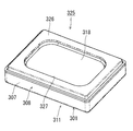
図27は図24~図26に示した角型のヨーク一体型フレームを使用して組み立てられた角型のスピーカ本体(電気音響変換器の一例)の底面図、図28は図27のD-D断面図、図29は図27のE-E断面図、図30は同スピーカ本体のボイスコイルの組み立て図である。
FIG. 27 is a bottom view of a rectangular speaker body (an example of an electroacoustic transducer) assembled using the rectangular yoke-integrated frame shown in FIGS. 24 to 26, and FIG. FIG. 29 is a sectional view taken along line D, FIG. 29 is a sectional view taken along line EE in FIG. 27, and FIG. 30 is an assembled view of a voice coil of the speaker body.
図27および図28に示すスピーカ本体311は、ヨーク底板302の上に矩形環状の永久磁石であるマグネット312を接着固定すると共に、このマグネット312の上に矩形環状の金属板でなるポールピース313を接着固定し、ヨーク部304とマグネット312およびポールピース313とで内磁型の磁気回路314を構成している。
27 and 28, a magnet 312 that is a rectangular annular permanent magnet is bonded and fixed on a yoke bottom plate 302, and a pole piece 313 that is a rectangular annular metal plate is provided on the magnet 312. The yoke part 304, the magnet 312 and the pole piece 313 constitute an inner magnet type magnetic circuit 314 which is bonded and fixed.
また、磁気回路314は、積層状態のヨーク底板302とマグネット312およびポールピース313にある第1開口309とマグネット内孔312aおよびポールピース内孔313aに外部接続端子である矩形柱状のプリント基板315を嵌合し、このプリント基板315によって、ヨーク底板302とマグネット312およびポールピース313の芯合わせを行うと共に、ヨーク底板302の裏面側(背面側)に突出するプリント基板315の下端部から水平方向外側に張り出す下側係合部316と、ポールピース313の上面側に突出するプリント基板315の上端部から水平方向外側に張り出す上側係合部317で積層状態のヨーク底板302とマグネット312およびポールピース313を挟み、これらヨーク底板302とマグネット312およびポールピース313を一体に加締め固定している。なお、図27に示すように、ポールピース内孔313aは、ポールピース313の上側係合部317と係合する上面を上側係合部317の厚み分だけ後退させるような段付きとし、ポールピース313の上面とプリント基板315の上面とを略面一にすることが好ましい。
In addition, the magnetic circuit 314 includes a rectangular columnar printed board 315 as an external connection terminal in the laminated yoke bottom plate 302, the magnet 312 and the first opening 309 in the pole piece 313, the magnet inner hole 312a and the pole piece inner hole 313a. With this printed circuit board 315, the yoke bottom plate 302, the magnet 312 and the pole piece 313 are aligned, and the outer side in the horizontal direction from the lower end of the printed circuit board 315 protruding to the back side (back side) of the yoke bottom plate 302. A yoke bottom plate 302, a magnet 312 and a pole in a laminated state with a lower engaging portion 316 protruding to the upper side and an upper engaging portion 317 protruding outward in the horizontal direction from the upper end portion of the printed circuit board 315 protruding to the upper surface side of the pole piece 313. The piece 313 is sandwiched between the yoke bottom plate 302 and the mug. The Tsu bets 312 and pole piece 313 are caulked integrally fixed. As shown in FIG. 27, the pole piece inner hole 313a is stepped so that the upper surface of the pole piece 313 engaged with the upper engagement portion 317 is retracted by the thickness of the upper engagement portion 317. It is preferable that the upper surface of 313 and the upper surface of the printed circuit board 315 are substantially flush.
プリント基板315の上面には一対の上面側ランド(図示省略)が形成され、プリント基板315の下面には一方の上面側ランドと導通接続される一方の下面側ランド315aおよび他方の上面側ランドと導通接続される他方の下面側ランド315aが形成されている。
A pair of upper surface lands (not shown) are formed on the upper surface of the printed circuit board 315, and one lower surface side land 315a and the other upper surface side land that are electrically connected to one upper surface side land are formed on the lower surface of the printed circuit board 315. The other lower surface side land 315a to be conductively connected is formed.
一方、樹脂や金属フィルムからなる矩形の振動板318と矩形筒状のボイスコイル319とを樹脂や金属フィルムからなるボイスコイル・ボビン兼ダンパー320を介して同心状に接着固定し、振動板318とボイスコイル319とで振動系321を構成している。
On the other hand, a rectangular diaphragm 318 made of resin or metal film and a rectangular cylindrical voice coil 319 are concentrically bonded and fixed via a voice coil / bobbin / damper 320 made of resin or metal film. The voice coil 319 constitutes a vibration system 321.
図30に示すように、ボイスコイル・ボビン兼ダンパー320は、ボイスコイル319を外嵌する矩形筒状のボビン部320aと、ボビン部320aの上端から水平方向内側に張り出す振動板接着片部320bと、ボビン部320aの下端から水平方向外側に張り出す幅の狭いボイスコイル接着部320cと、ボイスコイル接着部320cの外側に所定の間隙を設けて配置する矩形環状の基板部320dと、基板部320dの内側四隅とボイスコイル接着部320cの四隅の間に設けるS字形の断面形状を有する4つの可撓片であるダンパー部320eを一体に形成しており、ボイスコイル319をボビン部320aに外嵌し、ボイスコイル319の内周面とボビン部320aの外周面を接着固定すると共に、ボイスコイル319の下端面とボイスコイル接着部320cの上面を接着固定した状態で、ボイスコイル319に装着されている。
As shown in FIG. 30, the voice coil / bobbin / damper 320 includes a rectangular cylindrical bobbin part 320a for fitting the voice coil 319, and a diaphragm adhesive piece part 320b extending inward in the horizontal direction from the upper end of the bobbin part 320a. A narrow voice coil adhesive portion 320c that protrudes outward in the horizontal direction from the lower end of the bobbin portion 320a, a rectangular annular substrate portion 320d that is disposed with a predetermined gap outside the voice coil adhesive portion 320c, and a substrate portion Damper portions 320e, which are four flexible pieces having an S-shaped cross-sectional shape provided between the inner four corners of 320d and the four corners of the voice coil bonding portion 320c, are integrally formed, and the voice coil 319 is attached to the bobbin portion 320a. The inner periphery of the voice coil 319 and the outer periphery of the bobbin portion 320a are bonded and fixed, and the lower end surface of the voice coil 319 The upper surface of the voice coil bonding portion 320c in a state being adhered and fixed, is mounted on the voice coil 319.
振動板318の外周縁部には裏側から振動板リング322が接着固定され、ボイスコイル・ボビン兼ダンパー320の基板部320dの外周縁部にも裏側から基板リング323が接着固定されている。
The diaphragm ring 322 is bonded and fixed to the outer peripheral edge of the diaphragm 318 from the back side, and the substrate ring 323 is bonded and fixed to the outer peripheral edge of the substrate part 320d of the voice coil / bobbin / damper 320 from the back side.
そして、図17に示すように、ヨーク一体型フレーム201のヨーク部304に磁気回路314を構成すると共に、プリント基板315を固定した後、ボイスコイル319に装着されているボイスコイル・ボビン兼ダンパー320の4つのダンパー部320eを、ヨーク側壁303およびフレーム内側壁306(二重壁)の四隅に形成されている切り欠き310aに上から嵌め込みながら、ボイスコイル・ボビン兼ダンパー320の基板部320dをフレーム部308内に挿入すると共に、ボイスコイル・ボビン兼ダンパー320のボビン部320aおよびボイスコイル319を、磁気回路314のヨーク側壁303とポールピース313の間に形成される矩形環状の磁気ギャップ314aに挿入し、ボイスコイル・ボビン兼ダンパー320の基板リング323をフレーム底板305に接着固定し、ボイスコイル319をボイスコイル・ボビン兼ダンパー320を介して磁気回路314の磁気ギャップ314aに同軸状に配置した状態で、ボイスコイル319から引き出す2本のリード線319aプリント基板315の一対の上面側ランドへの引き回し処理およびそこへのスポット溶接或いは半田付けによる接続を行い、続いて、ボイスコイル・ボビン兼ダンパー320の基板部320dの上から基板リング323の上に矩形環状のスペーサ324を重ね合わせた後、そのスペーサ324の上に振動板318の振動板リング322を重ね合わせて、振動板318をヨーク一体型フレーム301の上部開口を覆うようそこに装着し、この際、ボイスコイル・ボビン兼ダンパー320のボイスコイル接着部320cを振動板318の中央ドーム部と周辺エンジ部の境目に接着固定して振動系321を構成し、磁気回路314および振動系321をヨーク一体型フレーム301で一体に保持することによりスピーカ本体311を組み立てている。
Then, as shown in FIG. 17, the magnetic circuit 314 is formed on the yoke portion 304 of the yoke-integrated frame 201, and the printed circuit board 315 is fixed, and then the voice coil / bobbin / damper 320 mounted on the voice coil 319. The four damper portions 320e are fitted into the notches 310a formed at the four corners of the yoke side wall 303 and the frame inner side wall 306 (double wall), while the board portion 320d of the voice coil / bobbin / damper 320 is framed. In addition to being inserted into the portion 308, the bobbin portion 320a of the voice coil / bobbin / damper 320 and the voice coil 319 are inserted into a rectangular annular magnetic gap 314a formed between the yoke side wall 303 of the magnetic circuit 314 and the pole piece 313. Voice coil, bobbin and damper 32 The two substrate rings 323 are bonded and fixed to the frame bottom plate 305, and the two voice coils 319 are pulled out from the voice coil 319 in a state of being coaxially arranged in the magnetic gap 314a of the magnetic circuit 314 via the voice coil / bobbin / damper 320. The lead wire 319a is routed to a pair of upper surface lands and connected by spot welding or soldering, followed by the substrate ring from above the substrate portion 320d of the voice coil / bobbin / damper 320. After the rectangular annular spacer 324 is overlaid on the H.323, the diaphragm ring 322 of the diaphragm 318 is overlaid on the spacer 324 so that the diaphragm 318 covers the upper opening of the yoke-integrated frame 301. At this time, voice coil bobbin and damper 320 The vibration coil 321 is formed by bonding and fixing the voice coil bonding portion 320c to the boundary between the central dome portion and the peripheral edge portion of the diaphragm 318, and the magnetic circuit 314 and the vibration system 321 are integrally held by the yoke integrated frame 301. Thus, the speaker body 311 is assembled.
ボイスコイル319から引き出す2本のリード線319aのプリント基板315の一対の上面側ランドへの引き回し処理は、図30に示すように、ボイスコイル・ボビン兼ダンパー320の振動板接着片部320bにおける180°点対称の2箇所に形成された一対の凹み部320fの外側でボイスコイル319から2本のリード線319aを引き出し、この2本のリード線319aを一対の凹み部320fの上を通してプリント基板315の一対の上面側ランドへ導くことにより行われる。ボイスコイル・ボビン兼ダンパー320のボイスコイル接着部320cは一対の凹み部320f以外の部分で振動板318の中央ドーム部と周辺エンジ部の境目に接着固定され、一対の凹み部320f(非接着部)でボイスコイル319の2本のリード線319aの挿通孔が形成されている。
The two lead wires 319a drawn out from the voice coil 319 are routed to the pair of upper surface lands of the printed circuit board 315, as shown in FIG. 30, 180 in the diaphragm adhesive piece 320b of the voice coil / bobbin / damper 320. Two lead wires 319a are pulled out from the voice coil 319 outside the pair of recesses 320f formed at two points symmetrical with respect to the point, and the two lead wires 319a are passed over the pair of recesses 320f and the printed circuit board 315. This is performed by guiding to a pair of upper surface side lands. The voice coil bonding portion 320c of the voice coil / bobbin / damper 320 is bonded and fixed to the boundary between the central dome portion of the diaphragm 318 and the peripheral engine portion at portions other than the pair of recess portions 320f, and a pair of recess portions 320f (non-bonding portions). ), Insertion holes for two lead wires 319a of the voice coil 319 are formed.
上記のように構成されたスピーカ本体311は、金属製のバッフルに装着することによって、スピーカの製品(完成品)になる。
The speaker main body 311 configured as described above becomes a speaker product (finished product) by being mounted on a metal baffle.
図31は図27,図28に示したスピーカ本体をバッフルに装着した角型のスピーカ(製品)の断面図、図32は同スピーカ(製品)の斜視図、図33は同スピーカ(製品)を裏返しにした斜視図である。
31 is a cross-sectional view of a rectangular speaker (product) in which the speaker body shown in FIGS. 27 and 28 is mounted on a baffle, FIG. 32 is a perspective view of the speaker (product), and FIG. 33 is the speaker (product). It is the perspective view turned upside down.
図31~図33に示すスピーカ325は、縁付きで浅い蓋状のバッフル326をスピーカ本体311のヨーク一体型フレーム301に嵌着して構成したもので、スピーカ325の裏面側(背面側)にはプリント基板315の下面側ランド315aが露出配置されている。また、スピーカ本体325の振動板318とバッフル326の天部の間には振動系321が十分なストロークで振動できる間隙が形成されている。バッフル326は振動板318の中央ドーム部と対向する天部に単一の大きな孔でなるスピーカ325の正面音孔327を設けている。
A speaker 325 shown in FIG. 31 to FIG. 33 is configured by fitting a baffle 326 having a shallow edge with a frame to a yoke-integrated frame 301 of the speaker main body 311. A lower surface side land 315a of the printed circuit board 315 is exposed. Further, a gap is formed between the diaphragm 318 of the speaker body 325 and the top of the baffle 326 so that the vibration system 321 can vibrate with a sufficient stroke. The baffle 326 is provided with a front sound hole 327 of a speaker 325 formed of a single large hole in a top portion facing the central dome portion of the diaphragm 318.
上記のように構成されたスピーカ325は、例えばPC,PDA,デジタルカメラ,デジタルビデオカメラのスピーカとして使用されるもので、スピーカ325は、外部回路からプリント基板315の一対の裏面側ランド315a,それと導通接続された一対の上面側ランド,それに接続された2本のリード線319aを通じてボイスコイル319に電気音響信号を入力すると、磁気回路314に生じている磁界とボイスコイル319への入力信号で生じる磁界との相互作用で、ボイスコイル319が上下に振動し、それに伴い振動板318が上下に振動し、正面音孔327から音を発生するものである。
The speaker 325 configured as described above is used as, for example, a speaker of a PC, PDA, digital camera, or digital video camera. The speaker 325 is connected to a pair of backside lands 315a of the printed circuit board 315 from an external circuit. When an electroacoustic signal is input to the voice coil 319 through the pair of conductively connected upper surface lands and the two lead wires 319a connected thereto, a magnetic field generated in the magnetic circuit 314 and an input signal to the voice coil 319 are generated. Due to the interaction with the magnetic field, the voice coil 319 vibrates up and down, and the vibration plate 318 vibrates up and down accordingly, generating sound from the front sound hole 327.
この際、ボイスコイル・ボビン兼ダンパー320はボイスコイル319が正確なピストン運動(振動)を行えるようにそれを正しい位置に保持しているが、4つのダンパー部320eでボビン部320aを下側から支えるので、新たにダンパーの組み込みスペースを確保する必要がなく、小型のスピーカ325の薄さを損なうことなく、耐入力性能を向上することができる。
At this time, the voice coil / bobbin / damper 320 holds the voice coil 319 in a correct position so that the piston movement (vibration) can be accurately performed, but the four damper portions 320e hold the bobbin portion 320a from the lower side. Since it is supported, it is not necessary to secure a new installation space for the damper, and input resistance can be improved without impairing the thinness of the small speaker 325.
また、それぞれのダンパー部320eの間で空気が流通し、ボイスコイル・ボビン兼ダンパー320自体には通気性が不要であり、しかもダンパー部320eがボビン部320aを下側から支えるので、ボビン320aが振動板318と一体に形成されているか別体であるかにかかわらず、ダンパー部320eをボビン部320aと一体に形成でき、小型のスピーカ325の製造コストの上昇を抑えて、耐入力性能を向上することができる。
In addition, air flows between the respective damper portions 320e, and the voice coil / bobbin / damper 320 itself does not need air permeability, and the damper portion 320e supports the bobbin portion 320a from below, so that the bobbin 320a Regardless of whether it is formed integrally with the diaphragm 318 or a separate body, the damper part 320e can be formed integrally with the bobbin part 320a, suppressing an increase in manufacturing cost of the small speaker 325 and improving input resistance performance. can do.
基板部320dで4つのダンパー部320eの先端部を相互に連結すると、ダンパー部320eでボビン部320aを下側から支える際の安定性が増すとともに、ダンパー部320eのヨーク一体型フレーム301への装着作業性もよく、量産性を高めることができる。
When the tip portions of the four damper portions 320e are connected to each other by the substrate portion 320d, stability when the bobbin portion 320a is supported from the lower side by the damper portion 320e is increased, and the damper portion 320e is attached to the yoke-integrated frame 301. Workability is good and mass productivity can be improved.
以上、本実施形態によれば、フレーム301は、一枚のシート状の金属材料を絞り加工して底付き筒状に形成すると共に、底板には少なくとも2箇所以上の開口を設け、内側には絞り加工による底付き枠状のヨーク部304を設け、ヨーク一体型としたから、ヨーク一体型フレーム301を従来のような冷間鍛造ではなく単純なプレス加工で形成でき、スピーカ325の部品点数および組み立て工程数を削減して生産性を向上することができる。
As described above, according to the present embodiment, the frame 301 is formed by drawing a sheet-like metal material into a cylindrical shape with a bottom, and at least two openings are provided on the bottom plate, and on the inner side. Since the bottomed frame-shaped yoke portion 304 is provided by drawing, and the yoke is integrated, the yoke-integrated frame 301 can be formed not by cold forging as in the prior art but by simple press processing, and the number of parts of the speaker 325 and Productivity can be improved by reducing the number of assembly steps.
ヨーク一体型フレーム301が一枚のシート状の金属材料からなり、従来のようなヨークとは別体の樹脂製のフレームに比べ、厚みを抑えて必要な強度を容易に確保でき、スピーカ325のさらなる小型・薄形化が可能になる。
The yoke-integrated frame 301 is made of a single sheet-like metal material, and the required strength can be easily secured by reducing the thickness compared to a conventional resin frame separate from the yoke. Further reduction in size and thickness is possible.
また、第2開口310を背面音孔として利用でき、第1開口309を外部接続端子位置決め孔として利用でき、さらに、第2開口310からなる切り欠き310aによって4つのダンパー部320eでボビン部320aを下側から支えるボイスコイル・ボビン兼ダンパー320を採用することができる。
Further, the second opening 310 can be used as a back sound hole, the first opening 309 can be used as an external connection terminal positioning hole, and the bobbin portion 320a can be formed by four damper portions 320e by a notch 310a formed by the second opening 310. A voice coil / bobbin / damper 320 supported from below can be employed.