WO2009139166A1 - アンテナ装置 - Google Patents
アンテナ装置 Download PDFInfo
- Publication number
- WO2009139166A1 WO2009139166A1 PCT/JP2009/002105 JP2009002105W WO2009139166A1 WO 2009139166 A1 WO2009139166 A1 WO 2009139166A1 JP 2009002105 W JP2009002105 W JP 2009002105W WO 2009139166 A1 WO2009139166 A1 WO 2009139166A1
- Authority
- WO
- WIPO (PCT)
- Prior art keywords
- ground
- ground region
- antenna
- antenna device
- boundary
- Prior art date
- Legal status (The legal status is an assumption and is not a legal conclusion. Google has not performed a legal analysis and makes no representation as to the accuracy of the status listed.)
- Ceased
Links
Images





Classifications
-
- H—ELECTRICITY
- H01—ELECTRIC ELEMENTS
- H01Q—ANTENNAS, i.e. RADIO AERIALS
- H01Q9/00—Electrically-short antennas having dimensions not more than twice the operating wavelength and consisting of conductive active radiating elements
- H01Q9/04—Resonant antennas
- H01Q9/30—Resonant antennas with feed to end of elongated active element, e.g. unipole
- H01Q9/42—Resonant antennas with feed to end of elongated active element, e.g. unipole with folded element, the folded parts being spaced apart a small fraction of the operating wavelength
-
- H—ELECTRICITY
- H01—ELECTRIC ELEMENTS
- H01Q—ANTENNAS, i.e. RADIO AERIALS
- H01Q1/00—Details of, or arrangements associated with, antennas
- H01Q1/27—Adaptation for use in or on movable bodies
- H01Q1/32—Adaptation for use in or on road or rail vehicles
- H01Q1/3208—Adaptation for use in or on road or rail vehicles characterised by the application wherein the antenna is used
- H01Q1/3233—Adaptation for use in or on road or rail vehicles characterised by the application wherein the antenna is used particular used as part of a sensor or in a security system, e.g. for automotive radar, navigation systems
- H01Q1/3241—Adaptation for use in or on road or rail vehicles characterised by the application wherein the antenna is used particular used as part of a sensor or in a security system, e.g. for automotive radar, navigation systems particular used in keyless entry systems
-
- H—ELECTRICITY
- H01—ELECTRIC ELEMENTS
- H01Q—ANTENNAS, i.e. RADIO AERIALS
- H01Q1/00—Details of, or arrangements associated with, antennas
- H01Q1/48—Earthing means; Earth screens; Counterpoises
Definitions
- the present invention relates to an antenna device suitable for wireless communication technology such as a keyless operation system for automobiles.
- antenna devices using linear elements have been studied for the purpose of wireless communication such as automobile keyless operation systems.
- a monopole antenna in which a wire element is arranged with a length of 1/4 of an antenna operating wavelength with respect to a ground plane is generally used.
- this monopole antenna is large and high as a whole, an inverted L-type antenna has been developed in which the monopole antenna is bent in the middle to reduce the size and height.
- the reactance portion determined by the length of the horizontal portion of the antenna element parallel to the ground plane is capacitive and has a large value. It was difficult. For this reason, a so-called inverted-F antenna has been devised in order to facilitate matching between the antenna element and the 50 ⁇ feed line.
- This inverted F-type antenna is provided with a stub that connects a ground plane and a radiating element near a feeding point provided in the middle of the antenna element. As a result, it becomes easy to cancel the capacitive property of the reactance unit and match with the 50 ⁇ feed line.
- Patent Document 1 discloses an antenna element that is applied to a foldable portable wireless device, but is bent so as to be orthogonal to a flexible flat cable disposed on a printed wiring board and connected to the printed wiring board.
- An inverted F-type antenna having been proposed. In this inverted F type antenna, the antenna element is also folded in the direction perpendicular to the printed wiring board.
- the polarization (vertical / horizontal polarization) of the antenna is designed with respect to the main polarization required under the usage conditions and depends on this. For this reason, it is difficult to cope with polarization improvement with the same antenna shape. For this reason, a method of changing the design of the antenna shape in order to improve the polarization can be considered, but since it depends on the size of the housing, there is a limit to the change in design and it is difficult from the cost aspect such as mold production. There are many cases.
- the present invention has been made in view of the above-described problems, and even when the installation conditions are changed, the antenna can improve the polarization by using the same antenna, the substrate, etc., and can achieve high gain and downsizing.
- An object is to provide an apparatus.
- the antenna device of the present invention includes a first ground region formed of a conductor provided with a feeding point electrically connected to a feeding unit of a wireless circuit, and a part of the outer periphery of the first ground region. Except for the second ground region formed of a conductor along the outer periphery, the boundary between the first ground region and the second ground region, and electrically connected to the feeding point.
- This antenna device includes a ground connection portion that locally and electrically connects the first ground region and the second ground region, and the antenna element rises from the first ground region, And an element portion extending right above the second ground region from the upper end portion of the raised portion, so that the high frequency flowing through the antenna element, the first ground region, and the second ground region according to the local connection position
- the current can be adjusted, and the polarization of the entire antenna can be improved. That is, it is possible to provide a plurality of divided ground regions and improve the characteristics with respect to a desired polarization without changing the antenna element from the arrangement relationship between the connection position and the antenna element.
- the “boundary” refers to a portion where the first ground region and the second ground region are not electrically connected (electrically separated).
- this “boundary” is a region or space in which the conductor of the first ground region and the conductor of the second ground region are not connected to each other, and between the first ground region and the second ground region. It refers to the electrical insulation range intervening. Further, the phrase “provided with the above-mentioned“ ground connection portion that is electrically connected locally ”” refers to a location where the first ground region and the second ground region are electrically connected across the “boundary”. This indicates that there is a (ground connection).
- a base material provided with a ground pattern divided into the first ground region and the second ground region is provided.
- the ground pattern provided on the base material is often large and integrated from the viewpoint of improving the antenna gain. Therefore, in the present invention, a boundary for efficiently dividing the ground pattern of the base material is provided for the antenna element, and an efficient connection method is used to adjust the high-frequency current flowing through the antenna element and the ground pattern. Thus, the polarization of the entire antenna can be improved.
- the antenna device includes a first base material provided with the first ground region, and a second base material provided with the second ground region, A base material and the second base material are installed across the boundary. That is, in this antenna device, since the first base material and the second base material are installed with a boundary therebetween, the first ground region and the second ground region are provided on separate base materials. Therefore, it is possible to easily replace one with another shape and install it. For example, it is possible to easily adopt various forms by using one as a general-purpose substrate and the other as a replacement substrate.
- the boundary is orthogonal to the element portion in a plan view from above the first ground region and the second ground region at at least one location. And That is, in this antenna device, the boundary is orthogonal to the element portion in plan view from above the first ground region and the second ground region at at least one location, so that the current distribution is most effectively achieved. Adjustment is possible.
- the boundary divides the first ground region and the second ground region in the vicinity of the feeding point. That is, in this antenna device, since the boundary separates the first ground region and the second ground region in the vicinity of the feeding point, the current distribution can be adjusted more strongly.
- the ground connection portion is provided in the vicinity of the feeding point. That is, in this antenna device, since the ground connection portion is provided in the vicinity of the feeding point, when the main polarization is a horizontal polarization, the effect of improving the horizontal polarization can be obtained more strongly.
- the ground connection portion is provided at a far position farthest from the feeding point. That is, in this antenna device, since the ground connection portion is provided at the farthest position farthest from the feeding point, when the main polarization is the vertical polarization, the effect of improving the vertical polarization can be obtained more strongly. it can.
- the ground connection portion is provided at an intermediate position of the boundary. That is, in this antenna device, since the ground connection portion is provided at the middle position of the boundary, when both horizontal polarization and vertical polarization are required, a high improvement effect of both polarizations can be obtained. Can do.
- the antenna device includes a ground connection portion that locally electrically connects the first ground region and the second ground region, and the antenna element rises from the first ground region. And an element portion extending directly above the second ground region from the upper end of the rising portion, so that the antenna element, the first ground region, and the second ground according to the local connection position.
- the high-frequency current flowing in the region can be adjusted, and the polarization of the entire antenna can be improved. That is, even when the installation conditions are changed, the polarization can be improved and the gain can be increased and the size can be reduced without changing the antenna element from the arrangement relationship between the connection position and the antenna element. Therefore, the antenna device of the present invention is suitable for any one of a reception antenna device, a transmission antenna device, and a transmission / reception antenna device used in a radio communication system mounted on an automobile or the like, particularly a keyless operation system.
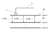
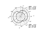
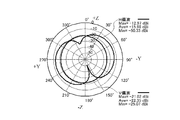
- 1st Embodiment of the antenna device which concerns on this invention, it is a simple top view which shows an antenna device. In 1st Embodiment, it is a simple perspective view which shows an antenna device. In 1st Embodiment, it is explanatory drawing like the equivalent circuit which shows an antenna apparatus. In 1st Embodiment, it is a graph which shows a radiation pattern at the time of providing a ground connection part in the vicinity position of a feeding point. In 1st Embodiment, it is a graph which shows a radiation pattern at the time of providing a ground connection part in the far position of a feeding point.
- 1st Embodiment it is a graph which shows the radiation pattern at the time of providing a ground connection part in the intermediate position of a boundary.
- it is a graph which shows a radiation pattern at the time of providing a ground connection part in three places of the vicinity position of a feeding point, a distant position, and the intermediate position of a boundary.
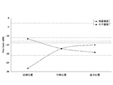
- it is a graph which compares and shows the maximum gain of a horizontal polarization and a vertical polarization with respect to the installation position of a ground connection part.
- 2nd Embodiment of the antenna device which concerns on this invention, it is a simple top view which shows an antenna device.
- the antenna device is a reception antenna device, a transmission antenna device, or a transmission / reception antenna device used in a wireless communication system mounted on, for example, an automobile, particularly a keyless operation system.
- a first ground region 5A formed of a conductor such as a copper foil provided with a feeding point 1 electrically connected to a 50 ⁇ feeding line (not shown) (a feeding portion of a wireless circuit)
- a second ground region 5B formed of a conductor such as copper foil along the outer periphery except for a part of the outer periphery of the first ground region 5A, and the first ground region 5A and the second ground region 5B, the antenna element 3 electrically connected to the feeding point 1 and erected on the first ground region 5A, the first ground region 5A and the second ground region 5B It includes a ground connecting portion 6 for locally electrically connected to.
- this antenna device is electrically connected to the base material 2 provided with the ground pattern 5 divided into the first ground region 5A and the second ground region 5B, the feeding point 1 and the antenna element 3.
- a matching circuit unit 4 that is provided on the substrate 2 and matches the reactance between the antenna element 3 and the feeder line.
- this antenna device includes a base material 2 provided with a feed point 1 to which a 50 ⁇ feed line (not shown) is electrically connected and a base member 2 that is electrically connected to the feed point 1 and stands on the base material 2.
- the keyless operation system is a keyless operation key that is installed on the main body of the car and the key when the driver or other person is carrying a key with a wireless communication function and approaches the wireless operating range.
- locking / unlocking operation so-called keyless entry system
- the base material 2 is, for example, a wiring board or a circuit board, and a wireless communication circuit, an electronic control unit (ECU), and the like (not shown) including the matching circuit unit 4 are formed on the upper surface and the lower surface.
- the antenna element 3 may be attached to the side opposite to the surface on which the electronic control unit of the substrate 2 is mounted.
- the antenna element 3 is 1/4 of the antenna operating wavelength or a length of 1 / integer length of copper wire, copper-coated wire, copper alloy wire (for example, brass) aluminum wire, aluminum-coated wire, aluminum alloy wire, etc.
- the thickness of the line is set according to the desired characteristics.
- the shape of a wire can mention circular, a rectangle, a polygon, etc. in cross-sectional shape. In consideration of bending, the cross section is preferably circular.
- the antenna element 3 may be one in which the outer periphery of the above-described conductive material (wire) is covered with an insulating layer.
- the antenna element 3 includes a rising portion 3a that rises from the first ground region 5A, and an element portion 3b that extends from the upper end of the rising portion 3a to the position immediately above the second ground region 5B. That is, the antenna element 3 includes a rising portion 3a that rises from the base material 2, and an element portion 3b that is bent from the upper end portion of the rising portion 3a and extends in an arbitrary direction within a plane parallel to the base material 2.
- the element portion 3b according to the present embodiment extends in one direction from the upper end portion of the rising portion 3a in a parallel plane with respect to the base member 2, and then bends or curves in the middle, and then returns along the opposite direction of the one direction. It is an open element formed in a substantially U-shape.
- the element portion 3b may extend in an arbitrary direction after extending from the first ground region 5A directly above the second ground region 5B, but it is easy to form the antenna and stabilize the antenna characteristics. From the viewpoint of properties and the like, it is preferable to form the film so as to extend in an arbitrary direction within a plane parallel to the substrate 2 as described above.
- the ground pattern 5 is divided into the first ground region 5A and the second ground region 5B at the boundary 7 which is a dividing line on the substrate 2, and the ground regions 5A and 5B are separated from each other.
- a ground connection portion 6 that is electrically connected locally is provided.
- it is divided into a first ground area 5A for analog circuits and a second ground area 5B for digital circuits.
- the second ground region 5 ⁇ / b> B is arranged along the outer periphery excluding a part of the outer periphery of the first ground region 5 ⁇ / b> A (the upper side and the right side in FIG. 1).
- the second ground region 5B is disposed so as not to be completely surrounded by opening at least a part of the outer periphery of the first ground region 5A.
- the ground pattern 5 is divided into a plurality of locations, it is desirable to secure as large an area as possible for each of the ground regions 5A and 5B.
- the boundary 7 is a line or a band that electrically divides the ground pattern 5 into a first ground region 5A and a second ground region 5B except for a portion that is locally electrically connected by the ground connection portion 6. It is a non-pattern part. Further, the first ground region 5A and the second ground region 5B are divided by the boundary 7 into a shape as shown in FIG. 1 according to the shape of the base material 2, but for example, the second ground region 5B. May be divided into other shapes such as a rectangular shape by the boundary 7.
- the boundary 7 intersects the element portion 3b in plan view from above the first ground region 5A and the second ground region 5B.
- the boundary 7 is orthogonal to the element portion 3b in a plan view from above the first ground region 5A and the second ground region 5B at at least one place, and the ground pattern in the vicinity of the feeding point 1 5 is preferably divided.
- the boundary 7 is orthogonal to the substantially U-shaped element portion 3b at two locations in the plan view.
- the matching circuit unit 4 has a circuit configuration in which one or a plurality of ⁇ -type LC circuits or T-type circuits including a plurality of inductances L or capacitors C are provided between the feeding point 1 and the antenna element 3. Yes.
- This matching circuit unit 4 has a function corresponding to a part for matching from a feeding point to a stub in a conventional inverted-F antenna.
- the ground connection portion 6 is provided at least in one location according to the required polarization.
- the ground connection portion 6 is provided in the vicinity 6A of the feeding point 1 and the main polarization is changed.
- it is provided at a far position 6B farthest from the feeding point 1, and when both horizontal polarization and vertical polarization are required, it is provided at an intermediate position 6C of the boundary 7.
- the near and far positions at the connection position of the ground connection portion 6 refer to the distance from the feeding point 1 electrically connected to the antenna element 3 on the boundary 7.
- the ground connection portion 6 uses commonly used passive elements such as resistors, capacitors, and inductors. In addition, flexible adjustment is also possible by using a variable resistor, a variable capacitor, a variable inductor, or the like as the ground connection portion 6. Moreover, you may employ
- the horizontal polarization is the main polarization as the radiation pattern, and the figure 8 directivity and the maximum gain is -11.63 dBi.
- the vertical polarization has a low maximum gain of ⁇ 28.13 dBi.
- FIG. 5 shows the result of measuring the radiation pattern in the horizontal plane with respect to the base material 2 when the ground connection portion 6 is provided at the remote position 6B of the feeding point 1.
- FIG. 5 shows the result of measuring the radiation pattern in the horizontal plane with respect to the base material 2 when the ground connection portion 6 is provided at the remote position 6B of the feeding point 1.
- the vertical polarization becomes the main polarization as the radiation pattern, and the main polarization is changed as compared with the case where the ground connection portion 6 is provided in the vicinity position 6A.
- the horizontal polarization remains in the figure eight directivity, but the maximum gain is -19.28 dBi.
- the vertical polarization which is the main polarization, has a maximum gain of -15.01 dBi, which is 13 dB higher than when the ground connection portion 6 is provided in the vicinity 6A.
- the result of having measured the radiation pattern about the case where the ground connection part 6 is provided in the intermediate position 6C of the boundary 7 is shown in FIG.
- the vertical and horizontal polarizations are almost the same as the radiation pattern, and the maximum gain is -17 dBi omnidirectional.
- the gain can be adjusted for vertical polarization, horizontal polarization, or both polarizations, thereby improving the polarization. Is possible.
- the result of having measured the radiation pattern about the case where the ground connection part 6 is connected in all three places of the said near position 6A, the said far position 6B, and the said intermediate position 6C is shown in FIG.
- the polarization with which the maximum gain is obtained that is, the horizontal polarization with the directivity of the figure 8 when electrically connected at the neighboring position 6A shown in FIG. 4
- the maximum gain is -21.02 dBi, which is a favorable result.
- the high-frequency current (current distribution) flowing through the antenna element 3 and the ground pattern 5 is adjusted by the combination of the connection positions of the ground regions 5A and 5B (installation position of the ground connection portion 6), thereby improving the polarization of the entire antenna. be able to.
- FIG. 1 is a result of extracting the maximum gain of each horizontal / vertical polarization for each radiation pattern from FIG. 4 to FIG. 6 and comparing the position of the ground connection portion 6.
- the horizontal polarization is deteriorated as the position of the ground connection portion 6 is farther from the vicinity of the feeding point 1
- the vertical polarization is deteriorated from the vicinity of the feeding point 1 of the vertical polarization. The farther away, the better.
- the position of the ground connection portion 6 is provided at a position 6A in the vicinity of the feeding point 1 when the main polarization is desired to be horizontal polarization, and when the main polarization is desired to be the vertical polarization, When it is provided at the far position 6B and both polarizations are required, the polarization can be improved by providing it at the middle position 6C of the boundary 7.
- FIG. 8 shows a result of comparison with respect to the radiation pattern on the horizontal plane with respect to the base material 2, but in the case of radiation patterns on other surfaces, the relationship of FIG. 8 may be reversed.
- the antenna device of this embodiment includes the ground connection portion 6 that locally electrically connects the first ground region 5A and the second ground region 5B, and the antenna element 3 includes the first ground region 5B.
- the antenna element includes the rising portion 3a rising from the region 5A and the element portion 3b extending from the upper end portion of the rising portion 3a to directly above the second ground region 5B.
- 3 and the ground pattern 5 can be adjusted, and the polarization of the entire antenna can be improved. That is, a plurality of ground regions 5A and 5B are provided, and the characteristics can be improved with respect to a desired polarization without changing the antenna element 3 from the arrangement relationship between the connection position and the antenna element 3. It becomes possible.
- the ground pattern 5 provided on the substrate 2 is often large and integrated from the viewpoint of improving the antenna gain. Therefore, in this embodiment, the boundary 7 for efficiently dividing the ground pattern 5 of the base material 2 is provided with respect to the antenna element 3, and the efficiency is increased in order to adjust the high-frequency current flowing through the antenna element 3 and the ground pattern 5.
- the polarization of the entire antenna can be improved.
- the boundary 7 is orthogonal to the element portion 3b in a plan view from above the first ground region 5A and the second ground region 5B at least at one place, the current distribution is most effectively adjusted. Is possible. Furthermore, since the boundary 7 divides the ground pattern 5 in the vicinity of the feeding point 1, the current distribution can be adjusted more strongly.
- the ground connection portion 6 when the ground connection portion 6 is provided in the vicinity of the feeding point 1, when the main polarization is a horizontal polarization, the effect of improving the characteristics can be obtained more strongly. Further, when the ground connection portion 6 is provided at a farthest position farthest from the feeding point 1, when the main polarization is a vertical polarization, the effect of improving the vertical polarization can be obtained more strongly. Further, when the ground connection portion 6 is provided at an intermediate position of the boundary 7, when both the horizontally polarized wave and the vertically polarized wave are required, a high improvement effect of both polarized waves can be obtained.
- the difference between the second embodiment and the first embodiment is that, in the first embodiment, the first ground region 5A and the second ground region 5B separated from each other at the boundary 7 on one base material 2 are separated.
- the first base material 22A provided with the first ground region 25A and the second ground region 25B are provided.
- the second base material 22B is provided, and the first base material 22A and the second base material 22B are installed with the boundary 27 interposed therebetween.
- the antenna device of the second embodiment has a rectangular first base 22A and a concave shape arranged along the other three sides except for one side of the outer periphery of the first base 22A. And a second base material 22B. That is, the antenna device according to the second embodiment includes a rectangular first ground region 25A formed on the first base material 22A and a part of the outer periphery of the first ground region 25A except for the outer periphery. And a concave second ground region 25B formed on the second base material 22B.
- the boundary 27 that divides the first ground region 25A and the second ground region 25B is not a dividing line on the base material, but a gap between the first base material 22A and the second base material 22B. It is an area.
- the first base material 22A and the second base material 22B are installed with the boundary 27 interposed therebetween, the first ground region 25A and the second ground region 25B It is possible to easily replace one of them with another shape by installing them on separate substrates. For example, it is possible to easily adopt various forms by using one as a general-purpose substrate and the other as a replacement substrate.
- the ground pattern 5 is formed on the surface of the base material 2, but a multilayer substrate may be employed as the base material when designing an actual wireless circuit.
- the ground pattern 5 may be designed in any layer such as an inner layer pattern.
- the ground pattern 5 is preferably designed on the component surface or solder surface of the surface of the substrate.
- the antenna element 3 was formed with the conductor wire, such as a copper wire, you may form with another conductor thing.
- SYMBOLS 1 Feeding point, 2,22A, 22B ... Base material, 3 ... Antenna element, 3a ... Startup part, 3b ... Element part, 5 ... Ground pattern, 5A, 25A ... 1st ground area, 5B, 25B ... 1st 2 ground regions, 6 ... ground connection, 6A ... near position, 6B ... far position, 6C ... intermediate position, 7, 27 ... boundary
Landscapes
- Engineering & Computer Science (AREA)
- Computer Security & Cryptography (AREA)
- Radar, Positioning & Navigation (AREA)
- Remote Sensing (AREA)
- Details Of Aerials (AREA)
- Variable-Direction Aerials And Aerial Arrays (AREA)
- Waveguide Aerials (AREA)
Abstract
Description
すなわち、従来のアンテナでは、様々な設置条件に変更しようとした場合、アンテナの偏波(垂直/水平偏波)は、使用条件で必要とされる主偏波に対して設計されてこれに依存するため、同一のアンテナ形状では偏波改善の対応が困難であった。このため、偏波を改善するためにアンテナ形状を設計変更する方法が考えられるが、筐体の大きさに依存するため設計変更にも限界があると共に金型作製等のコスト面からも困難な場合が多い。そのため、金属板を設置して強制的に偏波を変更する方法等も考えられるが、指向性が限られ、アンテナ特性が劣化してしまい、容易に偏波を改善することが困難であるという不都合があった。
また、上記特許文献1に記載の技術の場合、素子の長さや幅をフレキシブルケーブルに対して折り曲げることで特性を改善しているが、特性の改善は周辺環境に依存するため、偏波や指向性を向上させることができず、小型化や薄型化も困難である。以上の観点から、従来技術において設置条件を変更した場合、同一のアンテナ、基板、筐体にて偏波を改善し、高利得化、小型化、薄型化は困難であるという不都合があった。
なお、上記「境界」とは、第1のグランド領域と第2のグランド領域とが電気的に接続されていない(電気的に分断されている)部分を示すものである。すなわち、この「境界」は、第1のグランド領域の導体と第2のグランド領域の導体とが互いに繋がっていない領域や空間であって、第1のグランド領域と第2のグランド領域との間に介在する電気的な絶縁範囲を指す。
また、上記「局所的に電気的に接続するグランド接続部」を備えているとは、「境界」を乗り越えて第1のグランド領域と第2のグランド領域とを電気的に接続している箇所(グランド接続部)が存在することを指す。
本来、基材に設けられたグランドパターンは、アンテナ利得向上の観点から、サイズを大きく、一体化されることが多い。そこで、本発明では、アンテナエレメントに対して基材のグランドパターンを効率よく分断するための境界を設け、アンテナエレメント及びグランドパターンに流れる高周波電流を調整するために、効率の良い接続方法にすることで、アンテナ全体の偏波を改善することができる。
すなわち、このアンテナ装置では、第1の基材と第2の基材とが境界を挟んで設置されているので、第1のグランド領域と第2のグランド領域とを別々の基材に設けることで一方を容易に別の形状のものと交換して設置することが可能になる。例えば、一方を汎用の基材とし、他方を取り換え用の基材とすることで、多様な形態を容易に採用することが可能になる。
本発明のアンテナ装置によれば、第1のグランド領域と第2のグランド領域とを局所的に電気的に接続するグランド接続部を備え、アンテナエレメントが、第1のグランド領域から立ち上がる立ち上げ部と、該立ち上げ部の上端部から第2のグランド領域の直上へ延びるエレメント部と、を備えているので、局所的な接続位置に応じてアンテナエレメント、第1のグランド領域及び第2のグランド領域に流れる高周波電流を調整可能で、アンテナ全体の偏波を改善することができる。すなわち、設置条件を変更した場合でも、上記接続位置とアンテナエレメントとの配置関係から、アンテナエレメントを変更することなく、偏波を改善し、高利得化及び小型化等を図ることができる。したがって、本発明のアンテナ装置は、自動車等に搭載される無線通信システム、特にキーレスオペレーションシステムに使用される受信アンテナ装置、送信アンテナ装置、送受信アンテナ装置のいずれかに好適である。
また、アンテナエレメント3は、上記した導電性を有する材料(線材)の外周に絶縁層で被覆させたものでも良い。
すなわち、このアンテナエレメント3は、基材2から立ち上がる立ち上げ部3aと、該立ち上げ部3aの上端部から折り曲げられ基材2に対する平行面内で任意方向へ延びるエレメント部3bと、を備えている。本実施形態のエレメント部3bは、立ち上げ部3aの上端部から基材2に対する平行面内で一方向へ延びてから途中で屈曲又は湾曲して折り返し、前記一方向の逆方向に沿って延びた略コ字状に形成された開放エレメントである。
また、第1のグランド領域5Aと第2のグランド領域5Bとは、基材2の形状に合わせて図1に示すような形状に境界7によって分けられているが、例えば第2のグランド領域5Bを境界7により矩形状等の他の形状に分断しても構わない。
なお、上記グランド接続部6の接続位置における近傍、遠方とは、境界7上でアンテナエレメント3に電気的に接続される給電点1からの距離をいう。
なお、グランド接続部6として、可変抵抗、可変コンデンサ、可変インダクタ等を使用することで、フレキシブルな調整も可能になる。また、銅箔等のグランド接続部6を採用しても構わない。
このように、同じアンテナエレメント3に対して、グランド領域5A,5Bの接続位置のみを変更しただけで、垂直偏波、水平偏波或いは両方の偏波について利得を調整して偏波の改善が可能である。
さらに、境界7が、給電点1の近傍でグランドパターン5を分断しているので、より強く電流分布を調整することが可能になる。
また、グランド接続部6が、給電点1から最も離れた遠方位置に設けられると、主偏波を垂直偏波とする場合、より強く垂直偏波の改善効果を得ることができる。
また、グランド接続部6が、境界7の中間位置に設けられると、水平偏波及び垂直偏波の両偏波を必要とする場合、両偏波の高い改善効果を得ることができる。
このように、第2実施形態では、第1の基材22Aと第2の基材22Bとが境界27を挟んで設置されているので、第1のグランド領域25Aと第2のグランド領域25Bとを別々の基材に設けることで一方を容易に別の形状のものと交換して設置することが可能になる。例えば、一方を汎用の基材とし、他方を取り換え用の基材とすることで、多様な形態を容易に採用することが可能になる。
また、銅線等による導体線でアンテナエレメント3を形成したが、他の導体物で形成しても構わない。例えば、板金を打ち抜いて帯状(断面形状が矩形)に形成したアンテナエレメントを構成しても良い。
Claims (8)
- 無線回路の給電部と電気的に接続される給電点が設けられ導体で形成された第1のグランド領域と、
該第1のグランド領域の外周の一部を除いて該外周に沿って導体で形成された第2のグランド領域と、
前記第1のグランド領域と前記第2のグランド領域との間の境界と、
前記給電点に電気的に接続され前記第1のグランド領域上に立設されたアンテナエレメントと、
前記第1のグランド領域と前記第2のグランド領域とを局所的に電気的に接続するグランド接続部と、を備え、
前記アンテナエレメントが、前記第1のグランド領域から立ち上がる立ち上げ部と、該立ち上げ部の上端部から前記第2のグランド領域の直上へ延びるエレメント部と、を備えていることを特徴とするアンテナ装置。 - 請求項1に記載のアンテナ装置において、
前記第1のグランド領域と前記第2のグランド領域とに分断されたグランドパターンが設けられた基材を備えていることを特徴とするアンテナ装置。 - 請求項1に記載のアンテナ装置において、
前記第1のグランド領域が設けられた第1の基材と、
前記第2のグランド領域が設けられた第2の基材と、を備え、
前記第1の基材と前記第2の基材とが前記境界を挟んで設置されていることを特徴とするアンテナ装置。 - 請求項1に記載のアンテナ装置において、
前記境界が、少なくとも1箇所で前記第1のグランド領域及び前記第2のグランド領域の上方からの平面視で前記エレメント部に対して直交していることを特徴とするアンテナ装置。 - 請求項1に記載のアンテナ装置において、
前記境界が、前記給電点の近傍で前記第1のグランド領域と前記第2のグランド領域とを分断していることを特徴とするアンテナ装置。 - 請求項1に記載のアンテナ装置において、
前記グランド接続部が、前記給電点の近傍位置に設けられていることを特徴とするアンテナ装置。 - 請求項1に記載のアンテナ装置において、
前記グランド接続部が、前記給電点から最も離れた遠方位置に設けられていることを特徴とするアンテナ装置。 - 請求項1に記載のアンテナ装置において、
前記グランド接続部が、前記境界の中間位置に設けられていることを特徴とするアンテナ装置。
Priority Applications (2)
| Application Number | Priority Date | Filing Date | Title |
|---|---|---|---|
| CA2724184A CA2724184A1 (en) | 2008-05-15 | 2009-05-14 | Antenna device |
| US12/992,707 US8432319B2 (en) | 2008-05-15 | 2009-05-14 | Antenna device |
Applications Claiming Priority (4)
| Application Number | Priority Date | Filing Date | Title |
|---|---|---|---|
| JP2008-128867 | 2008-05-15 | ||
| JP2008128867 | 2008-05-15 | ||
| JP2009108897A JP5451169B2 (ja) | 2008-05-15 | 2009-04-28 | アンテナ装置 |
| JP2009-108897 | 2009-04-28 |
Publications (1)
| Publication Number | Publication Date |
|---|---|
| WO2009139166A1 true WO2009139166A1 (ja) | 2009-11-19 |
Family
ID=41318541
Family Applications (1)
| Application Number | Title | Priority Date | Filing Date |
|---|---|---|---|
| PCT/JP2009/002105 Ceased WO2009139166A1 (ja) | 2008-05-15 | 2009-05-14 | アンテナ装置 |
Country Status (4)
| Country | Link |
|---|---|
| US (1) | US8432319B2 (ja) |
| JP (1) | JP5451169B2 (ja) |
| CA (1) | CA2724184A1 (ja) |
| WO (1) | WO2009139166A1 (ja) |
Families Citing this family (6)
| Publication number | Priority date | Publication date | Assignee | Title |
|---|---|---|---|---|
| US9401745B1 (en) * | 2009-12-11 | 2016-07-26 | Micron Technology, Inc. | Wireless communication link using near field coupling |
| WO2011081630A1 (en) * | 2009-12-30 | 2011-07-07 | Rayspan Corporation | Antenna devices having frequency-dependent connection to electrical ground |
| US8816912B2 (en) | 2009-12-30 | 2014-08-26 | Tyco Electronics Services Gmbh | Antenna devices having frequency-dependent connection to electrical ground |
| JP5613589B2 (ja) * | 2010-03-19 | 2014-10-29 | パナソニック株式会社 | 無線機 |
| TWI505559B (zh) * | 2012-01-03 | 2015-10-21 | Climax Technology Co Ltd | 增加電磁干擾耐受力的裝置與接地裝置以及無線通訊裝置 |
| JP6181507B2 (ja) * | 2012-10-24 | 2017-08-16 | 株式会社Soken | アンテナ |
Citations (4)
| Publication number | Priority date | Publication date | Assignee | Title |
|---|---|---|---|---|
| JPH09167214A (ja) * | 1996-12-02 | 1997-06-24 | Matsushita Electric Works Ltd | 非接触idカードシステム |
| JPH11154815A (ja) * | 1997-09-19 | 1999-06-08 | Toshiba Corp | アンテナ装置 |
| JP2006180463A (ja) * | 2004-11-29 | 2006-07-06 | Matsushita Electric Ind Co Ltd | アンテナ装置 |
| JP2007243276A (ja) * | 2006-03-06 | 2007-09-20 | Sony Ericsson Mobilecommunications Japan Inc | アンテナ装置および携帯無線機 |
Family Cites Families (7)
| Publication number | Priority date | Publication date | Assignee | Title |
|---|---|---|---|---|
| US3366963A (en) * | 1964-11-16 | 1968-01-30 | Sperry Rand Corp | Reduced-height scimitar antenna |
| US3355740A (en) * | 1966-04-04 | 1967-11-28 | Univ Illinois | Log-periodic zig zag antenna |
| US3508271A (en) * | 1966-10-24 | 1970-04-21 | Gen Dynamics Corp | Folded monopole antenna |
| CA2117223A1 (en) * | 1993-06-25 | 1994-12-26 | Peter Mailandt | Microstrip patch antenna array |
| FR2778500B1 (fr) * | 1998-05-05 | 2000-08-04 | Socapex Amphenol | Antenne a plaque |
| WO2001047063A1 (en) * | 1999-12-22 | 2001-06-28 | Rangestar Wireless, Inc. | Low profile tunable circularly polarized antenna |
| FI114836B (fi) * | 2002-09-19 | 2004-12-31 | Filtronic Lk Oy | Sisäinen antenni |
-
2009
- 2009-04-28 JP JP2009108897A patent/JP5451169B2/ja not_active Expired - Fee Related
- 2009-05-14 CA CA2724184A patent/CA2724184A1/en not_active Abandoned
- 2009-05-14 WO PCT/JP2009/002105 patent/WO2009139166A1/ja not_active Ceased
- 2009-05-14 US US12/992,707 patent/US8432319B2/en not_active Expired - Fee Related
Patent Citations (4)
| Publication number | Priority date | Publication date | Assignee | Title |
|---|---|---|---|---|
| JPH09167214A (ja) * | 1996-12-02 | 1997-06-24 | Matsushita Electric Works Ltd | 非接触idカードシステム |
| JPH11154815A (ja) * | 1997-09-19 | 1999-06-08 | Toshiba Corp | アンテナ装置 |
| JP2006180463A (ja) * | 2004-11-29 | 2006-07-06 | Matsushita Electric Ind Co Ltd | アンテナ装置 |
| JP2007243276A (ja) * | 2006-03-06 | 2007-09-20 | Sony Ericsson Mobilecommunications Japan Inc | アンテナ装置および携帯無線機 |
Also Published As
| Publication number | Publication date |
|---|---|
| US8432319B2 (en) | 2013-04-30 |
| JP5451169B2 (ja) | 2014-03-26 |
| US20110140981A1 (en) | 2011-06-16 |
| JP2009303204A (ja) | 2009-12-24 |
| CA2724184A1 (en) | 2009-11-19 |
Similar Documents
| Publication | Publication Date | Title |
|---|---|---|
| EP2445053B1 (en) | Mobile communication device and antenna | |
| CN103081220B (zh) | 天线装置及无线通信机 | |
| US20050116875A1 (en) | Antenna device suitable for miniaturization | |
| US8587486B2 (en) | Multi-band antenna | |
| US10965018B2 (en) | Antenna device | |
| CN1495966A (zh) | 内部天线 | |
| CN1886863A (zh) | 内部多频带天线 | |
| WO2012096355A1 (ja) | アンテナ装置 | |
| JP5451169B2 (ja) | アンテナ装置 | |
| JP5221115B2 (ja) | アンテナ装置 | |
| US8525736B2 (en) | Antenna device | |
| JP2011035519A (ja) | アンテナ装置 | |
| CN107017455B (zh) | 天线装置 | |
| WO2009089924A1 (en) | Wideband monopole antenna | |
| CN104995795B (zh) | 倒f型天线以及车载用复合天线装置 | |
| JP2013016879A (ja) | アンテナ | |
| US7639204B2 (en) | Low visibility, fixed-tune, wide band and field-diverse antenna with dual polarization | |
| JP5149232B2 (ja) | アンテナ装置 | |
| WO2011073645A2 (en) | Notch antenna | |
| JP2010187336A (ja) | 車載用複合アンテナ | |
| JP7807432B2 (ja) | アンテナ装置 | |
| JP5162789B2 (ja) | 小形単指向性アンテナ | |
| JP5005447B2 (ja) | アンテナ装置 | |
| JP5005448B2 (ja) | アンテナ装置 | |
| CN201018480Y (zh) | 双频单板对称式天线及具有该无线网络装置 |
Legal Events
| Date | Code | Title | Description |
|---|---|---|---|
| 121 | Ep: the epo has been informed by wipo that ep was designated in this application |
Ref document number: 09746373 Country of ref document: EP Kind code of ref document: A1 |
|
| WWE | Wipo information: entry into national phase |
Ref document number: 2724184 Country of ref document: CA |
|
| NENP | Non-entry into the national phase |
Ref country code: DE |
|
| WWE | Wipo information: entry into national phase |
Ref document number: 12992707 Country of ref document: US |
|
| 122 | Ep: pct application non-entry in european phase |
Ref document number: 09746373 Country of ref document: EP Kind code of ref document: A1 |