WO2009119787A1 - 注射器 - Google Patents
注射器 Download PDFInfo
- Publication number
- WO2009119787A1 WO2009119787A1 PCT/JP2009/056225 JP2009056225W WO2009119787A1 WO 2009119787 A1 WO2009119787 A1 WO 2009119787A1 JP 2009056225 W JP2009056225 W JP 2009056225W WO 2009119787 A1 WO2009119787 A1 WO 2009119787A1
- Authority
- WO
- WIPO (PCT)
- Prior art keywords
- syringe
- skin
- injection needle
- movable cylinder
- flange
- Prior art date
- Legal status (The legal status is an assumption and is not a legal conclusion. Google has not performed a legal analysis and makes no representation as to the accuracy of the status listed.)
- Ceased
Links
Images




Classifications
-
- A—HUMAN NECESSITIES
- A61—MEDICAL OR VETERINARY SCIENCE; HYGIENE
- A61M—DEVICES FOR INTRODUCING MEDIA INTO, OR ONTO, THE BODY; DEVICES FOR TRANSDUCING BODY MEDIA OR FOR TAKING MEDIA FROM THE BODY; DEVICES FOR PRODUCING OR ENDING SLEEP OR STUPOR
- A61M5/00—Devices for bringing media into the body in a subcutaneous, intra-vascular or intramuscular way; Accessories therefor, e.g. filling or cleaning devices, arm-rests
- A61M5/46—Devices for bringing media into the body in a subcutaneous, intra-vascular or intramuscular way; Accessories therefor, e.g. filling or cleaning devices, arm-rests having means for controlling depth of insertion
-
- A—HUMAN NECESSITIES
- A61—MEDICAL OR VETERINARY SCIENCE; HYGIENE
- A61M—DEVICES FOR INTRODUCING MEDIA INTO, OR ONTO, THE BODY; DEVICES FOR TRANSDUCING BODY MEDIA OR FOR TAKING MEDIA FROM THE BODY; DEVICES FOR PRODUCING OR ENDING SLEEP OR STUPOR
- A61M5/00—Devices for bringing media into the body in a subcutaneous, intra-vascular or intramuscular way; Accessories therefor, e.g. filling or cleaning devices, arm-rests
- A61M5/178—Syringes
- A61M5/31—Details
- A61M5/315—Pistons; Piston-rods; Guiding, blocking or restricting the movement of the rod or piston; Appliances on the rod for facilitating dosing ; Dosing mechanisms
- A61M5/31501—Means for blocking or restricting the movement of the rod or piston
-
- A—HUMAN NECESSITIES
- A61—MEDICAL OR VETERINARY SCIENCE; HYGIENE
- A61M—DEVICES FOR INTRODUCING MEDIA INTO, OR ONTO, THE BODY; DEVICES FOR TRANSDUCING BODY MEDIA OR FOR TAKING MEDIA FROM THE BODY; DEVICES FOR PRODUCING OR ENDING SLEEP OR STUPOR
- A61M5/00—Devices for bringing media into the body in a subcutaneous, intra-vascular or intramuscular way; Accessories therefor, e.g. filling or cleaning devices, arm-rests
- A61M5/178—Syringes
- A61M5/31—Details
- A61M5/32—Needles; Details of needles pertaining to their connection with syringe or hub; Accessories for bringing the needle into, or holding the needle on, the body; Devices for protection of needles
- A61M5/3287—Accessories for bringing the needle into the body; Automatic needle insertion
-
- A—HUMAN NECESSITIES
- A61—MEDICAL OR VETERINARY SCIENCE; HYGIENE
- A61M—DEVICES FOR INTRODUCING MEDIA INTO, OR ONTO, THE BODY; DEVICES FOR TRANSDUCING BODY MEDIA OR FOR TAKING MEDIA FROM THE BODY; DEVICES FOR PRODUCING OR ENDING SLEEP OR STUPOR
- A61M5/00—Devices for bringing media into the body in a subcutaneous, intra-vascular or intramuscular way; Accessories therefor, e.g. filling or cleaning devices, arm-rests
- A61M5/178—Syringes
- A61M5/31—Details
- A61M2005/3103—Leak prevention means for distal end of syringes, i.e. syringe end for mounting a needle
- A61M2005/3107—Leak prevention means for distal end of syringes, i.e. syringe end for mounting a needle for needles
- A61M2005/3109—Caps sealing the needle bore by use of, e.g. air-hardening adhesive, elastomer or epoxy resin
-
- A—HUMAN NECESSITIES
- A61—MEDICAL OR VETERINARY SCIENCE; HYGIENE
- A61M—DEVICES FOR INTRODUCING MEDIA INTO, OR ONTO, THE BODY; DEVICES FOR TRANSDUCING BODY MEDIA OR FOR TAKING MEDIA FROM THE BODY; DEVICES FOR PRODUCING OR ENDING SLEEP OR STUPOR
- A61M5/00—Devices for bringing media into the body in a subcutaneous, intra-vascular or intramuscular way; Accessories therefor, e.g. filling or cleaning devices, arm-rests
- A61M5/178—Syringes
- A61M5/31—Details
- A61M5/315—Pistons; Piston-rods; Guiding, blocking or restricting the movement of the rod or piston; Appliances on the rod for facilitating dosing ; Dosing mechanisms
- A61M5/31501—Means for blocking or restricting the movement of the rod or piston
- A61M5/31505—Integral with the syringe barrel, i.e. connected to the barrel so as to make up a single complete piece or unit
Definitions
- the present invention relates to a syringe for injecting a drug solution, and particularly to a syringe capable of defining the puncture depth of an injection needle.
- Intradermal injection is injected into the epidermis or dermis, and subcutaneous injection is injected into the subcutaneous tissue. To do. Intradermal injection and subcutaneous injection are selected according to the type of medicinal solution and the purpose of injection.
- a syringe that can regulate the puncture depth by restricting the progress of the injection needle in the skin direction with a predetermined stopper has been proposed (for example, Japanese Patent No. 2648314 or Special Table 2007). (See -528274).
- the puncture depth of the injection needle can be defined and is suitable, but the syringe during the injection is unstable and there is a concern that the puncture depth cannot be kept constant.
- An object of the present invention is to provide a syringe that is simple in structure and operation, suitable for a prefilled type, and can accurately define the puncture depth of an injection needle.
- the syringe according to the present invention includes a support cylinder that makes one end surface abut against the skin, a movable cylinder that can proceed in the direction of the skin within the support cylinder, and a rear end opening that is provided so as to communicate with the movable cylinder And a syringe needle having a lumen having a tip opening for discharging the drug solution, a plunger capable of proceeding in the direction of the skin within the movable cylinder, and leading the drug solution filled in the movable cylinder to the syringe needle, and the support
- a sealing member provided at a distal end of the cylinder and capable of penetrating the injection needle; and a stopper for restricting the movement of the movable cylinder at a predetermined position.
- the distal end opening of the injection needle is the sealing It is characterized by being sealed with a material.
- the operation can be limited by a stopper when the puncture depth of the injection needle becomes an appropriate length by a simple operation of pushing the movable cylinder into the support cylinder.
- the tip opening of the injection needle can be sealed with a sealing material, which is suitable for a prefilled type.
- the relative movement of the support cylinder and the movable cylinder may be guided by a guide extending in the axial direction. Such a guide enables stable operation.
- a flange having a hole through which the injection needle is inserted is provided at the tip of the support tube, and the sealing material may be in contact with the flange. With such a flange, the syringe can be stably brought into contact with the skin.
- the adhesive may be provided on the surface of the flange that contacts the skin. According to such an adhesive, the syringe can be brought into close contact with the skin, a more stable operation is possible, and the puncture depth of the syringe becomes more accurate. Further, the adhesive can prevent leakage of the chemical solution, and an accurate amount of the chemical solution can be injected.
- the flange may bulge around the hole toward the skin. Since the periphery of the hole in the flange bulges toward the skin, the adhesion between the syringe and the skin is improved.
- a first fixing means for fixing the movable cylinder to the support cylinder in an initial state may be provided.
- the first fixing means the movable cylinder does not operate carelessly, and the tip of the injection needle can be prevented from coming off from the sealing material.
- the second fixing means prevents the plunger from inadvertently operating and prevents the internal chemical liquid from leaking out.
- the front end surface of the support tube may be formed at a non-right angle with respect to the axial direction so as to contact with the skin obliquely. Thereby, it can inject diagonally according to the kind and purpose of the procedure.
- the syringe 10 includes a support cylinder 12 that makes one end surface abut against the skin, and a movable cylinder that can advance in the direction of the skin within the support cylinder 12.
- the cylinder 14, the injection needle 16 provided so as to communicate with the movable cylinder 14, and the medical solution 15 that can advance in the direction of the skin within the movable cylinder 14 and is filled in the movable cylinder 14 is led out to the injection needle 16.
- the plunger 20 is provided at the tip of the support cylinder 12 and is provided on the sealing material 22 through which the injection needle 16 can penetrate, the flange 24 provided at the tip of the support cylinder 12, and the lower surface of the flange 24 in contact with the skin.
- Adhesive 26 and a protective film 28 attached to the lower adhesive surface of the adhesive 26.
- the injection needle 16 includes a lumen 31c having a rear end opening 31a and a front end opening 31b through which a drug solution is discharged.
- the medicinal solution 15 has a broad meaning including pharmaceuticals such as vaccines, hormones, sedatives, and nutrients.
- the syringe 10 further includes a first fixing tool (first fixing means) 30 that fixes the movable cylinder 14 to the support cylinder 12 in an initial state, and a second fixing tool (first fixing tool) that fixes the plunger 20 to the movable cylinder 14 in an initial state. 2 fixing means) 32.
- the plunger 20 has a gasket 18 provided at the lower end and a small flange 21 for pressing operation provided at the upper end.
- the plunger 20 is used in a general syringe.
- the movable cylinder 14 is a member corresponding to a syringe body in a normal syringe, a finger hook plate 19 at the upper end, and four ribs (guides) 25 extending in the axial direction provided at equal intervals on the peripheral surface. And a small flange 27 at the lower end and a connecting portion 29 protruding downward. One of the ribs 25 is provided with a notch 34 with which the first fixture 30 is engaged.
- the movable cylinder 14 is transparent and has a scale on the side surface.
- a hub 35 of the injection needle 16 is fixed to the connection portion 29 by adhesion, welding, fitting, or the like.
- the injection needle 16 is a hollow taper needle and is used in an insulin syringe.
- the support cylinder 12 is transparent, and is configured to slidably support the movable cylinder 14 in the lumen portion.
- the guide cylinder 36 extends in the axial direction with which the rib 25 engages, and the first is provided on the side surface. And a fixing hole 38 into which the fixing tool 30 is inserted.
- the guide groove 36 extends from the upper end of the lumen portion to the middle portion, and acts together with the rib 25 so that the support cylinder 12 and the movable cylinder 14 are stably moved relative to each other in the axial direction.
- a stepped portion (stopper) 40 at the lower end of the guide groove 36 acts as a stopper that restricts the movement of the movable cylinder 14 at a predetermined position.
- the step portion 40 is set so that the protruding amount of the injection needle 16 from the adhesive 26 becomes a specified length when the rib 25 comes into contact.
- This specified length is set according to the type of procedure for subcutaneous injection, intradermal injection, the amount and type of the drug solution 15, and other requirements.
- a cylindrical sealing material 22 is fixed to the lower end of the lumen portion of the support cylinder 12, and the tip of the injection needle 16 is punctured to a substantially central portion in the initial state to seal the injection needle 16.
- the sealing material 22 is, for example, a rubber body (silicone rubber, butyl rubber, or the like).
- a flange 24 is integrally fixed to the further end of the support cylinder 12.
- the flange 24 has a larger diameter (for example, approximately twice the diameter) than the support cylinder 12, and a small hole 42 through which the injection needle 16 provided at the center is inserted, and the periphery of the hole 42 is directed toward the skin. And a bulging portion 44 slightly bulging. Since the bulging portion 44 around the hole 42 bulges toward the skin, the adhesion between the syringe 10 and the skin is improved.
- the flange 24 and the sealing material 22 are in contact with each other without a gap. By such a flange 24, the syringe 10 can be stably brought into contact with the skin.
- the radius of curvature of the bulging portion is not particularly limited, but may be, for example, 6 mm to 200 mm, preferably 10 mm to 100 mm, and more preferably 20 mm to 60 mm.
- the adhesive 26 is a thin and soft material that can be penetrated by the injection needle 16, has a larger diameter than the flange 24 (for example, approximately twice the diameter), and is fixed to the flange 24.
- a rubber-based, acrylic-based, or silicone-based adhesive is used as the adhesive 26 .
- the lower surface of the adhesive 26 is an adhesive surface, and in the initial state, the protective film 28 is stuck and the adhesiveness is maintained.
- the protective film 28 has a small peel tab 46 bulging so that it can be easily peeled off from the adhesive 26.
- the first fixing tool 30 has a pin shape and engages with the notch 39 of the movable cylinder 14 through the fixing hole 38 in the initial state. Thereby, the movable cylinder 14 does not operate carelessly, and the tip of the injection needle 16 can be prevented from coming off from the sealing material 22.
- the first fixing tool 30 does not need to be an independent part, and may be configured to be separable at the time of use, for example, as a fixing part in which the support cylinder 12 and the movable cylinder 14 are partially fixed. The same applies to the second fixture 32.
- the second fixture 32 includes an axial rod 50, clamping plates 52 a and 52 b that clamp the small flange 21 at the upper end and the lower surface at the upper end of the rod 50, and the finger plate 19 at the upper end and the lower end of the rod 50. It has clamping plates 54a and 54b that are clamped on the lower surface.
- the sandwiching plates 52b, 54a and 54b are provided with notches for avoiding interference with the plunger 20 and the main body of the movable cylinder 14, and are substantially U-shaped.
- Such a 2nd fixing tool 32 can fix the plunger 20 to the movable cylinder 14 in an initial state, the plunger 20 does not operate carelessly, and the chemical
- the syringe 10 is assembled as shown in FIG. 1 in an initial state when injection is performed, and is a so-called prefilled type in which the movable cylinder 14 is prefilled with a prescribed amount of the chemical solution 15.
- the chemical solution 15 is sealed with a sealing material 22 and a gasket 18.
- the first fixing tool 30 and the second fixing tool 32 are mounted at predetermined positions to prevent relative movement between the support cylinder 12 and the movable cylinder 14 and relative movement between the movable cylinder 14 and the plunger 20. ing.
- the syringe 10 has a simple structure.
- the syringe 10 is a so-called disposable product that is sterilized in advance or made in a substantially aseptic condition, and is packaged so as to maintain the sterilized condition or the aseptic condition. is there.
- the protective film 28 is peeled off from the adhesive 26 with the peel tab 46 and attached to a predetermined portion of the skin.
- the syringe 10 is stabilized by the adhesive action of the adhesive 26 and the flange 24 having a large area, and is fixed in close contact with the skin.
- the puncture site is appropriately pressed to improve the adhesion. Thereby, when the injection needle 16 hits the skin, the skin does not escape, and the needle tip quickly enters the skin.
- the movable cylinder 14 is pushed down until the rib 25 contacts the stepped portion 40.
- the injection needle 16 penetrates the sealing material 22, passes through the hole 42, penetrates the adhesive 26, and is punctured into the skin.
- the tip of the injection needle 16 further passes through the epidermis 60 of the skin and reaches the dermis 62, but does not reach the subcutaneous tissue 64, and the puncture depth is an appropriate length. It stops when it becomes.
- the injection needle 16 is appropriately pressed by the sealing material 22 and is stable by receiving a frictional force.
- the tip of the injection needle 16 passes through the epidermis 60 and dermis 62 and reaches the fat layer 64, but does not reach the muscular tissue 66, and stops when the puncture depth reaches an appropriate length. To do.
- the plunger 20 does not operate relative to the movable cylinder 14, and the internal chemical 15 is applied to the epidermis 60, the dermis 62, and the like. There is no leakage.
- the plunger 20 is pushed down until the gasket 18 contacts the lower surface of the movable cylinder 14.
- medical solution 15 is guide
- the syringe 10 is stabilized by the action of the flange 24 and the adhesive 26 and the puncture depth of the injection needle 16 is properly maintained, the prescribed amount of the drug solution 15 can be injected to a desired depth. it can.
- the tip of the injection needle 16 reaches only the depth of the epidermis 60 or dermis 62, the distance to the surface of the skin is short, but the adhesive 26 covers the skin closely. Therefore, the function of leakage prevention is exhibited, and the prescribed amount of the drug solution 15 can be accurately injected without the drug solution 15 leaking to the skin surface.
- the syringe 10 basically injects all of the internal drug solution 15 into the living body, but depending on conditions, an appropriate amount may be injected while observing the scale.
- the syringe 10 has a simple structure, but the puncture depth of the injection needle 16 becomes an appropriate length by a simple operation of pushing the movable cylinder 14 into the support cylinder 12. By the way, the operation can be restricted by the step portion 40.
- the tip opening 31b of the injection needle 16 can be sealed with the sealing material 22, which is suitable for the prefilled type.
- the syringe 10 is a prefilled type, and can accurately inject an appropriate amount of drug solution into the instrument with a simple operation. For example, a patient with weak visual acuity or a non-dexterous hand can inject the drug solution himself.
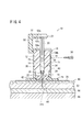
- the stopper that restricts the movement of the movable cylinder 14 is not limited to the stepped portion 40, and for example, as shown in FIG. 6, the small flange 27 may abut against the upper surface of the sealing material 22, The part may be in contact with the upper surface of the support cylinder 12.
- the stopper that limits the progress of the movable cylinder 14 is not limited to a fixed one, and the puncture depth may be adjusted. Further, by providing a convex portion in the outer peripheral direction of the guide groove 36 and the rib 25, the movable cylinder 14 can be locked at a predetermined position.
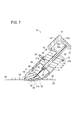
- the flange 24 on the front end surface may be formed at a non-right angle with respect to the axis J direction so that the support cylinder 12 contacts the skin obliquely.
- the syringe 10 according to such a modification can be injected obliquely according to the type and purpose of the procedure.
- the puncture depth can be easily adjusted by puncturing at an angle.
- the syringe according to the present invention is not limited to the above-described embodiment, and various configurations can be adopted without departing from the gist of the present invention.
Landscapes
- Health & Medical Sciences (AREA)
- Vascular Medicine (AREA)
- Engineering & Computer Science (AREA)
- Anesthesiology (AREA)
- Biomedical Technology (AREA)
- Heart & Thoracic Surgery (AREA)
- Hematology (AREA)
- Life Sciences & Earth Sciences (AREA)
- Animal Behavior & Ethology (AREA)
- General Health & Medical Sciences (AREA)
- Public Health (AREA)
- Veterinary Medicine (AREA)
- Infusion, Injection, And Reservoir Apparatuses (AREA)
Abstract
注射器(10)は、一方の端面を皮膚に当接させる支持筒(12)と、支持筒(12)内で皮膚の方向に進行可能な可動筒(14)と、可動筒(14)に連通するように設けられた注射針(16)と、可動筒(14)内で皮膚の方向に進行可能で、該可動筒(14)に充填される薬液(15)を注射針(16)に導出するプランジャ(20)と、支持筒(12)の先端に設けられ、注射針(16)が貫通可能な封止材(22)と、支持筒(12)の先端に備えられたフランジ(24)と、フランジ(24)の皮膚と当接する下面に設けられた粘着剤(26)と、該粘着剤(26)の下側の粘着面に貼られる保護フィルム(28)とを有する。初期状態では、注射針(16)の先端は封止材(22)によって封止されている。
Description
本発明は、薬液を注射する注射器に関し、特に、注射針の穿刺深さを規定することのできる注射器に関する。
人間の皮膚は、表面側から表皮、真皮からなり、皮膚の下に脂肪層等の皮下組織及び筋肉組織があり、皮内注射は表皮又は真皮に注射をし、皮下注射は皮下組織に注射をする。皮内注射及び皮下注射は、薬液の種類や注射の目的に応じて選択される。
表皮及び真皮は比較的薄いことから、所望の皮下又は皮内に注射することは非熟練者にとっては必ずしも簡便ではない。
このような背景から、注射針の皮膚方向への進行を所定のストッパによって制限して、穿刺深さを規定することのできる注射器が提案されている(例えば、特許第2648314号公報又は特表2007-528274号公報参照)。
このような注射器では、注射針の穿刺深さについては規定できて好適であるが、注射をしている最中の注射器は不安定であり、穿刺深さが一定に保たれない懸念がある。
このような注射器では、注射針の穿刺深さについては規定できて好適であるが、注射をしている最中の注射器は不安定であり、穿刺深さが一定に保たれない懸念がある。
また、注射の前に薬液を器具内に充填する必要があり、いわゆるプレフィルド注射器には不向きであり、構造も複雑である。
このような注射器は、プレフィルド式でないことから、適量の薬液を器具内に正確に充填するための手間と注意力が必要であり、しかも注射器とは別の薬液を適切に管理する必要がある。したがって、例えば視力が弱く、又は手先が器用でない患者が自分で薬液を注射することは困難である。
本発明は、構造及び操作が簡便で、プレフィルド式に好適で、しかも注射針の穿刺深さを正確に規定することのできる注射器を提供することを目的とする。
本発明に係る注射器は、一方の端面を皮膚に当接させる支持筒と、前記支持筒内で皮膚の方向に進行可能な可動筒と、前記可動筒に連通するように設けられた後端開口と薬液が吐出する先端開口とを有するルーメンを備える注射針と、前記可動筒内で皮膚の方向に進行可能で、該可動筒に充填された薬液を前記注射針に導出するプランジャと、前記支持筒の先端に設けられ、前記注射針が貫通可能な封止材と、前記可動筒の進行を所定位置で制限するストッパとを有し、初期状態で、前記注射針の先端開口は前記封止材によって封止されていることを特徴とする。
このような注射器は、簡便構造でありながら、支持筒に対して可動筒を押し込む簡便操作により、注射針の穿刺深さが適正長となったところでストッパにより動作制限することができる。また、初期状態では、注射針の先端開口は封止材によって封止することができ、プレフィルド式に好適である。
前記支持筒と前記可動筒は、軸方向に延在するガイドによって相対動作が案内されてもよい。このようなガイドにより、安定した操作が可能になる。
前記支持筒の先端には、前記注射針が挿通する孔を備えるフランジが設けられ、前記封止材は前記フランジに接していてもよい。このようなフランジにより、注射器を安定して皮膚に当接させることができる。
前記フランジには皮膚と当接する面に粘着剤が設けられていてもよい。このような粘着剤によれば、注射器を皮膚に密着させることができ、一層安定した操作が可能で、しかも注射器の穿刺深さが一層正確になる。また、粘着剤により、薬液の漏れが防止でき、正確な量の薬液を注射することができる。
前記フランジは、前記孔の周囲が前記皮膚の方向に向かって膨出していてもよい。フランジにおける孔の周囲が皮膚の方向に向かって膨出していることにより、注射器と皮膚との密着性が向上する。
初期状態で前記可動筒を前記支持筒に固定する第1固手段を有してもよい。第1固定手段により、可動筒が不用意に動作することがなく、注射針の先端が封止材から抜けることを防止できる。
初期状態で前記プランジャを前記可動筒に固定する第2固定手段を有してもよい。第2固定手段により、プランジャが不用意に動作することがなく、内部の薬液が漏れ出すことがない。
前記支持筒は皮膚に対して斜めに当接するように、先端面が軸心方向に対して非直角に形成されていてもよい。これにより、手技の種類や目的に応じて斜めに注射することができる。
以下、本発明に係る注射器について実施の形態を挙げ、添付の図1~図7を参照しながら説明する。以下の説明では、上方及び下方の向きについて図1~図6に示す状態を基準とするが、実際の使用に際しては注射器10の向きは限定されない。
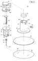
図1、図2及び図3に示すように、本実施の形態に係る注射器10は、一方の端面を皮膚に当接させる支持筒12と、支持筒12内で皮膚の方向に進行可能な可動筒14と、可動筒14に連通するように設けられた注射針16と、可動筒14内で皮膚の方向に進行可能で、該可動筒14に充填される薬液15を注射針16に導出するプランジャ20と、支持筒12の先端に設けられ、注射針16が貫通可能な封止材22と、支持筒12の先端に備えられたフランジ24と、フランジ24の皮膚と当接する下面に設けられた粘着剤26と、該粘着剤26の下側の粘着面に貼られる保護フィルム28とを有する。注射針16は、後端開口31aと薬液が吐出する先端開口31bとを有するルーメン31cを備える。
初期状態(図1参照)では、注射針16の先端開口31bは封止材22によって封止されている。薬液15とはワクチン、ホルモン、鎮静剤等の医薬品や栄養剤を含む広義である。
注射器10は、さらに、初期状態で可動筒14を支持筒12に固定する第1固定具(第1固定手段)30と、初期状態でプランジャ20を可動筒14に固定する第2固定具(第2固定手段)32とを有する。
プランジャ20は、下端に設けられたガスケット18と、上端に設けられた押圧操作用の小フランジ21とを有する。プランジャ20は、一般の注射器で用いられているものである。
可動筒14は、通常の注射器におけるシリンジ本体に相当する部材であり、上端の指掛板19と、周面に等間隔で設けられた軸方向に延在する4本のリブ(ガイド)25と、下端の小フランジ27と、下方に突出する接続部29とを有する。リブ25のうち1本には、第1固定具30が係合する切欠34が設けられている。可動筒14は透明であり、側面に目盛りが設けられている。接続部29には、注射針16のハブ35が接着・溶着・嵌合等によって固定されている。注射針16は、中空のテーパ針であり、インスリン注射器で用いられているものである。
支持筒12は透明で、内腔部で可動筒14をスライド可能に支持する構成であり、リブ25が係合する軸方向に延在する4本のガイド溝36と、側面に設けられ第1固定具30が挿入される固定孔38とを有する。ガイド溝36は、内腔部における上端から途中部分まで延在しており、リブ25とともに支持筒12と可動筒14とを軸方向に安定して相対動作するように作用する。ガイド溝36の下端の段差部(ストッパ)40は、可動筒14の進行を所定位置で制限するストッパとして作用する。段差部40は、リブ25が当接したときに注射針16の粘着剤26からの突出量が、規定長さとなるように設定されている。この規定長さは、皮下注射用、皮内注射用等の手技の種類や、薬液15の量や種別や、その他の要件に応じて設定されている。
支持筒12の内腔部下端には円柱形の封止材22が固定されて、初期状態で注射針16の先端が略中央部まで穿刺されており、該注射針16を封止している。封止材22は、例えばゴム体(シリコーンゴムやブチルゴム等)である。
支持筒12のさらに先端には、フランジ24が一体的に固定されている。フランジ24は支持筒12よりも大径(例えば略2倍の径)であり、中央部に設けられた注射針16が挿通する小さい孔42と、該孔42の周囲が皮膚の方向に向かってわずかに膨出した膨出部44とを有する。孔42の周囲の膨出部44が皮膚の方向に向かって膨出していることにより、注射器10と皮膚との密着性が向上する。フランジ24と封止材22は隙間なく接している。このようなフランジ24により、注射器10を安定して皮膚に当接させることができる。
膨出部の曲率半径は特に限定されないが、例えば6mm~200mm、好ましくは10mm~100mm、より好ましくは20mm~60mmにするとよい。
粘着剤26は、注射針16が貫通可能な薄く柔らかい材質で、フランジ24よりも大径(例えば略2倍の径)であり、該フランジ24に固定されている。粘着剤26としては、ゴム系、アクリル系、シリコーン系などの粘着剤が使用される。感圧性ホットメルトタイプ、架橋タイプなどがある。形状についは、円、楕円、星形など穿刺部位が理解しやすい形状にするよい。粘着剤26の下面は、粘着面となっており、初期状態では保護フィルム28が貼られていて、粘着性が保持されている。保護フィルム28は、粘着剤26から剥がしやすいように、小さいピールタブ46が膨出している。
第1固定具30はピン形状であり、初期状態で固定孔38を介して可動筒14の切欠39に係合する。これにより、可動筒14が不用意に動作することがなく、注射針16の先端が封止材22から抜けることを防止できる。第1固定具30は独立した部品である必要はなく、例えば支持筒12と可動筒14とを一部で固定した固定部として、使用時に切り離し可能な構成にしてもよい。第2固定具32についても同様である。
第2固定具32は、軸方向のロッド50と、該ロッド50の上端部で小フランジ21を上面及び下面で挟持する挟持板52a及び52bと、ロッド50の下端で指掛板19を上面及び下面で挟持する挟持板54a及び54bとを有する。挟持板52b、54a及び54bは、プランジャ20及び可動筒14の本体部との干渉避けるための切欠きが設けられており、略U字形状となっている。このような第2固定具32は、初期状態でプランジャ20を可動筒14に固定しておくことができ、プランジャ20が不用意に動作することがなく、内部の薬液15が漏れ出すことがない。
注射器10は、注射を実施する際の初期状態で図1に示すように組み立てられており、可動筒14の内部には規定量の薬液15が予め充填された、いわゆるプレフィルド式である。薬液15は、封止材22とガスケット18によって封止されている。初期状態では、第1固定具30及び第2固定具32が所定位置に装着されており、支持筒12と可動筒14との相対動作、及び可動筒14とプランジャ20との相対動作を防止している。
図1~図3から明らかなように、注射器10は簡便構造である。注射器10は予め滅菌され、あるいは実質的に無菌状態で作製されて、該滅菌状態あるいは無菌状態が維持されるように包装されており、使用後には所定の方法で廃棄される、いわゆるディスポーザブル品である。
次に、このように構成される注射器10の作用について説明する。
先ず、ピールタブ46を持って保護フィルム28を粘着剤26から剥がし、皮膚の所定箇所に貼り付ける。注射器10は、粘着剤26の粘着作用と、広い面積のフランジ24によって安定し、皮膚に密着して固定される。また、フランジ24の膨出部44の作用により、穿刺箇所を適度に圧迫して密着性が向上する。これにより、注射針16が皮膚に当たったときに、皮膚が逃げることがなく、針先が皮膚内に速やかに進入する。
次いで、図4に示すように、第1固定具30を取り除いた後、リブ25が段差部40に当接するまで可動筒14を押し下げる。これにより、注射針16は、封止材22を貫通し、孔42を通り、粘着剤26を貫通して皮膚に穿刺される。例えば、皮内注射をする場合には、注射針16の先端は、さらに皮膚の表皮60を通って、真皮62に達するが、皮下組織64までは達することがなく、穿刺深さが適正長となったところで停止する。注射針16は、封止材22によって適度に圧迫されており、摩擦力を受けて安定している。
皮下注射をする場合には、注射針16の先端は表皮60及び真皮62を通って脂肪層64に達するが、筋肉組織66までは達することがなく、穿刺深さが適正長となったところで停止する。
また、この時点では第2固定具32は装着されたままであることから、プランジャ20は可動筒14に対して相対的に動作をすることがなく、内部の薬液15が表皮60、真皮62等に漏出することがない。
さらに、図5に示すように、第2固定具32を取り除いた後、ガスケット18が可動筒14の下面に当接するまでプランジャ20を押し下げる。これにより、薬液15は、注射針16に導出されて、生体内に注入される。ここで、注射器10はフランジ24及び粘着剤26の作用により安定し、注射針16の穿刺深さは適正に保持されていることから、所望の深さに規定量の薬液15を注入することができる。また、粘着剤26が漏れ止めとなり、薬液15を正確に注入できる。
特に、皮内注射の場合には、注射針16の先端は表皮60又は真皮62の深さまでしか達しないので皮膚の表面までの距離が短いが、粘着剤26が皮膚に密着して覆っているので漏れ止めの作用を奏し、薬液15が皮膚表面に漏れ出ることがなく、規定量の薬液15を正確に注射することができる。
注射をする際には、可動筒14の目盛りを見ながら速度を調整するとよい。注射器10では、基本的には内部の薬液15を全て生体に注入するが、条件によっては目盛りを見ながら適量だけ注入するようにしてもよい。
この後、注射器10を皮膚から取り外して一連の注射の手技を終了する。
上述したように、本実施の形態に係る注射器10は、簡便な構造でありながら、支持筒12に対して可動筒14を押し込む簡便操作により、注射針16の穿刺深さが適正長となったところで段差部40により動作制限することができる。また、初期状態では、注射針16の先端開口31bは封止材22によって封止することができ、プレフィルド式に好適である。注射器10は、プレフィルド式であり、簡便な操作で適量の薬液を器具内に正確に注入することができ、例えば視力が弱く、又は手先が器用でない患者が自分で薬液を注射することもできる。
可動筒14の進行を制限するストッパは段差部40に限らず、例えば図6に示すように小フランジ27が封止材22の上面に当接するようにしてもよいし、指掛板19の一部が支持筒12の上面に当接するようにしてもよい。可動筒14の進行を制限するストッパは、固定的なものに限らず、穿刺深さを調整できるようにしてもよい。また、ガイド溝36とリブ25の外周方向に凸形状部を設けることにより、可動筒14を所定位置に係止することができる。
図7に示すように、支持筒12は皮膚に対して斜めに当接するように、先端面のフランジ24が軸心J方向に対して非直角に形成されていてもよい。このような変形例に係る注射器10では手技の種類や目的に応じて斜めに注射することができる。斜めに穿刺をすることにより、穿刺深さの調整が容易になる。
本発明に係る注射器は、上述の実施の形態に限らず、本発明の要旨を逸脱することなく、種々の構成を採り得ることはもちろんである。
Claims (8)
- 一方の端面を皮膚に当接させる支持筒(12)と、
前記支持筒(12)内で皮膚の方向に進行可能な可動筒(14)と、
前記可動筒(14)に連通するように設けられた後端開口と薬液(15)が吐出する先端開口(31b)とを有するルーメン(31c)を備える注射針(16)と、
前記可動筒(14)内で皮膚の方向に進行可能で、該可動筒(14)に充填された薬液(15)を前記注射針(16)に導出するプランジャ(20)と、
前記支持筒(12)の先端に設けられ、前記注射針(16)が貫通可能な封止材(22)と、
前記可動筒(14)の進行を所定位置で制限するストッパ(40)と、
を有し、
初期状態で、前記注射針(16)の先端開口は前記封止材(22)によって封止されていることを特徴とする注射器。 - 請求項1記載の注射器において、
前記支持筒(12)と前記可動筒(14)は、軸方向に延在するガイド(25)によって相対動作が案内されることを特徴とする注射器。 - 請求項1又は2記載の注射器において、
前記支持筒(12)の先端には、前記注射針(16)が挿通する孔を備えるフランジ(24)が設けられ、前記封止材(22)は前記フランジ(24)に接していることを特徴とする注射器。 - 請求項3記載の注射器において、
前記フランジ(24)には皮膚と当接する面に粘着剤が設けられていることを特徴とする注射器。 - 請求項3又は4記載の注射器において、
前記フランジ(24)は、前記孔の周囲が前記皮膚の方向に向かって膨出していることを特徴とする注射器。 - 請求項1~5のいずれか1項に記載の注射器において、
初期状態で前記可動筒(14)を前記支持筒(12)に固定する第1固手段(30)を有することを特徴とする注射器。 - 請求項1~6のいずれか1項に記載の注射器において、
初期状態で前記プランジャ(20)を前記可動筒(14)に固定する第2固定手段(32)を有することを特徴とする注射器。 - 請求項1~7のいずれか1項に記載の注射器において、
前記支持筒(12)は皮膚に対して斜めに当接するように、先端面が軸心方向に対して非直角に形成されていることを特徴とする注射器。
Priority Applications (2)
| Application Number | Priority Date | Filing Date | Title |
|---|---|---|---|
| JP2010505817A JP5385260B2 (ja) | 2008-03-28 | 2009-03-27 | 注射器 |
| US12/892,612 US9044556B2 (en) | 2008-03-28 | 2010-09-28 | Injector |
Applications Claiming Priority (2)
| Application Number | Priority Date | Filing Date | Title |
|---|---|---|---|
| JP2008086695 | 2008-03-28 | ||
| JP2008-086695 | 2008-03-28 |
Related Child Applications (1)
| Application Number | Title | Priority Date | Filing Date |
|---|---|---|---|
| US12/892,612 Continuation US9044556B2 (en) | 2008-03-28 | 2010-09-28 | Injector |
Publications (1)
| Publication Number | Publication Date |
|---|---|
| WO2009119787A1 true WO2009119787A1 (ja) | 2009-10-01 |
Family
ID=41113971
Family Applications (1)
| Application Number | Title | Priority Date | Filing Date |
|---|---|---|---|
| PCT/JP2009/056225 Ceased WO2009119787A1 (ja) | 2008-03-28 | 2009-03-27 | 注射器 |
Country Status (3)
| Country | Link |
|---|---|
| US (1) | US9044556B2 (ja) |
| JP (1) | JP5385260B2 (ja) |
| WO (1) | WO2009119787A1 (ja) |
Cited By (10)
| Publication number | Priority date | Publication date | Assignee | Title |
|---|---|---|---|---|
| JP2011516205A (ja) * | 2008-04-10 | 2011-05-26 | ヘンリー フォード ヘルス システム | 心筋組織への注入深度の制御の装置および方法 |
| JP2013526364A (ja) * | 2010-05-17 | 2013-06-24 | ベクトン・ディキンソン・アンド・カンパニー | 針注入深さ調整付き針組立体 |
| JP2015501676A (ja) * | 2011-11-16 | 2015-01-19 | エルテーエス ローマン テラピー−ジステーメ アーゲー | 短いカニューレを備えたバレル−プランジャ・ユニット |
| JP2015126891A (ja) * | 2015-02-23 | 2015-07-09 | ベクトン・ディキンソン・アンド・カンパニーBecton, Dickinson And Company | 針注入深さ調整付き針組立体 |
| WO2017170502A1 (ja) * | 2016-03-30 | 2017-10-05 | テルモ株式会社 | 注射器 |
| JP2020199385A (ja) * | 2015-01-30 | 2020-12-17 | ベクトン・ディキンソン・アンド・カンパニーBecton, Dickinson And Company | 患者接触表面を備えたペンニードルハブ |
| JP2021529579A (ja) * | 2018-07-10 | 2021-11-04 | アルコン インコーポレイティド | 眼内レンズインジェクタ |
| JP2022552487A (ja) * | 2019-10-11 | 2022-12-16 | ジャイロスコープ・セラピューティクス・リミテッド | シリンジのための投薬クリップ組立体 |
| JP2023043086A (ja) * | 2021-09-15 | 2023-03-28 | 学校法人慈恵大学 | 生体組織処理装置 |
| WO2025197571A1 (ja) * | 2024-03-19 | 2025-09-25 | テルモ株式会社 | 医療デバイス |
Families Citing this family (16)
| Publication number | Priority date | Publication date | Assignee | Title |
|---|---|---|---|---|
| US12097357B2 (en) | 2008-09-15 | 2024-09-24 | West Pharma. Services IL, Ltd. | Stabilized pen injector |
| US9427529B2 (en) | 2008-09-15 | 2016-08-30 | Medimop Medical Projects Ltd. | Safeguard mechanism for autoinjector needle |
| US9393369B2 (en) | 2008-09-15 | 2016-07-19 | Medimop Medical Projects Ltd. | Stabilized pen injector |
| US9199044B2 (en) * | 2012-08-06 | 2015-12-01 | Elwha Llc | Devices and methods for wearable injection guides |
| CN104602741B (zh) | 2013-03-26 | 2018-10-26 | 泰尔茂株式会社 | 弹性帽以及具备所述弹性帽的注射器用组装体 |
| ES2728054T3 (es) * | 2013-06-18 | 2019-10-22 | Enable Injections Inc | Aparato de transferencia e inyección de viales |
| EP4442299A3 (en) * | 2013-09-30 | 2025-08-13 | Medimop Medical Projects Ltd | Stabilized pen injector |
| CN208031609U (zh) | 2013-12-04 | 2018-11-02 | 贝克顿·迪金森公司 | 笔式针 |
| US11577030B2 (en) | 2013-12-04 | 2023-02-14 | Embecta Corp. | Pen needle attachment mechanisms |
| WO2015153899A1 (en) * | 2014-04-02 | 2015-10-08 | Zogenix, Inc. | Kits for drug delivery site preparation |
| EP3978047B1 (en) | 2016-08-01 | 2023-08-23 | West Pharma Services IL, Ltd | Partial door closure prevention spring |
| EP3538185B1 (en) | 2016-11-04 | 2025-10-08 | Takeda Pharmaceutical Company Limited | Small unit dosage plunger rod stops |
| EP3630226B1 (en) | 2017-05-30 | 2025-10-22 | West Pharma. Services Il, Ltd. | Modular drive train for wearable injector |
| WO2020023336A1 (en) * | 2018-07-24 | 2020-01-30 | Amgen Inc. | Hybrid drug delivery devices with grip portion |
| KR102007125B1 (ko) * | 2018-07-30 | 2019-08-02 | 이민우 | 다수의 소형 주사기 또는 주사부를 갖는 주사용 패드 |
| JP7771348B2 (ja) * | 2021-07-14 | 2025-11-17 | エスエイチエル・メディカル・アーゲー | 注射支持パッド |
Citations (4)
| Publication number | Priority date | Publication date | Assignee | Title |
|---|---|---|---|---|
| US6045534A (en) * | 1997-10-27 | 2000-04-04 | Sarcos, Inc. | Disposable fluid injection module |
| JP2000506025A (ja) * | 1996-02-12 | 2000-05-23 | ローヌ・プランク ローラー アルツナイミッテル ゲゼルシャフト ミット ベシュレンクテル ハフツング | 区切られた量で液体を出すための装置 |
| WO2007027203A2 (en) * | 2005-04-11 | 2007-03-08 | Becton, Dickinson And Company | Injection device with secondary reservoir |
| JP2007111537A (ja) * | 2005-10-19 | 2007-05-10 | Animas Corp | 安全注入セット |
Family Cites Families (2)
| Publication number | Priority date | Publication date | Assignee | Title |
|---|---|---|---|---|
| US4886499A (en) | 1986-12-18 | 1989-12-12 | Hoffmann-La Roche Inc. | Portable injection appliance |
| US7108679B2 (en) | 2004-03-11 | 2006-09-19 | Becton, Dickinson And Company | Intradermal syringe and needle assembly |
-
2009
- 2009-03-27 WO PCT/JP2009/056225 patent/WO2009119787A1/ja not_active Ceased
- 2009-03-27 JP JP2010505817A patent/JP5385260B2/ja not_active Expired - Fee Related
-
2010
- 2010-09-28 US US12/892,612 patent/US9044556B2/en not_active Expired - Fee Related
Patent Citations (4)
| Publication number | Priority date | Publication date | Assignee | Title |
|---|---|---|---|---|
| JP2000506025A (ja) * | 1996-02-12 | 2000-05-23 | ローヌ・プランク ローラー アルツナイミッテル ゲゼルシャフト ミット ベシュレンクテル ハフツング | 区切られた量で液体を出すための装置 |
| US6045534A (en) * | 1997-10-27 | 2000-04-04 | Sarcos, Inc. | Disposable fluid injection module |
| WO2007027203A2 (en) * | 2005-04-11 | 2007-03-08 | Becton, Dickinson And Company | Injection device with secondary reservoir |
| JP2007111537A (ja) * | 2005-10-19 | 2007-05-10 | Animas Corp | 安全注入セット |
Cited By (19)
| Publication number | Priority date | Publication date | Assignee | Title |
|---|---|---|---|---|
| US8801665B2 (en) | 2008-04-10 | 2014-08-12 | Henry Ford Health System | Apparatus and method for controlled depth of injection into myocardial tissue |
| JP2011516205A (ja) * | 2008-04-10 | 2011-05-26 | ヘンリー フォード ヘルス システム | 心筋組織への注入深度の制御の装置および方法 |
| JP2013526364A (ja) * | 2010-05-17 | 2013-06-24 | ベクトン・ディキンソン・アンド・カンパニー | 針注入深さ調整付き針組立体 |
| JP2015501676A (ja) * | 2011-11-16 | 2015-01-19 | エルテーエス ローマン テラピー−ジステーメ アーゲー | 短いカニューレを備えたバレル−プランジャ・ユニット |
| JP7183231B2 (ja) | 2015-01-30 | 2022-12-05 | エンベクタ コーポレイション | 患者接触表面を備えたペンニードルハブ |
| JP2020199385A (ja) * | 2015-01-30 | 2020-12-17 | ベクトン・ディキンソン・アンド・カンパニーBecton, Dickinson And Company | 患者接触表面を備えたペンニードルハブ |
| JP2015126891A (ja) * | 2015-02-23 | 2015-07-09 | ベクトン・ディキンソン・アンド・カンパニーBecton, Dickinson And Company | 針注入深さ調整付き針組立体 |
| WO2017170502A1 (ja) * | 2016-03-30 | 2017-10-05 | テルモ株式会社 | 注射器 |
| JPWO2017170502A1 (ja) * | 2016-03-30 | 2019-02-07 | テルモ株式会社 | 注射器 |
| JP2021529579A (ja) * | 2018-07-10 | 2021-11-04 | アルコン インコーポレイティド | 眼内レンズインジェクタ |
| JP7326354B2 (ja) | 2018-07-10 | 2023-08-15 | アルコン インコーポレイティド | 眼内レンズインジェクタ |
| JP2023133462A (ja) * | 2018-07-10 | 2023-09-22 | アルコン インコーポレイティド | 眼内レンズインジェクタ |
| JP7512490B2 (ja) | 2018-07-10 | 2024-07-08 | アルコン インコーポレイティド | 眼内レンズインジェクタ |
| US12329633B2 (en) | 2018-07-10 | 2025-06-17 | Alcon Inc. | Intraocular lens injector |
| JP2022552487A (ja) * | 2019-10-11 | 2022-12-16 | ジャイロスコープ・セラピューティクス・リミテッド | シリンジのための投薬クリップ組立体 |
| JP7455962B2 (ja) | 2019-10-11 | 2024-03-26 | ジャイロスコープ・セラピューティクス・リミテッド | シリンジのための投薬クリップ組立体 |
| JP2023043086A (ja) * | 2021-09-15 | 2023-03-28 | 学校法人慈恵大学 | 生体組織処理装置 |
| JP7778344B2 (ja) | 2021-09-15 | 2025-12-02 | 学校法人慈恵大学 | 生体組織処理装置 |
| WO2025197571A1 (ja) * | 2024-03-19 | 2025-09-25 | テルモ株式会社 | 医療デバイス |
Also Published As
| Publication number | Publication date |
|---|---|
| US20110040280A1 (en) | 2011-02-17 |
| JP5385260B2 (ja) | 2014-01-08 |
| US9044556B2 (en) | 2015-06-02 |
| JPWO2009119787A1 (ja) | 2011-07-28 |
Similar Documents
| Publication | Publication Date | Title |
|---|---|---|
| JP5385260B2 (ja) | 注射器 | |
| US7988667B2 (en) | Piercing tool | |
| JP6284595B2 (ja) | 注射針組立体及び薬剤注射装置 | |
| JP5244794B2 (ja) | 留置針組立体の製造方法 | |
| EP2531242B1 (en) | Dermal access device | |
| US8246578B2 (en) | Puncture device | |
| EP3275490A1 (en) | Injection needle assembly, and drug injection device | |
| CN101340940B (zh) | 用于药物射流喷射单元的皮肤保持装置 | |
| KR20150005605A (ko) | 수조작 압력 작동식 적용 메커니즘 | |
| CN102369034A (zh) | 注射针组合体及药剂注射装置 | |
| US20140170594A1 (en) | Dual medicament carpule for dental syringes | |
| WO2011040219A1 (ja) | 注射針組立体および薬剤注射装置 | |
| WO2016072060A1 (ja) | マイクロニードルセット | |
| JP5118533B2 (ja) | 注射針セット | |
| JPWO2017073658A1 (ja) | グリップ及び注射器組立体 | |
| JP2025129396A (ja) | マイクロニードルアレイ穿刺用デバイス | |
| JP2011212183A (ja) | プレフィルドシリンジ | |
| US8734390B2 (en) | Injection aid and medication syringe device | |
| CN110478576A (zh) | 一种固定穿刺角度及深度的皮内注射针组件 | |
| JP2002272853A (ja) | 留置針セット | |
| KR20240128477A (ko) | 개량형 카테터 | |
| JP2024044241A (ja) | 医療用穿刺針及び針保護部材 | |
| WO2005011800A1 (en) | Intravenous cannula system | |
| KR20180130820A (ko) | 안전주사기 |
Legal Events
| Date | Code | Title | Description |
|---|---|---|---|
| 121 | Ep: the epo has been informed by wipo that ep was designated in this application |
Ref document number: 09723895 Country of ref document: EP Kind code of ref document: A1 |
|
| ENP | Entry into the national phase |
Ref document number: 2010505817 Country of ref document: JP Kind code of ref document: A |
|
| NENP | Non-entry into the national phase |
Ref country code: DE |
|
| 122 | Ep: pct application non-entry in european phase |
Ref document number: 09723895 Country of ref document: EP Kind code of ref document: A1 |