WO2009113489A1 - Silver-white copper alloy and process for producing the same - Google Patents
Silver-white copper alloy and process for producing the same Download PDFInfo
- Publication number
- WO2009113489A1 WO2009113489A1 PCT/JP2009/054420 JP2009054420W WO2009113489A1 WO 2009113489 A1 WO2009113489 A1 WO 2009113489A1 JP 2009054420 W JP2009054420 W JP 2009054420W WO 2009113489 A1 WO2009113489 A1 WO 2009113489A1
- Authority
- WO
- WIPO (PCT)
- Prior art keywords
- mass
- phase
- heat treatment
- cold
- content
- Prior art date
Links
Images


Classifications
-
- C—CHEMISTRY; METALLURGY
- C22—METALLURGY; FERROUS OR NON-FERROUS ALLOYS; TREATMENT OF ALLOYS OR NON-FERROUS METALS
- C22C—ALLOYS
- C22C9/00—Alloys based on copper
- C22C9/04—Alloys based on copper with zinc as the next major constituent
-
- B—PERFORMING OPERATIONS; TRANSPORTING
- B22—CASTING; POWDER METALLURGY
- B22D—CASTING OF METALS; CASTING OF OTHER SUBSTANCES BY THE SAME PROCESSES OR DEVICES
- B22D11/00—Continuous casting of metals, i.e. casting in indefinite lengths
- B22D11/001—Continuous casting of metals, i.e. casting in indefinite lengths of specific alloys
- B22D11/004—Copper alloys
-
- C—CHEMISTRY; METALLURGY
- C22—METALLURGY; FERROUS OR NON-FERROUS ALLOYS; TREATMENT OF ALLOYS OR NON-FERROUS METALS
- C22C—ALLOYS
- C22C30/00—Alloys containing less than 50% by weight of each constituent
- C22C30/02—Alloys containing less than 50% by weight of each constituent containing copper
-
- C—CHEMISTRY; METALLURGY
- C22—METALLURGY; FERROUS OR NON-FERROUS ALLOYS; TREATMENT OF ALLOYS OR NON-FERROUS METALS
- C22C—ALLOYS
- C22C30/00—Alloys containing less than 50% by weight of each constituent
- C22C30/04—Alloys containing less than 50% by weight of each constituent containing tin or lead
-
- C—CHEMISTRY; METALLURGY
- C22—METALLURGY; FERROUS OR NON-FERROUS ALLOYS; TREATMENT OF ALLOYS OR NON-FERROUS METALS
- C22C—ALLOYS
- C22C30/00—Alloys containing less than 50% by weight of each constituent
- C22C30/06—Alloys containing less than 50% by weight of each constituent containing zinc
-
- C—CHEMISTRY; METALLURGY
- C22—METALLURGY; FERROUS OR NON-FERROUS ALLOYS; TREATMENT OF ALLOYS OR NON-FERROUS METALS
- C22F—CHANGING THE PHYSICAL STRUCTURE OF NON-FERROUS METALS AND NON-FERROUS ALLOYS
- C22F1/00—Changing the physical structure of non-ferrous metals or alloys by heat treatment or by hot or cold working
- C22F1/08—Changing the physical structure of non-ferrous metals or alloys by heat treatment or by hot or cold working of copper or alloys based thereon
Definitions
- the present invention relates to a copper alloy exhibiting a silver white color equivalent to that of white and a method for producing the same.
- Copper alloys such as brass are used in various applications such as plumbing equipment, building materials, electrical / electronic equipment, machine parts, etc.
- a white (silver white) color tone may be required, and conventionally, a copper alloy product is subjected to a plating treatment such as nickel / chrome plating in order to cope with such a demand.
- the plating product has a problem that the plating layer on the surface peels off after long-term use, and when the plating product is re-dissolved, the plating material is mixed in the copper alloy and deteriorates the quality. There was also a problem. Therefore, a Cu—Ni—Zn alloy which itself exhibits a glossy white color has been proposed.
- JIS C7941 includes Cu (60.0 to 64.0 mass%), Ni (16.5 to 19.5 mass%), Pb (0.8 to 1.8 mass%), Zn Free-cutting whites containing (remainder) etc. are prescribed.
- Japanese Patent No. 2828418 discloses Cu (41.0 to 44.0 mass%), Ni (10.1 to 14.0 mass%), Pb (0.5 to 3.0 mass%).
- Zn (remainder) containing white copper alloy is disclosed.
- these copper alloys contain a large amount of Ni and Pb, have problems in health and hygiene, and their use is limited. That is, Ni causes a particularly strong Ni allergy among metal allergies, and Pb is a harmful substance as is well known, and therefore has a problem in use as a key or the like that directly touches human skin. In addition, due to reasons such as containing a large amount of Ni, it is inferior in workability such as hot rollability, machinability, pressability, etc., and in combination with the fact that Ni is expensive, the manufacturing cost becomes high, and this surface But its use is limited.
- the present invention provides a silver-white copper alloy that exhibits a silver-white color equivalent to that of Western white without causing such problems, and that is excellent in hot workability and the like, and that can be suitably manufactured. It aims at providing the manufacturing method of a copper alloy.
- the present invention proposes the following silver-white copper alloy and its manufacturing method in order to solve the above-mentioned problems.
- Cu 47.5 to 50.5 mass% (preferably 47.9 to 49.9 mass%) and Ni: 7.8 to 9.8 mass% (preferably 8.2). 9.6 mass%, more preferably 8.4 to 9.5 mass%) and Mn: 4.7 to 6.3 mass% (preferably 5.0 to 6.2 mass%, more preferably 5.2 to 6).
- a silver-white copper alloy characterized by having a metal structure in which a ⁇ phase of 2 to 17% in area ratio is dispersed in an ⁇ phase matrix. "Copper alloy”).
- the second aspect of the present invention is a copper alloy further containing one or more elements selected from Pb, Bi, C, and S in addition to the constituent elements of the first copper alloy, wherein Cu: 47. 5 to 50.5 mass% (preferably 47.9 to 49.9 mass%) and Ni: 7.8 to 9.8 mass% (preferably 8.2 to 9.6 mass%, more preferably 8.4 to 9) 0.5 mass%), Mn: 4.7 to 6.3 mass% (preferably 5.0 to 6.2 mass%, more preferably 5.2 to 6.2 mass%), and Pb: 0.001 to 0.00 mass.
- Second copper alloy characterized by forming a metal structure in which a ⁇ phase of 2 to 17% by weight is dispersed
- the present invention thirdly relates to a copper alloy further containing one or more elements selected from Al, P, Zr, and Mg in addition to the constituent elements of the first copper alloy. 5 to 50.5 mass% (preferably 47.9 to 49.9 mass%) and Ni: 7.8 to 9.8 mass% (preferably 8.2 to 9.6 mass%, more preferably 8.4 to 9) 0.5 mass%), Mn: 4.7 to 6.3 mass% (preferably 5.0 to 6.2 mass%, more preferably 5.2 to 6.2 mass%), and Al: 0.01 to 0.3 mass%.
- a silver-white copper alloy (hereinafter referred to as “third copper alloy”) which has a metal structure in which 2 to 17% of ⁇ phase is dispersed.
- the present invention fourthly relates to a copper alloy further containing one or more elements selected from Al, P, Zr, and Mg in addition to the constituent elements of the second copper alloy, wherein Cu: 47. 5 to 50.5 mass% (preferably 47.9 to 49.9 mass%) and Ni: 7.8 to 9.8 mass% (preferably 8.2 to 9.6 mass%, more preferably 8.4 to 9) 0.5 mass%), Mn: 4.7 to 6.3 mass% (preferably 5.0 to 6.2 mass%, more preferably 5.2 to 6.2 mass%), and Pb: 0.001 to 0.00 mass.
- the alloy composition is composed of one or more selected elements and Zn: the balance, and the above relations f1, f2, and f3 are established among the contents of Cu, Ni, and Mn.
- a silver-white copper alloy (hereinafter referred to as “fourth copper alloy”) characterized by forming a metal structure in which a ⁇ phase of 2 to 17% in terms of area ratio is dispersed is proposed.
- [a] indicates a dimensionless value of the content of the element a
- the content of the element a is represented by [a] mass%.
- the Cu content is [Cu] mass%.
- the content of the ⁇ phase depends on the area ratio, and the dimensionless value of the content is indicated by [ ⁇ ]. That is, the ⁇ -phase content (area ratio or area content) is expressed in [ ⁇ ]%.
- the area ratio which is the content of ⁇ phase, is measured by image analysis. Specifically, for hot-worked materials and castings, an optical micrograph of 100 times the final product (hot-worked product).
- Continuous casting is obtained by binarizing a 200- or 500-fold optical microstructure, mainly a metal structure analyzed by FE-SEM-EBSP, using image processing software "WinROOF” (Techjam Corporation). It is an average value of the area ratio measured at two predetermined locations and three fields of view.
- the copper alloy is subjected to at least one heat treatment and cold working (rolling) on a hot working material obtained by hot working (rolling, extruding). Processing, drawing)), or as a continuous casting that is obtained by subjecting a casting material (continuous casting material) obtained by continuous casting to one or more heat treatments and cold working,
- a casting material continuous casting material obtained by continuous casting to one or more heat treatments and cold working
- it is suitably used as a constituent material of a key, a key blank or a pressed product.
- the average crystal grain size of the ⁇ phase is 0.003 to 0.018 mm
- the average area of the ⁇ phase (hereinafter referred to as “ ⁇ phase area”) is 4 ⁇ 10 ⁇ . It is preferably 6 to 80 ⁇ 10 ⁇ 6 mm 2 and the average value of the long side / short side of the ⁇ phase (hereinafter referred to as “long side / short side ratio”) is 2 to 7.
- the average area of ⁇ phase ( ⁇ phase area) is a value obtained by dividing the total area of ⁇ phases in a specific cross section of the copper alloy by the number of ⁇ phases.
- the average value of ⁇ phase is obtained for each specific cross section, and the average value (the sum of the average values of ⁇ phases of all specific cross sections is the number of specific cross sections) (The value divided by) is the average area of the ⁇ phase.
- the specific cross section is parallel to the length direction (rolling direction) of the plate-like material and the surface (or the back surface) of the plate-like material.
- the cross section is orthogonal to For example, the two specific cross sections are cross sections at positions t / 3 and t / 6 (t is a plate thickness) from the surface of the plate-like object.
- a cross section parallel to the axis of the cylindrical object is defined as a specific cross section.
- the two specific cross sections are parallel cross sections at positions of d / 3 and d / 6 (d is a diameter of a circular cross section perpendicular to the axis of the cylindrical object).
- the long side of the ⁇ phase is a direction parallel to the longitudinal direction (in the case of a plate-like product, in the length direction (rolling direction), and in the case of a cylindrical product, the axial direction (extrusion direction, drawing).
- the short side of the ⁇ phase is the length in the direction perpendicular to the long side in the specific cross section.
- the average value of the long side / short side of the ⁇ phase is an average value of the values of the long side / short side of each ⁇ phase obtained in each specific cross section.
- the ratio of the ⁇ phase having a long side / short side value of 12 or less to the total ⁇ phase (hereinafter referred to as “12 or less ⁇ phase ratio”) is 95% or more, or long It is preferable that the number of ⁇ phases having sides of 0.06 mm or more is within 10 per 0.1 mm 2 .
- the length of the ⁇ phase (long side, short side) is the final product when the specific cross section is observed with a hot-processed material, and with a metal structure with a 100 ⁇ optical microscope for castings (with a field of view of 50 ⁇ 100 mm). (Hot-worked products, continuous castings) are observed and measured with an optical microscope structure of 200 times or 500 times, mainly a metal structure analyzed by FE-SEM-EBSP.
- the content (area ratio) of the ⁇ phase in the hot-working material or continuous casting material is preferably 12 to 40%.
- the content (area ratio) of the ⁇ phase in the heat-treated material (primary heat-treated material) ) Is 3 to 24%
- the average value of the long side / short side of the ⁇ phase is 2 to 18
- the ratio of the ⁇ phase having the long side / short side value of 20 or more to the total ⁇ phase is 30% It is preferable that the number of ⁇ phases having a long side of 0.5 mm or more is within 10 per 1 mm 2 of the specific cross section.
- Fe and / or Si may be contained as unavoidable impurities.
- the Fe content is preferably 0.3 mass% or less
- the Si content is preferably 0.1 mass% or less.
- Co is also contained in Ni if it is a small amount in JIS or the like, for example, if the Co content is about 0.1%, it is treated as an inevitable impurity.
- the present invention fourthly proposes a method for producing the first to fourth copper alloys described above. That is, in the present invention, one or more heat treatments (heating temperature: 550 to 760 ° C., heating time: 2 to 2) are applied to a hot working material obtained by hot working (hot rolling, hot extrusion, etc.) of an ingot.
- one or more heat treatments heat temperature: 550 to 760 ° C., heating time: 2 to 2
- a hot working material obtained by hot working (hot rolling, hot extrusion, etc.) of an ingot.
- roller manufacturing method 36 hours, average cooling rate up to 500 ° C .: 1 ° C./min or less) and cold working to obtain a hot-worked product that is the copper alloy Method (hereinafter referred to as “rolling manufacturing method”) and one or more heat treatments (casting temperature: 550 to 760 ° C., heating time: 2 to 36 hours, average cooling rate up to 500 ° C.) for the cast material obtained by continuous casting 1 ° C./min or less) and a cold-working process to obtain a continuous cast casting that is the copper alloy (hereinafter referred to as “casting manufacturing method”). Propose.
- the first heat treatment applied to the hot-worked material or continuous casting material is performed under the conditions of heating temperature: 600 to 760 ° C. and heating time: 2 to 36 hours.
- a heating step and a cooling step of slow cooling to at least 500 ° C. at an average cooling rate of 1 ° C./min or less, and the processing rate in the first cold working applied to the primary heat treatment material subjected to the heat treatment is It is preferably 25% or more.
- this cooling step it is also preferable that the temperature is gradually cooled to 500 to 550 ° C. at an average cooling rate of 1 ° C./min or less and then maintained at that temperature for 1 to 2 hours.
- the ⁇ phase generated in the raw material production stage is reduced to a predetermined size and shape.
- the material hot work material, casting material
- the material may be subjected to light cold work with a working rate of less than 25%. It is not the first cold working in the manufacturing method or casting method.
- this heat treatment is treated as the first heat treatment.
- the heating process in the second and subsequent heat treatments is performed by heating temperature: 550 to 625 ° C., heating time: 2 to 2 It is preferable to carry out under conditions of 36 hours. It should be noted that the processing rate of cold working performed after the final heat treatment is 50% or less.
- Cu is a main element that is fundamental in determining all the characteristics of the copper alloy, and also has a balance with other contained elements Zn, Ni, Mn.
- the content is less than 47.5 mass%, the ⁇ phase becomes excessive, resulting in poor ductility and cold workability (cold rollability).
- there is hardness but impact strength. Will be reduced.
- discoloration resistance and stress corrosion cracking resistance will be reduced, and press formability will also be reduced.
- the Cu content exceeds 50.5 mass%, the ⁇ phase becomes too small and the strength decreases, and the torsional strength, wear resistance, press formability, and machinability decrease, and hot ductility. Or castability falls.
- the Cu content needs to be 47.5 to 50.5 mass%, and is preferably 47.9 to 49.9 mass%.
- the copper alloy when obtained by a hot rolling production method, it is optimal to set it to 48.0 to 49.6 mass%, and when obtained by a casting production method, 48.2 to 49.8 mass%. It is best to leave
- Zn is a main element along with Cu, and is an important element for securing the properties of the copper alloy, such as improving mechanical strength such as tensile strength and proof stress.
- the remainder is obtained by subtracting the content of the contained element from the relationship with other contained elements. This balance does not contain inevitable impurities.
- Ni is an important element for ensuring the whiteness (silver white) of the copper alloy.
- the hot rolling yield surface cracks, ear cracks
- the soft yellowishness is impaired and the color approaches white, although it depends on the amount of Mn.
- Ni is an expensive element and causes allergies (Ni allergy)
- reducing the Ni content also has limitations in securing the color tone, discoloration resistance, and stress corrosion cracking resistance of the copper alloy. From these points, the Ni content must be 7.8 to 9.8 mass%, preferably 8.2 to 9.6 mass%, and more preferably 8.4 to 9.5 mass%. Is optimal.
- Mn is a color tone of the copper alloy, and depending on the mixing ratio with Ni, it plays a role as a Ni substitute element for obtaining whiteness while leaving a slight yellowishness. It is something to do. Further, Mn improves torsion strength and wear resistance and has a relationship with the ⁇ phase, but improves pressability and machinability. However, the contribution to discoloration resistance and stress corrosion cracking resistance is almost not with Mn alone, but rather has a large negative aspect, so the combination with Ni is important. In addition, by containing Mn, the flowability of the molten metal can be improved, and the ⁇ phase region in the hot rolling region can be expanded to improve the hot rolling property of the copper alloy. From these points, the Mn content needs to be 4.7 to 6.3 mass%, preferably 5.0 to 6.2 mass%, and 5.2 to 6.2 mass%. Is the best.
- the relationship of f1 is the press formability, machinability. To ensure hot workability (hot rolling, hot extrusion) and cold workability (cold rolling) while improving the workability, torsional strength, bending workability, discoloration resistance, and stress corrosion cracking resistance Most important.
- the proportion of the ⁇ phase in the high-temperature structure with the optimum composition is about 70% (55 to 85%) at 800 ° C. corresponding to the initial temperature in the hot rolling process, and the middle stage of the hot rolling process.
- the change of the ⁇ phase with the change in temperature facilitates hot working of the Cu-Zn alloy containing Ni (improves hot workability) and improves the properties of the final product. . Therefore, when f2 is less than 0.49, the ⁇ phase does not change so much. That is, the change of the ⁇ phase is small with respect to the temperature change. For example, the proportion of the ⁇ phase is 45% at 800 ° C, 35% at 700 ° C, and 25% at 600 ° C.
- the ⁇ phase of the Cu—Zn alloy has a zinc concentration of about 6% higher than that of the ⁇ phase, and the crystal structure is also different.
- the hardness of the ⁇ phase is high (tens of points in terms of Vickers hardness), but is brittle compared to the ⁇ phase (the elongation value of the ⁇ phase is about 1/10 of that of the ⁇ phase).
- the property of such ⁇ phase also changes depending on the added element when it is added by several% or more. As described above, when Ni or Mn is added in a large amount of 10% or more in total, Of course, the nature of the ⁇ phase will also change.
- Ni and Mn are more soluble in the ⁇ phase than the ⁇ phase of the matrix when [Mn]: [Ni] is between 2: 1 and 3: 2 (about 1.1 times).
- the ⁇ phase in the fourth copper alloy is much harder than the ⁇ phase.
- the Zn content is reduced by the increment of Ni and Mn, it is not brittle.
- the ⁇ phase becomes a stress concentration source during cutting, improves chip discharge, reduces cutting resistance, and improves press formability.
- the content ratio of Ni and Mn [Mn] / [Ni] ⁇ 1 / 2 to 2/3) greatly affects the discussion of the characteristics of the ⁇ phase.
- ⁇ phase becomes a problem. It is important to have a certain size and uniform distribution (in terms of machinability, press formability, strength, torsional strength, wear resistance, ductility, etc.). Also in corrosion, the ⁇ phase is less basic than the ⁇ phase, so if it is continuous, it leads to corrosion and discoloration.
- the proportion of ⁇ phase affects all properties including press formability and machinability. Simply, the proportion of the ⁇ phase is insufficient, and the shape and distribution of the ⁇ phase are very important. If the proportion of ⁇ phase is less than 2%, press formability and machinability are not sufficient.
- the ratio of the shearing surface increases, accuracy problems and sagging are likely to occur, and burring is likely to occur during cutting.
- the proportion of the ⁇ phase exceeds 17%, problems in accuracy and burrs are likely to occur during press molding, resulting in poor discoloration resistance.
- the impact strength is reduced.
- press formability also worsens and ductility and cold workability (cold rolling property) also worsen. Therefore, as described above, it is necessary to form a metal structure in which the ⁇ phase having an area ratio of 2 to 17% is dispersed in the ⁇ phase matrix.
- ⁇ phase is one of the most important factors. Just because there are many ⁇ phases does not mean that the press formability and machinability are remarkably improved. On the contrary, if there are too many hard ⁇ phases, the life of the cutting tool will be reduced, and of course, the bendability, impact strength and cold workability will be reduced. Immediately after the hot working, the ⁇ phase continues in the rolling or extrusion direction, exhibits a network-like metal structure, and the amount thereof is large. This also applies to castings. Machinability uses a hard ⁇ phase as a stress concentration source at the time of cutting, thereby facilitating chip breaking and shear deformation by the ⁇ phase.
- the amount of ⁇ phase should be reduced and at least have a certain size and should not be continuous. Even at the time of pressing, shear fracture is easily performed by the finely dispersed ⁇ phase that is uniformly dispersed. As a result, a uniform fracture surface is produced, dimensional accuracy is improved, and there is less burrs after the final fracture. In addition, sagging that occurs in the early stage of press is less likely to occur because the strength is increased by the uniformly dispersed fine-shaped ⁇ -phase and is not harsh, so that breakage proceeds immediately. If the ⁇ phase contains the specified amount as described above and is uniformly dispersed, the torsional strength, wear resistance, impact value, ductility, bendability and strength increase, discoloration resistance, and stress corrosion cracking resistance. Is hardly a problem.
- the proportion of the ⁇ phase in the entire phase structure of the copper alloy (hereinafter referred to as “ ⁇ phase ratio”) needs to be 2 to 17%, preferably 3 to 15%, preferably 4 to It is optimal to be 12%.
- the average area of the ⁇ phase is preferably 4 ⁇ 10 ⁇ 6 to 80 ⁇ 10 ⁇ 6 mm 2 , more preferably 6 ⁇ 10 ⁇ 6 to 40 ⁇ 10 ⁇ 6 mm 2. It is preferably 8 ⁇ 10 ⁇ 6 to 32 ⁇ 10 ⁇ 6 mm 2 .
- the long side / short side ratio (average value of long side / short side) is preferably 2 to 7, and preferably 2.3 to 5.
- the ⁇ phase ratio (long side / short side) is 12 or less.
- the ratio of the ⁇ phase to the total ⁇ phase with a value of 12 or less is preferably 95% or more, and more preferably 97% or more.
- the number of ⁇ phases having a long side of 0.06 mm or more per 0.1 mm 2 in the specific cross section may be within 10 (preferably within 5).
- the ⁇ phase is fine and the particle size of the ⁇ phase is controlled, it can be said that the ⁇ phase is uniformly dispersed in the matrix. If the ⁇ phase shape is outside the above range as well as the amount of ⁇ phase, good pressability and various characteristics cannot be obtained as described above.
- the average crystal grain size of the ⁇ phase (hereinafter referred to as “ ⁇ phase diameter”) is preferably 0.003 to 0.018 mm, more preferably 0.004 to 0.015 mm, and 005 to 0.012 mm is optimal.
- the metal structure after hot rolling, hot extrusion and continuous casting is a network (network shape) with a continuous ⁇ phase and good hot workability.
- hot work material or metal structure of continuous casting material
- the ratio of the ⁇ phase is 12 to 40% (preferably 15 to 36%, more preferably 18 to 32%).
- the ⁇ phase exhibiting a network form becomes a small and dispersed form and has excellent press formability and the like.
- the material hot work material, continuous casting material
- Heat treatment is preferably performed at 550 to 745 ° C. for 2 to 36 hours, and then gradually cooled to 500 ° C. at an average cooling rate of 1 ° C./min or less. This heat treatment temperature is higher than the annealing temperature of a general copper alloy, because the network metal structure cannot be easily eliminated unless the temperature is once increased.
- the second and subsequent heat treatments performed after cold working also serve as recrystallization annealing of the cold worked material.
- the first to fourth copper alloys have a metal structure including a ⁇ phase, and the action of Mn is added to expand the ⁇ phase region on the high temperature side, so that the ⁇ phase crystal grains do not become coarse.
- This heat treatment is preferably performed twice or more including the first heat treatment for a plate-like material having a plate thickness of about 2 to 3.5 mm, for example.
- the first heat treatment that is, the advantage of heat-treating a hot-worked material or continuous casting material is great.
- the next process is milling (scalping) in which the oxide film is mechanically scraped off, and in the case of hot extrusion, there is a process of cleaning the oxide film. Because it only increases. Since the first heat treatment is performed on a material with almost no strain in the material, the diffusion rate is slow and the rate of tissue change is slow.
- the heat treatment is performed at 550 to 745 ° C. as described above, preferably at 610 to 730 ° C., more preferably at 630 to 690 ° C. for 4 to 24 hours, and 1 ° C./min or less (preferably 0.5 C./min or less) and cooling to 500.degree. C. is preferable.
- the temperature is gradually cooled to 500 to 550 ° C. and then maintained at that temperature (500 to 550 ° C.) for 1 to 2 hours.
- the networked ⁇ phase is divided by the precipitation of the ⁇ phase, the proportion of the ⁇ phase is reduced, and the size of the ⁇ phase crystal grains (average crystal grain size) is 0.015 to 0.050 mm. It will be about.
- the proportion of the ⁇ phase becomes 3 to 24% (preferably 4 to 19%, more preferably 5 to 15%) because the ⁇ phase network structure is destroyed by the precipitation of the ⁇ phase. It is good to be.
- the network structure is basically destroyed, the average value of the long side / short side of the ⁇ phase is 2 to 18 (preferably 2.5 to 15), and the long side / short side is The value of which exceeds 20 is preferably 30% or less (preferably 20% or less).
- the number of ⁇ phases having a length of 0.5 mm or more per 1 mm 2 in the specific cross section is preferably within 10 (preferably within 5).
- the heat treatment is preferably performed at 620 to 760 ° C. for 4 to 24 hours. More preferably, it is heat-treated at 630 to 750 ° C., and then gradually cooled to at least 500 ° C.
- the divided ⁇ phase is stretched again in the rolling direction by cold rolling, and this heat treatment makes the ⁇ phase uniform while reducing the amount of ⁇ phase by precipitation of the ⁇ phase.
- the thickness (average crystal grain size) is controlled to be 0.003 to 0.018 mm (preferably 0.004 to 0.015 mm, more preferably 0.005 to 0.012 mm).
- the average crystal grain size of the ⁇ phase needs to be 0.018 mm or less and 0.015 mm or less in consideration of press formability (particularly sagging and rough skin), machinability, ductility and other characteristics. It is preferable.
- the ⁇ -phase crystal grains are too fine, the ⁇ -phase existing around the ⁇ -phase crystal grains is remarkably finely granulated, so that predetermined characteristics cannot be obtained.
- the heat treatment temperature is less than 550 ° C.
- the ⁇ phase shape is still in an insufficiently divided state of the ⁇ phase, which is elongated in the previous cold working, and 540 ° C.
- the ⁇ -phase crystal grains are in an unrecrystallized state and heat-treated at 500 ° C. or less, for example, for more than 3 hours, ⁇ -phase precipitation occurs rather around the grain boundaries.
- This precipitated ⁇ -phase not only acts so effectively on the pressability and machinability but also deteriorates the bending and impact properties.
- the temperature exceeds 625 ° C. the ⁇ crystal grains become too large and the ⁇ phase is divided, but the ⁇ phase becomes too granulated (the ratio of long side / short side (average value of long side / short side) becomes small. Too much), especially the press formability and machinability are adversely affected. Accordingly, it is necessary to perform heat treatment under the above-mentioned conditions, and hold at 550 to 625 ° C. for 2 to 16 hours, preferably hold at 555 to 610 ° C. for 2 to 16 hours, and reach 500 ° C. at 1 ° C./min or less. Heat treatment is preferably performed at a cooling rate, and optimally, it is preferably maintained at 560 to 600 ° C. for 2 to 16 hours, and gradually cooled to 500 ° C. at a cooling rate of 0.5 ° C./min or less.
- Pb, Bi, C, and S contained in the second and fourth copper alloys exhibit a function of effectively improving press formability and machinability at a lower concentration by the heat treatment described above.
- Pb, Bi, C, and S are essentially hardly dissolved in the Cu—Zn—Ni alloy, but are dissolved in a very small amount.
- Some or many of these elements are mainly used in hot rolled materials, hot extruded materials, and castings, mainly at the phase boundary between the ⁇ phase and ⁇ phase, with the composition specified in the present invention, particularly at a composition level close to the lower limit.
- ⁇ Solution and uneven distribution in supersaturation By increasing the temperature to around 650 ° C. again and performing the heat treatment, simultaneously with the reorganization of the ⁇ phase due to the precipitation of the ⁇ phase, the solute elements such as Pb that are unevenly distributed as Pb, Bi, C particles, In the case of S, it precipitates mainly as a compound of Mn and S.
- the ⁇ phase increases, and at the same time, near the phase boundary between the ⁇ phase and the ⁇ phase, or within the ⁇ phase, these elements However, more will precipitate.
- the heat treatment temperature is lower than 550 ° C.
- the precipitation rate of the ⁇ phase is slow and the reorganization of the ⁇ phase is insufficient, so that these elements do not precipitate sufficiently.
- it exceeds 745 ° C. the ⁇ phase increases during the heat treatment, and these elements are re-dissolved in the ⁇ phase, and effective precipitation is not performed.
- Pb, Bi, C, and S have a function of further improving machinability, press formability, and wear resistance in a small amount.
- these elements basically consist of Pb particles, Bi particles, C particles, and S, mainly bonded to Mn and finely precipitated or crystallized as MnS particles. I'm out. Too much of these particles (Pb particles, Bi particles, C particles, MnS particles) will adversely affect impact properties, torsional strength, ductility, and hot / cold workability, especially in large amounts of Pb and Bi. When added, for example, a problem to the human body may occur depending on the key application.
- Pb, Bi, C, and S should contain one or more of these in a predetermined content range. That is, the Pb content is 0.001 to 0.08 mass%, preferably 0.0015 to 0.03 mass%, and more preferably 0.002 to 0.014 mass%.
- the Bi content is 0.001 to 0.08 mass%, preferably 0.0015 to 0.03 mass%, more preferably 0.002 to 0.014 mass%.
- the content of C is 0.0001 to 0.009 mass%, preferably 0.0002 to 0.006 mass%, more preferably 0.0005 to 0.003 mass%.
- the S content is 0.0001 to 0.007 mass%, preferably 0.0002 to 0.003 mass%, and more preferably 0.0004 to 0.002 mass%.
- f5 [ ⁇ ] + 10 ⁇ ([Pb] ⁇ 0.001) 1/2 + 10 ⁇ ([Bi] ⁇ 0.001) 1/2 + 15 ⁇ ([C] ⁇ 0.0001) 1/2 +15
- a numerical value obtained by multiplying the square root of the added amount% of Pb or the like by a coefficient of 10 or 15 corresponds to the amount of ⁇ phase.
- a negative value for example, a numerical value “0.001” of “ ⁇ 0.001” is an industrial production through the heat treatment process of the present invention such as Pb, Bi, C, S, etc., that is, practical use of the present invention.
- the amount of the square root of the amount exceeding the solid solution contributes to the characteristics.
- pressability formation and machinability cannot be industrially satisfied even when an effect element such as Pb is added. If the upper limit is exceeded, impact properties and bendability will deteriorate, making it unsuitable for key applications.
- the P content is 0.001 to 0.09 mass%, preferably 0.003 to 0.08 mass%
- the Zr content is 0.005 to 0.00.
- the Al content is 0.01 to 0.5 mass%, preferably 0.02 to 0.3 mass%.
- the upper limit of these elements not only saturates the function of improving the fluidity of the molten metal and improving the strength and discoloration resistance, but is also inferior in ductility and torsional strength, and tends to be cracked by cold working.
- the macro metallic structure becomes finer particularly at the casting stage, and the ⁇ phase distribution becomes uniform.
- P is preferably contained in an amount of 0.03 to 0.09 mass%
- Zr is preferably contained in an amount of 0.007 to 0.035 mass%
- the value of [P] / [Zr] is 1.4. To 7, preferably 1.7 to 5.1.
- the size and shape of the ⁇ phase of the final product become more preferable.
- a continuous casting material has not undergone hot working, it is easy to form a coarse network-like ⁇ phase, and therefore co-addition of P and Zr is effective.
- Si and Fe may be inevitably mixed as impurities.
- the Fe content exceeds 0.3 mass%, press formability, machinability, etc. Adversely affects various properties.
- the Fe content is 0.2% or less, there is almost no influence on various properties.
- Si if the content is 0.1 mass% or more, it combines with Ni or Mn to form a silicon compound, which adversely affects press formability, machinability, and other properties.
- the Si content is 0.05 mass% or less, there is almost no influence on various characteristics.
- the first to fourth copper alloys which are silver white copper alloys of the present invention, can exhibit a silver white color equivalent to Western white while greatly reducing the Ni content, and even in applications where humans can touch directly.
- the occurrence of Ni allergy can be suppressed as much as possible. It is excellent in press formability, machinability, torsion strength, discoloration resistance, bending workability, impact resistance, stress corrosion cracking resistance, wear resistance, etc., and hot working (hot rolling, hot extrusion). Processing), and has a great practical value with excellent cost performance.
- Pb and Bi generally it is almost harmless to the human body if it is 0.1 mass% or less, and there is almost no problem if it is less than the upper limit of 0.014 mass% of the more preferable range.
- the second and fourth copper alloys that do not contain Pb or contain a very small amount are applicable to applications where health and hygiene are particularly important, as do the first and third copper alloys that do not contain Pb. Therefore, the machinability and the like can be further improved.
- the first to fourth copper alloys can be suitably produced in both the rolling production method and the casting production method.
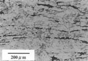
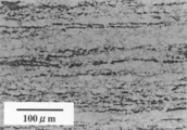
- Example Alloy No. 2 is an etching surface photograph showing a metal structure of a hot-work material A used for manufacturing 201.
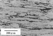
- FIG. 2 is an etching surface photograph showing the metal structure of the primary heat treatment material A1-2 obtained by the manufacturing process 201.
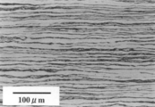
- 3 shows Example Alloy No. It is an etching surface photograph which shows the metal structure of the heat processing material which heat-processed on the raw material A of 201 on the conditions different from process M2.
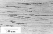
- 4 shows Example Alloy No. It is an etching photograph which shows the metal structure of the cold work material which performed the cold rolling similar to the process M2 without heat-processing to the raw material 201 of 201.
- Example Alloy No. 2 is an etching surface photograph showing the metal structure of the primary cold-worked material A2-2 for 201.
- 6 shows Example Alloy No. 2 is an etching surface photograph showing the metal structure of the secondary heat treatment material A3-2 obtained by the manufacturing process 201.
- 7 shows Example Alloy No. 20 is an etching surface photograph showing a metal structure of a heat-treated material obtained by subjecting the primary cold-worked material A2-2 obtained by the manufacturing process 201 to heat treatment under conditions different from those in the step M2.
- 8 is an etching showing the metal structure of the heat-treated material obtained by subjecting the cold-worked material (primary cold-worked material A2-2 for Example Alloy No. 201) shown in FIG. It is a face photograph.
- step 9 is an etching showing the metal structure of the heat-treated material obtained by subjecting the cold-worked material shown in FIG. 4 (the material which has been cold-worked without being heat-treated) to the heat-treated material under the same conditions as in step M2. It is a photograph.
- the silver-white copper according to the present invention is obtained by subjecting a plurality of hot-worked materials A and B and continuous cast materials C and D to one or more heat treatments and cold workings according to the following steps M1 to M25.
- Alloy hereinafter referred to as “Example Alloy”
- Each hot-work material A has an alloy composition shown in Table 1 or 2, and a plate ingot having a thickness of 190 mm, a width of 630 mm, and a length of 2000 mm is heated to 800 ° C. and hot-rolled. Thickness: 12 mm rolled sheet material obtained by processing.
- Each hot-work material B has the alloy composition shown in Table 2 or Table 3. After chamfering a cylindrical ingot having a diameter of 100 m and a length of 150 mm to a diameter of 96 mm, 800 mm It is a hot extruded rod with a diameter of 23 mm obtained by heating to ° C. and hot extrusion.
- Each continuous casting material C has an alloy composition shown in Table 3 or Table 4, and is obtained by continuous casting with a horizontal continuous casting machine and having a thickness of 40 mm, a width of 100 mm, and a length of 200 mm. It is a board material.
- each continuous casting material D has an alloy composition shown in Table 4 or Table 5, and has a thickness of 15 mm, a width of 100 mm, and a length of 200 mm obtained by continuous casting with a horizontal continuous casting machine. It is a board material.
- the first heat treatment material A was subjected to the first heat treatment to obtain a primary heat treatment material A1-1.
- This heat treatment includes a heating process in which the material A is heated at 650 ° C. for 12 hours, and a cooling process in which the material A is gradually cooled to 500 ° C. at an average cooling rate of 0.4 ° C./min.
- the primary heat-treated material A1-1 was chamfered to a thickness of 11 mm, and this was subjected to a cold rolling process as the first cold working to obtain a primary cold of a thickness of 3.25 mm. Work material A2-1 was obtained.
- the processing rate at this time is 70%.
- a second heat treatment material A3-1 was obtained by subjecting the primary cold-worked material A2-1 to a second heat treatment (final heat treatment).
- This heat treatment includes a heating process in which the primary cold-worked material A2-1 is heated at 565 ° C. for 16 hours, and a cooling process in which it is gradually cooled to 500 ° C. at an average cooling rate of 0.3 ° C./min.
- the second heat treatment material A3-1 was subjected to the second cold rolling process, and an example alloy No. having a thickness of 2.6 mm was obtained. 101-No. 104 was obtained. The processing rate at this time is 20%.
- Example Alloy No. which is the hot-worked product (hot rolled material) thus obtained.
- 101-No. The alloy composition of 104 is as shown in Table 1.
- the hot-work material A was subjected to the first heat treatment to obtain a primary heat treatment material A1-2.
- This heat treatment includes a heating process in which the material A is heated at 675 ° C. for 6 hours, and a cooling process in which the material A is gradually cooled to 500 ° C. at an average cooling rate of 0.4 ° C./min.
- the primary heat-treated material A1-2 was chamfered to a thickness of 11 mm, and the first cold-rolled material was subjected to a first cold rolling process to obtain a primary cold-worked material A2- having a thickness of 3.25 mm. 2 was obtained.
- the processing rate at this time is 70%.
- the second cold-treated material A2-2 was subjected to the second heat treatment (final heat treatment) to obtain a secondary heat-treated material A3-2.
- This heat treatment includes a heating process in which the primary cold-worked material A2-2 is heated at 575 ° C. for 3 hours, and a cooling process in which it is gradually cooled to 500 ° C. at an average cooling rate of 0.3 ° C./min.
- the second heat treatment material A3-2 was subjected to the second cold rolling process, and an example alloy No. having a thickness of 2.6 mm was obtained. 201-No. 215 was obtained. The processing rate at this time is 20%.
- Example Alloy No. which is the hot-worked product (hot rolled material) thus obtained.
- 201-No. The alloy composition of 215 is as shown in Table 1.
- the first heat treatment material A was subjected to the first heat treatment to obtain a primary heat treatment material A1-3.
- the material A is heated at 675 ° C. for 6 hours, and gradually cooled to 500 ° C. at an average cooling rate of 0.4 ° C./min. Hold at 530 ° C. in cooling, and further cool to 500 ° C. at 0.4 ° C./min.(Do not reheat to 530 ° C.)
- the cooling step holds at 530 ° C. for 1 hour.
- the primary heat-treated material A1-3 was chamfered to a thickness of 11 mm, and the first cold-rolled material was subjected to a first cold rolling process to obtain a primary cold-worked material A2- having a thickness of 3.25 mm. 3 was obtained.
- the processing rate at this time is 70%.
- a second heat treatment was performed on the primary cold-worked material A2-3 to obtain a secondary heat-treated material A3-3.
- the primary cold-worked material A2-3 is heated at 575 ° C. for 3 hours, gradually cooled to 530 ° C. at an average cooling rate of 0.3 ° C./min, and then at 530 ° C. Holding for 1 hour and cooling to 500 ° C. at an average cooling rate of 0.3 ° C./min (same as described in paragraph [0058] above).
- the second heat treatment material A3-3 was subjected to the second cold rolling process, and an example alloy No. having a thickness of 2.6 mm was obtained. 301-No. 303 was obtained. The processing rate at this time is 20%.
- Example alloy Nos. 301-No. The alloy composition of 303 is as shown in Table 1.
- the hot-work material A was subjected to the first heat treatment to obtain a primary heat treatment material A1-4.
- This heat treatment includes a heating process in which the material A is heated at 650 ° C. for 12 hours, and a cooling process in which the material A is gradually cooled to 500 ° C. at an average cooling rate of 0.4 ° C./min.
- the primary heat-treated material A1-4 was chamfered to a thickness of 11 mm, and the first cold-rolled material was subjected to a first cold rolling process to obtain a primary cold-worked material A2-4 having a thickness of 5 mm. Obtained.
- the processing rate at this time is 55%.
- a second heat treatment material A3-4 was obtained by subjecting the primary cold-worked material A2-4 to a second heat treatment.
- This heat treatment includes a heating process in which the primary cold-worked material A2-4 is heated at 575 ° C. for 3 hours, and a cooling process in which it is gradually cooled to 500 ° C. at an average cooling rate of 0.3 ° C./min.
- the second heat treatment material A3-4 was subjected to a second cold rolling process to obtain a secondary cold work material A4-4 having a thickness of 3.25 mm.
- the processing rate at this time is 35%.
- a third heat treatment material A5-4 was obtained by subjecting the secondary cold worked material A4-4 to a third heat treatment (final heat treatment).
- This heat treatment includes a heating step of heating the secondary cold-worked material A4-4 at 565 ° C. for 8 hours, and a cooling step of gradually cooling to 500 ° C. at an average cooling rate of 0.3 ° C./min. .
- the third heat treatment material A5-4 was subjected to the third cold rolling process, and an example alloy No. having a thickness of 2.6 mm was obtained. 401, no. 402 was obtained. The processing rate at this time is 20%.
- Example Alloy No. which is the hot-worked product (hot rolled material) thus obtained.
- the alloy composition of 402 is as shown in Table 2.
- the first hot rolling material A was subjected to the first cold rolling without being subjected to heat treatment. That is, the material A is chamfered to a thickness of 11 mm, and then the first cold rolling process is performed to obtain a primary cold-worked material A2-5 having a thickness of 3.25 mm. Obtained.
- the processing rate at this time is 70%.
- the primary cold-worked material A2-5 was heat-treated to obtain a heat-treated material A3-5.
- This heat treatment includes a heating process in which the primary cold-worked material A2-5 is heated at 575 ° C. for 3 hours, and a cooling process in which it is gradually cooled to 500 ° C. at an average cooling rate of 0.3 ° C./min.
- the heat treatment material A3-5 was subjected to the second cold rolling process, and the alloy No. of Example No. having a thickness of 2.6 mm was obtained. 501-No. 503 was obtained. The processing rate at this time is 20%.
- Example Alloy No. which is the hot-worked product (hot rolled material) thus obtained.
- 501-No. The alloy composition of 503 is as shown in Table 2.
- the first heat treatment material A was subjected to the first heat treatment to obtain a primary heat treatment material A1-6.
- This heat treatment includes a heating process in which the material A is heated at 540 ° C. for 6 hours, and a cooling process in which the material A is gradually cooled to 500 ° C. at an average cooling rate of 0.4 ° C./min.
- the primary heat-treated material A1-6 was chamfered to a thickness of 11 mm, and the first cold-rolled material was subjected to a first cold rolling process to obtain a primary cold-worked material A2- having a thickness of 3.25 mm. 6 was obtained.
- the processing rate at this time is 70%.
- the second cold-treated material A2-6 was subjected to a second heat treatment to obtain a secondary heat-treated material A3-6.
- This heat treatment includes a heating process in which the primary cold-worked material A2-6 is heated at 575 ° C. for 3 hours, and a cooling process in which it is gradually cooled to 500 ° C. at an average cooling rate of 0.3 ° C./min.
- the second heat treatment material A3-6 was subjected to the second cold rolling process, and an example alloy No. having a thickness of 2.6 mm was obtained. 601, no. 602 was obtained. The processing rate at this time is 20%.
- Example Alloy No. which is the hot-worked product (hot rolled material) thus obtained.
- the alloy composition of 602 is as shown in Table 2.
- the first heat treatment material A was subjected to the first heat treatment to obtain a primary heat treatment material A1-7.
- the material A was heated at 675 ° C. for 6 hours and then air-cooled.
- the average cooling rate from 675 ° C. to 500 ° C. was 10 ° C./min.
- the primary heat-treated material A1-7 was chamfered to a thickness of 11 mm, and the first cold-rolling process was performed on the primary heat-treated material A1-7 to obtain a thickness of 3.25 mm. 7 was obtained.
- the processing rate at this time is 70%.
- the second cold-treated material A2-7 was subjected to the second heat treatment to obtain a secondary heat-treated material A3-7.
- This heat treatment includes a heating process in which the primary cold-worked material A2-7 is heated at 575 ° C. for 3 hours, and a cooling process in which it is gradually cooled to 500 ° C. at an average cooling rate of 0.3 ° C./min.
- the second heat treatment material A3-7 was subjected to the second cold rolling process, and an example alloy No. having a thickness of 2.6 mm was obtained. 701, no. 702 was obtained. The processing rate at this time is 20%.
- Example Alloy No. which is the hot-worked product (hot rolled material) thus obtained.
- the alloy composition of 702 is as shown in Table 2.
- the first heat treatment material A was subjected to the first heat treatment to obtain a primary heat treatment material A1-8.
- This heat treatment includes a heating process in which the material A is heated at 675 ° C. for 6 hours, and a cooling process in which the material A is gradually cooled to 500 ° C. at an average cooling rate of 0.4 ° C./min.
- the primary heat-treated material A1-8 was chamfered to a thickness of 11 mm, and the first cold-rolled material was subjected to a first cold rolling process to obtain a primary cold-worked material A2- having a thickness of 3.25 mm. 8 was obtained.
- the processing rate at this time is 70%.
- the second cold-treated material A2-8 was subjected to a second heat treatment (490 ° C., 8 hours) to obtain a secondary heat-treated material A3-8.
- the second heat treatment material A3-8 was subjected to the second cold rolling process, and an example alloy No. having a thickness of 2.6 mm was obtained. 801, no. 802 was obtained. The processing rate at this time is 20%.
- Example Alloy No. which is the hot-worked product (hot rolled material) thus obtained.
- the alloy composition of 802 is as shown in Table 2.
- the hot-work material A was subjected to the first heat treatment to obtain a primary heat treatment material A1-9.
- This heat treatment includes a heating process in which the material A is heated at 675 ° C. for 6 hours, and a cooling process in which the material A is gradually cooled to 500 ° C. at an average cooling rate of 0.4 ° C./min.
- the primary heat-treated material A1-9 was chamfered to a thickness of 11 mm, and the first cold-rolled material was subjected to a first cold rolling process to obtain a primary cold-worked material A2- having a thickness of 3.25 mm. 9 was obtained.
- the processing rate at this time is 70%.
- the second cold-treated material A2-9 was subjected to the second heat treatment to obtain a secondary heat-treated material A3-9.
- This heat treatment includes a heating process in which the primary cold-worked material A2-9 is heated at 530 ° C. for 3 hours, and a cooling process in which it is gradually cooled to 500 ° C. at an average cooling rate of 0.3 ° C./min.
- the second heat treatment material A3-9 was subjected to the second cold rolling process, and an example alloy No. having a thickness of 2.6 mm was obtained. 901, no. 902 was obtained. The processing rate at this time is 20%.
- Example Alloy No. which is the hot-worked product (hot rolled material) thus obtained.
- the alloy composition of 902 is as shown in Table 2.
- the hot-work material B was subjected to the first heat treatment to obtain a primary heat treatment material B1-1.
- This heat treatment includes a heating process in which the material B is heated at 620 ° C. for 12 hours, and a cooling process in which the material B is gradually cooled to 500 ° C. at an average cooling rate of 0.4 ° C./min.
- the primary heat-treated material B1-1 was pickled and subjected to a drawing process as the first cold working to obtain a primary cold-worked material B2-1 having a diameter of 16.5 mm. .
- the processing rate at this time is 49%.
- the second cold-treated material B2-1 was subjected to the second heat treatment to obtain a secondary heat-treated material B3-1.
- This heat treatment includes a heating step of heating the primary cold-worked material B2-1 at 560 ° C. for 16 hours and a cooling step of gradually cooling to 500 ° C. at an average cooling rate of 0.3 ° C./min.
- the second heat treatment material B3-1 was subjected to a second drawing process to obtain an example alloy No. 1 with a diameter of 14.5 mm. 1001-No. 1007 was obtained.
- the processing rate at this time is 23%.
- the alloy composition of 1007 is as shown in Table 2.
- the first heat treatment material B was subjected to the first heat treatment to obtain a primary heat treatment material B1-2.
- This heat treatment includes a heating process in which the material B is heated at 635 ° C. for 6 hours, and a cooling process in which the material B is gradually cooled to 500 ° C. at an average cooling rate of 0.4 ° C./min.
- the primary heat-treated material B1-2 was pickled and subjected to a first drawing process to obtain a primary cold-worked material B2-2 having a diameter of 16.5 mm.
- the processing rate at this time is 49%.
- a second heat treatment B3-2 was obtained by subjecting the primary cold-worked material B2-2 to a second heat treatment.
- This heat treatment includes a heating process in which the primary cold-worked material B2-2 is heated at 575 ° C. for 6 hours, and a cooling process in which the primary cold-worked material B2-2 is gradually cooled to 500 ° C. at an average cooling rate of 0.3 ° C./min.
- Example Alloy No. 1 with a diameter of 14.5 mm. 1101-No. 1108 was obtained.
- the processing rate at this time is 23%.
- the alloy composition of 1108 is as shown in Table 2 or Table 3.
- the hot-drawn material B was subjected to a first drawing process without being subjected to heat treatment. That is, the material B was pickled and subjected to a first drawing process to obtain a primary cold-worked material B2-3 having a diameter of 16.5 mm. The processing rate at this time is 49%.
- the primary cold-worked material B2-3 was heat-treated to obtain a heat-treated material B3-3.
- This heat treatment includes a heating process in which the primary cold-worked material B2-3 is heated at 560 ° C. for 16 hours and a cooling process in which it is gradually cooled to 500 ° C. at an average cooling rate of 0.3 ° C./min.
- the second heat treatment material B3-3 was subjected to a second drawing process, and an example alloy No. 1 with a diameter of 14.5 mm was obtained. 1201, no. 1202 was obtained. The processing rate at this time is 23%.
- the alloy composition of 1202 is as shown in Table 3.
- the primary heat-treated material B1-4 was pickled and subjected to a first drawing process to obtain a primary cold-worked material B2-4 having a diameter of 16.5 mm.
- the processing rate at this time is 49%.
- the second cold-treated material B2-4 was subjected to the second heat treatment to obtain a secondary heat-treated material B3-4.
- This heat treatment includes a heating process in which the primary cold-worked material B2-4 is heated at 560 ° C. for 16 hours, and a cooling process in which it is gradually cooled to 500 ° C. at an average cooling rate of 0.3 ° C./min.
- the second heat treatment material B3-4 was subjected to a second drawing process, and an example alloy No. 1 with a diameter of 14.5 mm was obtained. 1301, no. 1302 was obtained. The processing rate at this time is 23%.
- the alloy composition of 1302 is as shown in Table 3.
- the casting material C was subjected to the first heat treatment to obtain a primary heat treatment material C1-1.
- This heat treatment includes a heating process in which the material C is heated at 670 ° C. for 12 hours and a cooling process in which the material C is gradually cooled to 500 ° C. at an average cooling rate of 0.4 ° C./min.
- the primary heat-treated material C1-1 was chamfered to a thickness of 36 mm, and then subjected to a cold rolling process, which is the first cold working, to obtain a primary cold-worked material having a thickness of 18 mm. C2-1 was obtained.
- the processing rate at this time is 50%.
- a second heat treatment was performed on the primary cold-worked material C2-1 to obtain a secondary heat-treated material C3-1.
- This heat treatment includes a heating process in which the primary cold-worked material C2-1 is heated at 565 ° C. for 16 hours, and a cooling process in which it is gradually cooled to 500 ° C. at an average cooling rate of 0.3 ° C./min.
- the second heat treatment material C3-1 was subjected to the second cold rolling process to obtain an example alloy No. 1 having a thickness of 14.5 mm. 1401-No. 1408 was obtained.
- the processing rate at this time is 19%.
- Example Alloy No. which is the continuous casting thus obtained. 1401-No.
- the alloy composition of 1408 is as shown in Table 3.
- the casting material C was subjected to the first heat treatment to obtain a primary heat treatment material C1-2.
- This heat treatment includes a heating process in which the material C is heated at 700 ° C. for 6 hours, and a cooling process in which the material C is gradually cooled to 500 ° C. at an average cooling rate of 0.4 ° C./min.
- the primary heat-treated material C1-2 is chamfered to have a thickness of 36 mm, and the first cold-rolled material is subjected to a first cold rolling process to obtain a primary cold-worked material C2-2 having a thickness of 18 mm. Obtained.
- the processing rate at this time is 50%.
- a second heat treatment was performed on the primary cold worked material C2-2 to obtain a secondary heat treated material C3-2.
- This heat treatment includes a heating process in which the primary cold-worked material C2-2 is heated at 580 ° C. for 6 hours, and a cooling process in which the primary cold-worked material C2-2 is gradually cooled to 500 ° C. at an average cooling rate of 0.3 ° C./min.
- the second heat treatment material C3-2 was subjected to the second cold rolling process to obtain an example alloy No. 1 having a thickness of 14.5 mm. 1501-No. 1509 was obtained.
- the processing rate at this time is 19%.
- Example Alloy No. which is the continuous casting thus obtained.
- 1501-No. The alloy composition of 1509 is as shown in Table 3 or Table 4.
- the hot-work material C was subjected to the first cold rolling without being subjected to heat treatment. That is, the material C was chamfered to a thickness of 36 mm, and then the first cold rolling process was performed to obtain a primary cold-worked material C2-3 having a thickness of 18 mm. .
- the processing rate at this time is 50%.
- the primary cold-worked material C2-3 was heat-treated to obtain a heat-treated material C3-3.
- This heat treatment includes a heating process in which the primary cold-worked material C2-3 is heated at 580 ° C. for 6 hours, and a cooling process in which the material is gradually cooled to 500 ° C. at an average cooling rate of 0.3 ° C./min.
- the second cold rolling process was applied to the heat treatment material C3-3 to obtain an example alloy No. 1 having a thickness of 14.5 mm. 1601, No. 1 1602 was obtained.
- the processing rate at this time is 19%.
- the casting material D was subjected to the first heat treatment to obtain a primary heat treatment material D1-1.
- This heat treatment includes a heating process in which the material D is heated at 650 ° C. for 12 hours, and a cooling process in which the material D is gradually cooled to 500 ° C. at an average cooling rate of 0.4 ° C./min.
- the primary heat-treated material D1-1 was chamfered to have a thickness of 11 mm, and the first cold-rolled material was subjected to a first cold rolling process to obtain a primary cold-worked material D2- having a thickness of 3.25 mm. 1 was obtained.
- the processing rate at this time is 70%.
- a second heat treatment material D3-1 was obtained by subjecting the primary cold-worked material D2-1 to a second heat treatment (final heat treatment).
- This heat treatment includes a heating process in which the primary cold-worked material D2-1 is heated at 565 ° C. for 16 hours, and a cooling process in which it is gradually cooled to 500 ° C. at an average cooling rate of 0.3 ° C./min.
- the second heat treatment material D3-1 was subjected to the second cold rolling process, and an example alloy No. having a thickness of 2.6 mm was obtained. 1701-No. 1706 was obtained. The processing rate at this time is 20%.
- the casting material D was subjected to the first heat treatment to obtain a primary heat treatment material D1-2.
- This heat treatment includes a heating process in which the material D is heated at 675 ° C. for 6 hours, and a cooling process in which the material D is gradually cooled to 500 ° C. at an average cooling rate of 0.4 ° C./min.
- the primary heat-treated material D1-2 was chamfered to have a thickness of 11 mm, and the first cold-rolled material was subjected to a first cold rolling process to obtain a primary cold-worked material D2- having a thickness of 3.25 mm. 2 was obtained.
- the processing rate at this time is 70%.
- the second cold-treated material D2-2 was subjected to the second heat treatment (final heat treatment) to obtain a secondary heat-treated material D3-2.
- This heat treatment includes a heating process in which the primary cold-worked material D2-2 is heated at 575 ° C. for 3 hours, and a cooling process in which it is gradually cooled to 500 ° C. at an average cooling rate of 0.3 ° C./min.
- the second heat treatment material D3-2 was subjected to the second cold rolling process, and an example alloy No. having a thickness of 2.6 mm was obtained. 1801-No. 1813 was obtained. The processing rate at this time is 20%.
- Example Alloy No. which is the continuous casting thus obtained.
- 1801-No. The alloy composition of 1813 is as shown in Table 4 or Table 5.
- the casting material D was subjected to the first heat treatment to obtain a primary heat treatment material D1-3.
- the material D is heated at a temperature of 675 ° C. for 6 hours, and gradually cooled to 500 ° C. at an average cooling rate of 0.4 ° C./min. Hold at 530 ° C. in cooling, and further cool to 500 ° C. at 0.4 ° C./min.(Do not reheat to 530 ° C.)
- the cooling step holds at 530 ° C. for 1 hour.
- the primary heat-treated material D1-3 was chamfered to a thickness of 11 mm and subjected to a first cold rolling process to obtain a primary cold-worked material D2- having a thickness of 3.25 mm. 3 was obtained.
- the processing rate at this time is 70%.
- a second heat treatment material D3-3 was obtained by subjecting the primary cold-worked material D2-3 to a second heat treatment (final heat treatment).
- This heat treatment includes a heating process in which the primary cold-worked material D2-3 is heated at 575 ° C. for 3 hours, and is gradually cooled to 530 ° C. at an average cooling rate of 0.3 ° C./min and then at 530 ° C. for 1 hour. Holding and cooling to 500 ° C. at an average cooling rate: 0.3 ° C./min (same as described in paragraph [0058] above).
- the second heat treatment material D3-3 was subjected to the second cold rolling process, and an example alloy No. having a thickness of 2.6 mm was obtained. 1901, no. 1902 was obtained. The processing rate at this time is 20%.
- the hot-work material D was subjected to the first heat treatment to obtain a primary heat treatment material D1-4.
- This heat treatment includes a heating process in which the material D is heated at 650 ° C. for 12 hours, and a cooling process in which the material D is gradually cooled to 500 ° C. at an average cooling rate of 0.4 ° C./min.
- the primary heat-treated material D1-4 was chamfered to a thickness of 11 mm, and the first cold-rolled material was subjected to a first cold rolling process to obtain a primary cold-worked material D2-4 having a thickness of 5 mm. Obtained.
- the processing rate at this time is 55%.
- the second cold-treated material D2-4 was subjected to a second heat treatment to obtain a secondary heat-treated material D3-4.
- This heat treatment includes a heating process in which the primary cold-worked material D2-4 is heated at 575 ° C. for 3 hours, and a cooling process in which it is gradually cooled to 500 ° C. at an average cooling rate of 0.3 ° C./min.
- the second heat treatment material D3-4 was subjected to a second cold rolling process to obtain a secondary cold work material D4-4 having a thickness of 3.25 mm.
- the processing rate at this time is 35%.
- the third cold-treated material D4-4 was subjected to a third heat treatment (final heat treatment) to obtain a third heat-treated material D5-4.
- This heat treatment includes a heating process in which the secondary cold-worked material D4-4 is heated at 565 ° C. for 8 hours, and a cooling process in which it is gradually cooled to 500 ° C. at an average cooling rate of 0.3 ° C./min. .
- the third heat treatment material D5-4 was subjected to the third cold rolling process, and an example alloy No. having a thickness of 2.6 mm was obtained. 2001-No. 2003 was obtained. The processing rate at this time is 20%.
- the hot-work material D was subjected to the first cold rolling without being subjected to heat treatment. That is, the material D is chamfered to a thickness of 11 mm, and then the first cold rolling process is performed to obtain a primary cold-worked material D2-5 having a thickness of 3.25 mm. Obtained.
- the processing rate at this time is 70%.
- the primary cold-worked material D2-5 was heat-treated to obtain a heat-treated material D3-5.
- This heat treatment includes a heating process in which the primary cold-worked material D2-5 is heated at 575 ° C. for 3 hours, and a cooling process in which it is gradually cooled to 500 ° C. at an average cooling rate of 0.3 ° C./min.
- the heat treatment material D3-5 was subjected to the second cold rolling process, and an example alloy No. having a thickness of 2.6 mm was obtained. 2101-No. 2105 was obtained. The processing rate at this time is 20%.
- the casting material D was subjected to the first heat treatment to obtain a primary heat treatment material D1-6.
- This heat treatment includes a heating process in which the material D is heated at 540 ° C. for 6 hours, and a cooling process in which the material D is gradually cooled to 500 ° C. at an average cooling rate of 0.4 ° C./min.
- the primary heat-treated material D1-6 was chamfered to a thickness of 11 mm and subjected to a first cold rolling process to obtain a primary cold-worked material D2- having a thickness of 3.25 mm. 6 was obtained.
- the processing rate at this time is 70%.
- a second heat treatment material D3-6 was obtained by subjecting the primary cold-work material D2-6 to the second heat treatment (final heat treatment).
- This heat treatment includes a heating process in which the primary cold-worked material D2-6 is heated at 575 ° C. for 3 hours, and a cooling process in which it is gradually cooled to 500 ° C. at an average cooling rate of 0.3 ° C./min.
- the second heat treatment material D3-6 was subjected to the second cold rolling process, and an example alloy No. having a thickness of 2.6 mm was obtained. 2201, No. 2 2202 was obtained. The processing rate at this time is 20%.
- the hot-work material D was subjected to the first heat treatment to obtain a primary heat treatment material D1-7.
- the material D was heated at 675 ° C. for 6 hours and then air-cooled.
- the average cooling rate from 675 ° C. to 500 ° C. was 10 ° C./min.
- the primary heat-treated material D1-7 was chamfered to a thickness of 11 mm, and the first cold-rolled material was subjected to the first cold rolling process to obtain a primary cold-worked material D2- having a thickness of 3.25 mm. 7 was obtained.
- the processing rate at this time is 70%.
- the second cold-treated material D2-7 was subjected to the second heat treatment to obtain a secondary heat-treated material D3-7.
- This heat treatment includes a heating process in which the primary cold-worked material D2-7 is heated at 575 ° C. for 3 hours, and a cooling process in which it is gradually cooled to 500 ° C. at an average cooling rate of 0.3 ° C./min. An average cooling rate up to 500 ° C .: a cooling step of slow cooling at 0.3 ° C./min.
- the second heat treatment material D3-7 was subjected to the second cold rolling process, and an example alloy No. having a thickness of 2.6 mm was obtained. 2301, No. 2 2302 was obtained. The processing rate at this time is 20%.
- the hot-work material D was subjected to the first heat treatment to obtain a primary heat treatment material D1-8.
- This heat treatment includes a heating process in which the material D is heated at 675 ° C. for 6 hours, and a cooling process in which the material D is gradually cooled to 500 ° C. at an average cooling rate of 0.4 ° C./min.
- the primary heat treatment material D1-8 was chamfered to a thickness of 11 mm, and this was subjected to a cold rolling process as a first cold working to obtain a primary cold of a thickness of 3.25 mm. Work material D2-8 was obtained.
- the processing rate at this time is 70%.
- the second cold-treated material D2-8 was subjected to the second heat treatment (490 ° C., 8 hours) to obtain a secondary heat-treated material D3-8.
- the second heat treatment material D3-8 was subjected to the second cold rolling process, and an example alloy No. having a thickness of 2.6 mm was obtained. 2401-No. 2403 was obtained. The processing rate at this time is 20%.
- the hot-work material D was subjected to the first heat treatment to obtain a primary heat treatment material D1-9.
- This heat treatment includes a heating process in which the material D is heated at 675 ° C. for 6 hours, and a cooling process in which the material D is gradually cooled to 500 ° C. at an average cooling rate of 0.4 ° C./min.
- the primary heat-treated material D1-9 was chamfered to a thickness of 11 mm, and then subjected to a cold rolling process as the first cold working to obtain a primary cold of a thickness of 3.25 mm. Work material D2-9 was obtained.
- the processing rate at this time is 70%.
- the second cold-treated material D2-9 was subjected to a second heat treatment to obtain a secondary heat-treated material D3-9.
- This heat treatment includes a heating process in which the primary cold-worked material D2-9 is heated at 530 ° C. for 3 hours, and a cooling process in which the material is gradually cooled to 500 ° C. at an average cooling rate of 0.3 ° C./min.
- the second heat treatment material D3-9 was subjected to the second cold rolling process, and an example alloy No. having a thickness of 2.6 mm was obtained. 2501, No. 2 2502 was obtained. The processing rate at this time is 20%.
- a copper alloy (hereinafter referred to as “comparative example alloy”) No. 1 shown in Tables 6 and 7 is used.
- Comparative Example Alloy No. 3001-No. 3008 is a hot work product manufactured by the same process M2 as in the above example using the hot work material A having the same shape obtained in the same process as in the above example except that the alloy composition is different. (Hot rolled material).
- Each Comparative Example Alloy No. 3001-No. Table 6 shows the alloy composition of 3008 and the material A used for its production.
- Comparative Example Alloy No. 3101-No. 3108 is a hot-worked product manufactured by the same process M5 as in the above-described example using the hot-work material A having the same shape obtained by the same process as in the above-described example except that the alloy composition is different. (Hot rolled material).
- Each Comparative Example Alloy No. 3101-No. Table 6 shows the alloy composition of 3108 and the material A used for its production.
- Comparative Example Alloy No. 3201-No. 3203 is a hot-worked product manufactured by the same process M10 as in the above-described example using the hot-work material B having the same shape obtained by the same process as in the above-described example except that the alloy composition is different. (Hot extruded material).
- Each Comparative Example Alloy No. 3201-No. Table 6 shows the alloy composition of 3203 and the material B used for its production.
- Comparative Example Alloy No. 3301, no. 3302 is a hot work product manufactured by the same process M12 as in the above example using the hot work material B having the same shape obtained in the same process as in the above example except that the alloy composition is different. (Hot extruded material).
- Each Comparative Example Alloy No. 3301, no. Table 6 shows the alloy composition of 3302 and the material B used for its production.
- Comparative Example Alloy No. 3401, no. 3402 is a continuous casting produced by the same process M14 as the above example using the same shape continuous casting material C obtained by the same process as the above example except that the alloy composition is different. .
- Each Comparative Example Alloy No. 3401, no. Table 7 shows the alloy composition of 3402 and the material C used for its production.
- Comparative Example Alloy No. 3501-No. 3503 is a continuous casting casting manufactured by the same process M15 as the said Example using the continuous casting raw material C of the same shape obtained by the same process as the said Example except the point from which an alloy composition differs. .
- Each Comparative Example Alloy No. 3501-No. Table 7 shows the alloy composition of 3503 and the material C used for its production.
- Comparative Example Alloy No. 3601-No. 3603 is a continuous casting casting manufactured by the same process M16 as the above-mentioned example using the continuous casting material C having the same shape obtained by the same process as the above-described example except that the alloy composition is different. .
- Each Comparative Example Alloy No. 3601-No. The alloy composition of 3603 and the material C used for its production is as shown in Table 7.
- Comparative Example Alloy No. 3701-No. 3707 is a continuous casting produced by the same process M18 as the above example using the same shape continuous casting material D obtained by the same process as the above example except that the alloy composition is different. .
- Each Comparative Example Alloy No. 3701-No. Table 7 shows the alloy composition of 3707 and the material D used for its production.
- Comparative Example Alloy No. 3801 is a continuous casting casting manufactured by the same process M21 as the said Example using the continuous casting raw material D of the same shape obtained by the same process as the said Example except the point from which an alloy composition differs. . Comparative Example Alloy No.
- the alloy composition of 3801 and the material D used for its production is as shown in Table 7.
- Comparative Example Alloy No. 3901-No. 3903 is a commercial grade H material having a thickness of 2.4 mm and having an alloy composition shown in Table 7.
- 3904-No. 3906 is a 15 mm diameter commercial bar material having the alloy composition shown in Table 5.
- no. 3901 is CDA C79200
- No. 3902 is JIS C3710
- No. 3903 is JIS C2801
- No. 3904 is CDA C79200
- No. 3905 is JIS C3712
- No. 3906 corresponds to JIS C2800.
- FIG. 1 and FIG. 2 is an etching surface photograph of 201.
- FIG. 1 shows the metal structure of the hot-work material A, and it can be understood from FIG. 1 that the ⁇ phase in the material A has a network shape.
- FIG. 2 shows the metal structure of the primary heat-treated material A1-2 obtained by heat-treating the raw material A at 675 ° C. As can be understood from FIG. It is understood that the ⁇ phase is dispersed and the proportion of the ⁇ phase in the ⁇ phase is reduced due to the precipitation of the ⁇ phase.
- FIG. 3 and 4 show Example Alloy No. It is an etching surface photograph about what heat-processed or cold-worked different from the process M2 to the material A of 201.
- FIG. 3 shows a heat treatment material that was subjected to heat treatment of material A under a low temperature condition different from that in step M2 (maintained at 540 ° C. for 6 hours, gradually cooled to 500 ° C. at 0.4 ° C./second, and then air cooled)
- FIG. 4 shows the metal structure of the cold-worked material that was subjected to the same cold rolling (working rate 70%) as that in the step M2 without subjecting the material A to the heat treatment unlike the step M2. Is shown. From FIG.
- FIG. 5 shows Example Alloy No. 2 is an etching surface photograph showing the metal structure of the primary cold-worked material A2-2 for 201. From FIG. 5, it is understood that the amount of ⁇ phase is small as in the case shown in FIG. 2, and the ⁇ phase is stretched in the rolling direction by cold rolling.
- FIG. 6 is an etching surface photograph showing the metal structure of the secondary heat-treated material A3-2 obtained by heat-treating (575 ° C.) the primary processed material A2-2 shown in FIG. 5, and is compared with FIG. As is apparent, the ⁇ phase is uniformly dispersed in the ⁇ phase of the matrix, and the shape and size (average value of long side / short side, etc.) are in the optimum form as described above.
- FIG. 7 shows the cold-worked material shown in FIG. 5 (the primary cold-worked material A2-2 for Example Alloy No. 201), unlike the process M2, at a low temperature (490 ° C., 8 hours). It is an etching surface photograph which shows the metal structure of the heat processing material which gave. From FIG. 7, since it is a heat treatment at a low temperature, unlike the case shown in FIG. 6, the precipitation by the ⁇ phase is insufficient, the ⁇ phase is continuous for a long time, and conversely the ⁇ phase is centered around the grain boundary. It is understood that it has precipitated.
- FIG. 8 shows that the cold-worked material shown in FIG. 5 (the primary cold-worked material A2-2 for Example Alloy No. 201) is subjected to a temperature condition lower than the heat treatment temperature (575 ° C.) in Step M2. It is an etching surface photograph which shows the metal structure of the heat processing material which performed the heat processing (530 degreeC, 3 hours, the average cooling rate to 500 degreeC: 0.4 degreeC / min).
- FIG. 9 shows the heat treatment (575 ° C., 3 hours, up to 500 ° C.) under the same conditions as in step M2 on the cold-worked material shown in FIG. 4 (the material was cold-worked without being heat-treated). It is an etching photograph which shows the metal structure of the heat processing material which gave (average cooling rate: 0.4 degree-C / min). From FIG. 9, ⁇ phase is precipitated by heat treatment and ⁇ phase splitting (dissolution of network form) is progressing, but ⁇ phase is still long and long side / short side is large and not enough. The disadvantage of not heat treating the material A before cold working is clearly understood.
- the proportion of the ⁇ phase in the materials A, B, C, D (hereinafter referred to as “material ⁇ phase ratio”), the long side / short side ratio of the ⁇ phase (long side) / Average value of short side) and the number of ⁇ phases having a long side of 0.5 mm or more per 0.1 mm 2 (hereinafter referred to as “number of ⁇ phases of 0.5 mm or more”) and materials A and B , C, and D were measured for the proportion of ⁇ -phase in the heat-treated material (hereinafter referred to as “ ⁇ -phase ratio after heat treatment”), and the proportion of ⁇ -phase in the product (before finishing) (hereinafter “ Product ⁇ phase ratio), ⁇ phase area (average area of ⁇ phase), long side / short side ratio (average value of long side / short side of ⁇ phase), 12 or less ⁇ phase ratio (long side / short side) the ratio value is 12 or less and comprising ⁇ -phase of
- the average crystal grain size was determined by the FE-SEM-EBSP (Electron Back Scattering Diffraction Pattern) method. That is, FE-SEM is JSM-7000F manufactured by JEOL Ltd., and TSL Solutions OIM-Ver. 5.1 was used, and the average crystal grain size was determined from a grain size map (Grain map) with an analysis magnification of 200 times and 500 times. The calculation method of the average crystal grain size is based on the quadrature method (JIS H 0501).
- ⁇ phase rate The proportion of ⁇ phase ( ⁇ phase rate) was determined by the FE-SEM-EBSP method.
- FE-SEM is JSM-7000F manufactured by JEOL Ltd., and OIM-Ver. 5.1 was used, and it was obtained from a phase map (Phase map) with an analysis magnification of 200 times and 500 times.
- the length (long side, short side) and area of the ⁇ phase were determined by the FE-SEM-EBSP method. Binarization was performed from the phase map with the analysis magnification of 200 times and 500 times by the image processing software “WinROOF”, and the maximum length of the ⁇ phase and the ratio of the long side length to the short side length were obtained.
- the hot / cold workability, torsional strength, impact strength, bendability, wear resistance, press formability, machinability and the like were confirmed as follows.
- torsional strength For torsional strength, torsional test pieces (length: 320 mm, chuck part diameter: 14.1 mm, parallel part diameter: 7.8 mm, parallel part length: 100 mm) were taken from the example alloys and comparative example alloys. Then, a torsional test was performed to determine a torsional strength when the permanent deformation was 1 ° (hereinafter referred to as “1 ° torsional strength”) and a torsional strength at 45 ° (hereinafter referred to as “45 ° torsional strength”). The results were as shown in Tables 6-10.
- An impact test piece (V-notch test piece according to JIS Z2242) was taken from the above-described Example alloy and Comparative example alloy, and a Charpy impact test was performed to measure the impact strength. The results are as shown in Tables 15 to 19 and Tables 25 and 26. It was confirmed that the example alloys satisfying the relational expressions of f1 to f4, the amount of ⁇ phase, and the shape were excellent in impact resistance.
- Test pieces were sampled from the example alloys and comparative example alloys, and subjected to wear tests using a ball-on-disk wear tester (manufactured by Shinko Engineering Co., Ltd.).
- a wear test was conducted using a 10 mm diameter SUS304 ball as a sliding material, applying a load of 5 kgf (49 N), non-lubricated, wear speed of 0.1 m / min, 10 mm diameter circumferential rotational wear to 250 m sliding distance. The difference was calculated as the amount of wear by measuring the weight before and after the test.
- the results are as shown in Tables 15 to 19 and Tables 25 and 26, and it was confirmed that the example alloys were excellent in wear resistance.
- a sagging area of 0.18 mm or less (7% of the plate thickness) is indicated by “ ⁇ ” as having good press formability, and the area exceeds 0.1 mm and is less than 0.26 mm ( A sheet having a thickness of 10%) is indicated by “ ⁇ ” as being capable of press formability, and “X” is indicated by being “6” when the area is 0.26 mm or more.
- burrs when there is no burrs, “ ⁇ ” indicates that the press moldability is good, and when the burrs are less than 0.01 mm, the press moldability is “ A symbol “ ⁇ ” indicates that the height of the burrs is 0.01 mm or more, and “ ⁇ ” indicates that press formability is impossible.
- ⁇ indicates that the press formability is good if it is 0.07 mm or less, and the press formability indicates that the dimensional difference is more than 0.07 mm and less than 0.11 mm. Is indicated by “ ⁇ ”, and those having a dimensional difference of 0.11 mm or more are indicated by “x” because the press formability is not possible.
- the fracture surface is a shear or fracture surface, but in the example alloys, the proportion of the fracture surface is basically 75% or more. Furthermore, it is of course better for the tool life to have a larger number of fractured surfaces. However, if the ⁇ phase rate and ⁇ phase shape are appropriate, uniform fracture occurs during press molding, so there are many fractured surfaces. It is understood that good press forming is performed in the example alloys that are considered to occur and satisfy the relational expressions of f1 to f4, the amount of ⁇ phase, and the shape.
- a drill cutting test piece (14.5 mm thick plate and 14.5 mm diameter rod) was taken from the example alloy and the comparative example alloy, and a drill cutting test was performed without lubrication to measure the torque of the drill. That is, using a JIS standard drill manufactured by Heiss, a drill hole having a diameter of 3.5 mm and a depth of 10 mm was drilled under the conditions of a rotational speed of 1250 rpm and a feed of 0.07 mm / rev. The generated torque was converted into an electric signal and recorded on a recorder, which was converted into torque again. The results were as shown in Tables 20 to 24 and Tables 27 and 28.
- Stress corrosion cracking resistance A test piece similar to the above-mentioned bending test piece was taken from the example alloy and the comparative example alloy, and a 90-degree bent one was used, and a stress corrosion cracking test was conducted by a method prescribed in JIS. In other words, after exposing to ammonia using a mixture of equal amounts of ammonia water and water, washing with sulfuric acid, the presence of cracks was investigated with a 10-fold stereo microscope, and stress corrosion cracking resistance was evaluated. It was. The results were as shown in Tables 20 to 24 and Tables 27 and 28 (shown as “stress corrosion cracking” in the table).
- the amount of ⁇ phase and the shape of ⁇ phase have predetermined requirements. In many cases, it is not satisfied, and press formability and machinability are poor. Even if the ⁇ phase requirement is satisfied, if the amount of Mn and the Mn / Ni ratio are outside the scope of the present invention, hot or cold workability, bendability, press formability, machinability, and wear resistance At least one of them, many of which have a plurality of poor characteristics. If the Cu concentration or the value of f1 is high, the hot workability is poor, and if it is low, the cold workability and bendability are poor.
- Pb and the like can be improved in machinability and press formability with little addition of a small amount, with only a slight reduction in impact strength and without substantially damaging other properties.
- Co-addition within a preferable range including the blending ratio of Zr and P can refine the crystal grains at the casting stage, so that the ⁇ phase is divided by the first heat treatment to obtain a preferable shape, and the final product is coated. Improved machinability. Especially for continuous casting, the effect of co-addition of both elements is great.
- the alloy of the present invention obtained by satisfying the composition, f1 to f4 and subjected to appropriate heat treatment is press formability, hot / cold workability, bending characteristics, torsional strength, impact strength, wear resistance. It was possible to provide various properties necessary for applications such as keys, such as properties and corrosion resistance.
- the object color measurement method based on JIS Z 8722-1982 was carried out for the example alloys and the comparative example alloys, and the results are defined in JIS Z 8729-1980 in Tables 20 to 24 and Tables 27 and 28.
- the L, a, b color system is shown. Specifically, L, a, and b values were measured by the SCI (including regular reflection light) method using a spectrocolorimeter “CM-2002” manufactured by Minolta.
- L (saturation) increases as the added amount of Cu and Ni increases, and decreases as the added amount of Mn increases.
- the additive element becomes slightly positive when a small amount of Al is added.
- [Ni] + [Mn] ⁇ 14 is basically plus and slightly reddish.
- the negative value increases as the Ni addition amount increases or the Mn addition amount decreases. That is, in order to obtain silver whiteness, it is preferable that at least [Ni] + [Mn] is 13 or more.
- a salt spray test specified in JIS Z 2371 was performed, and color measurement was performed. That is, a 5% NaCl solution was sprayed at 35 ° C. (precisely 35 ⁇ 2 ° C.) on a sample placed in the spray chamber, taken out after a predetermined time (24 hours), and color measurement was performed with a color difference meter.
- the results are shown in Tables 20 to 24 and Tables 27 and 28.
- the object color measurement method described above was further performed on the above-described salt spray test to confirm the color change after the salt spray test. did.
- the results were as shown in Tables 20 to 24 and Tables 27 and 28 (in the table, “color difference before and after the test”).
- the salt spray reduces L (saturation) and the luster is lost. a changes in the positive direction and b also changes in the positive direction, and the color tone such as reddish brown becomes strong. That is, the entire surface is corroded by spraying with salt water, and the copper oxide-based reddish brown product is recognized due to the corrosion, the luster is lost, and the redness is increased.
- the degree of change is more conspicuous as the total amount of Ni and Mn added is smaller, and the degree of increase increases when Mn / Ni is out of the appropriate range.
- Al can contribute to improvement of corrosion resistance (small change in color difference).
- the amount of Cu the change in the positive direction of a tends to increase. From Tables 20 to 24 and Tables 27 and 28, the alloy of the example has a smaller change before and after the salt spray test than the comparative alloy for any of L, a, and b, and the color difference is 10 or less. It is understood that it has excellent resistance to discoloration.
Landscapes
- Chemical & Material Sciences (AREA)
- Engineering & Computer Science (AREA)
- Mechanical Engineering (AREA)
- Materials Engineering (AREA)
- Metallurgy (AREA)
- Organic Chemistry (AREA)
- Physics & Mathematics (AREA)
- Thermal Sciences (AREA)
- Crystallography & Structural Chemistry (AREA)
- Conductive Materials (AREA)
Abstract
Description
熱間加工素材Aに第1回目の熱処理を施して、一次熱処理材A1-1を得た。この熱処理は、素材Aを650℃,12時間の条件で加熱する加熱工程と、500℃まで平均冷却速度:0.4℃/分で徐冷する冷却工程とからなる。 (Process M1)
The first heat treatment material A was subjected to the first heat treatment to obtain a primary heat treatment material A1-1. This heat treatment includes a heating process in which the material A is heated at 650 ° C. for 12 hours, and a cooling process in which the material A is gradually cooled to 500 ° C. at an average cooling rate of 0.4 ° C./min.
熱間加工素材Aに第1回目の熱処理を施して、一次熱処理材A1-2を得た。この熱処理は、素材Aを675℃,6時間の条件で加熱する加熱工程と、500℃まで平均冷却速度:0.4℃/分で徐冷する冷却工程とからなる。 (Process M2)
The hot-work material A was subjected to the first heat treatment to obtain a primary heat treatment material A1-2. This heat treatment includes a heating process in which the material A is heated at 675 ° C. for 6 hours, and a cooling process in which the material A is gradually cooled to 500 ° C. at an average cooling rate of 0.4 ° C./min.
熱間加工素材Aに第1回目の熱処理を施して、一次熱処理材A1-3を得た。この熱処理は、素材Aを675℃,6時間の条件で加熱する加熱工程と、500℃まで平均冷却速度:0.4℃/分で徐冷した上で、その冷却途中で(500℃までの冷却中で530℃で保持し、さらに500℃まで0.4℃/分で冷却する。改めて530℃に加熱はしない。)530℃で1時間保持する冷却工程とからなる。 (Process M3)
The first heat treatment material A was subjected to the first heat treatment to obtain a primary heat treatment material A1-3. In this heat treatment, the material A is heated at 675 ° C. for 6 hours, and gradually cooled to 500 ° C. at an average cooling rate of 0.4 ° C./min. Hold at 530 ° C. in cooling, and further cool to 500 ° C. at 0.4 ° C./min.(Do not reheat to 530 ° C.) The cooling step holds at 530 ° C. for 1 hour.
熱間加工素材Aに第1回目の熱処理を施して、一次熱処理材A1-4を得た。この熱処理は、素材Aを650℃,12時間の条件で加熱する加熱工程と、500℃まで平均冷却速度:0.4℃/分で徐冷する冷却工程とからなる。 (Process M4)
The hot-work material A was subjected to the first heat treatment to obtain a primary heat treatment material A1-4. This heat treatment includes a heating process in which the material A is heated at 650 ° C. for 12 hours, and a cooling process in which the material A is gradually cooled to 500 ° C. at an average cooling rate of 0.4 ° C./min.
熱間加工素材Aに、工程M1~M4と異なって、熱処理を施すことなく、第1回目の冷間圧延加工を施した。すなわち、当該素材Aに、これを面削して厚さ:11mmとした上で、第1回目の冷間圧延加工を施して、厚さ:3.25mmの一次冷間加工材A2-5を得た。このときの加工率は70%である。 (Process M5)
Unlike the processes M1 to M4, the first hot rolling material A was subjected to the first cold rolling without being subjected to heat treatment. That is, the material A is chamfered to a thickness of 11 mm, and then the first cold rolling process is performed to obtain a primary cold-worked material A2-5 having a thickness of 3.25 mm. Obtained. The processing rate at this time is 70%.
熱間加工素材Aに第1回目の熱処理を施して、一次熱処理材A1-6を得た。この熱処理は、素材Aを540℃,6時間の条件で加熱する加熱工程と、500℃まで平均冷却速度:0.4℃/分で徐冷する冷却工程とからなる。 (Process M6)
The first heat treatment material A was subjected to the first heat treatment to obtain a primary heat treatment material A1-6. This heat treatment includes a heating process in which the material A is heated at 540 ° C. for 6 hours, and a cooling process in which the material A is gradually cooled to 500 ° C. at an average cooling rate of 0.4 ° C./min.
熱間加工素材Aに第1回目の熱処理を施して、一次熱処理材A1-7を得た。この熱処理にあっては、素材Aを675℃,6時間の条件で加熱した上で空冷した。この空冷においては、675℃から500℃までの平均冷却速度が10℃/分であった。 (Process M7)
The first heat treatment material A was subjected to the first heat treatment to obtain a primary heat treatment material A1-7. In this heat treatment, the material A was heated at 675 ° C. for 6 hours and then air-cooled. In this air cooling, the average cooling rate from 675 ° C. to 500 ° C. was 10 ° C./min.
熱間加工素材Aに第1回目の熱処理を施して、一次熱処理材A1-8を得た。この熱処理は、素材Aを675℃,6時間の条件で加熱する加熱工程と、500℃まで平均冷却速度:0.4℃/分で徐冷する冷却工程とからなる。 (Process M8)
The first heat treatment material A was subjected to the first heat treatment to obtain a primary heat treatment material A1-8. This heat treatment includes a heating process in which the material A is heated at 675 ° C. for 6 hours, and a cooling process in which the material A is gradually cooled to 500 ° C. at an average cooling rate of 0.4 ° C./min.
熱間加工素材Aに第1回目の熱処理を施して、一次熱処理材A1-9を得た。この熱処理は、素材Aを675℃,6時間の条件で加熱する加熱工程と、500℃まで平均冷却速度:0.4℃/分で徐冷する冷却工程とからなる。 (Process M9)
The hot-work material A was subjected to the first heat treatment to obtain a primary heat treatment material A1-9. This heat treatment includes a heating process in which the material A is heated at 675 ° C. for 6 hours, and a cooling process in which the material A is gradually cooled to 500 ° C. at an average cooling rate of 0.4 ° C./min.
熱間加工素材Bに第1回目の熱処理を施して、一次熱処理材B1-1を得た。この熱処理は、素材Bを620℃,12時間の条件で加熱する加熱工程と、500℃まで平均冷却速度:0.4℃/分で徐冷する冷却工程とからなる。 (Process M10)
The hot-work material B was subjected to the first heat treatment to obtain a primary heat treatment material B1-1. This heat treatment includes a heating process in which the material B is heated at 620 ° C. for 12 hours, and a cooling process in which the material B is gradually cooled to 500 ° C. at an average cooling rate of 0.4 ° C./min.
熱間加工素材Bに第1回目の熱処理を施して、一次熱処理材B1-2を得た。この熱処理は、素材Bを635℃,6時間の条件で加熱する加熱工程と、500℃まで平均冷却速度:0.4℃/分で徐冷する冷却工程とからなる。 (Process M11)
The first heat treatment material B was subjected to the first heat treatment to obtain a primary heat treatment material B1-2. This heat treatment includes a heating process in which the material B is heated at 635 ° C. for 6 hours, and a cooling process in which the material B is gradually cooled to 500 ° C. at an average cooling rate of 0.4 ° C./min.
熱間加工素材Bに、工程M11,M12と異なって、熱処理を施すことなく、第1回目の抽伸加工を施した。すなわち、当該素材Bに、これを酸洗した上で、第1回目の抽伸加工を施して、径:16.5mmの一次冷間加工材B2-3を得た。このときの加工率は49%である。 (Process M12)
Unlike the processes M11 and M12, the hot-drawn material B was subjected to a first drawing process without being subjected to heat treatment. That is, the material B was pickled and subjected to a first drawing process to obtain a primary cold-worked material B2-3 having a diameter of 16.5 mm. The processing rate at this time is 49%.
熱間加工素材Bに第1回目の熱処理(490℃,12時間)を施して、一次熱処理材B1-4を得た。 (Process M13)
The hot-work material B was subjected to the first heat treatment (490 ° C., 12 hours) to obtain a primary heat-treated material B1-4.
鋳造素材Cに第1回目の熱処理を施して、一次熱処理材C1-1を得た。この熱処理は、素材Cを670℃,12時間の条件で加熱する加熱工程と、500℃まで平均冷却速度:0.4℃/分で徐冷する冷却工程とからなる。 (Process M14)
The casting material C was subjected to the first heat treatment to obtain a primary heat treatment material C1-1. This heat treatment includes a heating process in which the material C is heated at 670 ° C. for 12 hours and a cooling process in which the material C is gradually cooled to 500 ° C. at an average cooling rate of 0.4 ° C./min.
鋳造素材Cに第1回目の熱処理を施して、一次熱処理材C1-2を得た。この熱処理は、素材Cを700℃,6時間の条件で加熱する加熱工程と、500℃まで平均冷却速度:0.4℃/分で徐冷する冷却工程とからなる。 (Process M15)
The casting material C was subjected to the first heat treatment to obtain a primary heat treatment material C1-2. This heat treatment includes a heating process in which the material C is heated at 700 ° C. for 6 hours, and a cooling process in which the material C is gradually cooled to 500 ° C. at an average cooling rate of 0.4 ° C./min.
熱間加工素材Cに、工程M14,M15と異なって、熱処理を施すことなく、第1回目の冷間圧延加工を施した。すなわち、当該素材Cに、これを面削して厚さ:36mmとした上で、第1回目の冷間圧延加工を施して、厚さ:18mmの一次冷間加工材C2-3を得た。このときの加工率は50%である。 (Process M16)
Unlike the processes M14 and M15, the hot-work material C was subjected to the first cold rolling without being subjected to heat treatment. That is, the material C was chamfered to a thickness of 36 mm, and then the first cold rolling process was performed to obtain a primary cold-worked material C2-3 having a thickness of 18 mm. . The processing rate at this time is 50%.
鋳造素材Dに第1回目の熱処理を施して、一次熱処理材D1-1を得た。この熱処理は、素材Dを650℃,12時間の条件で加熱する加熱工程と、500℃まで平均冷却速度:0.4℃/分で徐冷する冷却工程とからなる。 (Process M17)
The casting material D was subjected to the first heat treatment to obtain a primary heat treatment material D1-1. This heat treatment includes a heating process in which the material D is heated at 650 ° C. for 12 hours, and a cooling process in which the material D is gradually cooled to 500 ° C. at an average cooling rate of 0.4 ° C./min.
鋳造素材Dに第1回目の熱処理を施して、一次熱処理材D1-2を得た。この熱処理は、素材Dを675℃,6時間の条件で加熱する加熱工程と、500℃まで平均冷却速度:0.4℃/分で徐冷する冷却工程とからなる。 (Process M18)
The casting material D was subjected to the first heat treatment to obtain a primary heat treatment material D1-2. This heat treatment includes a heating process in which the material D is heated at 675 ° C. for 6 hours, and a cooling process in which the material D is gradually cooled to 500 ° C. at an average cooling rate of 0.4 ° C./min.
鋳造素材Dに第1回目の熱処理を施して、一次熱処理材D1-3を得た。この熱処理は、素材Dを675℃,6時間の条件で加熱する加熱工程と、500℃まで平均冷却速度:0.4℃/分で徐冷した上で、その冷却途中で(500℃までの冷却中で530℃で保持し、さらに500℃まで0.4℃/分で冷却する。改めて530℃に加熱はしない。)530℃に1時間保持する冷却工程とからなる。 (Process M19)
The casting material D was subjected to the first heat treatment to obtain a primary heat treatment material D1-3. In this heat treatment, the material D is heated at a temperature of 675 ° C. for 6 hours, and gradually cooled to 500 ° C. at an average cooling rate of 0.4 ° C./min. Hold at 530 ° C. in cooling, and further cool to 500 ° C. at 0.4 ° C./min.(Do not reheat to 530 ° C.) The cooling step holds at 530 ° C. for 1 hour.
熱間加工素材Dに第1回目の熱処理を施して、一次熱処理材D1-4を得た。この熱処理は、素材Dを650℃,12時間の条件で加熱する加熱工程と、500℃まで平均冷却速度:0.4℃/分で徐冷する冷却工程とからなる。 (Process M20)
The hot-work material D was subjected to the first heat treatment to obtain a primary heat treatment material D1-4. This heat treatment includes a heating process in which the material D is heated at 650 ° C. for 12 hours, and a cooling process in which the material D is gradually cooled to 500 ° C. at an average cooling rate of 0.4 ° C./min.
熱間加工素材Dに、工程M17~M20と異なって、熱処理を施すことなく、第1回目の冷間圧延加工を施した。すなわち、当該素材Dに、これを面削して厚さ:11mmとした上で、第1回目の冷間圧延加工を施して、厚さ:3.25mmの一次冷間加工材D2-5を得た。このときの加工率は70%である。 (Process M21)
Unlike the processes M17 to M20, the hot-work material D was subjected to the first cold rolling without being subjected to heat treatment. That is, the material D is chamfered to a thickness of 11 mm, and then the first cold rolling process is performed to obtain a primary cold-worked material D2-5 having a thickness of 3.25 mm. Obtained. The processing rate at this time is 70%.
鋳造素材Dに第1回目の熱処理を施して、一次熱処理材D1-6を得た。この熱処理は、素材Dを540℃,6時間の条件で加熱する加熱工程と、500℃まで平均冷却速度:0.4℃/分で徐冷する冷却工程とからなる。 (Process M22)
The casting material D was subjected to the first heat treatment to obtain a primary heat treatment material D1-6. This heat treatment includes a heating process in which the material D is heated at 540 ° C. for 6 hours, and a cooling process in which the material D is gradually cooled to 500 ° C. at an average cooling rate of 0.4 ° C./min.
熱間加工素材Dに第1回目の熱処理を施して、一次熱処理材D1-7を得た。この熱処理にあっては、素材Dを675℃,6時間の条件で加熱した上で空冷した。この空冷にあっては、675℃から500℃までの平均冷却速度が10℃/分であった。 (Process M23)
The hot-work material D was subjected to the first heat treatment to obtain a primary heat treatment material D1-7. In this heat treatment, the material D was heated at 675 ° C. for 6 hours and then air-cooled. In this air cooling, the average cooling rate from 675 ° C. to 500 ° C. was 10 ° C./min.
熱間加工素材Dに第1回目の熱処理を施して、一次熱処理材D1-8を得た。この熱処理は、素材Dを675℃,6時間の条件で加熱する加熱工程と、500℃まで平均冷却速度:0.4℃/分で徐冷する冷却工程とからなる。 (Process M24)
The hot-work material D was subjected to the first heat treatment to obtain a primary heat treatment material D1-8. This heat treatment includes a heating process in which the material D is heated at 675 ° C. for 6 hours, and a cooling process in which the material D is gradually cooled to 500 ° C. at an average cooling rate of 0.4 ° C./min.
熱間加工素材Dに第1回目の熱処理を施して、一次熱処理材D1-9を得た。この熱処理は、素材Dを675℃,6時間の条件で加熱する加熱工程と、500℃まで平均冷却速度:0.4℃/分で徐冷する冷却工程とからなる。 (Process M25)
The hot-work material D was subjected to the first heat treatment to obtain a primary heat treatment material D1-9. This heat treatment includes a heating process in which the material D is heated at 675 ° C. for 6 hours, and a cooling process in which the material D is gradually cooled to 500 ° C. at an average cooling rate of 0.4 ° C./min.
熱間加工性については、熱間圧延後の割れ状況(素材A,B,C,Dの割れ状況)により評価した。その結果は表15~19及び表25,26に示す通りであった。当該表においては、外観目視で割れ等の損傷が全くないもの又は割れがあっても微細(5mm以下)であるものについては実用性に優れるとして「○」で示し、10mm以下の耳割れが全長に渡り10箇所以下であるものについては実用可能であるとして「△」で示し、10mm以上の大きな割れ及び/又は10mm以下の小さな割れが10箇所を超えるものについては、実用性困難(実用上大きな手直しが必要)として「×」で示した。また、冷間加工性については、冷間圧延後の割れ状況(冷間加工材の割れ状況)により評価した。その結果は表6~10に示す通りであった。当該表においては、外観目視で割れ等の損傷が全くないもの又は割れがあっても微細(3mm以下)であるものについては実用性に優れるとして「○」で示し、3mmを超え7mm以下の耳割れが生じているものについては実用可能であるとして「△」で示し、鋳物の欠陥以外に7mmを超える大きな割れが生じているものについては実用性困難として「×」で示した。表15~19に示す結果から、実施例合金では、熱間加工性,冷間加工性に問題がないことが確認された。一方、比較例から、Cu濃度が高い、またはMn/Niが低いと熱間割れを生じやすくなり、Cu濃度が低い、またはMn/Niが低い、またはβ相の占める割合が高い、またはβ相の形状が悪いと冷間割れを生じやすいことが確認された。 (Hot / Cold workability)
About hot workability, it evaluated by the crack condition (cracking condition of materials A, B, C, and D) after hot rolling. The results are shown in Tables 15 to 19 and Tables 25 and 26. In the table, those that have no damage such as cracks by visual inspection or those that are fine (5 mm or less) even if there are cracks are indicated by “◯” as being excellent in practicality, and the ear cracks of 10 mm or less are the full length. Those having 10 or less locations are indicated by “Δ” as being practical, and those having large cracks of 10 mm or more and / or small cracks of 10 mm or less exceeding 10 locations are difficult to be practical (large in practical use). It is indicated by "x" as reworking is necessary. Moreover, about cold workability, it evaluated by the crack condition after a cold rolling (crack condition of a cold work material). The results were as shown in Tables 6-10. In the table, those that have no damage such as cracks by visual inspection or those that are fine (3 mm or less) even if there are cracks are marked with “○” as being excellent in practicality, and are over 3 mm and 7 mm or less. Those having cracks are indicated by “Δ” as being practical, and those having large cracks exceeding 7 mm other than casting defects are indicated by “x” as being difficult to use. From the results shown in Tables 15 to 19, it was confirmed that the example alloys had no problem in hot workability and cold workability. On the other hand, from the comparative example, when the Cu concentration is high or Mn / Ni is low, hot cracking is likely to occur, and the Cu concentration is low, Mn / Ni is low, or the proportion of β phase is high, or β phase It was confirmed that cold cracking was likely to occur when the shape of the steel was poor.
ねじり強度については、実施例合金及び比較例合金からねじり試験片(長さ:320mm,チャック部の径:14.1mm,平行部の径:7.8mm,平行部の長さ:100mm)を採取してねじり試験を行い、永久変形が1°の場合におけるねじり強度(以下「1°ねじり強度」という)と45°の場合におけるねじり強度(以下「45°ねじり強度」という)を求めた。その結果は表6~10に示す通りであった。棒材と板材との形状は異なるが、僅かの変形でもキーは挿入することが不可となり、45°の変形はキーとしての修復が不可となり、安全上も問題となる。かかるねじり試験の結果から、実施例合金では、このような問題が生じないことが確認された。 (Torsion strength)
For torsional strength, torsional test pieces (length: 320 mm, chuck part diameter: 14.1 mm, parallel part diameter: 7.8 mm, parallel part length: 100 mm) were taken from the example alloys and comparative example alloys. Then, a torsional test was performed to determine a torsional strength when the permanent deformation was 1 ° (hereinafter referred to as “1 ° torsional strength”) and a torsional strength at 45 ° (hereinafter referred to as “45 ° torsional strength”). The results were as shown in Tables 6-10. Although the shapes of the bar and the plate are different, the key cannot be inserted even with a slight deformation, and the 45 ° deformation cannot be repaired as a key, which causes a safety problem. From the result of the torsion test, it was confirmed that such a problem does not occur in the example alloys.
上記した実施例合金及び比較例合金から衝撃試験片(JIS Z2242に準じたVノッチ試験片)を採取してシャルピー衝撃試験を行い、衝撃強さを測定した。その結果は、表15~19及び表25,26に示す通りであり、f1~f4の関係式、β相の量、形状を満足する実施例合金は耐衝撃性に優れることが確認された。 (Impact resistance)
An impact test piece (V-notch test piece according to JIS Z2242) was taken from the above-described Example alloy and Comparative example alloy, and a Charpy impact test was performed to measure the impact strength. The results are as shown in Tables 15 to 19 and Tables 25 and 26. It was confirmed that the example alloys satisfying the relational expressions of f1 to f4, the amount of β phase, and the shape were excellent in impact resistance.
実施例合金及び比較例合金から曲げ試験片(厚み:2.4mm)を採取し、曲げ部の半径がt/2(1.2mm)となる治具を用いて、試験片の90°曲げを行った。その結果は、表15~19及び表25,26に示す通りであった。当該表にあっては、90°曲げによりクラックが生じなかったものについては曲げ性に優れるとして「○」で示し、開口又は破壊には至らない小さなクラックが発生したものについては一般的な曲げ性を有するものとして「△」で示し、クラックが開口又は破壊に至っているものについては曲げ性に劣るとして「×」で示した。かかる結果から、f1~f4の関係式、β相の量、形状を満足する実施例合金は曲げ性に問題がないことが確認された。なお、Cu濃度が低い、またはMn/Niが低い、またはβ相の占める割合が高い、またはβ相の形状が悪いと曲げ加工性が悪くなることが確認された。 (Bendability)
Bending test pieces (thickness: 2.4 mm) were taken from the example alloy and the comparative example alloy, and the test piece was bent at 90 ° using a jig whose radius of the bent portion was t / 2 (1.2 mm). went. The results were as shown in Tables 15 to 19 and Tables 25 and 26. In the table, “O” indicates that a crack is not generated by bending at 90 °, and “B” indicates that the bend is excellent, and general bendability is observed for a small crack that does not lead to opening or breakage. It was shown by “Δ” as having a crack, and “×” was shown as being inferior in bendability when the crack was open or broken. From these results, it was confirmed that the example alloys satisfying the relational expressions of f1 to f4, the amount of β phase, and the shape have no problem in bendability. It has been confirmed that bending workability deteriorates when the Cu concentration is low, the Mn / Ni is low, the proportion of β phase is high, or the shape of β phase is bad.
実施例合金及び比較例合金から試験片を採取して、ボールオンディスク摩耗試験機(神鋼造機株式会社製)による摩耗試験を行った。すなわち、10mm径のSUS304ボールを摺動材として5kgf(49N)の荷重をかけて、無潤滑で摩耗速度0.1m/minで10mm径の円周回転摩耗を250mの摺動距離として摩耗試験を実施し、試験前後の重量を測定することによって、その差を摩耗量として算出した。その結果は表15~19及び表25,26に示す通りであり、実施例合金は耐摩耗性に優れることが確認された。 (Abrasion resistance)
Test pieces were sampled from the example alloys and comparative example alloys, and subjected to wear tests using a ball-on-disk wear tester (manufactured by Shinko Engineering Co., Ltd.). In other words, a wear test was conducted using a 10 mm diameter SUS304 ball as a sliding material, applying a load of 5 kgf (49 N), non-lubricated, wear speed of 0.1 m / min, 10 mm diameter circumferential rotational wear to 250 m sliding distance. The difference was calculated as the amount of wear by measuring the weight before and after the test. The results are as shown in Tables 15 to 19 and Tables 25 and 26, and it was confirmed that the example alloys were excellent in wear resistance.
キー形状に類似するT字型の金型を使用して、実施例銅合金及び比較例銅合金をプレス成形(片側クリアランス:0.05mm)し、ダレの領域の長さ,カエリの大きさ(長さ),製品(破断部)の寸法差(真っ直ぐに精度良くプレスされているか)によりプレス成形性を評価した。その結果は表15~19及び表25,26に示す通りであった。ダレについては、ダレの領域が0.18mm以下(板厚の7%)であるものをプレス成形性が良であるとして「○」で示し、当該領域が0.1mmを超え0.26mm未満(板厚の10%)であるものをプレス成形性が可であるとして「△」で示し、当該領域が0.26mm以上であるものをプレス成形性が不可であるとして「×」で示した。また、カエリについては、カエリ(ふくれ)がない場合をプレス成形性が良であるとして「○」で示し、カエリの高さが0.01mm未満であるものをプレス成形性が可であるとして「△」で示し、カエリの高さが0.01mm以上であるものをプレス成形性が不可であるとして「×」で示した。また、寸法差については、それが0.07mm以下であるものをプレス成形性が良であるとして「○」で示し、寸法差が0.07mmを超え0.11mm未満であるものをプレス成形性が可であるとして「△」で示し、寸法差が0.11mm以上であるものをプレス成形性が不可であるとして「×」で示した。ところで、プレス成形品としては、当然に、カエリがなく、ダレが少なく、厚み方向の(製品幅)寸法精度が良いことが望まれ、特に、プレス成形品がキーである場合には、これらの点はキーの高性能化を達成するためには欠かせないものであるが、表15~19からも、実施例合金はかかる条件を満足するものであることが確認された。また、寸法精度等については、破面の75%以上がせん断または破断面であることが好ましいが、実施例合金では、基本的に、破断面の占める割合が75%以上であった。さらに、工具寿命は破断面が多い方が良いことは勿論であるが、β相率,β相の形状が適正であれば、プレス成形時に均一な破壊が行なわれることから、多くの破断面が生じるものと考えられ、f1~f4の関係式、β相の量、形状を満足する実施例合金では良好なプレス成形が行わることが理解される。 (Press formability)
Using a T-shaped mold similar to the key shape, the copper alloy of the example and the comparative copper alloy were press-molded (one side clearance: 0.05 mm), the length of the sagging area, the size of the burrs ( The press formability was evaluated based on the difference in length (length) and dimensional difference of the product (broken part) (whether it was pressed straight with high accuracy). The results are shown in Tables 15 to 19 and Tables 25 and 26. With regard to sagging, a sagging area of 0.18 mm or less (7% of the plate thickness) is indicated by “◯” as having good press formability, and the area exceeds 0.1 mm and is less than 0.26 mm ( A sheet having a thickness of 10%) is indicated by “Δ” as being capable of press formability, and “X” is indicated by being “6” when the area is 0.26 mm or more. As for burrs, when there is no burrs, “○” indicates that the press moldability is good, and when the burrs are less than 0.01 mm, the press moldability is “ A symbol “Δ” indicates that the height of the burrs is 0.01 mm or more, and “×” indicates that press formability is impossible. In addition, as for the dimensional difference, “○” indicates that the press formability is good if it is 0.07 mm or less, and the press formability indicates that the dimensional difference is more than 0.07 mm and less than 0.11 mm. Is indicated by “Δ”, and those having a dimensional difference of 0.11 mm or more are indicated by “x” because the press formability is not possible. By the way, as a press-molded product, naturally, it is desired that there is no burrs, there is little sagging, and (product width) dimensional accuracy in the thickness direction is good, especially when the press-molded product is a key. The point is indispensable for achieving high performance of the key, but Tables 15 to 19 also confirmed that the alloys of the examples satisfy these conditions. As for dimensional accuracy and the like, it is preferable that 75% or more of the fracture surface is a shear or fracture surface, but in the example alloys, the proportion of the fracture surface is basically 75% or more. Furthermore, it is of course better for the tool life to have a larger number of fractured surfaces. However, if the β phase rate and β phase shape are appropriate, uniform fracture occurs during press molding, so there are many fractured surfaces. It is understood that good press forming is performed in the example alloys that are considered to occur and satisfy the relational expressions of f1 to f4, the amount of β phase, and the shape.
実施例合金及び比較例合金からドリル切削試験片(14.5mmの厚板及び14.5mm径の棒材)を採取して、無潤滑でドリル切削試験を行い、ドリルのトルクを測定した。すなわち、ハイス社製のJIS標準ドリルを使用して、径:3.5mm,深さ:10mmのドリル穴を回転数:1250rpm,送り:0.07mm/revの条件でドリル切削し、その切削によって生じるトルクを電気信号に変換してレコーダーに記録し、これを再びトルクに換算した。その結果は、表20~24及び表27,28に示す通りであった。また、工具寿命については、14.5mmの厚板を用い、1つのドリル切削が終わってから5秒後に再びドリル切削をする実験を30回繰返し行なった。なおドリル切削後の次のドリル切削位置は、前回のドリル切削位置から18~25mm離れた場所とした。工具寿命の評価は、始めの3回におけるドリル切削のトルクの平均値を求め、そのトルクの平均値が10%増になった時、ドリルが摩耗したと判断し、表11~15においては、このトルク平均値が10%増になるまでの切削回数を示した。表20~24及び表27,28に示すドリル試験結果(トルク,切削回数)から、実施例合金は工具寿命を含めた被削性に優れるものであることが確認された。この結果は、β相の割合,形状に大きく依存し、Pb等の被削性向上元素の微量添加、f5の値に影響を受け、また[Mn]/[Ni]にも依存していることが理解される。なお、適正範囲内において、β相の占める割合が多いほど、Pb等の被削性向上元素の添加量が多いほど、f5の値が高いほど被削性はよい。 (Machinability)
A drill cutting test piece (14.5 mm thick plate and 14.5 mm diameter rod) was taken from the example alloy and the comparative example alloy, and a drill cutting test was performed without lubrication to measure the torque of the drill. That is, using a JIS standard drill manufactured by Heiss, a drill hole having a diameter of 3.5 mm and a depth of 10 mm was drilled under the conditions of a rotational speed of 1250 rpm and a feed of 0.07 mm / rev. The generated torque was converted into an electric signal and recorded on a recorder, which was converted into torque again. The results were as shown in Tables 20 to 24 and Tables 27 and 28. As for the tool life, an experiment in which a 14.5 mm thick plate was used and drilling was performed again 5 seconds after one drilling was completed was repeated 30 times. The next drilling position after drilling was 18-25 mm away from the previous drilling position. The tool life was evaluated by obtaining the average value of the drilling torque in the first three rounds. When the average value of the torque increased by 10%, it was determined that the drill was worn. In Tables 11 to 15, The number of times of cutting until the torque average value is increased by 10% is shown. From the drill test results (torque, number of cuts) shown in Tables 20 to 24 and Tables 27 and 28, it was confirmed that the example alloys were excellent in machinability including tool life. This result largely depends on the ratio and shape of the β phase, is affected by the addition of a small amount of a machinability improving element such as Pb, the value of f5, and also depends on [Mn] / [Ni]. Is understood. In addition, in the appropriate range, the machinability is better as the proportion of the β phase is larger, as the amount of the machinability improving element such as Pb is larger, and as the value of f5 is higher.
実施例合金及び比較例合金から上記曲げ試験片同様の試験片を採取し、これを90°曲げしたものを使用して、JISに規定された方法で耐応力腐食割れ試験を行った。すなわち、等量のアンモニア水と水を混合した液を用いてアンモニア暴露を行った上、硫酸で洗った後に10倍の実体顕微鏡で割れの有無を調査し、耐応力腐食割れ性の評価を行った。その結果は、表20~24及び表27,28(表においては「応力腐食割れ性」と表示してある)に示す通りであった。当該表においては、24時間暴露では割れのないものを耐腐食割れ性が良好である(実用上の問題はない)として「○」で示し、24時間暴露で割れを生じたが4時間暴露では割れが生じなかったものを、一般的な耐応力腐食割れ性を有する(問題はあるが実用可能である)として「△」で示し、4時間暴露で割れを生じたものを、耐応力腐食割れ性に劣るもの(実用困難)として「×」で示した。表20~24の結果から、実施例合金は、実用上、耐応力腐食割れ性に問題ないことが確認された。なお、比較例から、β相の占める割合が多いほど、Mn量が多いほど、またMn/Niが高い程、耐応力腐食割れ性が劣ることが理解される。 (Stress corrosion cracking resistance)
A test piece similar to the above-mentioned bending test piece was taken from the example alloy and the comparative example alloy, and a 90-degree bent one was used, and a stress corrosion cracking test was conducted by a method prescribed in JIS. In other words, after exposing to ammonia using a mixture of equal amounts of ammonia water and water, washing with sulfuric acid, the presence of cracks was investigated with a 10-fold stereo microscope, and stress corrosion cracking resistance was evaluated. It was. The results were as shown in Tables 20 to 24 and Tables 27 and 28 (shown as “stress corrosion cracking” in the table). In the table, “O” indicates that the corrosion cracking resistance is good (no problem in practical use) when there is no cracking after 24 hours exposure, and cracking occurred after 24 hours exposure. Those that did not crack are indicated by “△” as having general stress corrosion cracking resistance (problem but practical), and those that cracked after exposure for 4 hours are stress corrosion cracking resistant. Indicated as “x” as inferior (practical difficulty). From the results shown in Tables 20 to 24, it was confirmed that the example alloys had no problem in terms of stress corrosion cracking resistance in practical use. From the comparative example, it is understood that the greater the proportion of β phase, the greater the amount of Mn, and the higher the Mn / Ni, the lower the stress corrosion cracking resistance.
実施例合金及び比較例合金について、JIS Z 8722-1982に準拠した物体色の測定方法を実施し、その結果を表20~24及び表27,28において、JIS Z 8729-1980で規定されているL,a,b表色系で示した。具体的には、ミノルタ社製の分光測色計「CM-2002」を使用して、SCI(正反射光込み)方式でL,a,b値を測定した。 (Color tone)
The object color measurement method based on JIS Z 8722-1982 was carried out for the example alloys and the comparative example alloys, and the results are defined in JIS Z 8729-1980 in Tables 20 to 24 and Tables 27 and 28. The L, a, b color system is shown. Specifically, L, a, and b values were measured by the SCI (including regular reflection light) method using a spectrocolorimeter “CM-2002” manufactured by Minolta.


Claims (11)
- Cu:47.5~50.5mass%と、Ni:7.8~9.8mass%と、Mn:4.7~6.3mass%と、Zn:残部とからなり、且つCuの含有量[Cu]mass%、Niの含有量[Ni]mass%及びMnの含有量[Mn]mass%相互間に、f1=[Cu]+1.4×[Ni]+0.3×[Mn]=62.0~64.0、f2=[Mn]/[Ni]=0.49~0.68及びf3=[Ni]+[Mn]=13.0~15.5の関係が成立する合金組成をなし、α相のマトリックスに面積率で2~17%のβ相が分散する金属組織をなすことを特徴とする銀白色銅合金。 Cu: 47.5-50.5 mass%, Ni: 7.8-9.8 mass%, Mn: 4.7-6.3 mass%, Zn: balance, and Cu content [Cu ] mass%, Ni content [Ni] mass%, and Mn content [Mn] mass%, f1 = [Cu] + 1.4 × [Ni] + 0.3 × [Mn] = 62.0 ~ 64.0, f2 = [Mn] / [Ni] = 0.49-0.68 and f3 = [Ni] + [Mn] = 13.0-15.5 A silver-white copper alloy characterized by forming a metal structure in which a β phase having an area ratio of 2 to 17% is dispersed in an α phase matrix.
- Cu:47.5~50.5mass%と、Ni:7.8~9.8mass%と、Mn:4.7~6.3mass%と、Pb:0.001~0.08mass%、Bi:0.001~0.08mass%、C:0.0001~0.009mass%及びS:0.0001~0.007mass%から選択された1種以上の元素と、Zn:残部とからなり、且つCuの含有量[Cu]mass%、Niの含有量[Ni]mass%及びMnの含有量[Mn]mass%相互間に、f1=[Cu]+1.4×[Ni]+0.3×[Mn]=62.0~64.0、f2=[Mn]/[Ni]=0.49~0.68及びf3=[Ni]+[Mn]=13.0~15.5の関係が成立する合金組成をなし、α相のマトリックスに面積率で2~17%のβ相が分散する金属組織をなすことを特徴とする銀白色銅合金。 Cu: 47.5-50.5 mass%, Ni: 7.8-9.8 mass%, Mn: 4.7-6.3 mass%, Pb: 0.001-0.08 mass%, Bi: 0 One or more elements selected from 0.001 to 0.08 mass%, C: 0.0001 to 0.009 mass%, and S: 0.0001 to 0.007 mass%, Zn: balance, and Cu. Between the content [Cu] mass%, the Ni content [Ni] mass%, and the Mn content [Mn] mass%, f1 = [Cu] + 1.4 × [Ni] + 0.3 × [Mn] = 62.0 to 64.0, f2 = [Mn] / [Ni] = 0.49 to 0.68, and f3 = [Ni] + [Mn] = 13.0 to 15.5 It has a composition, and 2 to 17% β phase is dispersed in the α phase matrix. Silver-white copper alloy, characterized by forming the metal structure.
- β相の面積率による含有量[β]%とPbの含有量[Pb]mass%、Biの含有量[Bi]mass%、Cの含有量[C]mass%及びSの含有量[S]mass%との間に、f5=[β]+10×([Pb]-0.001)1/2+10×([Bi]-0.001)1/2+15×([C]-0.0001)1/2+15×([S]-0.0001)1/2=2~19の関係が成立することを特徴とする、請求項2に記載する銀白色銅合金。 Content [β]% and Pb Content [Pb] mass%, Bi Content [Bi] mass%, C Content [C] mass%, and S Content [S] mass 5%, f5 = [β] + 10 × ([Pb] −0.001) 1/2 + 10 × ([Bi] −0.001) 1/2 + 15 × ([C] −0.0001 3. The silver-white copper alloy according to claim 2, wherein a relationship of 1/2 + 15 × ([S] −0.0001) 1/2 = 2-19 is established.
- Al:0.01~0.5mass%、P:0.001~0.09mass%、Zr:0.005~0.035mass%及びMg:0.001~0.03mass%から選択された1種以上の元素を更に含有することを特徴とする、請求項1に記載する銀白色銅合金。 One or more selected from Al: 0.01 to 0.5 mass%, P: 0.001 to 0.09 mass%, Zr: 0.005 to 0.035 mass%, and Mg: 0.001 to 0.03 mass% The silver-white copper alloy according to claim 1, further comprising:
- Al:0.01~0.5mass%、P:0.001~0.09mass%、Zr:0.005~0.035mass%及びMg:0.001~0.03mass%から選択された1種以上の元素を更に含有することを特徴とする、請求項2に記載する銀白色銅合金。 One or more selected from Al: 0.01 to 0.5 mass%, P: 0.001 to 0.09 mass%, Zr: 0.005 to 0.035 mass%, and Mg: 0.001 to 0.03 mass% The silver-white copper alloy according to claim 2, further comprising:
- Al:0.01~0.5mass%、P:0.001~0.09mass%、Zr:0.005~0.035mass%及びMg:0.001~0.03mass%から選択された1種以上の元素を更に含有することを特徴とする、請求項3に記載する銀白色銅合金。 One or more selected from Al: 0.01 to 0.5 mass%, P: 0.001 to 0.09 mass%, Zr: 0.005 to 0.035 mass%, and Mg: 0.001 to 0.03 mass% The silver-white copper alloy according to claim 3, further comprising:
- α相の平均結晶粒径が0.003~0.018mmであり、β相の平均面積が4×10⁻⁶~80×10-6mm2であり、β相の長辺/短辺の平均値が2~7であり、且つ長辺/短辺の値が12以下となるβ相の全β相に対する割合が95%以上であるか、又は長辺が0.06mm以上であるβ相が0.1mm2当り10個以内であることを特徴とする、請求項1~6の何れかに記載する銀白色銅合金。 The average crystal grain size of the α phase is 0.003 to 0.018 mm, the average area of the β phase is 4 × 10 −6 to 80 × 10 −6 mm 2 , and the average of the long side / short side of the β phase The ratio of the β phase having a value of 2 to 7 and a long side / short side value of 12 or less to the total β phase is 95% or more, or a β phase having a long side of 0.06 mm or more. The silver-white copper alloy according to any one of claims 1 to 6, wherein the number is 10 or less per 0.1 mm 2 .
- 熱間加工素材又は連続鋳造素材に第1回目の熱処理を施したものにおいて、β相の含有量(面積率)が3~24%であり、β相の長辺/短辺の平均値が2~18であり、且つ長辺/短辺の値が20以上となるβ相の全β相に対する割合が30%以下であるか、又は長辺が0.5mm以上であるβ相が1mm2当たり10個以内であることを特徴とする、請求項1~6の何れかに記載する銀白色銅合金。 When the first heat treatment is performed on the hot-worked material or continuous cast material, the content (area ratio) of the β phase is 3 to 24%, and the average value of the long side / short side of the β phase is 2 The ratio of the β phase having a long side / short side value of 20 or more to 20% or less to 30% or less, or the β phase having a long side of 0.5 mm or more per 1 mm 2 The silver-white copper alloy according to any one of claims 1 to 6, wherein the number is 10 or less.
- キー、キーブランク又はプレス加工品の構成材として使用されるものであることを特徴とする、請求項1~6の何れかに記載する銀白色銅合金。 The silver-white copper alloy according to any one of claims 1 to 6, wherein the silver-white copper alloy is used as a constituent material of a key, a key blank, or a pressed product.
- 請求項1~6の何れかに記載する銀白色銅合金を製造する方法であって、熱間加工素材又は連続鋳造素材に一回以上の熱処理(加熱温度:550~760℃,加熱時間:2~36時間,500℃までの平均冷却速度:1℃/分以下)及び冷間加工を施すことによって、当該銅合金である熱間加工物を得るようにしたことを特徴とする、銀白色銅合金の製造方法。 A method for producing a silver-white copper alloy according to any one of claims 1 to 6, wherein the heat-processed material or continuous casting material is subjected to at least one heat treatment (heating temperature: 550 to 760 ° C, heating time: 2). Silver-white copper, characterized in that a hot-worked product that is the copper alloy is obtained by performing cold working after an average cooling rate of up to 500 ° C. for up to 36 hours and 1 ° C./min) Alloy manufacturing method.
- 第2回目以降の熱処理が、加熱温度:550~625℃,加熱時間:2~36時間の条件で行われる加熱工程を具備するものであり、最終の熱処理の後に行われる冷間加工の加工率が50%以下であることを特徴とする、請求項10に記載する銀白色銅合金の製造方法。 The second and subsequent heat treatments include a heating process performed under the conditions of heating temperature: 550 to 625 ° C. and heating time: 2 to 36 hours, and the processing rate of cold working performed after the final heat treatment The method for producing a silver-white copper alloy according to claim 10, wherein the ratio is 50% or less.
Priority Applications (5)
| Application Number | Priority Date | Filing Date | Title |
|---|---|---|---|
| KR1020107016948A KR101146356B1 (en) | 2008-03-09 | 2009-03-09 | Silver-white copper alloy and process for producing the same |
| EP09720811.0A EP2278033B1 (en) | 2008-03-09 | 2009-03-09 | Silver-white copper alloy and process for producing the same |
| JP2010502806A JP4523999B2 (en) | 2008-03-09 | 2009-03-09 | Silver-white copper alloy and method for producing the same |
| CN2009801058100A CN101952469B (en) | 2008-03-09 | 2009-03-09 | Silver-white copper alloy and process for producing the same |
| US12/921,686 US8147751B2 (en) | 2008-03-09 | 2009-03-09 | Silver-white copper alloy and process for producing the same |
Applications Claiming Priority (2)
| Application Number | Priority Date | Filing Date | Title |
|---|---|---|---|
| JP2008-058855 | 2008-03-09 | ||
| JP2008058855 | 2008-03-09 |
Publications (1)
| Publication Number | Publication Date |
|---|---|
| WO2009113489A1 true WO2009113489A1 (en) | 2009-09-17 |
Family
ID=41065156
Family Applications (1)
| Application Number | Title | Priority Date | Filing Date |
|---|---|---|---|
| PCT/JP2009/054420 WO2009113489A1 (en) | 2008-03-09 | 2009-03-09 | Silver-white copper alloy and process for producing the same |
Country Status (6)
| Country | Link |
|---|---|
| US (1) | US8147751B2 (en) |
| EP (1) | EP2278033B1 (en) |
| JP (1) | JP4523999B2 (en) |
| KR (1) | KR101146356B1 (en) |
| CN (1) | CN101952469B (en) |
| WO (1) | WO2009113489A1 (en) |
Cited By (3)
| Publication number | Priority date | Publication date | Assignee | Title |
|---|---|---|---|---|
| JP2012041566A (en) * | 2010-08-12 | 2012-03-01 | Mitsubishi Materials Corp | Copper alloy and casting |
| JP2014080646A (en) * | 2012-10-15 | 2014-05-08 | Yazaki Corp | Alloy material for terminal production, production method of the same, terminal, and production method of the same |
| JP2016183381A (en) * | 2015-03-26 | 2016-10-20 | 三菱伸銅株式会社 | Copper alloy bar and copper alloy member |
Families Citing this family (10)
| Publication number | Priority date | Publication date | Assignee | Title |
|---|---|---|---|---|
| WO2013002247A1 (en) * | 2011-06-29 | 2013-01-03 | 三菱伸銅株式会社 | Silver-white copper alloy and method for manufacturing silver-white copper alloy |
| KR101404052B1 (en) * | 2013-03-05 | 2014-06-10 | 이상민 | Brassware filter for drain of sink and methods for manufacturing a brassware filter |
| CN104342579B (en) * | 2013-07-30 | 2017-03-29 | 北京有色金属研究总院 | A kind of high-strength high-elasticity Cu Ni Mn alloys and preparation method thereof |
| MX2016004371A (en) * | 2013-10-07 | 2017-05-01 | Sloan Valve Co | White antimicrobial copper alloy. |
| WO2016065416A1 (en) * | 2014-10-28 | 2016-05-06 | New South Innovations Pty Limited | Metal alloys including copper |
| WO2018100919A1 (en) * | 2016-12-02 | 2018-06-07 | 古河電気工業株式会社 | Copper alloy wire rod and method for producing copper alloy wire rod |
| KR101938486B1 (en) * | 2017-07-27 | 2019-01-15 | 주식회사 지.에이.엠 | High strength copper alloy and high strength copper alloy casting expressing silver white color |
| CN109628792A (en) * | 2019-02-22 | 2019-04-16 | 宁波兴业盛泰集团有限公司 | A kind of anti-jaundice packfong of soft state high temperature resistant and its production technology |
| CN110952019B (en) * | 2019-12-24 | 2021-09-14 | 宁波博威合金材料股份有限公司 | Free-cutting zinc white copper and preparation method and application thereof |
| KR102403909B1 (en) * | 2021-10-26 | 2022-06-02 | 주식회사 풍산 | Method for preparing copper alloy material with excellent workability and machinability and copper alloy material prepared thereby |
Citations (6)
| Publication number | Priority date | Publication date | Assignee | Title |
|---|---|---|---|---|
| JPS5754239A (en) * | 1980-09-16 | 1982-03-31 | Mitsubishi Metal Corp | White cu alloy having superior workability for elongation and weather resistance |
| JPH01177327A (en) * | 1988-01-06 | 1989-07-13 | Sanpo Shindo Kogyo Kk | Free cutting copper-based alloy showing silver-white |
| JPH05345939A (en) * | 1990-12-26 | 1993-12-27 | Nikko Kinzoku Kk | White copper alloy |
| JPH1036927A (en) * | 1996-07-25 | 1998-02-10 | Murata Youhaku Shoten:Kk | Alloy for cast parts of spectacles frame or the like, parts, and their production |
| JP2828418B2 (en) | 1995-09-21 | 1998-11-25 | 株式会社紀長伸銅所 | Improved free-cutting white alloy |
| JP2005325413A (en) * | 2004-05-14 | 2005-11-24 | Kitz Corp | Lead-free white copper alloy, and ingot and product using this alloy |
Family Cites Families (7)
| Publication number | Priority date | Publication date | Assignee | Title |
|---|---|---|---|---|
| DE2016836A1 (en) * | 1970-04-09 | 1971-11-04 | Int Nickel Ltd | Copper nickel zinc alloys with improved hot workability |
| DE2051566A1 (en) * | 1970-10-21 | 1972-04-27 | Int Nickel Ltd | Copper-nickel-zinc-manganese alloy - having fine two-phase structure, for mfr of springs |
| CA1293394C (en) * | 1986-09-19 | 1991-12-24 | Allen S. Mcdonald | Copper-zinc-manganese-nickel alloys |
| JPH05271850A (en) * | 1992-03-30 | 1993-10-19 | Norinaga Shindoushiyo:Kk | Free cutting white alloy |
| JPH07166279A (en) * | 1993-12-09 | 1995-06-27 | Kobe Steel Ltd | Copper-base alloy excellent in corrosion resistance, punchability, and machinability and production thereof |
| JPH111735A (en) * | 1997-04-14 | 1999-01-06 | Mitsubishi Shindoh Co Ltd | High strength cu alloy with excellent press blankability and corrosion resistance |
| CH693948A5 (en) * | 2003-03-21 | 2004-05-14 | Swissmetal Boillat Sa | Copper based alloy used for fabrication of ball-point pen components contains specified amounts of copper, zinc, nickel, manganese and lead |
-
2009
- 2009-03-09 KR KR1020107016948A patent/KR101146356B1/en active IP Right Grant
- 2009-03-09 US US12/921,686 patent/US8147751B2/en active Active
- 2009-03-09 CN CN2009801058100A patent/CN101952469B/en active Active
- 2009-03-09 WO PCT/JP2009/054420 patent/WO2009113489A1/en active Application Filing
- 2009-03-09 JP JP2010502806A patent/JP4523999B2/en active Active
- 2009-03-09 EP EP09720811.0A patent/EP2278033B1/en active Active
Patent Citations (6)
| Publication number | Priority date | Publication date | Assignee | Title |
|---|---|---|---|---|
| JPS5754239A (en) * | 1980-09-16 | 1982-03-31 | Mitsubishi Metal Corp | White cu alloy having superior workability for elongation and weather resistance |
| JPH01177327A (en) * | 1988-01-06 | 1989-07-13 | Sanpo Shindo Kogyo Kk | Free cutting copper-based alloy showing silver-white |
| JPH05345939A (en) * | 1990-12-26 | 1993-12-27 | Nikko Kinzoku Kk | White copper alloy |
| JP2828418B2 (en) | 1995-09-21 | 1998-11-25 | 株式会社紀長伸銅所 | Improved free-cutting white alloy |
| JPH1036927A (en) * | 1996-07-25 | 1998-02-10 | Murata Youhaku Shoten:Kk | Alloy for cast parts of spectacles frame or the like, parts, and their production |
| JP2005325413A (en) * | 2004-05-14 | 2005-11-24 | Kitz Corp | Lead-free white copper alloy, and ingot and product using this alloy |
Cited By (3)
| Publication number | Priority date | Publication date | Assignee | Title |
|---|---|---|---|---|
| JP2012041566A (en) * | 2010-08-12 | 2012-03-01 | Mitsubishi Materials Corp | Copper alloy and casting |
| JP2014080646A (en) * | 2012-10-15 | 2014-05-08 | Yazaki Corp | Alloy material for terminal production, production method of the same, terminal, and production method of the same |
| JP2016183381A (en) * | 2015-03-26 | 2016-10-20 | 三菱伸銅株式会社 | Copper alloy bar and copper alloy member |
Also Published As
| Publication number | Publication date |
|---|---|
| US8147751B2 (en) | 2012-04-03 |
| US20110097238A1 (en) | 2011-04-28 |
| JP4523999B2 (en) | 2010-08-11 |
| JPWO2009113489A1 (en) | 2011-07-21 |
| EP2278033A1 (en) | 2011-01-26 |
| KR101146356B1 (en) | 2012-05-17 |
| KR20100099331A (en) | 2010-09-10 |
| CN101952469A (en) | 2011-01-19 |
| EP2278033A4 (en) | 2014-06-25 |
| EP2278033B1 (en) | 2017-06-28 |
| CN101952469B (en) | 2012-12-19 |
Similar Documents
| Publication | Publication Date | Title |
|---|---|---|
| JP4523999B2 (en) | Silver-white copper alloy and method for producing the same | |
| TWI516616B (en) | Copper alloy and copper alloy plate | |
| EP2508632B1 (en) | Copper alloy sheet material | |
| CN101748309B (en) | Copper alloy plate and method for producing same | |
| KR101340487B1 (en) | Leadless Free Cutting Copper Alloy and Process of Production Same | |
| WO2017012283A2 (en) | Cobalt silicide-containing copper alloy | |
| TWI668315B (en) | Free cutting copper alloy and method for manufacturing free cutting copper alloy | |
| CN102112641B (en) | Copper alloy material for electrical/electronic component | |
| JP2013104071A (en) | Raw material for form rolling made of copper alloy, and form-rolled product | |
| JP7038823B2 (en) | Cu-Co-Si-Fe-P copper alloy with excellent bending workability and its manufacturing method | |
| WO2020261611A1 (en) | Free-cutting copper alloy, and manufacturing method of free-cutting copper alloy | |
| JP2003027171A (en) | Wear resistant aluminum alloy long-length body, production method therefor and piston for car air conditioner | |
| JPH111735A (en) | High strength cu alloy with excellent press blankability and corrosion resistance | |
| JP3511648B2 (en) | Method for producing high-strength Cu alloy sheet strip | |
| JP4357869B2 (en) | A method for producing a Cu-Zn alloy having excellent time cracking resistance. | |
| JP3824944B2 (en) | Copper alloy excellent in stress corrosion cracking resistance and dezincing resistance and manufacturing method thereof | |
| JP6448167B1 (en) | High-strength free-cutting copper alloy and method for producing high-strength free-cutting copper alloy | |
| US20190226070A1 (en) | Hot forming aluminum alloy plate and production method therefor | |
| CN113637868B (en) | Copper alloy capable of being riveted and cut, and preparation method and application thereof | |
| JP2004315913A (en) | Aluminum alloy sheet for high temperature forming, and method of producing aluminum alloy panel | |
| JP6448168B1 (en) | Free-cutting copper alloy and method for producing free-cutting copper alloy | |
| JP3732305B2 (en) | Copper base alloy having excellent corrosion resistance, hot workability and stress corrosion cracking resistance, and method for producing the copper base alloy | |
| JPH11124647A (en) | Copper alloy excellent in corrosion resistance | |
| JPH11124645A (en) | Copper alloy excellent in workability |
Legal Events
| Date | Code | Title | Description |
|---|---|---|---|
| WWE | Wipo information: entry into national phase |
Ref document number: 200980105810.0 Country of ref document: CN |
|
| 121 | Ep: the epo has been informed by wipo that ep was designated in this application |
Ref document number: 09720811 Country of ref document: EP Kind code of ref document: A1 |
|
| WWE | Wipo information: entry into national phase |
Ref document number: 2010502806 Country of ref document: JP |
|
| ENP | Entry into the national phase |
Ref document number: 20107016948 Country of ref document: KR Kind code of ref document: A |
|
| WWE | Wipo information: entry into national phase |
Ref document number: 2891/KOLNP/2010 Country of ref document: IN |
|
| REEP | Request for entry into the european phase |
Ref document number: 2009720811 Country of ref document: EP |
|
| WWE | Wipo information: entry into national phase |
Ref document number: 2009720811 Country of ref document: EP |
|
| NENP | Non-entry into the national phase |
Ref country code: DE |
|
| WWE | Wipo information: entry into national phase |
Ref document number: 12921686 Country of ref document: US |