WO2009113346A1 - 光学的な手法を用い、精度よく測定できる血圧情報測定装置 - Google Patents
光学的な手法を用い、精度よく測定できる血圧情報測定装置 Download PDFInfo
- Publication number
- WO2009113346A1 WO2009113346A1 PCT/JP2009/052070 JP2009052070W WO2009113346A1 WO 2009113346 A1 WO2009113346 A1 WO 2009113346A1 JP 2009052070 W JP2009052070 W JP 2009052070W WO 2009113346 A1 WO2009113346 A1 WO 2009113346A1
- Authority
- WO
- WIPO (PCT)
- Prior art keywords
- light
- light receiving
- sensor
- photoelectric sensor
- unit
- Prior art date
Links
Images


Classifications
-
- A—HUMAN NECESSITIES
- A61—MEDICAL OR VETERINARY SCIENCE; HYGIENE
- A61B—DIAGNOSIS; SURGERY; IDENTIFICATION
- A61B5/00—Measuring for diagnostic purposes; Identification of persons
- A61B5/02—Detecting, measuring or recording pulse, heart rate, blood pressure or blood flow; Combined pulse/heart-rate/blood pressure determination; Evaluating a cardiovascular condition not otherwise provided for, e.g. using combinations of techniques provided for in this group with electrocardiography or electroauscultation; Heart catheters for measuring blood pressure
- A61B5/021—Measuring pressure in heart or blood vessels
- A61B5/02108—Measuring pressure in heart or blood vessels from analysis of pulse wave characteristics
- A61B5/02125—Measuring pressure in heart or blood vessels from analysis of pulse wave characteristics of pulse wave propagation time
Definitions
- the present invention relates to a blood pressure information measuring device, and more particularly to a blood pressure information measuring device that acquires blood pressure information by an optical technique.
- the blood pressure information measuring device obtains these indices for health management based on the acquired blood pressure information.
- the blood pressure information measuring device is expected to be further utilized in the fields of early detection, prevention and treatment of cardiovascular diseases.
- the blood pressure information widely includes various information on the circulatory system such as systolic blood pressure value, diastolic blood pressure value, average blood pressure value, pulse wave, pulse, AI (Augmentation Index) value, and the like.
- the pulse wave which is one of the blood pressure information
- the pressure pulse wave captures the pulse wave as the fluctuation of the intravascular pressure accompanying the pulsation of the heart.
- the volume pulse wave captures the pulse wave as a change in the intravascular volume accompanying the pulsation of the heart. Since the change in the intravascular volume is a phenomenon caused by the change in the intravascular pressure, the pressure pulse wave and the volume pulse wave can be said to be medically indicators having substantially the same significance. It should be noted that the change in the intravascular volume can be regarded as a change in the amount of blood tissue in the blood vessel.
- the term “blood pressure information measurement device” refers to all devices having at least a function of acquiring a pulse wave. More specifically, it refers to a device that acquires volume pulse waves by detecting blood tissue volume fluctuations using an optical technique. In that sense, the blood pressure information measurement device is not limited to outputting the acquired volume pulse wave as it is as a measurement result, and calculating or measuring a specific other index based on the acquired volume pulse wave, etc. And a device that outputs only the other index obtained as a measurement result, and a device that outputs the obtained other index and the acquired volume pulse wave together as a measurement result.
- Other indexes described above include systolic blood pressure value (maximum blood pressure value), diastolic blood pressure value (minimum blood pressure value), average blood pressure value, pulse, AI value, and the like.
- the volume pulse wave is a pulse wave that shows a periodic fluctuation of the intravascular volume accompanying the pulsation of the heart as a wave.
- the change is referred to as a volume pulse wave regardless of the temporal resolution. In order to accurately capture the volume pulse wave contained in one beat, it is naturally necessary to have a high temporal resolution.
- blood pressure information measuring devices that can acquire volume pulse waves in a non-invasive manner without causing pain to the subject are classified into the following three types based on the difference in measurement method.
- the blood pressure information measurement device based on the first measurement method includes an ultrasonic sensor, and uses this ultrasonic sensor to apply ultrasonic waves to a living tissue including an artery and detect the reflected wave to thereby determine the internal volume of the artery. Based on this, the volume pulse wave of the artery is acquired.
- the blood pressure information measurement device based on the second measurement method includes a bioimpedance measurement device, which captures fluctuations in the volume of an artery by measuring a bioimpedance by applying a weak current to a living tissue including an artery, and based on this. To obtain arterial plethysmogram.
- the blood pressure information measurement device based on the third measurement method captures blood tissue volume fluctuations using an optical technique, and acquires arterial volume pulse waves based on this.
- a photoelectric sensor including a light emitting element and a light receiving element is provided, and light emitted from the light emitting element is irradiated onto a living tissue including an artery, and transmitted light of the irradiated light is received by the light receiving element.
- a blood pressure information measurement device that captures fluctuations in the amount of blood tissue by detection and acquires a volume pulse wave of an artery based on this.
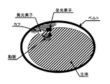
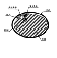
- a photoelectric sensor is disposed between the cuff for arterial compression and the living body immediately above the artery as shown in FIG. 13A or on the side in contact with the living body in the cuff as shown in FIG.
- a general method is to detect arterial volume fluctuations accompanying changes. Thick line arrows in FIGS. 13A and 13B represent the optical axis.
- Patent Document 1 Japanese Laid-Open Patent Publication No. 6-311972 discloses an example of a blood pressure information measuring apparatus using a photoelectric sensor.
- the blood pressure information measuring device disclosed in Patent Literature 1 covers a pressurizing body having a hemispherical tip, a photoelectric sensor embedded in the surface of the tip of the pressurizing body, and the photoelectric sensor.
- a pressure bag attached to the tip of the pressure body.
- a predetermined volume of fluid such as air or liquid is sealed in the pressure bag in advance.
- the tip of the pressurizing body is pressed toward the measurement site at the time of measurement, and the pressure bag is compressed by the pressurization body and the measurement site, and the photoelectric is measured.
- the volume pulse wave is measured using a sensor. JP-A-6-311972
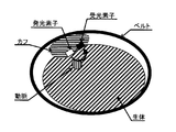
- the photoelectric sensor is tilted or the position is changed as shown in FIGS.
- the positional relationship between the sensor and the photoelectric sensor changes.
- the positional relationship between the optical axis and the artery changes as indicated by the thick arrows in FIGS. 14A and 14B.
- the photoelectric sensor may not always detect information on the same position of the artery.
- the photoelectric sensor when the photoelectric sensor is disposed between the arterial pressure cuff and the living body as shown in FIG. 13A, the force with which the arterial pressure cuff compresses the artery may be inhibited by the photoelectric sensor. Therefore, there is a problem that a correct blood pressure value cannot be measured.
- This invention is made in view of such a problem, Comprising: As a specific example, it is a blood-pressure information measuring apparatus which acquires blood-pressure information with the optical method which can mention a photoelectric sensor, Comprising: It improves measurement accuracy. Objective.
- a blood pressure information measuring device includes a compression fluid bag for compressing an artery included in a measurement site by compressing the measurement site, It includes a light projecting unit and a first light receiving unit, and emits detection light having a first wavelength that is easy to transmit through the living tissue from the first light projecting unit toward the measured site and transmits the measured site.
- a first photoelectric sensor that receives the detected light at the first light receiving unit and outputs a first output signal corresponding to the amount of the received detection light, a second light projecting unit, and a second light receiving unit, (2) Detection that is reflected from the surface of the measurement site while irradiating detection light of the second wavelength, which is shorter than the first wavelength and difficult to transmit through the living tissue, from the light projecting unit to the measurement site The light is received by the second light receiving unit, and the amount is reduced according to the amount of detected light received.
- the second photoelectric sensor that outputs one or more second output signals, and the first photoelectric sensor and the second photoelectric sensor with respect to the measurement site as in the measurement site through the compression fluid bag.
- the drive unit for causing the first light projecting unit and the second light projecting unit to emit light Calculation for calculating arterial volume pulse wave using detection unit for detecting variation in received light amount at light receiving unit, variation in received light amount at first light receiving unit, and variation in received light amount at second light receiving unit A part.
- ADVANTAGE OF THE INVENTION it can be set as the blood pressure information measurement apparatus which can acquire a volume pulse wave easily and with high precision, and a test subject's health is acquired by acquiring a volume pulse wave using the said blood pressure information measurement apparatus. Blood pressure information useful for management can be obtained with high accuracy.
- the following embodiment of the present invention employs a predetermined portion of the wrist as a measurement site, and is configured to be able to noninvasively measure the volume pulse wave of the radial artery extending into the wrist.
- the case where this invention is applied to a blood-pressure information measuring apparatus is shown.
- the part to be measured is not limited to the wrist, but may be another part such as an ankle or thigh.
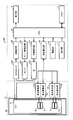
- FIG. 1 is a functional block diagram showing a configuration of a blood pressure information measurement device (hereinafter referred to as a sphygmomanometer) according to an embodiment of the present invention.
- a sphygmomanometer a blood pressure information measurement device
- the blood pressure monitor 100 includes a main body, a cuff 81 that is a measurement air bag, and a pulse wave detection unit, and the main body and the cuff 81 are connected by an air tube 10.
- an operation unit 3 including a switch and a display 4 for displaying a measurement result and the like are arranged on the front surface of the main body.
- the pulse wave detection unit includes a cuff 81, a sensor fixing unit 90, light emission drive units 120 and 20, and light reception detection units 130 and 30, and the light emission drive units 120 and 20 and the light reception detection units 130 and 30 respectively.
- the light emitting elements 121 and 21 and the light receiving elements 131 and 31 disposed in the cuff 81 are connected.
- a sensor fixing portion 90 In the cuff 81, a sensor fixing portion 90, light emitting elements 121 and 21, and light receiving elements 131 and 31 are arranged.
- the sensor fixing unit 90 fixes the positions of the light emitting element 21 and the light receiving element 31 with respect to the measurement site when the cuff 81 is wound around the wrist that is the measurement site and blood pressure is measured.
- the cuff 81 is connected to a pressure sensor 223 that measures a change in internal pressure, a pump 221 that supplies and exhausts air to the cuff 81, and a valve 222.
- the pressure sensor 223, the pump 221, and the valve 222 are connected to the oscillation circuit 28, the pump drive circuit 26, and the valve drive circuit 27, respectively. Further, the oscillation circuit 28, the pump drive circuit 26, and the valve drive circuit 27 are Each is connected to a CPU (Central Processing Unit) 40 that controls the entire blood pressure monitor 100.
- the cuff 81 may be in a state in which air, which is a predetermined amount of fluid, is sealed in advance, or may be in a state in which air is completely exhausted.
- the display 4 Further connected to the CPU 40 are the display 4, the operation unit 3, a memory 6 that stores programs executed by the CPU 40, measurement results, and the like, a pulse wave calculation unit 52, and a power source 53.
- the CPU 40 is driven by receiving power supply from the power source 53.
- the CPU 40 executes a predetermined program stored in the memory 6 based on the operation signal input from the operation unit 3, and outputs a control signal to the pump drive circuit 26 and the valve drive circuit 27.
- the pump drive circuit 26 and the valve drive circuit 27 drive the pump 221 and the valve 222 according to the control signal.
- the pump 221 is driven by a pump drive circuit 26 according to a control signal from the CPU 40 and injects air into the cuff 81.
- the valve 222 is controlled to be opened and closed by a valve drive circuit 27 according to a control signal from the CPU 40, and the air in the cuff 81 is discharged.
- the pressure sensor 223 detects a change in the internal pressure of the cuff 81 and inputs a detection signal to the oscillation circuit 28. A signal having an oscillation frequency corresponding to the input detection signal is generated and input to the CPU 40.
- the CPU 40 executes a predetermined program stored in the memory 6 based on the operation signal input from the operation unit 3, and outputs a control signal to the pulse wave calculation unit 52. Furthermore, the pulse wave calculation unit 52 outputs a control signal to the light emission drive units 120 and 20 and the light reception detection units 130 and 30 according to the control signal.
- the light emitting element 21 and the light receiving element 31 constitute a volume pulse wave measurement photoelectric sensor, and are arranged at a position sandwiching the artery when the cuff 81 is wound around the measurement site.
- the light emitting element 121 and the light receiving element 131 constitute a living body-sensor distance measuring photoelectric sensor, and are arranged on the same plane as the light emitting element 21 and the light receiving element 31 which are volumetric pulse wave measuring photoelectric sensors.
- the light emission drive unit 120 and the light emission drive unit 20 apply a current to the light emitting element 121 and the light emitting element 21, respectively, according to the control signal.
- the current applied to the light emitting element 121 and the light emitting element 21 is a direct current of about 50 mA at which the light emission output of the light emitting element to be used is maximized.
- the current applied to the light emitting element 121 and the light emitting element 21 may be a pulse current having a constant duty, for example. Thereby, the average applied power to the light emitting element can be suppressed, that is, there is an effect of preventing a temperature rise.
- the pulse frequency is preferably a frequency sufficiently higher than a frequency component of about 30 Hz included in the detected pulse wave, for example, about 100 times 3 kHz.
- the light emitting element 121 an element that emits light having a short wavelength, which is a wavelength that hardly penetrates a living tissue, is used.
- the light emitting element 121 emits light in a short wavelength region near 450 nm.
- an element that emits a long wavelength, which is a wavelength that is easily transmitted through a living tissue is used.
- the light emitting element 21 emits light in a high wavelength region near 940 nm.
- the light receiving element 131 an element that receives a short wavelength, which is a wavelength that is difficult to transmit through living tissue, is used.
- the light receiving element 131 receives light in a short wavelength region near 450 nm.
- an element that receives a long wavelength, which is a wavelength that is easily transmitted through a living tissue is used.
- the light receiving element 31 receives light in a high wavelength region near 940 nm.
- the light receiving element 31 receives light emitted from the light emitting element 21 and transmitted through the artery.
- Each of the light receiving element 131 and the light receiving element 31 outputs a voltage signal corresponding to the amount of received light to the light receiving detection unit 130 and the light receiving detection unit 30.
- a filter that blocks (cuts) transmission of light having a specific wavelength (for example, about 800 nm) or less is disposed on the surface of the cuff 81 that contacts the non-measurement site. Thereby, the light irradiated from the light emitting element 121 can be more difficult to transmit through the living body.
- the light reception detection unit 130 and the light reception detection unit 30 detect the amount of light received by the light receiving element 131 and the amount of light received by the light receiving element 31, respectively, according to the control signal from the pulse wave calculation unit 52. Each detected light amount is input to the pulse wave calculation unit 52, and the pulse wave calculation unit 52 calculates a pulse wave using these light amounts.
- the pulse wave calculation unit 52 inputs a volume pulse wave signal indicating the calculated pulse wave to the CPU 40.
- the light emitting element 21 and the light receiving element 31, which are volumetric pulse wave measuring photoelectric sensors, and the light emitting element 121 and the light receiving element 131, which are biosensor-sensor distance measuring photoelectric sensors, are also used in the same sensor.
- the light receiving element 31 and the light receiving element 131 may be configured by one light receiving element having a wide detection wavelength. At this time, the light emitting elements 31 and 131 having different wavelengths are turned on at different timings, and two wavelength signals are detected by processing the received light signals corresponding to the lighting timings of the respective light emitting elements.
- the CPU 40 executes predetermined processing based on the pressure signal, and outputs the control signal to the pump drive circuit 26 and the valve drive circuit 27 according to the result. Further, the CPU 40 applies a predetermined algorithm to the volume pulse wave signal and the pressure signal to determine the systolic blood pressure and the diastolic blood pressure, and performs processing for displaying the measurement result on the display 4 to display the data. And the control signal are output to the display 4. Further, the CPU 40 performs a process for storing the blood pressure value as a measurement result in the memory 6.
- FIG. 2A is a schematic cross-sectional view showing a state in which the pulse wave detection unit according to the present embodiment is worn on the wrist.
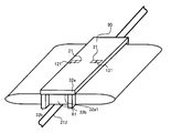
- FIG. 3A is a schematic perspective view showing the configuration of the pulse wave detector shown in FIG. 2A.
- a radial artery (hereinafter referred to as an artery) 212 is located as a characteristic biological tissue inside a wrist 200 that is a measurement site.
- the cuff 81 as the pulse wave detection unit is attached in a state of being wound around the wrist 200.
- the cuff 81 is configured in a shape suitable for wearing on the subject's wrist 200, and the sensor fixing portion 90 is arranged as described above.
- the sensor fixing portion 90 is connected to the belt member 32.
- the belt member 32 is formed of a belt-like member having a length that can be wound around the wrist 200, and is a hook-and-loop fastener (not shown) provided at a portion near one end and a portion near the other end in the longitudinal direction. Is engaged in a state of being wound around the wrist 200.
- the sensor fixing portion 90 has a base portion 32a attached to the belt member 32 and a guide portion 32b erected from an end portion of the base portion 32a.
- the base 32 a has a rectangular plate shape in plan view, and is attached to the belt member such that the longitudinal direction intersects (substantially orthogonal) the longitudinal direction of the belt member 32.
- the volume pulse wave measuring photoelectric sensor composed of the light emitting element 21 and the light receiving element 31, and the living body-sensor distance measuring photoelectric sensor composed of the light emitting element 121 and the light receiving element 131 are attached.
- the guide portion 32b protrudes from the base portion 32a toward the sensor attachment surface 32a1 (toward the measurement site side in the mounted state).
- the guide portion 32b is erected from a pair of opposite sides of the base portion 32a, and has a wall shape.
- the sensor fixing portion 90 is connected to the belt member 32 by adhesion, welding, screwing, or the like.
- the volume pulse wave measurement photoelectric sensor composed of the light emitting element 21 and the light receiving element 31, and the biosensor-measurement distance photoelectric sensor composed of the light emitting element 121 and the light receiving element 131 are arranged in the longitudinal direction of the sensor mounting surface 32a1 of the sensor fixing portion 90. It is arrange
- the distance between the light emitting element 21 and the light receiving element 31 that are spaced apart is such that the detection light can be stably radiated to the artery 212 located under the skin, and the detection light is transmitted or reflected within the measurement site.
- the distance from the sensor mounting surface 32a1 to the measurement site ie, the height of the guide portion 32b
- the distance from the sensor mounting surface 32a1 to the measurement site ie, the height of the guide portion 32b
- the light emitting element 121 and the light receiving element 131 are disposed very close to the light emitting element 21 and the light receiving element 31, respectively. Ideally, since they are arranged at the same position, preferably, as shown in FIG. 2A and FIG. 3A, for example, both elements are arranged in the same chip. It is arranged at the position.
- the sensor fixing portion 90 is disposed at a position surrounding the cuff 81 with respect to the cuff 81 so that the cuff 81 is positioned on the sensor mounting surface 32a1 of the base portion 32a.
- the cuff 81 is disposed so as to fill a space constituted by the base portion 32 a and the guide portion 32 b of the sensor fixing portion 90, and the light emitting elements 121, 21 and the light receiving elements 131, 31 are arranged by the cuff 81. It is completely covered.
- the sensor fixing unit 90 does not necessarily have to be disposed at a position surrounding the cuff 81 with respect to the cuff 81.
- the positions of the light emitting elements 121 and 21 and the light receiving elements 131 and 31 are determined based on the body to be measured. What is necessary is just to be arrange
- the cuff 81 is formed of a material capable of transmitting the detection light emitted from the light emitting elements 121 and 21, and most of the detection light emitted from the light emitting elements 121 and 21 is transmitted through the cuff 81. Then, the light is projected onto the measurement site.
- the pair of wall-shaped guide portions 32b are provided so as to surround the light emitting elements 121 and 21 and the light receiving elements 131 and 31 when the sensor mounting surface 32a1 is viewed from the normal direction.
- the cuff 81 is also surrounded by a pair of wall-shaped guide portions 32b. Note that the main surface of the exposed surface of the cuff 81 that is positioned substantially parallel to the sensor mounting surface 32a1 is a compression acting surface 81a that lightly compresses the artery 212 by lightly compressing a predetermined portion of the wrist 200 as a measurement site. Function as.
- the sensor fixing unit 90 comes into contact with the skin immediately above the portion where the artery 212 is located (more specifically, the compression acting surface 81a of the cuff 81). In this state, it is positioned and arranged. This positioning is performed by adjusting the attachment position of the belt member 32 with respect to the circumferential direction of the wrist 200. At this time, as shown in FIG. 3A, the center position of the sensor fixing unit 90 in the short direction is arranged immediately above the artery 212 that runs in the wrist 200.
- the light emitting elements 121 and 21 and the light receiving unit are arranged so as to sandwich the artery 212 in a direction intersecting with the extending direction of the artery 212 when the body surface is viewed from the normal direction.
- Elements 131 and 31 are arranged.
- the part where the artery 212 is located is specified by palpation or the like.
- the belt member 32 is fixed using a hook-and-loop fastener (not shown) to realize the mounting state shown in FIG. 2A.
- the pulse wave detection unit is fixed in a state of being pressed toward the wrist 200.
- the tip of the guide portion 32b of the sensor fixing portion 90 is addressed to the body surface in the vicinity of the measurement site in the mounted state, whereby the light emitting element 21 and the light receiving element 31 provided in the pulse wave detection portion.
- the relative positional relationship between the arterial 212 and the photoelectric sensor for measuring the volume pulse wave, the photoelectric sensor for measuring the distance between the living body and the sensor composed of the light emitting element 121 and the light receiving element 131 is maintained.
- the sensor fixing unit 90 is not fixed to the belt member 32, and may be configured separately from the belt member 32.
- the belt member 32 is wound from the outer periphery in a state where the sensor fixing portion 90 is pressed against the non-measurement portion, and the sensor fixing portion 90 is fixed to the non-measurement portion, so that the mounting state shown in FIG. Realized.
- FIG. 4 is a schematic cross-sectional view showing a usage state of the pulse wave detector in the present embodiment.
- the pressure acting surface 81 a of the cuff 81 protrudes from the sensor fixing portion 90 and the measurement site is lightly compressed, Along with this, the artery 212 is also lightly compressed.
- the sensor fixing portion 90 is held in a state of being pressed toward the measurement site by the belt member 32, and the tip of the guide portion 32b of the sensor fixing portion 90 is measured even in the compressed state.
- the state of contact with the skin in the vicinity of the site is maintained, and the relative positional relationship between the arterial 212 and the plethysmogram photoelectric sensor composed of the light emitting element 21 and the light receiving element 31 is also maintained.
- the light emitting element 121 Similarly, light of a low wavelength region of 450 nm is emitted from the light emitting element 121 toward the body surface of the measurement site, and the light reflected by the body surface is received by the light receiving element 131.
- the amount of light reflected on the body surface varies in proportion to the distance between the living body and the sensor (hereinafter, the distance between the living body and the sensor).
- the light reception detection unit 130 optically captures and detects a variation in the distance between the living body and the sensor.
- the guide portion 32b is erected from the base portion 32a of the sensor fixing portion 90 to which the plethysmogram measuring photoelectric sensor composed of the light emitting element 21 and the light receiving element 31 is attached.
- the tip of the guide portion 32b is configured to be directed to the body surface in the vicinity of the measurement site. Accordingly, the relative positional relationship between the volume pulse wave measurement photoelectric sensor and the artery 212 is always maintained during the measurement operation, and the direction of the photoelectric sensor is deviated from the radial artery, which has been a problem in the past. The problem of end up does not occur.
- FIG. 5 is a flowchart showing a specific example of processing executed at a timing when power is supplied from the power source 53 to the CPU 40 when a power switch (not shown) of the operation unit 3 is operated in the sphygmomanometer 100.
- the processing shown in the flowchart of FIG. 5 is realized by the CPU 40 executing a predetermined program stored in the memory 6.
- CPU 40 initializes a processing memory area (not shown) of CPU 40, exhausts the air in cuff 81, and pressure sensor 223. 0 mmHg correction is performed (ST2).
- the CPU 40 pressurizes the cuff 81 to a predetermined pressure that is about the maximum blood pressure of the person to be measured + 40 mmHg. (ST4) Then, the pressure in the cuff 81 is gradually reduced (ST5).
- the CPU 40 acquires the pressure in the cuff 81 from the pressure sensor 223 during decompression. Further, the calculated volume pulse wave of the artery is acquired from the pulse wave calculation unit 52. And CPU40 calculates blood pressure using them (ST6, ST7), and displays on the indicator 4 (ST8).
- the living body-sensor distance d1 shown in FIG. 2A before the cuff 81 is pressurized changes as shown by the distance d2 in FIG. To do. That is, the living body-sensor distance varies as the cuff 81 is pressurized and expanded.
- the variation in the distance between the living body and the sensor is detected by being superimposed on the volume variation of the artery. That is, the light reception detection unit 30 detects the arterial volume fluctuation including the fluctuation of the living body-sensor distance.
- variation in the distance between the living body and the sensor may affect the blood pressure value calculated in step ST6. Therefore, the sphygmomanometer 100 according to the present embodiment executes the following process in step ST6.
- FIG. 6 is a flowchart showing a specific example of the pulse wave measurement process in step ST6.
- a constant current e.g., 50 mA
- a control signal from CPU 40 whereby light in a high wavelength region is emitted from light emitting element 21.
- the artery 212 is irradiated.
- step S ⁇ b> 103 the amount of light Eh emitted from the light emitting element 21 by the light receiving element 31 and transmitted through the artery 212, i.e., the arterial volume, is detected and converted into a voltage by the light receiving detector 30.
- the CPU 40 stops the light emission driving unit 20.
- step S107 a constant current (for example, 50 mA) is applied from the light emission drive unit 120 to the light emitting element 121 in accordance with a control signal from the CPU 40, so that light in the low wavelength region from the light emitting element 121 is transmitted to the measurement site. Irradiated to the body surface.
- step S109 the light amount El reflected from the light emitting element 121 by the light receiving element 131 and reflected from the body surface, that is, the distance between the living body and the sensor is detected, and is converted into a voltage by the light receiving detector 130.
- step S111 the CPU 40 stops the light emission driving unit 120.
- step S113 the pulse wave calculation unit 52 uses the arterial volume information detected by the light reception detection unit 30 in step S103 and the bio-sensor distance information detected by the light reception detection unit 130 in S109. Using this, the arterial volume fluctuation in which the influence of the living body-sensor distance fluctuation is reduced, ie, the volume pulse wave in which the influence of the living body-sensor distance fluctuation is reduced is calculated.
- the pulse wave calculation unit 52 includes the arterial volume information detected by the light reception detection unit 30 in step S103 and the bio-sensor distance information detected by the light reception detection unit 130 in S109. Is used to calculate the arterial volume fluctuation from which the influence of the living body-sensor distance fluctuation is removed, that is, the volume pulse wave from which the influence of the living body-sensor distance fluctuation is removed.
- step S101 to S103 are repeated until the CPU 40 determines that the measurement is complete.
- the pulse wave measurement process in step ST6 ends.
- the pulse wave calculation unit 52 stores sensor characteristics for each sensor in advance.
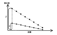
- the sensor characteristic for example, the relationship between the detection value in the light reception detection unit 30 and the detection value in the light reception detection unit 130 as shown in FIG.
- the relationship shown in FIG. 7 is that, for example, light is emitted from the light emitting element 21 and the light emitting element 121 to a substance that does not transmit light in either the high wavelength region or the low wavelength region, and the light emitting element and the material to be irradiated with light.
- the light reception detection unit 30 and the light reception detection unit 130 detect the amount of light while changing the distance between them. That is, the above relationship can be said to be the relationship between the change rate of the detection value with respect to the change in the distance from the light emitting element to the irradiation target in the light reception detection unit 30 and the light reception detection unit 130.
- the pulse wave calculation unit 52 has the rate of change of the detection value with respect to the change in the distance from the light emitting element to the irradiation target as the sensor characteristics for each sensor. It is assumed that ⁇ : ⁇ is stored as a value.
- the detection value of the detection value of the light reception detection unit 30 and the detection value of the light reception detection unit 130 and the ratio of the change rate of the detection value with respect to the change in the distance from the light emitting element to the irradiation target are indicated by ⁇ : ⁇ in the above description It is not limited to such a fixed ratio. Therefore, in the above example, the ratio between the detection value of the light reception detection unit 30 and the detection value of the light reception detection unit 130 of the change rate of the detection value with respect to the change in the distance from the light emitting element to the irradiation target is stored as ⁇ : ⁇ .
- the detection value of the light reception detection unit 30 and the detection value of the light reception detection unit 130 according to the distance from the light emitting element to the irradiation target may be stored in a table format, for example. Good.
- the pulse wave calculation unit 52 obtains the detection value of the light reception detection unit 130 from the detection value of the light reception detection unit 30 with reference to the table, and calculates the arterial volume fluctuation W using these detection values. .
- the pulse wave calculation unit 52 in step S113 By performing the above calculation by the pulse wave calculation unit 52 in step S113, the arterial volume variation obtained from the arterial volume information detected by the light reception detection unit 30 in step S103 using the sensor characteristics.
- the arterial volume fluctuation W is obtained by reducing (removing) the influence of the biological-sensor distance fluctuation obtained from the biological-sensor distance information detected by the light receiving detector 130 in S109. Therefore, the configuration as shown in FIG. 2A and FIG. 2B does not cause the problem that the direction of the photoelectric sensor deviates from the artery which has been a problem in the past, and the above-described problem occurs.
- By performing the calculation even when the distance between the living body and the sensor changes as shown in FIG.
- step ST7 the change in the cuff pressure during pressure reduction in step ST5 (or pressure in step ST4) is measured to measure the arterial state of the artery.
- the blood pressure is calculated by detecting the volume fluctuation.
- the blood pressure can also be calculated using arterial volume variation from which the influence due to variation in the distance between the living body and the sensor is removed when the pulse wave is detected in step S113.
- the blood pressure calculation of the volume compensation method it is possible to use arterial volume fluctuation in which the influence due to fluctuation in the distance between the living body and the sensor is removed when the pulse wave is detected in step S113. By doing in this way, the measurement accuracy of blood pressure can be improved.
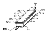
- the pulse wave detection unit of the sphygmomanometer 100 includes a volume pulse wave measurement photoelectric sensor composed of a pair of light emitting elements 21 and a light receiving element 31, and a living body-sensor composed of a pair of light emitting elements 121 and a light receiving element 131. And a photoelectric sensor for distance measurement. Furthermore, as a modification, for example, as shown in FIG. 8, a plurality of pairs of biological sensors for measuring the distance between the living body and the sensor may be included.
- the volume pulse wave measurement photoelectric sensor composed of a pair of the light emitting element 21 and the light receiving element 31 is sandwiched between the light emitting element 21 and the light receiving element 31 at equal intervals.
- a photoelectric sensor for measuring the distance between sensors is arranged.
- the arrangement of a plurality of pairs of living body-sensor distance measuring photoelectric sensors is not limited to the arrangement shown in FIG. 8, and may be another arrangement as shown in FIG. 9 or FIG.
- the volume pulse wave measurement photoelectric sensor is disposed at equal intervals from the light receiving element 31 with the volume pulse wave measurement photoelectric sensor including the pair of light emitting elements 21 and light receiving elements 31 interposed therebetween. Orthogonally to the first biosensor-sensor distance measurement photoelectric sensor composed of a pair of light-emitting elements 121a and light-receiving elements 131a, and a second bio-sensor distance measurement composed of a pair of light-emitting elements 121b and light-receiving elements 131b.
- a third bioelectric sensor for measuring a distance between a living body and a sensor which is composed of a pair of a light emitting element 121c and a light receiving element 131c, at equal intervals from the light emitting element 21 and the light emitting element 21, and perpendicular to the volume pulse wave measuring photoelectric sensor.
- a sensor and a fourth biosensor for measuring the distance between the living body and the sensor which is composed of a pair of light emitting element 121d and light receiving element 131d, are arranged.
- the volume pulse wave measurement photoelectric sensor composed of a pair of the light emitting element 21 and the light receiving element 31 is sandwiched between the sensor mounting surface 32 a 1 parallel to the light emitting element 21 and the light receiving element 31, respectively.
- a photoelectric sensor is arranged.
- the light emitting element 121a and the light receiving element 131a are parallel to the light emitting element 21 and the light receiving element 31, and their directions are arranged in reverse.
- FIG. 11 shows a first specific example of the pulse wave measurement process in step ST6 in the sphygmomanometer 100 according to the modification example when a plurality of pairs of living body-sensor distance measuring photoelectric sensors are included. It is a flowchart to show. Here, it is assumed that a photoelectric sensor for measuring the distance between the living body and the sensor is specifically included as shown in FIG.
- each of the first living body-sensor distance measuring photoelectric sensor and the second living body-sensor distance measuring photoelectric sensor is performed in the same manner as in steps S107 to S111.
- the light of the low wavelength region is irradiated from the light emitting elements 121a and 121b onto the body surface of the measurement site (steps S107 ′ and S107 ′′), and the light amounts Ela and Elb reflected on the body surface are detected to detect the light reception. 130 is converted into a voltage (steps S109 ′ and S109 ′′). Thereafter, irradiation of light in the low wavelength region is stopped in steps S111 'and S111 ".
- step S201 the pulse wave calculation unit 52 calculates bio-sensor distance information by calculating an average value of the light amount Ela detected in step S109 ′ and the light amount Elb detected in step S109 ′′, and in step S203. If it is determined in step S203 that the bio-sensor distance information is outside the threshold value range (NO in step S203) In step S205, the pulse wave calculation unit 52 outputs an output error to the CPU 40 and terminates the process, that is, the first biosensor-sensor distance measurement photoelectric sensor and the second biosensor-sensor distance measurement. If the distance of the photoelectric sensor to the non-measurement site is more than allowable, the process ends without performing the subsequent processes.
- step S203 If it is determined in step S203 that the bio-sensor distance information is within the threshold value range (YES in step S203), the above process is repeated until the CPU 40 determines that the measurement is completed, and the CPU 40 performs measurement. When completion is determined (YES in step S115), the pulse wave measurement process in step ST6 ends.
- step S203 when it is determined in step S203 that the average value calculated in step S201 is within a preset threshold value. Then, the pulse wave calculation unit 52 uses the average value to perform the process for obtaining the arterial volume fluctuation in step S113 in which the influence of the living body-sensor distance fluctuation is reduced.
- the sphygmomanometer 100 includes a pulse wave detection unit configured as shown in FIG. 8, and the above processing is performed, so that the distance from the sensor fixing unit 90, that is, the non-measurement part of the sensor is within an allowable range. If so, the arterial volume variation is calculated. Furthermore, more accurate biological-sensor distance information can be detected by using an average of a plurality of detection values detected by a plurality of pairs of biological-sensor distance measuring photoelectric sensors. Thereby, the detection accuracy of the pulse wave can be further improved.
- FIG. 12 shows a second specific example of the pulse wave measurement process in step ST6 in the sphygmomanometer 100 according to the modification example when a plurality of pairs of living body-sensor distance measuring photoelectric sensors are included. It is a flowchart to show. Also here, it is assumed that a photoelectric sensor for measuring the distance between the living body and the sensor is specifically included as shown in FIG.
- step S201 ′ Compares the detection values of the first photoelectric sensor for measuring the distance between the living body and the sensor and the second photoelectric sensor for measuring the distance between the living body and the sensor.
- the inclination relationship between the side where the first living body-sensor distance measuring photoelectric sensor is arranged and the side where the second living body-sensor distance measuring photoelectric sensor is arranged is detected with respect to the arrangement position of 31.
- the pulse wave calculation unit 52 is a threshold value range in which the calculated inclination index is preset in step S203 ′.
- the pulse wave is calculated in step S205 ′.
- the unit 52 outputs a signal to that effect to the CPU 40, whereby the CPU 40 performs processing for displaying a message on the display 4 so as to correct the wearing state of the cuff 81.
- step S203 ′ If it is determined in step S203 ′ that the slope index is within the threshold range (YES in step S203 ′), the above process is repeated until the CPU 40 determines that the measurement is complete, and the CPU 40 completes the measurement. If determined (YES in step S115), the pulse wave measurement process in step ST6 is terminated.
- the sphygmomanometer 100 includes a pulse wave detection unit configured as shown in FIG. 8, and the above processing is performed, so that the sensor fixing unit 90, that is, the inclination of the sensor with respect to the measurement site is made constant. It is effective in keeping.
- step S203 ′ in the determination in step S203 ′, it is determined that the slope index calculated in step S201 ′ is within a preset threshold value.
- the pulse wave calculation unit 52 performs the process for obtaining the arterial volume fluctuation that eliminates the influence of the living body-sensor distance fluctuation in step S113 described above. By doing so, the arterial volume variation is calculated using the detection value when the inclination of the sensor fixing unit 90 with respect to the measurement site is kept constant, so that the measurement accuracy can be improved.
- the processing shown in FIG. 11 and the processing shown in FIG. 12 may be combined. That is, even if it is determined in step S203 ′ that the inclination index of the sensor fixing unit 90 is out of the threshold value range and an allowable inclination has occurred, As described above, when the average value of the light amount Ela detected in step S109 ′ and the light amount Elb detected in S109 ′′ is within the threshold value, the pulse wave calculation unit 52 uses the average value to The processing for obtaining the arterial volume fluctuation in which the influence of the living body-sensor distance fluctuation in step S113 is reduced may be performed in this way, without impairing the convenience of the measurer. Measurement accuracy can be improved.
Abstract
血圧情報測定装置は、生体組織を透過し易い波長である長波長を発光する発光素子(21)および受光する受光素子(31)からなる光電センサと、透過し難い波長である短波長を発光する発光素子(121)および受光する受光素子(131)からなる光電センサとを同一平面上に備えて、長波長用の受光素子での受光量より動脈(212)を透過する光量変動が検出されて脈波が検出される。短波長用の受光素子での受光量より、カフ(81)の圧力が変動することによる生体-センサ間の動的な距離変動が検出される。そして、長波長用の受光素子での受光量より検出された脈波から、短波長用の受光素子での受光量より検出された生体-センサ間の動的な距離変動の影響を排する演算が実行される。
Description
この発明は血圧情報測定装置に関し、特に、光学的な手法により血圧情報を取得する血圧情報測定装置に関する。
被験者の血圧情報を取得することは、被験者の健康状態を知る上で非常に重要である。近年では、従来から健康管理の代表的な指標として広くその有用性が認められている収縮期血圧値および拡張期血圧値等を取得することに限られず、被験者の脈波を取得することによって心臓負荷や動脈の硬さの変化を捉える試み等がなされている。血圧情報測定装置は、取得した血圧情報に基づいてこれら健康管理のための指標を得る。血圧情報測定装置は、循環器系の疾患の早期発見や予防や治療等の分野において、さらなる活用が期待されている。なお、血圧情報には、収縮期血圧値、拡張期血圧値、平均血圧値、脈波、脈拍、AI(Augmentation Index)値等、循環器系の種々の情報が広く含まれる。
上記血圧情報の1つである脈波には、捉える対象の違いから圧脈波と容積脈波とが存在する。圧脈波は、心臓の拍動に伴う血管内圧の変動として脈波を捉えている。容積脈波は、心臓の拍動に伴う血管内容積の変動として脈波を捉えている。血管内容積の変動は、血管内圧の変動に伴って生じる現象であるため、これら圧脈波と容積脈波とは、医学的にはほぼ同様の意義をもった指標と言える。なお、血管内容積の変動は、血管内の血液組織量変動として捉えることが可能である。
以降の説明において使用する「血圧情報測定装置」という用語は、脈波を取得する機能を少なくとも有する装置全般を指す。より特定的には、光学的な手法により血液組織量変動を検出して容積脈波を取得する装置を指す。その意味において、血圧情報測定装置は、取得された容積脈波をそのまま測定結果として出力するものに限られず、取得された容積脈波に基づいて特定の他の指標を算出したり計測したり等することによって得られた他の指標のみを測定結果として出力する装置や、得られた他の指標と取得した容積脈波とを測定結果としてともに出力する装置をも含む。上述の他の指標としては、収縮期血圧値(最高血圧値)、拡張期血圧値(最低血圧値)、平均血圧値、脈拍、およびAI値等が含まれる。
なお、容積脈波は、心臓の拍動に伴う周期的な血管内容積の変動を波動として示す脈波である。この意味において、以降の説明においては、少なくとも時間差をもって血管内容積の変動が観測されれば、その時間的な分解能によらずその変動を容積脈波と称する。なお、一拍中に含まれる容積脈波を精緻に捉えるためには、当然に時間的な分解能が高いことが必要である。
一般に、被験者に苦痛を与えることなく非侵襲に容積脈波を取得することが可能な血圧情報測定装置としては、測定方式の違いに基づいて以下の3つに分類される。
第1の測定方式に基づく血圧情報測定装置は、超音波センサを具備し、この超音波センサを用いて動脈を含む生体組織に超音波を印加してその反射波を検出することによって動脈内容積変動を捉え、これに基づいて動脈の容積脈波を取得する。
第2の測定方式に基づく血圧情報測定装置は、生体インピーダンス測定装置を具備し、動脈を含む生体組織に微弱電流を印加して生体インピーダンスを測定することによって動脈内容積変動を捉え、これに基づいて動脈の容積脈波を取得する。
第3の測定方式に基づく血圧情報測定装置は、光学的な手法で血液組織量変動を捉え、これに基づいて動脈の容積脈波を取得する。
従来、光学的な手法として、発光素子および受光素子を含む光電センサを具備し、発光素子から出射された光を動脈を含む生体組織に照射し、照射された光の透過光を受光素子にて検出することによって血液組織量変動を捉え、これに基づいて動脈の容積脈波を取得する血圧情報測定装置がある。この血圧情報測定装置では、図13Aのように動脈圧迫用カフと動脈直上の生体との間、または図13Bのようなカフ内で生体に接触する側に光電センサを配置し、カフ内圧力の変化に伴う動脈の容積変動を検出する方法が一般的である。図13Aおよび図13B中の太線の矢印は、光軸を表わしている。
特開平6-311972号公報(以下、特許文献1)は、光電センサを利用した血圧情報測定装置の一例を開示している。特許文献1に開示の血圧情報測定装置は、先端部が半球形状に形成された加圧体と、当該加圧体の先端部の表面に埋設された光電センサと、当該光電センサを覆うように加圧体の先端部に取付けられた加圧バッグとを備えている。加圧バッグには、所定容量の空気または液体等の流体が予め封入されている。そして、当該血圧情報測定装置においては、測定に際して加圧体の先端部を被測定部位に向けて押圧し、加圧体と被測定部位とによって加圧バッグが圧縮された状態を維持して光電センサを用いて容積脈波の測定が行なわれる。
特開平6-311972号公報
しかしながら、血圧情報測定のため、カフ内圧力を変化させた場合、カフの形状変化に伴って、図14Aや図14Bのように、光電センサが傾いたり、位置が変化したりすることで、動脈と光電センサとの位置関係が変化することが多々ある。これにより、図14Aや図14Bにおいて太線の矢印で示されるように、光軸と動脈との位置関係が変化する。この場合、たとえば図14Aに示されるように、動脈が検出されなくなったり、図14Bに示されるように動脈を検出する位置が異なってしまったりする。すなわち、カフ内圧力を変化させるに伴って、光電センサが常に動脈の同じ位置の情報を検出していない場合も発生する。
さらに、図13Aのように動脈圧迫用カフと生体との間に光電センサが配置された場合、動脈圧迫用カフが動脈を圧迫する力が光電センサによって阻害される場合がある。そのため、正しい血圧値を測定できないという問題がある。
本発明はこのような問題に鑑みてなされたものであって、具体例として光電センサが挙げられる光学的な手法により血圧情報を取得する血圧情報測定装置であって、測定精度を向上させることを目的とする。
上記目的を達成するために、本発明のある局面に従うと、血圧情報測定装置は、被測定部位を圧迫することによって被測定部位に含まれる動脈を圧迫するための圧迫用流体袋と、第1投光部および第1受光部を含み、第1投光部から被測定部位に向けて、生体組織を透過し易い波長である第1の波長の検出光を照射するとともに、被測定部位を透過した検出光を第1受光部にて受光し、受光した検出光の光量に応じた第1出力信号を出力する第1の光電センサと、第2投光部および第2受光部を含み、第2投光部から被測定部位に向けて、第1の波長よりも短い、生体組織を透過し難い波長である第2の波長の検出光を照射するとともに、被測定部位の表面で反射した検出光を第2受光部にて受光し、受光した検出光の光量に応じた少なくとも1つ以上の第2出力信号を出力する第2の光電センサと、第1の光電センサおよび第2の光電センサを、圧迫用流体袋を介して被測定部位に対するように、被測定部位に対する位置を固定するための固定部と、第1投光部および第2投光部を発光させるための駆動部と、第1出力信号および第2出力信号に基づいて、第1受光部および第2受光部での受光量の変動を検出する検出部と、第1受光部での受光量の変動と、第2受光部での受光量の変動とを用いて動脈の容積脈波を算出する算出部とを備える。
本発明によれば、簡便かつ高精度に容積脈波の取得が可能な血圧情報測定装置とすることができ、当該血圧情報測定装置を利用して容積脈波を取得することにより、被験者の健康管理を図る上で有用な血圧情報を高精度に得ることが可能になる。
3 操作部、4 表示器、6 メモリ、10 エア管、20,120 発光駆動部、21,121,121a,121b,121c,121d 発光素子、22a 基部、22a1 センサ取付面、22b ガイド部、26 ポンプ駆動回路、27 弁駆動回路、28 発振回路、30,130 受光検出部、31,131,131a,131b,131c,131d 受光素子、32 ベルト部材、32a 基部、32a1 センサ取付面、32b ガイド部、40 CPU、52 脈波算出部、53 電源、81 カフ、81a 圧迫作用面、90 センサ固定部、100 血圧計、200 手首、212 動脈、221 ポンプ、222 弁、223 圧力センサ。
以下に、図面を参照しつつ、本発明の実施の形態について説明する。以下の説明では、同一の部品および構成要素には同一の符号を付してある。それらの名称および機能も同じである。なお、以下に示す本発明の実施の形態は、被測定部位として手首の所定部分を採用し、手首中に延在する橈骨動脈の容積脈波を非侵襲に測定することが可能に構成された血圧情報測定装置に本発明を適用した場合を示すものである。被測定部位は手首に限定されず、足首、大腿部等、その他の部位でもよい。
図1は、本発明の実施の形態における血圧情報測定装置(以下、血圧計)の構成を示す機能ブロック図である。
本実施の形態における血圧計100は、本体と測定用空気袋であるカフ81と脈波検出部とを備え、本体とカフ81とはエア管10で接続される。図1を参照して、本体の正面には、スイッチ等を含む操作部3と、測定結果等を表示する表示器4とが配備される。脈波検出部は、カフ81と、センサ固定部90と、発光駆動部120,20と、受光検出部130,30とを含み、発光駆動部120,20および受光検出部130,30が、各々、カフ81に配置される発光素子121,21および受光素子131,31に接続される。
カフ81には、センサ固定部90と発光素子121,21および受光素子131,31とが配置されている。センサ固定部90は、カフ81を測定部位である手首に巻付けて血圧測定する際に、測定部位に対する発光素子21および受光素子31の位置を固定する。
カフ81は、内圧変化を測定する圧力センサ223、カフ81に対する給気/排気を行なうポンプ221、および弁222に接続される。圧力センサ223、ポンプ221、および弁222は、各々、発振回路28、ポンプ駆動回路26、および弁駆動回路27に接続され、さらに、発振回路28、ポンプ駆動回路26、および弁駆動回路27は、各々、血圧計100全体を制御するCPU(Central Processing Unit)40に接続される。カフ81は、予め一定量の流体である空気が封入された状態とされていてもよいし、完全に空気が排気された状態とされていてもよい。
CPU40には、さらに、表示器4と、操作部3と、CPU40で実行されるプログラムや測定結果等を記憶するメモリ6と、脈波算出部52と、電源53とが接続される。
CPU40は、電源53から電力供給を受けて駆動する。CPU40は、操作部3から入力される操作信号に基づいてメモリ6に記憶されている所定のプログラムを実行し、ポンプ駆動回路26および弁駆動回路27に制御信号を出力する。ポンプ駆動回路26および弁駆動回路27は、制御信号に従ってポンプ221および弁222を駆動させる。ポンプ221は、CPU40からの制御信号に従ったポンプ駆動回路26によってその駆動が制御されて、カフ81内に空気を注入する。弁222は、CPU40からの制御信号に従った弁駆動回路27によってその開閉が制御されて、カフ81内の空気を排出する。
圧力センサ223はカフ81の内圧変化を検出し、検出信号を発振回路28に入力する。入力された検出信号に応じた発振周波数の信号を生成し、CPU40に入力される。
また、CPU40は、操作部3から入力される操作信号に基づいてメモリ6に記憶されている所定のプログラムを実行し、脈波算出部52に制御信号を出力する。さらに脈波算出部52は、上記制御信号に従って発光駆動部120,20および受光検出部130,30に制御信号を出力する。
発光素子21と受光素子31とは容積脈波測定用光電センサを構成し、カフ81を測定部位に巻き付けた際に動脈を挟む位置に配置される。発光素子121と受光素子131とは生体-センサ間距離測定用光電センサを構成し、容積脈波測定用光電センサである発光素子21および受光素子31と同一平面上に配置される。
発光駆動部120および発光駆動部20は、上記制御信号に従って、各々、発光素子121および発光素子21に電流を印加する。好ましくは、発光素子121および発光素子21へ印加される電流は、使用する発光素子の発光出力が最大となる電流50mA程度の直流電流である。また、発光素子121および発光素子21へ印加される電流は、たとえば一定Dutyのパルス電流とすることも可能である。これにより、発光素子への平均印加電力を抑制することができ、すなわち温度上昇を防ぐ効果がある。パルス周波数は、好ましくは、検出脈波に含まれる周波数成分30Hz程度より十分に高い周波数、たとえば100倍の3kHz程度である。
発光素子121には生体組織を透過し難い波長である短波長を発光する素子が用いられる。好ましくは、発光素子121は450nm付近の短波長領域の光を発光する。発光素子21には生体組織を透過し易い波長である長波長を発光する素子が用いられる。好ましくは、発光素子21は940nm付近の高波長領域の光を発光する。これにより、カフ81を測定部位に巻き付けた際には、発光素子121および発光素子21の各々によって、動脈直上の生体表面(皮膚)に、短波長の光および長波長の光が照射される。
受光素子131には生体組織を透過し難い波長である短波長を受光する素子が用いられる。好ましくは、受光素子131は450nm付近の短波長領域の光を受光する。受光素子31には生体組織を透過し易い波長である長波長を受光する素子が用いられる。好ましくは、受光素子31は940nm付近の高波長領域の光を受光する。これにより、カフ81を測定部位に巻き付けた際には、受光素子131は、発光素子121から発光され、動脈直上の生体表面(皮膚)で反射した光を受光する。受光素子31は、発光素子21から発光され、動脈を透過した光を受光する。受光素子131および受光素子31は、各々、受光した光量に応じた電圧信号を受光検出部130および受光検出部30に対して出力する。なお、好ましくは、カフ81の、非測定部位と接触する面には、特定波長(たとえば800nm程度)以下の光の透過を遮断(カット)するフィルタが配置される。これにより、発光素子121から照射される光が生体内をより透過し難くできる。
受光検出部130および受光検出部30は、脈波算出部52からの制御信号に従って、各々、受光素子131で受光した光量および受光素子31で受光した光量を検出する。検出された各光量は、脈波算出部52に入力され、脈波算出部52において、これら光量を用いて脈波が算出される。脈波算出部52は算出された脈波を示す容積脈波信号をCPU40に入力する。
なお、容積脈波測定用光電センサである発光素子21および受光素子31と、生体-センサ間距離測定用光電センサである発光素子121および受光素子131とを、同一のセンサで用途を兼用することも可能である。たとえば、受光素子31と受光素子131とを検出波長が広域の1つの受光素子で構成してもよい。この時、波長の異なる発光素子31,131を異なるタイミングで点灯して、各発光素子の点灯タイミングに対応した、受光信号を処理することで2つの波長信号を検出する。
CPU40は、圧力信号に基づいて所定の処理を実行し、その結果に応じてポンプ駆動回路26および弁駆動回路27に上記制御信号を出力する。また、CPU40は、容積脈波信号、および圧力信号に所定のアルゴリズムを適用して最高血圧および最低血圧を決定し、測定結果を表示器4に表示させるための処理を行なって表示させるためのデータと制御信号とを表示器4に出力する。また、CPU40は、測定結果である血圧値をメモリ6に記憶させるための処理を行なう。
図2Aは、本実施の形態における脈波検出部を手首に装着した状態を示す模式断面図である。また、図3Aは、図2Aに示す脈波検出部の構成を示す概略斜視図である。
図2Aに示すように、測定部位である手首200の内部には、特徴的な生体組織として橈骨動脈(以下、動脈)212が位置している。脈波検出部としてのカフ81は、手首200に巻き回された状態で装着される。
カフ81は、被験者の手首200への装着に適した形状に構成されており、上述のようにセンサ固定部90が配されている。
図2Aおよび図3Aに示すように、センサ固定部90は、ベルト部材32に接続されている。ベルト部材32は、手首200に巻き回すことが可能な長さを有する帯状の部材からなり、その長手方向の一方端寄りの部分と他方端寄りの部分とに設けられた面ファスナ(不図示)を係合させることによって手首200に巻き回した状態で装着される。センサ固定部90は、ベルト部材32に取付けられる基部32aと、この基部32aの端部から立設されたガイド部32bとを有している。基部32aは、平面視矩形状の板状の形状を有しており、その長手方向がベルト部材32の長尺方向と交差(略直交)するようにベルト部材に取付けられている。基部32aの一方の主面は、上述した発光素子21および受光素子31でなる容積脈波測定用光電センサ、ならびに発光素子121および受光素子131でなる生体-センサ間距離測定用光電センサが取付けられるセンサ取付面32a1である。ガイド部32bは、基部32aからセンサ取付面32a1側に向けて(装着状態において被測定部位側に向けて)突設されている。ガイド部32bは、基部32aの相対する一対の辺からそれぞれ立設されており、壁状の形状を有している。なお、センサ固定部90のベルト部材32への接続は、接着、溶着、ビス留め等によって行なわれる。
発光素子21および受光素子31でなる容積脈波測定用光電センサ、ならびに発光素子121および受光素子131でなる生体-センサ間距離測定用光電センサは、センサ固定部90のセンサ取付面32a1の長手方向の略中央部に配置されている。より具体的には、発光素子21および受光素子31は、基部32aの短手方向(すなわち、ベルト部材32の長尺方向)に所定の距離を隔てて並べて配置されている。ここで、離間配置される発光素子21および受光素子31の間の距離は、皮下に位置する動脈212にまで安定的に検出光を照射可能とし、かつ被測定部位内を透過または反射した検出光を確実に受光可能とするために、たとえばセンサ取付面32a1から被測定部位までの距離(すなわち、ガイド部32bの高さ)の2倍程度かそれ以上とすることが好ましい。仮に、この距離を短くした場合には、発光素子21から出射された検出光が皮膚の表面においてほぼ全反射してしまい、検出光が動脈212にまで達せず、正確な測定ができなくなるおそれがある。発光素子121および受光素子131は、各々、発光素子21および受光素子31のきわめて近傍に配置されている。理想的には同一位置に配置されることであるため、好ましくは、図2A、図3Aに示されるように、たとえば同一チップ内に両素子を配置するなど、ほぼ同一位置とみなされる程度の隣接した位置に配置される。
センサ固定部90は、基部32aのセンサ取付面32a1上にはカフ81が位置するよう、カフ81に対してカフ81を囲む位置で配設される。これにより、カフ81は、センサ固定部90の基部32aおよびガイド部32bによって構成される空間を充填するように配置されており、発光素子121,21および受光素子131,31は、このカフ81によって完全に覆われた状態となっている。なお、センサ固定部90は、必ずしも、カフ81に対してカフ81を囲む位置で配設されていなくてもよく、発光素子121,21および受光素子131,31の位置を、被測定部位の体表面に対して固定し得る位置に配設されていればよい。たとえば、センサ固定部90とカフ81との位置関係のその他の例としては、図3Bに示されるように、カフ81を被測定部位の体表面に対して挟む位置であってもよい。
ここで、カフ81は、発光素子121,21から出射される検出光を透過可能な材料で形成されており、発光素子121,21から出射された検出光は、その大部分がカフ81を透過して被測定部位へと投光される。
一対の壁状の形状を有するガイド部32bは、センサ取付面32a1を法線方向から見た場合に発光素子121,21および受光素子131,31を取り囲むように設けられている。また、カフ81も一対の壁状の形状を有するガイド部32bによって囲まれている。なお、カフ81の露出表面のうちのセンサ取付面32a1と略平行に位置する主面は、被測定部位としての手首200の所定部分を軽圧迫することにより動脈212を軽圧迫する圧迫作用面81aとして機能する。
図2Aに示すように、脈波検出部の装着に際して、センサ固定部90は、動脈212が位置する部分の直上の皮膚にその下面(より詳細にはカフ81の圧迫作用面81a)が当接した状態で位置決めして配置される。この位置決めは、手首200の周方向に対するベルト部材32の取付位置を調節することで行なわれる。その際、図3Aに示されるように、センサ固定部90の短手方向の中心位置が、手首200中を走行する動脈212の直上に配置されるようにする。このように脈波検出部を位置決めして配置することにより、体表面を法線方向から見た場合に動脈212の延びる方向と交差する方向に動脈212を挟み込むように発光素子121,21および受光素子131,31が配置されることになる。なお、動脈212が位置する部分の特定は触診等によって行なわれる。
上記位置決め後、ベルト部材32を面ファスナ(不図示)を用いて固定することにより、図2Aに示す装着状態が実現される。この装着状態においては、脈波検出部が手首200に向けて押し付けられた状態で固定されることになる。また、センサ固定部90のガイド部32bの先端は、当該装着状態において被測定部位近傍の体表面に宛がわれることとなり、これにより脈波検出部に設けられた発光素子21および受光素子31でなる容積脈波測定用光電センサ、ならびに発光素子121および受光素子131でなる生体-センサ間距離測定用光電センサと動脈212との相対的な位置関係が保持されるようになる。
なお、センサ固定部90は、図2Bに示されるように、ベルト部材32には固定されておらず、ベルト部材32とは別体で構成されてもよい。この場合、ベルト部材32をセンサ固定部90を非測定部位に押し付けた状態でその外周から巻付けて、センサ固定部90を非測定部位に対して固定することで、図2Bに示す装着状態が実現される。
図4は、本実施の形態における脈波検出部の使用状態を示す模式断面図である。
図4に示すように、カフ81が所定圧にまで加圧された状態においては、カフ81の圧迫作用面81aがセンサ固定部90から迫り出した状態となって被測定部位が軽圧迫され、これに伴って動脈212も軽圧迫されることになる。これは、センサ固定部90がベルト部材32によって被測定部位に向けて押圧された状態に保持されているためであり、当該圧迫状態においてもセンサ固定部90のガイド部32bの先端は、被測定部位近傍の皮膚に当接した状態に維持され、発光素子21および受光素子31でなる容積脈波測定用光電センサと動脈212との相対的な位置関係も保持されることになる。
図4に示すように、カフ81が所定圧にまで加圧された状態においては、カフ81の圧迫作用面81aがセンサ固定部90から迫り出した状態となって被測定部位が軽圧迫され、これに伴って動脈212も軽圧迫されることになる。これは、センサ固定部90がベルト部材32によって被測定部位に向けて押圧された状態に保持されているためであり、当該圧迫状態においてもセンサ固定部90のガイド部32bの先端は、被測定部位近傍の皮膚に当接した状態に維持され、発光素子21および受光素子31でなる容積脈波測定用光電センサと動脈212との相対的な位置関係も保持されることになる。
この状態において、図4中に矢印で示すように、発光素子21から940nmの高波長領域の光が被測定部位に含まれる動脈212に向けて照射され、動脈212を透過した光が受光素子31によって受光されることになる。動脈212を透過した光量は、動脈容積に比例して変動する。これにより、受光検出部30では、光学的に動脈内容積変動が捉えられ、容積脈波の測定が可能となる。
同様に、発光素子121から450nmの低波長領域の光が被測定部位の体表面に向けて照射され、体表面で反射した光が受光素子131によって受光されることになる。体表面での反射光量は、生体とセンサとの間の距離(以下、生体-センサ間距離)に比例して変動する。これにより、受光検出部130では、光学的に生体-センサ間距離変動が捉えられ、検出できる。
以上において説明した本実施の形態におけるカフ81においては、発光素子21および受光素子31でなる容積脈波測定用光電センサが取付けられるセンサ固定部90の基部32aからガイド部32bが立設され、カフ81の手首200への装着状態において当該ガイド部32bの先端が被測定部位近傍の体表面に宛がわれるように構成されている。したがって、容積脈波測定用光電センサと動脈212との相対的な位置関係が測定動作中において常に保持されるようになり、従来問題となっていた橈骨動脈に対して光電センサの向きがずれてしまうという問題が生じることがない。
図5は、血圧計100において操作部3の電源スイッチ(不図示)が操作されてCPU40に電源53から電力が供給されるタイミングで実行される処理の具体例を示すフローチャートである。図5のフローチャートに示される処理は、CPU40がメモリ6に記憶されている所定のプログラムを実行することにより実現される。
図5を参照して、電源がONされると、血圧計の初期化として、CPU40は、CPU40の処理用メモリ領域(不図示)を初期化し、カフ81内の空気を排気し、圧力センサ223の0mmHg補正を行なう(ST2)。
次に、操作部3の測定スイッチ(不図示)が押されたことが検出されると(ST3でYES)、CPU40は、カフ81を被測定者の最高血圧+40mmHg程度である所定圧力まで加圧し(ST4)、その後、徐々にカフ81内の圧力を減圧していく(ST5)。CPU40は、減圧中にカフ81内の圧力を圧力センサ223から取得する。また、脈波算出部52から、算出された動脈の容積脈波を取得する。そして、CPU40は、それらを用いて血圧を算出し(ST6、ST7)、表示器4に表示させる(ST8)。
ここで、図2Aと図4とを比較すると、図2Aに示される、カフ81が加圧される前の状態における、生体-センサ間距離d1は、図4の距離d2に示されるように変化する。つまり、生体-センサ間距離はカフ81が加圧されて膨張されるに伴って変動する。光学的に生体-センサ間距離の変動は、動脈の容積変動に重畳して検出されてしまうという問題がある。つまり、受光検出部30では、生体-センサ間距離の変動を含んだ動脈の容積変動が検出されることになる。その結果、生体-センサ間距離の変動は、上記ステップST6で算出される血圧値に影響を及ぼすことが考えられる。そこで、本実施の形態にかかる血圧計100は、上記ステップST6で次のような処理を実行する。
図6は、上記ステップST6での脈波測定処理の具体例を示すフローチャートである。図6を参照して、ステップS101で、CPU40からの制御信号に従って発光駆動部20から定電流(たとば50mA)が発光素子21へ印加されることで、発光素子21から高波長領域の光が動脈212へ照射される。ステップS103で、受光素子31にて上記発光素子21から照射された光であって動脈212を透過した光量Eh、すなわち動脈容積が検出され、受光検出部30で電圧へ変換される。その後、ステップS105で、CPU40は発光駆動部20を停止する。
次に、ステップS107で、CPU40からの制御信号に従って発光駆動部120から定電流(たとば50mA)が発光素子121へ印加されることで、発光素子121から低波長領域の光が被測定部位の体表面へ照射される。ステップS109で、受光素子131にて上記発光素子121から照射された光であって体表面で反射された光量El、すなわち生体-センサ間距離が検出され、受光検出部130で電圧へ変換される。その後、ステップS111で、CPU40は発光駆動部120を停止する。
そして、ステップS113で、脈波算出部52は、上記ステップS103で受光検出部30にて検出された動脈容積情報と上記S109で受光検出部130にて検出された生体-センサ間距離情報とを用いて、生体-センサ間距離変動の影響を軽減した動脈容積変動、すなわち生体-センサ間距離変動の影響を軽減した容積脈波を算出する。好ましくは、ステップS113で、脈波算出部52は、上記ステップS103で受光検出部30にて検出された動脈容積情報と上記S109で受光検出部130にて検出された生体-センサ間距離情報とを用いて、生体-センサ間距離変動の影響を除去した動脈容積変動、すなわち生体-センサ間距離変動の影響を除去した容積脈波を算出する。
以上のステップS101~S103の処理はCPU40にて測定の完了が判断されるまで繰り返される。CPU40において測定の完了が判断されると(ステップS115でYES)、上記ステップST6での脈波測定処理が終了する。
さらに、上記ステップS113での処理について詳細に説明する。
ここで、ステップS103で検出される動脈容積情報と、S109で検出される生体-センサ間距離情報とは異なるセンサで検出される。そこで、脈波算出部52は、予め各センサについてのセンサ特性を記憶しておく。センサ特性としては、たとえば、図7に示されるような、受光検出部30での検出値と受光検出部130での検出値との関係が該当する。図7に示される関係は、たとえば、発光素子21、発光素子121から、高波長領域および低波長領域のどちらの領域の光も透過しない物質に光を照射し、発光素子と光照射対象の物質との間の距離を変化させながら、受光検出部30および受光検出部130で光量を検出することで得られる。つまり、上記関係は、受光検出部30および受光検出部130での、発光素子から照射対象までの距離の変化に対する検出値の変化率の関係と言える。図7より、脈波算出部52は各センサについてのセンサ特性として、発光素子から照射対象までの距離の変化に対する検出値の変化率が、受光検出部30の検出値と受光検出部130の検出値とで、α:βであると記憶しているものとする。
ここで、ステップS103で検出される動脈容積情報と、S109で検出される生体-センサ間距離情報とは異なるセンサで検出される。そこで、脈波算出部52は、予め各センサについてのセンサ特性を記憶しておく。センサ特性としては、たとえば、図7に示されるような、受光検出部30での検出値と受光検出部130での検出値との関係が該当する。図7に示される関係は、たとえば、発光素子21、発光素子121から、高波長領域および低波長領域のどちらの領域の光も透過しない物質に光を照射し、発光素子と光照射対象の物質との間の距離を変化させながら、受光検出部30および受光検出部130で光量を検出することで得られる。つまり、上記関係は、受光検出部30および受光検出部130での、発光素子から照射対象までの距離の変化に対する検出値の変化率の関係と言える。図7より、脈波算出部52は各センサについてのセンサ特性として、発光素子から照射対象までの距離の変化に対する検出値の変化率が、受光検出部30の検出値と受光検出部130の検出値とで、α:βであると記憶しているものとする。
このとき、脈波算出部52は、たとえば、以下の演算を行なって動脈容積変動Wを得る:
動脈容積変動W=A-(B×α/β)
ただし、上記ステップS103での受光検出部30の検出値がA、上記S109での受光検出部130の検出値がBであるとする。
動脈容積変動W=A-(B×α/β)
ただし、上記ステップS103での受光検出部30の検出値がA、上記S109での受光検出部130の検出値がBであるとする。
なお、発光素子から照射対象までの距離の変化に対する検出値の変化率の、受光検出部30の検出値と受光検出部130の検出値と比率は、上の説明にα:βで示されたような固定された比率には限定されない。そのため、上の例では、発光素子から照射対象までの距離の変化に対する検出値の変化率の、受光検出部30の検出値と受光検出部130の検出値との比率をα:βとして記憶しておくものとしているが、他の例として、発光素子から照射対象までの距離に応じた受光検出部30の検出値と受光検出部130の検出値とをたとえばテーブル形式などで記憶していてもよい。この場合、脈波算出部52は、上記テーブルを参照して受光検出部30の検出値から受光検出部130の検出値を得、これら検出値を用いて動脈容積変動Wを算出するものとする。
上記ステップS113で脈波算出部52によって上述の演算が実行されることで、上記センサ特性を利用して、上記ステップS103で受光検出部30にて検出された動脈容積情報から得られる動脈容積変動より、上記S109で受光検出部130にて検出された生体-センサ間距離情報から得られる生体-センサ間距離変動の影響を軽減(除去)した動脈容積変動Wが得られる。従って、図2Aや図2Bに示されるように構成されることで、従来問題となっていた動脈に対して光電センサの向きがずれてしまうという問題が生じることがない上に、上述のような演算が実行されることで、図4のように生体-センサ間距離が変化した場合であっても、その影響を軽減した動脈容積変動を得ることができる。好ましくは、生体-センサ間距離の変動による影響を除去した動脈容積変動を得ることができる。これにより、脈波の測定精度を向上させることができる。
なお、オシロメトリック法を採用した方法で血圧を算出する際には、上記ステップST7では、上記ステップST5で減圧中(またはステップST4で加圧中の)カフ圧の変動を測定することで動脈の容積変動を検出して血圧を算出している。しかしながら、上記ステップST7では、上記ステップS113で脈波を検出する際に生体-センサ間距離の変動による影響を除去した動脈容積変動を用いて血圧を算出することもできる。また、容積補償法の血圧算出においても、同様に、上記ステップS113で脈波を検出する際に生体-センサ間距離の変動による影響を除去した動脈容積変動を用いることができる。このようにすることで、血圧の測定精度を向上させることができる。
[変形例]
上の例では、血圧計100の脈波検出部は、一対の発光素子21および受光素子31でなる容積脈波測定用光電センサと、一対の発光素子121および受光素子131でなる生体-センサ間距離測定用光電センサとを含むとしている。さらに、変形例として、たとえば、図8に示されるように、複数対の生体-センサ間距離測定用光電センサを含んでもよい。
上の例では、血圧計100の脈波検出部は、一対の発光素子21および受光素子31でなる容積脈波測定用光電センサと、一対の発光素子121および受光素子131でなる生体-センサ間距離測定用光電センサとを含むとしている。さらに、変形例として、たとえば、図8に示されるように、複数対の生体-センサ間距離測定用光電センサを含んでもよい。
図8に示される例では、一対の発光素子21および受光素子31でなる容積脈波測定用光電センサを挟んで、各々、発光素子21および受光素子31から等間隔に、いずれも、発光素子21および受光素子31に平行して、一対の発光素子121aおよび受光素子131aでなる第1の生体-センサ間距離測定用光電センサ、ならびに一対の発光素子121bおよび受光素子131bでなる第2の生体-センサ間距離測定用光電センサが配される。
なお、複数対の生体-センサ間距離測定用光電センサの配置は図8に示される配置に限定されず、たとえば、図9や図10に示されるような他の配置であってもよい。
図9に示される例では、一対の発光素子21および受光素子31でなる容積脈波測定用光電センサを挟んで、各々、受光素子31から等間隔に、いずれも、容積脈波測定用光電センサに直交して、一対の発光素子121aおよび受光素子131aでなる第1の生体-センサ間距離測定用光電センサ、ならびに一対の発光素子121bおよび受光素子131bでなる第2の生体-センサ間距離測定用光電センサと、発光素子21から等間隔に、いずれも、容積脈波測定用光電センサに直交して、一対の発光素子121cおよび受光素子131cでなる第3の生体-センサ間距離測定用光電センサ、ならびに一対の発光素子121dおよび受光素子131dでなる第4の生体-センサ間距離測定用光電センサが配される。
図10に示される例では、一対の発光素子21および受光素子31でなる容積脈波測定用光電センサを挟んで、各々、発光素子21および受光素子31に平行したセンサ取付面32a1の端辺に近い位置に、一対の発光素子121aおよび受光素子131aでなる第1の生体-センサ間距離測定用光電センサ、ならびに一対の発光素子121bおよび受光素子131bでなる第2の生体-センサ間距離測定用光電センサが配される。なお、発光素子121aおよび受光素子131aは発光素子21および受光素子31と平行であって、その向きが逆に配される。
図11は、複数対の生体-センサ間距離測定用光電センサが含まれているときの、変形例にかかる血圧計100での、上記ステップST6での脈波測定処理の第1の具体例を示すフローチャートである。ここでは、具体的に図8に示されるように生体-センサ間距離測定用光電センサが含まれているものとする。
図11を参照して、図6のステップS101~S105と同様にして発光素子21から高波長領域の光が動脈212へ照射され、すなわち動脈容積が検出されて受光検出部30で電圧へ変換される。
変形例における第1の具体例にかかる処理では、上記ステップS107~S111と同様にして、第1の生体-センサ間距離測定用光電センサおよび第2の生体-センサ間距離測定用光電センサの各々について、発光素子121a,121bから低波長領域の光が被測定部位の体表面へ照射され(ステップS107’,S107”)、体表面で反射された光量Ela,Elbが各々検出されて受光検出部130で電圧へ変換される(ステップS109’,S109”)。その後、ステップS111’,S111”で低波長領域の光の照射が停止される。
ステップS201で脈波算出部52は、ステップS109’で検出された光量ElaおよびステップS109”で検出された光量Elbの平均値を算出することで生体-センサ間距離情報を算出し、ステップS203で予め設定してあるしきい値の範囲内であるか外であるかを判定する。ステップS203の判定で、生体-センサ間距離情報がしきい値の範囲外であれば(ステップS203でNO)、ステップS205で脈波算出部52はCPU40に対して出力エラーを出力し、処理を終了する。つまり、第1の生体-センサ間距離測定用光電センサおよび第2の生体-センサ間距離測定用光電センサの、非測定部位に対する距離が許容以上である場合には、以降の処理を行なわずに処理が終了する。
ステップS203の判定で、生体-センサ間距離情報がしきい値の範囲内であれば(ステップS203でYES)、CPU40において測定の完了が判断されるまで上記処理が繰り返されて、CPU40において測定の完了が判断されると(ステップS115でYES)、上記ステップST6での脈波測定処理が終了する。
さらに、図11には示されていないが、好ましくは、上記ステップS203の判断において、上記ステップS201で算出された平均値が予め設定されているしきい値内であると判断された場合には、脈波算出部52によって、その平均値を用いて、上述のステップS113での、生体-センサ間距離変動の影響を軽減した動脈容積変動を得るための処理が行なわれる。
変形例にかかる血圧計100が図8に示されるような構成の脈波検出部を備えて、以上の処理が行なわれることで、センサ固定部90、つまりセンサの非測定部位に対する距離が許容以内である場合に、動脈容積変動が算出される。さらに、複数対の生体-センサ間距離測定用光電センサで検出された複数の検出値の平均を用いてより高精度な生体-センサ間距離情報を検出することができる。これにより、脈波の検出精度をより向上させることができる。
図12は、複数対の生体-センサ間距離測定用光電センサが含まれているときの、変形例にかかる血圧計100での、上記ステップST6での脈波測定処理の第2の具体例を示すフローチャートである。ここでも、具体的に図8に示されるように生体-センサ間距離測定用光電センサが含まれているものとする。
図12を参照して、変形例における第2の具体例にかかる処理では、図11に示されたステップS101~S111”と同様の処理が行なわれた後、ステップS201’で脈波算出部52は、第1の生体-センサ間距離測定用光電センサおよび第2の生体-センサ間距離測定用光電センサの各々の検出値を比較することで、センサ固定部90において、発光素子21および受光素子31の配置位置に対して、第1の生体-センサ間距離測定用光電センサが配置された側と第2の生体-センサ間距離測定用光電センサが配置された側と
の傾き関係を検出することが可能である。ここでは、傾きを表わす指標を算出するものとする。そして脈波算出部52は、ステップS203’で、算出された傾きの指標が予め設定してあるしきい値の範囲内であるか外であるかを判定する。ステップS203’の判定で、センサ固定部90の傾きの指標がしきい値の範囲外であれば(ステップS203’でNO)、たとえばステップS205’で脈波算出部52はCPU40に対してその旨を示す信号を出力することで、CPU40によって表示器4にカフ81の装着状態を修正するようメッセージを表示させるための処理などが行なわれる。
の傾き関係を検出することが可能である。ここでは、傾きを表わす指標を算出するものとする。そして脈波算出部52は、ステップS203’で、算出された傾きの指標が予め設定してあるしきい値の範囲内であるか外であるかを判定する。ステップS203’の判定で、センサ固定部90の傾きの指標がしきい値の範囲外であれば(ステップS203’でNO)、たとえばステップS205’で脈波算出部52はCPU40に対してその旨を示す信号を出力することで、CPU40によって表示器4にカフ81の装着状態を修正するようメッセージを表示させるための処理などが行なわれる。
ステップS203’の判定で傾きの指標がしきい値の範囲内であれば(ステップS203’でYES)、CPU40において測定の完了が判断されるまで上記処理が繰り返されて、CPU40において測定の完了が判断されると(ステップS115でYES)、上記ステップST6での脈波測定処理が終了する。
変形例にかかる血圧計100が図8に示されるような構成の脈波検出部を備えて、以上の処理が行なわれることで、センサ固定部90、つまりセンサの被測定部位に対する傾きを一定に保つことに効果を奏する。
さらに、図12には示されていないが、好ましくは、上記ステップS203’の判断において、上記ステップS201’で算出された傾きの指標が予め設定されているしきい値内であると判断された場合には、脈波算出部52によって、上述のステップS113での、生体-センサ間距離変動の影響を排した動脈容積変動を得るための処理が行なわれる。このようにすることで、センサ固定部90の被測定部位に対する傾きが一定に保たれているときの検出値を用いて動脈容積変動を算出するため、測定精度を向上させることができる。
また、図11に示された処理と図12に示された処理とが組み合わされてもよい。すなわち、上記ステップS203’の判定で、センサ固定部90の傾きの指標がしきい値の範囲外で、許容以上の傾きが発生していると判定された場合であっても、上記ステップS203のように、上記ステップS109’で検出された光量ElaおよびS109”で検出された光量Elbの平均値がしきい値内である場合に、脈波算出部52によって、その平均値を用いて、上述のステップS113での、生体-センサ間距離変動の影響を軽減した動脈容積変動を得るための処理が行なわれてもよい。このようにすることで、測定者の利便性を損なうことなく、より測定精度を向上させることができる。
今回開示された実施の形態はすべての点で例示であって制限的なものではないと考えられるべきである。本発明の範囲は上記した説明ではなくて請求の範囲によって示され、請求の範囲と均等の意味および範囲内でのすべての変更が含まれることが意図される。
Claims (6)
- 被測定部位を圧迫することによって被測定部位に含まれる動脈を圧迫するための圧迫用流体袋(81)と、
第1投光部(21)および第1受光部(31)を含み、前記第1投光部から被測定部位に向けて、生体組織を透過し易い波長である第1の波長の検出光を照射するとともに、被測定部位を透過した前記検出光を前記第1受光部にて受光し、受光した検出光の光量に応じた第1出力信号を出力する第1の光電センサ(21,31)と、
第2投光部(121)および第2受光部(131)を含み、前記第2投光部から被測定部位に向けて、前記第1の波長よりも短い、生体組織を透過し難い波長である第2の波長の検出光を照射するとともに、被測定部位の表面で反射した前記検出光を前記第2受光部にて受光し、受光した検出光の光量に応じた少なくとも1つ以上の第2出力信号を出力する第2の光電センサ(121,131)と、
前記第1の光電センサおよび前記第2の光電センサを、前記圧迫用流体袋を介して被測定部位に対するように、前記被測定部位に対する位置を固定するための固定部(90)と、
前記第1投光部および前記第2投光部を発光させるための駆動部(20,120)と、
前記第1出力信号および前記第2出力信号に基づいて、前記第1受光部および前記第2受光部での受光量の変動を検出する検出部(30,130)と、
前記第1受光部での受光量の変動と、前記第2受光部での受光量の変動とを用いて動脈の容積脈波を算出する算出部(52)とを備える、血圧情報測定装置。 - 前記第1受光部は前記第1の波長よりも短い波長を遮断する部材を含む、請求の範囲第1項に記載の血圧情報測定装置。
- 前記第2受光部は前記第2の波長よりも長い波長を遮断する部材を含む、請求の範囲第1項に記載の血圧情報測定装置。
- 前記第2の光電センサは、前記第2投光部および前記第2受光部として、複数の投光部および受光部を含んで、前記第2出力信号として、前記複数の受光部の各々での受光量に応じた複数の出力信号を出力し、
前記算出部は、前記第2の光電センサに含まれる前記複数の受光部での受光量の変動の平均値から前記第1の光電センサと前記被測定部位との距離を算出する、請求の範囲第1項~第3項のいずれかに記載の血圧情報測定装置。 - 前記第2の光電センサは、前記第2投光部および前記第2受光部として、複数の投光部および受光部を含んで、前記第2出力信号として、前記複数の受光部の各々での受光量に応じた複数の出力信号を出力し、
前記算出部は、前記複数の出力信号に基づいて、前記第2の光電センサの前記被測定部位に対する傾きを算出する、請求の範囲第1項~第3項のいずれかに記載の血圧情報測定装置。 - 前記算出部は、前記第1受光部での受光量から得られる情報から前記第2受光部での受光量から得られる情報を減じるための演算を行なう、請求の範囲第1項に記載の血圧情報測定装置。
Applications Claiming Priority (2)
| Application Number | Priority Date | Filing Date | Title |
|---|---|---|---|
| JP2008062632A JP2009213767A (ja) | 2008-03-12 | 2008-03-12 | 血圧情報測定装置 |
| JP2008-062632 | 2008-03-12 |
Publications (1)
| Publication Number | Publication Date |
|---|---|
| WO2009113346A1 true WO2009113346A1 (ja) | 2009-09-17 |
Family
ID=41065018
Family Applications (1)
| Application Number | Title | Priority Date | Filing Date |
|---|---|---|---|
| PCT/JP2009/052070 WO2009113346A1 (ja) | 2008-03-12 | 2009-02-06 | 光学的な手法を用い、精度よく測定できる血圧情報測定装置 |
Country Status (2)
| Country | Link |
|---|---|
| JP (1) | JP2009213767A (ja) |
| WO (1) | WO2009113346A1 (ja) |
Cited By (1)
| Publication number | Priority date | Publication date | Assignee | Title |
|---|---|---|---|---|
| CN113423332A (zh) * | 2019-03-15 | 2021-09-21 | 欧姆龙健康医疗事业株式会社 | 袖带单元、袖带单元的制造方法以及血压测定装置 |
Families Citing this family (7)
| Publication number | Priority date | Publication date | Assignee | Title |
|---|---|---|---|---|
| JP5471736B2 (ja) * | 2010-04-06 | 2014-04-16 | セイコーエプソン株式会社 | 脈波測定装置および脈波の測定方法 |
| KR101975090B1 (ko) * | 2012-10-26 | 2019-05-03 | 나이키 이노베이트 씨.브이. | 심박수 정보를 이용한 운동 수행 모니터링 시스템 |
| WO2016163465A1 (ja) * | 2015-04-10 | 2016-10-13 | Jsr株式会社 | 疾患分析装置、疾患リスク分析システムおよび疾患分析プログラム |
| JP6891414B2 (ja) * | 2016-07-14 | 2021-06-18 | セイコーエプソン株式会社 | 測定装置 |
| US10874307B2 (en) | 2017-01-24 | 2020-12-29 | Verily Life Sciences Llc | Digital artery blood pressure monitor |
| JP6735333B2 (ja) * | 2018-12-28 | 2020-08-05 | 三星電子株式会社Samsung Electronics Co.,Ltd. | 血圧測定装置、腕時計端末、及び血圧測定方法 |
| JP2021145706A (ja) * | 2020-03-16 | 2021-09-27 | オムロンヘルスケア株式会社 | カフ構造体、及び、血圧測定装置 |
Citations (2)
| Publication number | Priority date | Publication date | Assignee | Title |
|---|---|---|---|---|
| JPS60135029A (ja) * | 1983-12-23 | 1985-07-18 | 松下電工株式会社 | 血流・脈拍検出装置 |
| JP2006102160A (ja) * | 2004-10-06 | 2006-04-20 | Nippon Telegr & Teleph Corp <Ntt> | 血圧測定装置 |
-
2008
- 2008-03-12 JP JP2008062632A patent/JP2009213767A/ja not_active Withdrawn
-
2009
- 2009-02-06 WO PCT/JP2009/052070 patent/WO2009113346A1/ja active Application Filing
Patent Citations (2)
| Publication number | Priority date | Publication date | Assignee | Title |
|---|---|---|---|---|
| JPS60135029A (ja) * | 1983-12-23 | 1985-07-18 | 松下電工株式会社 | 血流・脈拍検出装置 |
| JP2006102160A (ja) * | 2004-10-06 | 2006-04-20 | Nippon Telegr & Teleph Corp <Ntt> | 血圧測定装置 |
Cited By (1)
| Publication number | Priority date | Publication date | Assignee | Title |
|---|---|---|---|---|
| CN113423332A (zh) * | 2019-03-15 | 2021-09-21 | 欧姆龙健康医疗事业株式会社 | 袖带单元、袖带单元的制造方法以及血压测定装置 |
Also Published As
| Publication number | Publication date |
|---|---|
| JP2009213767A (ja) | 2009-09-24 |
Similar Documents
| Publication | Publication Date | Title |
|---|---|---|
| JP5045476B2 (ja) | 血圧情報測定装置用検出ユニットおよび血圧情報測定装置 | |
| WO2009113346A1 (ja) | 光学的な手法を用い、精度よく測定できる血圧情報測定装置 | |
| JP3940150B2 (ja) | カフレス電子血圧計 | |
| US8834378B2 (en) | Systems and methods for determining respiratory effort | |
| RU2511278C2 (ru) | Бесконтактное наблюдение дыхания у пациента и оптический датчик для измерения методом фотоплетизмографии | |
| KR102329229B1 (ko) | 개인 건강 자료 수집 | |
| US5309916A (en) | Blood pressure measuring device and method | |
| US20150366469A1 (en) | System for measurement of cardiovascular health | |
| US8818472B2 (en) | Methods and devices for noninvasive measurement of energy absorbers in blood | |
| WO2010106994A1 (ja) | 血圧情報測定装置 | |
| JP5504477B2 (ja) | 指尖脈波解析装置及びこれを用いた血管内皮機能評価システム | |
| EP2762074B1 (en) | Biological signal measuring system and biological signal measuring apparatus | |
| US20120220844A1 (en) | Regional Saturation Using Photoacoustic Technique | |
| CN106455982B (zh) | 血管血压的测量方法及测量装置 | |
| WO2013114690A1 (ja) | 血圧情報測定装置用検出ユニットおよび血圧情報測定装置 | |
| JP4726085B2 (ja) | 血圧測定装置及び血圧測定装置制御方法 | |
| JP7235120B2 (ja) | 血圧計 | |
| JP2008296061A (ja) | 循環動態測定装置 | |
| KR20190030152A (ko) | 생체정보 측정 장치 및 방법 | |
| JP4629430B2 (ja) | 血管内皮機能測定装置 | |
| JP3913612B2 (ja) | 循環動態測定装置 | |
| KR20200129811A (ko) | 혈압 측정 시스템 및 이를 이용한 혈압 측정 방법 | |
| US20220039699A1 (en) | Wearable, Noninvasive Monitors Of Glucose, Vital Sign Sensing, And Other Important Variables And Methods For Using Same | |
| JP2010131247A (ja) | 血圧測定装置 | |
| JP3035791B2 (ja) | 生体組織内の吸光物質濃度および生体の介在組織厚の計測方法ならびに計測装置 |
Legal Events
| Date | Code | Title | Description |
|---|---|---|---|
| 121 | Ep: the epo has been informed by wipo that ep was designated in this application |
Ref document number: 09720155 Country of ref document: EP Kind code of ref document: A1 |
|
| NENP | Non-entry into the national phase |
Ref country code: DE |
|
| 122 | Ep: pct application non-entry in european phase |
Ref document number: 09720155 Country of ref document: EP Kind code of ref document: A1 |