WO2009101754A1 - 画像処理装置、画像処理方法、およびプログラム - Google Patents
画像処理装置、画像処理方法、およびプログラム Download PDFInfo
- Publication number
- WO2009101754A1 WO2009101754A1 PCT/JP2008/073519 JP2008073519W WO2009101754A1 WO 2009101754 A1 WO2009101754 A1 WO 2009101754A1 JP 2008073519 W JP2008073519 W JP 2008073519W WO 2009101754 A1 WO2009101754 A1 WO 2009101754A1
- Authority
- WO
- WIPO (PCT)
- Prior art keywords
- area
- region
- luminance value
- projection
- image processing
- Prior art date
- Legal status (The legal status is an assumption and is not a legal conclusion. Google has not performed a legal analysis and makes no representation as to the accuracy of the status listed.)
- Ceased
Links
Images


Classifications
-
- G—PHYSICS
- G06—COMPUTING OR CALCULATING; COUNTING
- G06T—IMAGE DATA PROCESSING OR GENERATION, IN GENERAL
- G06T15/00—3D [Three Dimensional] image rendering
- G06T15/08—Volume rendering
-
- A—HUMAN NECESSITIES
- A61—MEDICAL OR VETERINARY SCIENCE; HYGIENE
- A61B—DIAGNOSIS; SURGERY; IDENTIFICATION
- A61B6/00—Apparatus or devices for radiation diagnosis; Apparatus or devices for radiation diagnosis combined with radiation therapy equipment
- A61B6/46—Arrangements for interfacing with the operator or the patient
- A61B6/461—Displaying means of special interest
- A61B6/466—Displaying means of special interest adapted to display 3D data
-
- A—HUMAN NECESSITIES
- A61—MEDICAL OR VETERINARY SCIENCE; HYGIENE
- A61B—DIAGNOSIS; SURGERY; IDENTIFICATION
- A61B6/00—Apparatus or devices for radiation diagnosis; Apparatus or devices for radiation diagnosis combined with radiation therapy equipment
- A61B6/46—Arrangements for interfacing with the operator or the patient
- A61B6/467—Arrangements for interfacing with the operator or the patient characterised by special input means
- A61B6/469—Arrangements for interfacing with the operator or the patient characterised by special input means for selecting a region of interest [ROI]
-
- A—HUMAN NECESSITIES
- A61—MEDICAL OR VETERINARY SCIENCE; HYGIENE
- A61B—DIAGNOSIS; SURGERY; IDENTIFICATION
- A61B6/00—Apparatus or devices for radiation diagnosis; Apparatus or devices for radiation diagnosis combined with radiation therapy equipment
- A61B6/50—Apparatus or devices for radiation diagnosis; Apparatus or devices for radiation diagnosis combined with radiation therapy equipment specially adapted for specific body parts; specially adapted for specific clinical applications
- A61B6/504—Apparatus or devices for radiation diagnosis; Apparatus or devices for radiation diagnosis combined with radiation therapy equipment specially adapted for specific body parts; specially adapted for specific clinical applications for diagnosis of blood vessels, e.g. by angiography
-
- A—HUMAN NECESSITIES
- A61—MEDICAL OR VETERINARY SCIENCE; HYGIENE
- A61B—DIAGNOSIS; SURGERY; IDENTIFICATION
- A61B6/00—Apparatus or devices for radiation diagnosis; Apparatus or devices for radiation diagnosis combined with radiation therapy equipment
- A61B6/52—Devices using data or image processing specially adapted for radiation diagnosis
- A61B6/5211—Devices using data or image processing specially adapted for radiation diagnosis involving processing of medical diagnostic data
- A61B6/5252—Devices using data or image processing specially adapted for radiation diagnosis involving processing of medical diagnostic data removing objects from field of view, e.g. removing patient table from a CT image
-
- G—PHYSICS
- G06—COMPUTING OR CALCULATING; COUNTING
- G06T—IMAGE DATA PROCESSING OR GENERATION, IN GENERAL
- G06T7/00—Image analysis
- G06T7/10—Segmentation; Edge detection
- G06T7/11—Region-based segmentation
-
- A—HUMAN NECESSITIES
- A61—MEDICAL OR VETERINARY SCIENCE; HYGIENE
- A61B—DIAGNOSIS; SURGERY; IDENTIFICATION
- A61B5/00—Measuring for diagnostic purposes; Identification of persons
- A61B5/05—Detecting, measuring or recording for diagnosis by means of electric currents or magnetic fields; Measuring using microwaves or radio waves
- A61B5/055—Detecting, measuring or recording for diagnosis by means of electric currents or magnetic fields; Measuring using microwaves or radio waves involving electronic [EMR] or nuclear [NMR] magnetic resonance, e.g. magnetic resonance imaging
-
- A—HUMAN NECESSITIES
- A61—MEDICAL OR VETERINARY SCIENCE; HYGIENE
- A61B—DIAGNOSIS; SURGERY; IDENTIFICATION
- A61B6/00—Apparatus or devices for radiation diagnosis; Apparatus or devices for radiation diagnosis combined with radiation therapy equipment
- A61B6/02—Arrangements for diagnosis sequentially in different planes; Stereoscopic radiation diagnosis
- A61B6/03—Computed tomography [CT]
-
- G—PHYSICS
- G06—COMPUTING OR CALCULATING; COUNTING
- G06T—IMAGE DATA PROCESSING OR GENERATION, IN GENERAL
- G06T2207/00—Indexing scheme for image analysis or image enhancement
- G06T2207/10—Image acquisition modality
- G06T2207/10072—Tomographic images
-
- G—PHYSICS
- G06—COMPUTING OR CALCULATING; COUNTING
- G06T—IMAGE DATA PROCESSING OR GENERATION, IN GENERAL
- G06T2207/00—Indexing scheme for image analysis or image enhancement
- G06T2207/30—Subject of image; Context of image processing
- G06T2207/30004—Biomedical image processing
- G06T2207/30008—Bone
Definitions
- the present invention relates to a technique for detecting a specific image area and performing a removal process.
- volume data Two-dimensional projection from a three-dimensional image (volume data) composed of a tomographic image (angio data) of a subject obtained by a tomography apparatus such as an X-ray CT (Computed Tomography) apparatus or an MRI (Magnetic Resonance Imaging) apparatus
- a tomography apparatus such as an X-ray CT (Computed Tomography) apparatus or an MRI (Magnetic Resonance Imaging) apparatus
- a technique such as volume rendering for generating a figure is known.
- the MIP method is a method of performing projection processing on volume data in an arbitrary direction and displaying the maximum luminance value in the projection path on the projection plane.
- Non-Patent Document 1 in order to perform the removal of a region such as a bone, the user must specify in detail only the region to be removed on the display screen, and performs a complicated removal operation. There was a need.
- An object of the present invention is to provide a technique capable of executing processing.
- An image processing apparatus of the present invention for solving the above-described problems provides a technique for specifying a region to be removed from an image region. For example, an image processing apparatus that projects a three-dimensional image from an arbitrary projection direction to generate a plurality of projection diagrams, displays the plurality of projection diagrams on a display unit, and removes each projection diagram for each projection diagram
- An input receiving unit that receives an input of a specified region including a target region, a luminance value calculation unit that specifies a luminance value of a region to be removed from the specified region, and projects the specified region for each of the plurality of projection views
- a region determining unit that determines, from the image located on the virtual ray to be detected, a region in which the luminance value belongs to a specific range as a region to be removed.
- the user desires a simple removal operation by estimating the bone region to be removed from the luminance value of the designated region roughly designated on the projection map by the user.
- a technique capable of removing the region can be provided.
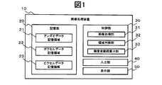
- FIG. 1 is a block diagram showing a functional configuration of an image processing apparatus according to a first embodiment of the present invention.
- Schematic of a voxel data table Schematic of a pixel data table. Schematic which showed the process which creates a projection figure using volume data.
- A Schematic diagram showing projection view of volume data from XY plane side direction (front)
- (b) Schematic diagram showing projection diagram of volume data from ZX plane side direction (lateral)
- (c) Schematic diagram showing a projection view of volume data from the XZ plane side direction (above)
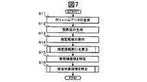
- 6 is a flowchart showing a flow of processing in the image processing apparatus according to the first embodiment.
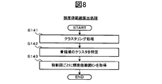
- 5 is a flowchart showing a flow of luminance value range calculation processing in the image processing apparatus according to the first embodiment.
- 6 is a flowchart showing a flow of a removal target area specifying process in the image processing apparatus according to the first embodiment.
- the block diagram which shows the functional structure of the image processing apparatus which concerns on 2nd embodiment of this invention.
- 10 is a flowchart showing a flow of processing in the image processing apparatus according to the second embodiment.
- 9 is a flowchart showing a flow of a brightness threshold calculation process in the image processing apparatus according to the second embodiment.
- the block diagram which shows the electric constitution of the image processing apparatus which concerns on 2nd embodiment of this invention.
- 60 Image processing device, 20: Storage unit, 21: Angio data storage area, 22: Voxel data storage area, 23: Pixel data storage area, 30/70: Control unit, 31/71: Image processing unit, 32 72: area determination unit, 33: luminance value range calculation unit, 73: luminance threshold value calculation unit, 40: input unit, 50: display unit, 610: volume data, 600, 620: projection view 711: voxel, 621: pixel , 700: designated area, 80: bone area, 90: blood vessel, 800: area to be removed.
- FIG. 1 is a block diagram showing a functional configuration of the image processing apparatus 10 according to the first embodiment of the present application.
- the image processing apparatus 10 includes a storage unit 20, a control unit 30, an input unit 40, and a display unit 50.
- the storage unit 20 includes an angio data storage area 21, a voxel data storage area 22, and a pixel data storage area 23.
- the angio data storage area 21 stores angio data, which is a three-dimensional image composed of a plurality of two-dimensional tomographic images, in which a specific part is imaged at a predetermined interval by a tomography apparatus (not shown).
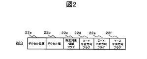
- the voxel data storage area 22 stores a voxel data table 220 for storing volume data constructed from angio data in units of voxels.
- the voxel data table 220 includes a voxel position storage field 22a, a voxel value storage field 22b, a removal target area flag storage field 22c, an XY plane side direction flag storage field 22d, and a Z- An X plane side direction flag storage field 22e and a YZ plane side direction flag storage field 22f are provided.
- the voxel position storage field 22a stores the coordinate position (X, Y, Z) of the voxel that is a component of the volume data.
- the voxel value storage field 22b stores the luminance value (voxel value V) of the voxel at the voxel position (X, Y, Z) specified by the voxel position storage field 22a.
- the removal target area flag storage field 22c stores a removal target area flag that is registered when it is determined that the voxel specified by the voxel position (X, Y, Z) is a bone area.
- the projection direction of the projection drawing including the designated region that is the basis thereof is If the direction is the XY plane side direction, it is stored in the XY plane side direction flag storage field 22d. If the direction is the ZX plane side direction, it is stored in the ZX plane side direction flag storage field 22e. If the direction is the YZ plane side direction, each direction flag is registered in the YZ plane side direction flag storage field 22f.
- a voxel is a pixel in which points are expanded in the two-dimensional direction (X, Y) and further expanded in the Z direction.
- a voxel is a cube having information in the X, Y, and Z directions constituting voxel data, and a luminance value (voxel value V) and opacity are assigned to each.
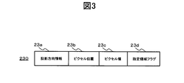
- the pixel data storage area 23 stores a pixel data table 230 for storing projections obtained by projecting volume data from an arbitrary projection direction in units of pixels.
- the pixel data table 230 includes a projection direction information storage field 23a, a pixel position storage field 23b, a pixel value storage field 23c, and a designated area flag storage field 23d.
- the projection direction information storage field 23a stores projection direction information, which is information for specifying the projection direction of the projection view.
- the projection direction information is an arbitrary direction when the volume data is projected by the control unit 30.
- the XY plane side direction (front direction), ZX plane side direction (lateral direction), XZ It may be expressed using a coordinate axis based on the development direction of the volume data, such as a plane side direction (upward direction), or an identifier such as a number (see FIGS. 5A to 5C).
- the coordinate position (X, Y) of the pixel that is a component of the projection map generated when the volume data is projected in the projection direction stored in the projection direction information storage field 23a is a component of the projection map generated when the volume data is projected in the projection direction stored in the projection direction information storage field 23a.
- Each value P) is stored.
- the designated area flag storage field 23d the pixel specified by the projection direction stored in the projection direction information storage field 23a and the pixel position (X, Y) specified by the pixel position storage field 23b are stored in the user.
- the designated area flag is registered when it is determined that it is included in the designated area designated by.
- the control unit 30 includes an image processing unit 31, an area determination unit 32, and a luminance value range calculation unit 33.
- the image processing unit 31 executes a process for generating a projection map from the volume data by the MIP method. Further, the volume data is reconstructed from the information stored in the voxel data table 220.
- the region determination unit 32 determines a specified region specified by the user on the projection view, a bone candidate region in the volume data determined based on the pixel value P of the pixel in the specified region, and a bone candidate region.
- the removal target area (bone area) in the volume data to be obtained is specified.
- the luminance value range calculation unit 33 generates a histogram indicating the distribution of each segment for the pixel value P of the pixels in the designated region, executes a process of specifying the bone region cluster, and calculates the luminance value range Cr.
- the processing executed by the control unit 30 will be specifically described with reference to FIGS. 4 and 5.
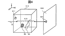
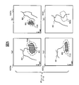
- FIG. 4 is a schematic diagram showing a process of creating a projection diagram 720 using the volume data 610
- FIG. 5A shows a projection diagram 720a of the volume data 610 from the XY plane side direction (front).
- FIG. 5B is a schematic diagram showing a projection 720b of the volume data 610 from the ZX plane side direction (lateral)
- FIG. 5C is the XZ plane direction of the volume data 610.
- FIG. 5D is a schematic diagram showing a projection diagram 700 from the XY plane side direction (front) of the volume data 610 from which the removal target area has been removed. is there.
- the image processing apparatus 10 stores a two-dimensional tomographic image (angio data) captured by a tomography apparatus (not shown) or the like in the angio data storage area 21 of the storage unit 20. Then, the image processing unit 31 reconstructs angio data at a plurality of positions corresponding to the same phase, and generates volume data 610 that is a three-dimensional image.
- the control unit 30 first performs processing using the MIP method in order to remove the bone region 80 as the removal target region 800 and display the entire image of the blood vessel 90.
- the MIP method is a method for converting the volume data 610 into a two-dimensional image.
- the image processing unit 31 For each voxel that is a structural unit of the volume data 610, the image processing unit 31 is configured from an arbitrary direction (in this embodiment, the XY plane side direction (front), the ZX plane side direction (horizontal), X ⁇ Three directions in the Z plane side direction (upward)), and the virtual ray R is irradiated. Then, the maximum voxel value Vmax is detected from the N voxel sets 615 existing on the virtual ray R. Further, the image processing unit 31 determines this detection value as the pixel value P of the pixel 621 on the projection diagram 720 existing on the virtual ray R, and generates a projection diagram 720 for each projection direction (XY plane side). The projection of the direction is represented as 620a, the projection of the ZZ plane side direction as 620b, and the projection of the XZ plane side direction as 620c).
- the area determination unit 32 displays each projection view (for example, FIG. 5A to FIG. 5C) on the display device 5 included in the display unit 50, and the projection views 720a to 620c via the input unit 40.
- a rough designation region selection operation is accepted from the user so that the bone region 80 becomes the maximum region in the designated region.
- the designated area may include pixels representing blood vessels and the like.
- the designated area is determined as the designated area 700 in pixel units, and the area determination unit 32 specifies the pixel position of the pixel included in the designated area 700.
- the region determination unit 32 detects voxels existing on the virtual ray R that projects the pixels in the designated region 700 and has a voxel value V corresponding to a luminance value range Cr described later, as a bone candidate region. Identify. Further, voxels determined to correspond to bone candidate regions in all projection directions are determined as removal target regions 800 to be removed.
- the luminance value range calculation unit 33 performs a clustering process described later on the pixels in the designated region 700, and calculates a luminance value range Cr for specifying the luminance values of the pixels and voxels that are bone region candidates.
- the angio data stored in the angio data storage area 21 may be acquired in any way, or may be directly acquired from the tomography apparatus by including an I / F unit that is directly connected to the tomography apparatus.
- the communication unit may be provided and acquired from a network such as the Internet.
- the input unit 40 is a user interface for receiving input from an operator, and includes a pointing device for operating graphics indicating a target operation on the GUI.
- the pointing device may be, for example, a mouse or a touch panel that directly contacts the screen.
- the display unit 50 includes a display device for displaying at least each generated image and the like, and the display device is selected from CRT (Cathode Ray Tube), LCD (Liquid Crystal Display), and the like.
- CRT Cathode Ray Tube
- LCD Liquid Crystal Display
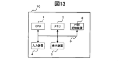
- FIG. 13 is a block diagram showing an electrical configuration of the image processing apparatus 10.
- the image processing apparatus 10 is a general computer on which a program operates, for example, a personal computer or a workstation.
- the image processing apparatus 10 includes a CPU (Central Processing Unit) 1 that is a main part of a computer and controls each apparatus centrally, and a memory 2 that stores various data in a rewritable manner. Further, the image processing apparatus 10 displays an external storage device 3 that stores various programs, data generated by the programs, an input device 4 such as a keyboard and a mouse for performing various operation instructions, and image data. Display device 5. Each of these devices is connected to the CPU 1 through a signal line 6 such as a bus. Of course, you may provide the communication apparatus for communicating with an external apparatus other than that.
- a signal line 6 such as a bus.
- the CPU 1 executes various processes by, for example, loading a program stored on the external storage device 3 onto the memory 2 and executing it.
- the program may be downloaded from the network to the external storage device 3 via a communication device, and then loaded onto the memory 2 and executed by the CPU 1.
- the external storage device 3 includes, for example, an HDD (Hard Disk Drive), but is not limited to the HDD.
- the computer software that is a distributed program and a mechanism for reading data include a CD-ROM, A drive such as a DVD-ROM may be further provided.
- the image processing unit 31 of the image processing apparatus 10 reads arbitrary angio data stored in the angio data storage area 21, stacks and reconstructs a plurality of images corresponding to the same phase on the axis, Data is generated (S11).
- the image processing unit 31 stores information about each voxel that is a component of the volume data in the voxel data table 220 stored in the voxel data storage area 22. That is, the coordinate position (X, Y, Z) of each voxel is stored in the voxel position storage field 22a, and the voxel value V of the voxel specified by the voxel position storage field 22a is stored in the voxel value storage field 22b.
- the image processing unit 31 projects the generated volume data from an arbitrary projection direction by the MIP method described above to generate a plurality of projection views (S12).
- a plurality of projection views S12
- three projection views are generated by projecting from three directions of the XY plane side direction, the ZX plane side direction, and the XZ plane side direction.
- the image processing unit 31 stores information about each pixel, which is a component of these projection views, in the pixel data table 230 stored in the pixel data storage area 23.
- the projection direction information for specifying the projection direction of the projection diagram formed by the pixels is projected to the projection direction information storage field 23a in the projection direction projected in the projection direction stored in the projection direction information storage field 23a.
- the coordinate position (X, Y) is stored in the pixel position storage field 23b, and the pixel value P of the pixel specified by the projection direction information storage field 23a and the pixel position storage field 23b is stored in the pixel value storage field 23c. .
- the region determination unit 32 displays each projection view on the display device 5 provided in the display unit 50, and a rough bone region in which the bone region becomes the maximum region from the user via the input unit 40. Is accepted as a designated area (S13). For example, when the designated area is designated by the user, the area determining unit 32 detects the projection direction of the designated projection view of the designated area on the display device 5, and stores the projection direction information storage field of the pixel data table 230. From 23a, the record in which the matching projection direction is stored is specified. Then, in the pixel position storage field 23b in the specified record, a record in which a pixel position that matches the coordinate position of the pixel in the designated area is further extracted. Subsequently, the area determination unit 32 registers the specified area flag in the specified area flag storage field 23d of the extracted record, and specifies the pixel corresponding to the specified area.
- any method may be used for designating the designated area.
- the user may be configured to determine a region by drawing a free closed curve using a mouse or the like.
- the region may be designated by changing the size or position of a preset circle or the like.
- the luminance value range calculation unit 33 calculates a luminance value range (S14). The calculation process of the luminance value range will be described using the flowchart shown in FIG.
- the luminance value range calculation unit 33 first performs a clustering process on the pixel value range (S141).
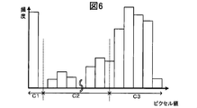
- FIG. 6 is a histogram representing the distribution of pixels, with the vertical axis representing frequency (frequency) and the horizontal axis representing pixel values P for all the pixels included in each designated region.
- the luminance value range calculation unit 33 divides the section of the pixel value P into clusters as shown in FIG. 6 according to the frequency. For example, in the histogram of FIG. 6, the range of the pixel value P is divided into three clusters C1, C2, and C3.
- a fuzzy C-Means method using a membership function, which is a known method, can be used.
- the FCM is an extension of the K-Means method with the idea of attribution.
- the K-Means method is a clustering method when the number of clusters (K) is determined in advance, and in this embodiment, the number of clusters needs at least three of a background region, a blood vessel region, and a bone region. .
- a central value is appropriately given as a representative point of the cluster, each element is assigned to the cluster of the closest central value, and the membership value of each pixel with respect to the central value (the degree of belonging to all clusters) is obtained. Pixels belong to multiple clusters at the same time. Thereafter, a new cluster center value is calculated for each cluster from the membership value to obtain a new cluster. These operations are repeated until each central value does not change, and the clustering is terminated when the specified parameter (convergence condition) or less is reached.
- the parameters required for this clustering may be predetermined values that may be set in advance, or may be arbitrarily input by the user.
- the luminance value range calculation unit 33 specifies a cluster representing a pixel corresponding to the bone region among the clusters (S142).
- the pixel representing the bone region occupies the largest range in the designated region that is roughly specified manually by the user so that the bone region becomes the maximum region. Further, it can be assumed that there are mainly pixels representing blood vessels having a pixel value P smaller than that of the bone region and background regions having a pixel value P smaller than pixels representing the blood vessel.
- the cluster C1 is estimated to be a set of pixels in the background region because the pixel value P is minimum and the pixel value P range is also small.
- the cluster C2 is estimated to be a set of pixels representing blood vessels, and the cluster C3 has both a large pixel value P and a high frequency within the designated area. It is estimated that this is a set of pixels representing a bone region occupying a large area.
- the luminance value range calculation unit 33 specifies the cluster C3 as a bone region pixel.
- the method of specifying the bone region and the clustering process are not limited to those described above, and any method may be used.
- the luminance value range calculation unit 33 performs luminance value ranges Cr1, Cr2, and Cr3 (Cr1: luminance value range of the designated area of the XY plane side direction projection drawing, Cr2: Z for each designated area of each projection drawing. -Calculates the luminance value range of the designated area of the X plane side direction projection view, Cr3: the luminance value range of the designated area of the YZ plane side direction projection view; (S143).
- the luminance value range calculation unit 33 detects the lowest pixel value Pmin and the maximum pixel value Pmax from the pixel set of the cluster C3 estimated to be a bone region, and determines the range of Pmin to Pmax as a cluster. Acquired as a luminance value range Cr of C3.
- the region determination unit 32 scans the voxels on the virtual ray R in the projection direction for each pixel in the designated region, and converts the voxel having the voxel value V included in the luminance value range Cr to the bone.
- the candidate area is specified (S15).
- the region determination unit 32 detects a bone candidate region based on the luminance value range Cr1 in the designated region of the projection view in the XY plane side direction.
- the area determination unit 32 registers the specified area flag in the specified area flag storage field 23d of the pixel data table 230, and the projection direction information specifies the XY plane side direction in the projection direction information storage field 23a. Extracts records that store information. Then, the pixel position is acquired from the pixel position storage field 23b of the extracted record.
- the area determination unit 32 detects the coordinate positions of all the voxels located on the virtual ray R from the pixel position and the projection direction information (here, the XY plane side direction). For example, if the pixel position is (A, B), the voxel whose coordinate position is (A, B, (1 to Zn)) is the object of scanning (Zn is the Z direction) Number of voxels).
- the area determination unit 32 stores the voxel position that matches the coordinate position (A, B, (1 to Zn)) of the voxel located on the virtual ray R from the voxel position storage field 22a of the voxel data table 220. Extracted records. The area determination unit 32 further extracts a record in which the voxel value V stored in the voxel value storage field 22b of the extracted record corresponds to the luminance value range Cr1.
- the area determining unit 32 registers the direction flag in the XY plane side direction flag storage field 22d of the extracted record.
- the above processing is executed for all the pixels in the designated area.
- the area determination unit 32 uses the luminance value range Cr2 for the pixels in the designated area of the projection view in the ZX plane side direction, and in the designated area of the projection view in the XZ plane side direction. Similar processing is performed on the pixel using the luminance value range Cr3.
- the region determination unit 32 specifies voxels specified as bone candidate regions in all projection directions as removal target regions (S16).
- removal target area specifying process will be described with reference to the flowchart shown in FIG.
- the image processing unit 31 stores all of the XY plane side direction flag storage field 22d, the ZX plane side direction flag storage field 22e, and the YZ plane side direction flag storage field 22f.
- the record other than the record in which the direction flag is registered is specified.
- the image processing unit 31 projects the volume data consisting only of the voxel data stored in this record from any projection direction to generate a projection view, and displays it on the display device 5 of the display unit 50 (S151, (Refer FIG.5 (d)).
- the region determination unit 32 receives a confirmation of the removal target region from the user via the input unit 40 (S152).
- the user when the bone region is removed and a desired result is obtained in the projection diagram displayed on the display device 5, the user performs an instruction operation for permitting confirmation of the removal target region via the input unit 40. can do.
- the desired result is not obtained, for example, the bone region has not been completely removed, it is possible to input a re-editing instruction operation via the input unit 40 (S154).
- step 152 if the removal target area confirmation permission is accepted (YES), the area determination unit 32 reads the XY plane side direction flag storage field 22d and the ZX plane side direction flag storage field 22e from the voxel data table 220. And the YZ plane side direction flag storage field 22f, the records in which the direction flag is registered in all are extracted from the voxel data table 220, and the removal target area flag storage field 22c of these records is included in the removal target. The region flag is registered, the voxel corresponding to the removal target region is specified, and the process ends (S153).
- step 154 when a re-editing instruction operation is accepted (YES), the area determination unit 32 jumps to the step of the re-editing point.
- the re-editing point is provided with a plurality of points such as designation of a designated region (S13) and cluster specification of a bone region (S143), and the user can select a predetermined re-editing point.
- the image processing unit 31 reconstructs the volume data by removing the voxels specified as the removal target area from the volume data for which the removal target area is specified in this way.
- the process of removing the removal target area is, for example, by calculating an average value of the pixel values of the cluster (see C1 in FIG. 6) that is estimated to be the background area during the clustering process. This can be realized by overwriting the average value on the voxel value V of the registered voxel.
- the present invention is not limited to this method, and a process of subtracting and synthesizing the voxel value V of the voxel in which the removal target region flag is registered may be executed.
- a specified value may be used for the pixel section that is a unit of the frequency distribution, or a configuration that can be set by the user may be used.
- the image processing unit 31 can use a predetermined value for the voxel value V of the voxel in the area to be removed when displaying the projection view from which the bone area has been removed (see FIG. 5D). It is. With such a configuration, the color or the like of the area to be removed changes, so that the user can more intuitively confirm whether or not the removal process has been executed.
- the removal target region is not limited to the bone region.
- a voxel having a large luminance value such as noise may be determined as a removal target.
- the image processing apparatus 10 identifies a bone region to be removed by clustering processing from a plurality of roughly specified regions so that the bone region becomes the maximum region.
- the user can remove a spatially desired region by a simple operation.
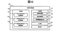
- the image processing device 60 includes a storage unit 20, a control unit 70, an input unit 40, and a display unit 50.
- the image processing device 60 according to the second embodiment differs from the image processing device 10 according to the first embodiment in the processing executed by the control unit 70, hereinafter, matters related thereto are described. explain.
- the control unit 70 includes an image processing unit 71, a region determination unit 72, and a luminance threshold value calculation unit 73. These processes will be specifically described with reference to FIGS. 4 and 5.
- the image processing unit 71 executes a process for generating a projection map from the volume data by the MIP method. Further, the volume data is reconstructed from the information stored in the voxel data table 220.
- the area determination unit 72 receives, from the user, an operation for specifying a rough bone area 80 such that the bone area becomes the maximum area on the projection diagram 720 via the input unit 40, and the designation region 700 for each projection diagram. And the pixel position included in the designated area 700 is specified. Furthermore, the region determination unit 72 determines a voxel having a voxel value V equal to or higher than a later-described luminance threshold ThP and equal to or higher than ThV on the virtual ray R that projects each pixel in the designated region as a bone candidate region. . Furthermore, the voxel determined to correspond to the bone candidate region for all projection directions is specified as the removal target region 800 to be removed.
- the luminance threshold value calculation unit 73 detects the maximum pixel value Pmax among the pixel values P of the pixels included in each designated area 700. Subsequently, the luminance threshold value calculation unit 73 scans the voxels on the virtual ray R that projects the pixels included in the designated region 700, and detects the maximum voxel value Vmax. The luminance threshold value calculation unit 73 multiplies the pixel value Pmax by the parameter A and the voxel value Vmax by the parameter B, thereby calculating the luminance threshold value ThP and ThV.
- the luminance threshold ThP and ThV are values provided for specifying the range of the voxel value V estimated as the bone region. In the present embodiment, the conditions of ThP ⁇ V and ThV ⁇ V are satisfied. A voxel having the voxel value V is determined as a bone candidate region.
- a parameter A and a parameter B are provided. Therefore, the parameter A and the parameter B are values of 1 or less, and in the present embodiment, for example, the values are preferably about 0.8.
- the parameter A and the parameter B can be freely set by the user in consideration of the luminance value of the angio data.
- steps 21 to 23 in FIG. 11 are the same as the processes in steps 11 to 13 executed in the image processing apparatus 10 according to the first embodiment, and thus detailed description thereof is omitted here. .
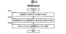
- FIG. 12 is a flowchart illustrating a brightness threshold value calculation process executed by the image processing apparatus 60 according to the second embodiment.
- the luminance threshold value calculation unit 73 calculates the maximum pixel values Pmax1, Pmax2, and Pmax3 (Pmax1: the maximum pixel in the designated area of the XY plane side projection view from the pixel value P of the pixel included in the designated area in each projection view.
- Pmax3 Maximum pixel value P in the designated area of the YZ plane direction projection view; (Denoted as Pmax) is detected (S241).
- Pmax1 the maximum pixel in the designated area of the XY plane side projection view from the pixel value P of the pixel included in the designated area in each projection view.
- Value Pmax2 Maximum pixel value PZ3 in the designated area of the ZX plane side direction projection view
- Pmax3 Maximum pixel value P in the designated area of the YZ plane direction projection view
- the specified area flag is registered in the specified area flag storage field 23d of the pixel data table 230, and information for specifying the XY plane side direction is stored in the projection direction information storage field 23a. Extract records. Next, the maximum pixel value Pmax1 is detected from the pixel value storage field 23c of the extracted record.
- the luminance threshold value calculation unit 73 further scans the voxels on the virtual ray R in the projection direction for all the pixels included in the designated region in each projection view, and obtains the maximum voxel value Vmax (X, Y, Z). It is detected (S242). For example, the luminance threshold value calculation unit 73 stores the specified area flag in the specified area flag storage field 23d of the pixel data table 230, and stores information for specifying the XY plane side direction in the projection direction information storage field 23a. Extracted records. Then, the pixel position is acquired from the pixel position storage field 23b of the extracted record.
- the luminance threshold value calculation unit 73 detects the coordinate positions of all the voxels located on the virtual ray R from the pixel position and the projection direction information (here, the direction on the XY plane). For example, if the pixel position is (A, B) and the projection direction information specifies the XY plane side direction, the coordinate position of the voxel is (A, B, (1 to Zn)). Voxels that are to be scanned (Zn is the number of voxels in the Z direction).
- the luminance threshold value calculation unit 73 has a voxel position matching the coordinate position (A, B, (1 to Zn)) of the voxel located on the virtual ray R from the voxel position storage field 22a of the voxel data table 220. Extract stored records. The luminance threshold value calculation unit 73 detects the maximum voxel value Vmax from the voxel value storage field 22b of the extracted record.
- the luminance threshold value calculation unit 73 calculates a luminance threshold value ThP1 based on the pixel value Pmax1 and a luminance threshold value ThV based on the voxel value Vmax. (S243). For example, the luminance threshold value calculation unit 73 multiplies the pixel value Pmax1 by the parameter A, and multiplies the voxel value Vmax detected for each virtual ray R that projects each pixel in the designated region by the parameter B to obtain the luminance threshold value ThP1. , ThV for each pixel is calculated. These processes are executed for each designated area, and the luminance threshold value in the ZX plane side direction and the luminance threshold value in the YZ plane side direction are also calculated.
- the region determination unit 72 scans the voxels on the virtual ray R that projects each pixel of the designated region of each projection view, and the luminance threshold ThP or more and from above the virtual ray R of the pixel.
- a voxel having a voxel value V equal to or greater than ThV calculated from the detected Vmax is specified as a bone candidate region (S26).
- S26 a bone candidate region
- the area determination unit 72 registers the specified area flag in the specified area flag storage field 23d of the pixel data table 230, and the projection direction information specifies the XY plane side direction in the projection direction information storage field 23a. Extracts records that store information. Then, the pixel position is acquired from the pixel position storage field 23b of the extracted record.
- the area determination unit 72 detects the coordinate positions of all the voxels located on the virtual ray R from the pixel position and the projection direction information (here, the XY plane side direction). Subsequently, the region determination unit 72 extracts a record storing a voxel position that matches the coordinate position of the voxel located on the virtual ray R from the voxel position storage field 22a of the voxel data table 220. The area determination unit 72 stores a voxel value V equal to or greater than the luminance threshold ThP1 and greater than ThV calculated from Vmax detected from the virtual ray R of the pixel from the voxel value storage field 22b of the extracted record.
- the direction flag is registered in the XY plane direction flag storage field 22d of the extracted record.
- the area determination unit 72 for pixels in the designated area of the projected view in the ZX plane side direction, has a luminance threshold ThP2 or more and voxels of ThV or more detected from the virtual ray R of the pixel.
- the value V is equal to or greater than the luminance threshold ThP3 and equal to or greater than ThV calculated from Vmax detected from the virtual ray R of the pixel.
- the voxels having the voxel value V are scanned, and the direction flag is registered for each of them.
- step 26 Since the process of step 26 is the same process as step 16 executed by the image processing apparatus 10 according to the first embodiment, detailed description thereof is omitted.
- the image processing unit 71 reconstructs the volume data by removing the voxels specified as the removal target area from the volume data for which the removal target area is specified.
- re-editing points used in the processing of step 26 can be provided with points such as designation of a designated area (S23) and change of parameters A and B in step 243, for example.
- the image processing apparatus 60 spatially removes bones to be removed from the rough designated areas in the plurality of projection views using the luminance values and parameters of the bone areas.
- the area can be specified, and the user can remove the desired area by a simple operation.
Landscapes
- Engineering & Computer Science (AREA)
- Health & Medical Sciences (AREA)
- Life Sciences & Earth Sciences (AREA)
- Medical Informatics (AREA)
- Physics & Mathematics (AREA)
- Biomedical Technology (AREA)
- Animal Behavior & Ethology (AREA)
- Biophysics (AREA)
- High Energy & Nuclear Physics (AREA)
- Veterinary Medicine (AREA)
- Nuclear Medicine, Radiotherapy & Molecular Imaging (AREA)
- Optics & Photonics (AREA)
- Pathology (AREA)
- Radiology & Medical Imaging (AREA)
- Public Health (AREA)
- Heart & Thoracic Surgery (AREA)
- Molecular Biology (AREA)
- Surgery (AREA)
- General Health & Medical Sciences (AREA)
- Computer Vision & Pattern Recognition (AREA)
- General Physics & Mathematics (AREA)
- Theoretical Computer Science (AREA)
- Human Computer Interaction (AREA)
- Oral & Maxillofacial Surgery (AREA)
- Vascular Medicine (AREA)
- Dentistry (AREA)
- Computer Graphics (AREA)
- Apparatus For Radiation Diagnosis (AREA)
- Image Processing (AREA)
- Image Generation (AREA)
- Image Analysis (AREA)
Priority Applications (1)
| Application Number | Priority Date | Filing Date | Title |
|---|---|---|---|
| US12/810,918 US8452066B2 (en) | 2008-02-13 | 2008-12-25 | Image processing apparatus, image processing method, and program |
Applications Claiming Priority (2)
| Application Number | Priority Date | Filing Date | Title |
|---|---|---|---|
| JP2008031992A JP5334423B2 (ja) | 2008-02-13 | 2008-02-13 | 画像処理装置、画像処理方法、およびプログラム |
| JP2008-031992 | 2008-02-13 |
Publications (1)
| Publication Number | Publication Date |
|---|---|
| WO2009101754A1 true WO2009101754A1 (ja) | 2009-08-20 |
Family
ID=40956790
Family Applications (1)
| Application Number | Title | Priority Date | Filing Date |
|---|---|---|---|
| PCT/JP2008/073519 Ceased WO2009101754A1 (ja) | 2008-02-13 | 2008-12-25 | 画像処理装置、画像処理方法、およびプログラム |
Country Status (3)
| Country | Link |
|---|---|
| US (1) | US8452066B2 (enExample) |
| JP (1) | JP5334423B2 (enExample) |
| WO (1) | WO2009101754A1 (enExample) |
Families Citing this family (8)
| Publication number | Priority date | Publication date | Assignee | Title |
|---|---|---|---|---|
| US8634626B2 (en) * | 2010-06-29 | 2014-01-21 | The Chinese University Of Hong Kong | Registration of 3D tomography images |
| US8867806B2 (en) * | 2011-08-01 | 2014-10-21 | Impac Medical Systems, Inc. | Method and apparatus for correction of errors in surfaces |
| US9153045B2 (en) | 2012-03-22 | 2015-10-06 | The Cleveland Clinic Foundation | Augmented reconstruction for computed tomography |
| JP6546385B2 (ja) * | 2014-10-02 | 2019-07-17 | キヤノン株式会社 | 画像処理装置及びその制御方法、プログラム |
| DE102015224356B4 (de) | 2015-12-04 | 2017-09-14 | Siemens Healthcare Gmbh | Verfahren zur Bildunterstützung eines Behandlers, Röntgeneinrichtung und Computerprogramm |
| CN109643441B (zh) | 2016-08-30 | 2023-07-18 | 佳能株式会社 | 图像处理装置、图像处理方法、计算机可读取的存储介质、图像处理系统 |
| US10089758B1 (en) * | 2017-03-29 | 2018-10-02 | Carestream Health, Inc. | Volume image reconstruction using projection decomposition |
| WO2019065466A1 (ja) * | 2017-09-29 | 2019-04-04 | キヤノン株式会社 | 画像処理装置、画像処理方法、およびプログラム |
Citations (1)
| Publication number | Priority date | Publication date | Assignee | Title |
|---|---|---|---|---|
| JP2006323653A (ja) * | 2005-05-19 | 2006-11-30 | Ziosoft Inc | 画像処理方法および画像処理プログラム |
Family Cites Families (2)
| Publication number | Priority date | Publication date | Assignee | Title |
|---|---|---|---|---|
| JP3929217B2 (ja) * | 2000-01-12 | 2007-06-13 | 学校法人日本大学 | X線ct撮影方法及びその装置 |
| JP4761741B2 (ja) * | 2004-09-06 | 2011-08-31 | 株式会社東芝 | X線ct装置、画像データ領域抽出システムおよび画像データ領域抽出プログラム |
-
2008
- 2008-02-13 JP JP2008031992A patent/JP5334423B2/ja not_active Expired - Fee Related
- 2008-12-25 US US12/810,918 patent/US8452066B2/en active Active
- 2008-12-25 WO PCT/JP2008/073519 patent/WO2009101754A1/ja not_active Ceased
Patent Citations (1)
| Publication number | Priority date | Publication date | Assignee | Title |
|---|---|---|---|---|
| JP2006323653A (ja) * | 2005-05-19 | 2006-11-30 | Ziosoft Inc | 画像処理方法および画像処理プログラム |
Also Published As
| Publication number | Publication date |
|---|---|
| US8452066B2 (en) | 2013-05-28 |
| JP5334423B2 (ja) | 2013-11-06 |
| US20110019890A1 (en) | 2011-01-27 |
| JP2009189489A (ja) | 2009-08-27 |
Similar Documents
| Publication | Publication Date | Title |
|---|---|---|
| JP5334423B2 (ja) | 画像処理装置、画像処理方法、およびプログラム | |
| JP5197029B2 (ja) | 医用画像処理装置 | |
| US9478022B2 (en) | Method and system for integrated radiological and pathological information for diagnosis, therapy selection, and monitoring | |
| JP5224451B2 (ja) | 投影画像作成装置、方法およびプログラム | |
| CN104508710B (zh) | 对图像数据中的选择性组织的视觉抑制 | |
| US9053565B2 (en) | Interactive selection of a region of interest in an image | |
| JP5161217B2 (ja) | 画像中のボクセルのクラスター・マップを再構成する方法 | |
| JP5643304B2 (ja) | 胸部トモシンセシスイメージングにおけるコンピュータ支援肺結節検出システムおよび方法並びに肺画像セグメント化システムおよび方法 | |
| JP2015515296A (ja) | 対象物の画像情報の提供 | |
| JP2002109510A (ja) | 異常陰影候補検出処理システム | |
| JP5049654B2 (ja) | 医用画像処理装置、及び医用画像処理方法 | |
| JP2010528750A (ja) | 管状構造の検査 | |
| JP5492024B2 (ja) | 領域分割結果修正装置、方法、及びプログラム | |
| US20100034439A1 (en) | Medical image processing apparatus and medical image processing method | |
| EP3729368B1 (en) | System and method for assessing a pulmonary image | |
| JP5194138B2 (ja) | 画像診断支援装置およびその動作方法、並びに画像診断支援プログラム | |
| US10297089B2 (en) | Visualizing volumetric image of anatomical structure | |
| JP2012085833A (ja) | 3次元医用画像データの画像処理システム、その画像処理方法及びプログラム | |
| JP2007151645A (ja) | 医用画像診断支援システム | |
| JP5122650B2 (ja) | 経路近傍レンダリング | |
| JP2010167067A (ja) | 医用画像処理装置及びプログラム | |
| US10984294B2 (en) | Apparatus for identifying objects from an object class | |
| JPWO2011062108A1 (ja) | 画像処理装置及び画像処理方法 | |
| WO2017018230A1 (ja) | 画像処理装置、方法、及びプログラム |
Legal Events
| Date | Code | Title | Description |
|---|---|---|---|
| 121 | Ep: the epo has been informed by wipo that ep was designated in this application |
Ref document number: 08872363 Country of ref document: EP Kind code of ref document: A1 |
|
| WWE | Wipo information: entry into national phase |
Ref document number: 12810918 Country of ref document: US |
|
| NENP | Non-entry into the national phase |
Ref country code: DE |
|
| 122 | Ep: pct application non-entry in european phase |
Ref document number: 08872363 Country of ref document: EP Kind code of ref document: A1 |