WO2009098973A1 - Dispositif de diagnostic à ultrasons - Google Patents
Dispositif de diagnostic à ultrasons Download PDFInfo
- Publication number
- WO2009098973A1 WO2009098973A1 PCT/JP2009/051300 JP2009051300W WO2009098973A1 WO 2009098973 A1 WO2009098973 A1 WO 2009098973A1 JP 2009051300 W JP2009051300 W JP 2009051300W WO 2009098973 A1 WO2009098973 A1 WO 2009098973A1
- Authority
- WO
- WIPO (PCT)
- Prior art keywords
- image
- tissue
- tomographic
- displacement
- elastic
- Prior art date
Links
Images


Classifications
-
- A—HUMAN NECESSITIES
- A61—MEDICAL OR VETERINARY SCIENCE; HYGIENE
- A61B—DIAGNOSIS; SURGERY; IDENTIFICATION
- A61B8/00—Diagnosis using ultrasonic, sonic or infrasonic waves
- A61B8/08—Detecting organic movements or changes, e.g. tumours, cysts, swellings
- A61B8/0825—Detecting organic movements or changes, e.g. tumours, cysts, swellings for diagnosis of the breast, e.g. mammography
-
- A—HUMAN NECESSITIES
- A61—MEDICAL OR VETERINARY SCIENCE; HYGIENE
- A61B—DIAGNOSIS; SURGERY; IDENTIFICATION
- A61B8/00—Diagnosis using ultrasonic, sonic or infrasonic waves
- A61B8/42—Details of probe positioning or probe attachment to the patient
- A61B8/4245—Details of probe positioning or probe attachment to the patient involving determining the position of the probe, e.g. with respect to an external reference frame or to the patient
- A61B8/4254—Details of probe positioning or probe attachment to the patient involving determining the position of the probe, e.g. with respect to an external reference frame or to the patient using sensors mounted on the probe
-
- A—HUMAN NECESSITIES
- A61—MEDICAL OR VETERINARY SCIENCE; HYGIENE
- A61B—DIAGNOSIS; SURGERY; IDENTIFICATION
- A61B8/00—Diagnosis using ultrasonic, sonic or infrasonic waves
- A61B8/46—Ultrasonic, sonic or infrasonic diagnostic devices with special arrangements for interfacing with the operator or the patient
- A61B8/461—Displaying means of special interest
- A61B8/463—Displaying means of special interest characterised by displaying multiple images or images and diagnostic data on one display
-
- A—HUMAN NECESSITIES
- A61—MEDICAL OR VETERINARY SCIENCE; HYGIENE
- A61B—DIAGNOSIS; SURGERY; IDENTIFICATION
- A61B8/00—Diagnosis using ultrasonic, sonic or infrasonic waves
- A61B8/48—Diagnostic techniques
- A61B8/485—Diagnostic techniques involving measuring strain or elastic properties
-
- G—PHYSICS
- G01—MEASURING; TESTING
- G01S—RADIO DIRECTION-FINDING; RADIO NAVIGATION; DETERMINING DISTANCE OR VELOCITY BY USE OF RADIO WAVES; LOCATING OR PRESENCE-DETECTING BY USE OF THE REFLECTION OR RERADIATION OF RADIO WAVES; ANALOGOUS ARRANGEMENTS USING OTHER WAVES
- G01S7/00—Details of systems according to groups G01S13/00, G01S15/00, G01S17/00
- G01S7/52—Details of systems according to groups G01S13/00, G01S15/00, G01S17/00 of systems according to group G01S15/00
- G01S7/52017—Details of systems according to groups G01S13/00, G01S15/00, G01S17/00 of systems according to group G01S15/00 particularly adapted to short-range imaging
- G01S7/52023—Details of receivers
- G01S7/52036—Details of receivers using analysis of echo signal for target characterisation
- G01S7/52042—Details of receivers using analysis of echo signal for target characterisation determining elastic properties of the propagation medium or of the reflective target
-
- G—PHYSICS
- G01—MEASURING; TESTING
- G01S—RADIO DIRECTION-FINDING; RADIO NAVIGATION; DETERMINING DISTANCE OR VELOCITY BY USE OF RADIO WAVES; LOCATING OR PRESENCE-DETECTING BY USE OF THE REFLECTION OR RERADIATION OF RADIO WAVES; ANALOGOUS ARRANGEMENTS USING OTHER WAVES
- G01S7/00—Details of systems according to groups G01S13/00, G01S15/00, G01S17/00
- G01S7/52—Details of systems according to groups G01S13/00, G01S15/00, G01S17/00 of systems according to group G01S15/00
- G01S7/52017—Details of systems according to groups G01S13/00, G01S15/00, G01S17/00 of systems according to group G01S15/00 particularly adapted to short-range imaging
- G01S7/52053—Display arrangements
- G01S7/52057—Cathode ray tube displays
- G01S7/52068—Stereoscopic displays; Three-dimensional displays; Pseudo 3D displays
- G01S7/52069—Grey-scale displays
Definitions
- the present invention relates to an ultrasonic diagnostic apparatus, and specifically, a tomographic image in which an elastic image representing the hardness or softness of a tissue of a subject is obtained on a living body simulation image such as an illustration or a photograph simulating the subject.
- the present invention relates to an ultrasonic diagnostic apparatus that displays or records a mark indicating a position in a superimposed manner.
- the ultrasonic diagnostic apparatus transmits ultrasonic waves to the inside of the subject via the ultrasonic probe and receives an ultrasonic echo signal corresponding to the structure of the living tissue from the inside of the subject.
- An image such as an image is generated and used for diagnosis.
- RF signal frame data is acquired while applying pressure to an object with an ultrasonic probe by a manual or mechanical method, and a pair with different acquisition times is acquired. Based on the RF signal frame data, a displacement of each part of the living body caused by the compression is obtained, and an elastic image representing the hardness or softness of the living tissue is generated based on the displacement data.
- Patent Document 2 a tomographic image of a subject is displayed, and a probe mark indicating a scanning position of a probe is provided at a position where a tomographic image on an illustration (body mark) image simulating a living body is acquired. It is described that it is displayed in a superimposed manner. If the tomographic image and the living body simulation image on which the probe mark is superimposed are recorded in association with each other, it is considered that the tomographic image can be easily associated with the examination site where the image is acquired after the ultrasonic examination.
- Patent Document 2 displays information such as an examination site by marking the living body simulated image with respect to the elastic image, or records the living body simulated image marked with the testing site in association with the elasticity image. Is not considered.
- the technique described in Patent Document 2 detects a living body simulated image by detecting the coordinates of the probe with a sensor such as a magnetic sensor attached to the ultrasonic probe and aligning it with the coordinates of the living body simulated image.
- the inspection site of the tomographic image is marked on the top.
- the elastic image is displaced in the tissue of the tomographic site by repeatedly applying pressure to the subject using, for example, an ultrasonic probe, or using pressure changes such as the pulsation of the subject. It is generated based on a pair of RF signal frame data obtained in the generated state. Therefore, it is difficult to detect that the elastic image has been properly acquired with the technique described in Patent Document 2, and it is difficult to grasp the acquisition position of the elastic image.
- an object of the present invention is to realize an ultrasonic diagnostic apparatus capable of detecting a tomographic region of a subject from which an elasticity image has been acquired and displaying or recording an image obtained by superimposing the tomographic region on a living body simulated image.
- an ultrasonic diagnostic apparatus includes an ultrasonic probe that transmits and receives ultrasonic waves to and from a subject, and a reflected echo signal that is measured by the ultrasonic probe.
- Elastic image that generates the elasticity image representing the hardness or softness of the tissue of the tomographic region based on the phasing and adding means for generating the RF signal frame data of the tomographic region of the specimen and a pair of RF signal frame data having different acquisition times
- biological simulation image generation means for generating a biological simulation image that simulates a subject, a position sensor that is attached to an ultrasonic probe and detects the three-dimensional coordinate position and orientation of the probe, and a position sensor
- a tomographic part detecting means for detecting position information of a tomographic part of the subject based on an output from the tissue, a tissue displacement detecting means for detecting that the tissue of the tomographic part of the subject is displaced, and a displacement of the tissue is detected
- the tissue displacement detection means by providing the tissue displacement detection means, it is possible to detect that the tissue of the tomographic site of the subject is displaced, so that it is detected that the elasticity image has been appropriately acquired. can do. Therefore, a mark can be superimposed on the position where the elastic image on the living body simulated image is acquired based on the position information of the tomographic part of the subject when this is detected.
- the examination efficiency can be improved, and by recording in the memory in association with the elastic image generated when the tissue displacement is detected , Can be linked efficiently to post-test diagnosis and treatment policy decisions.
- the tissue displacement detection means can be configured in the following manner. First, among the three-dimensional coordinates of the ultrasonic probe detected by the position sensor attached to the ultrasonic probe, the tomography is caused by a periodic change in coordinates on at least one of the coordinate axes corresponding to the displacement direction of the tissue. The displacement of the tissue at the site can be detected. This can be applied to the case where an elastic image is acquired while the probe is repeatedly pressed / released with respect to the subject to cause displacement in the tissue at the tomographic site. In this case, since the probe position is periodically displaced due to the compression / release operation, the three-dimensional coordinates of the probe position sensor are monitored, and at least on any coordinate axis corresponding to the tissue displacement direction. By detecting a periodic change in coordinates, the tissue displacement of the tomographic site can be detected.
- the image processing apparatus includes a tomographic image forming unit that generates a tomographic image of a tomographic region of the subject based on the RF signal frame data, a unit that sets a tracking point in the tomographic image, and a unit that detects the position of the tracking point.
- the tissue displacement detection means can detect the displacement of the tissue at the tomographic site based on a periodic change in the direction corresponding to the displacement direction of the tissue at the position of the tracking point.
- the tissue displacement detection means measures the displacement of the distance in the direction corresponding to the tissue displacement direction between the plurality of tracking points, and periodically changes the measured value of the displacement.
- the displacement of the tissue at the tomographic site can be detected.
- the tissue displacement detection means when the correlation coefficient obtained by the correlation calculation means becomes larger than a preset threshold value, The displacement of the tissue at the tomographic site can be detected.
- the correlation value by the cross-correlation calculation of the pair of RF signal frame data is relatively low, whereas the probe causes the subject to be inspected.
- the correlation value becomes relatively high, and by detecting this, the displacement of the tissue at the tomographic site can be detected.
- the probe position is fixed and there is no displacement in the tissue of the tomographic site, the pair of RF signal frame data almost match and the correlation value indicates the upper limit. Can be excluded.
- the tissue displacement detecting means can detect the displacement of the tissue at the tomographic site by a periodic change in the measurement value of the pressure sensor. It can. This can be applied to both the case where the compression / release operation is performed by the probe and the case where the change in the internal pressure of the subject is used. In either case, since the detection value of the pressure sensor changes periodically, the displacement of the tissue at the tomographic site can be detected by detecting this.
- an ultrasonic diagnostic apparatus capable of detecting a tomographic region of a subject from which an elastic image has been acquired and displaying or recording an image obtained by superimposing the tomographic region on a living body simulated image.
- FIG. 1 is a block diagram showing the overall configuration of an ultrasonic diagnostic apparatus according to an embodiment.
- 1 ultrasonic diagnostic device 10 subject, 12 ultrasonic probe, 18 phasing addition unit, 20 tomographic image configuration unit, 28 RF frame data selection unit, 30 displacement measurement unit, 32 elastic information calculation unit, 34 elastic image Composition part, 42 interface part, 48 position information sensor, 50 coordinate calculation part, 51 tissue displacement detection part, 52 mark creation part, 54 biological simulated image composition part, 56 memory, 65, 66 tracking points, 67 displacement measurement value, 70, 71 RF signal frame data, 73 pressure measurement value, 74 tissue displacement detection switch, 85 living body simulated image, 86 elastic image acquisition mark, 87 pressure state display, 101 elastic mark, 102 elastic scale bar, 150 compression mark, 160 Blood flow mark, 161 blood flow scale bar
- FIG. 1 is a block diagram showing the overall configuration of the ultrasonic diagnostic apparatus of the present embodiment.
- the ultrasound diagnostic apparatus 1 includes an ultrasound probe 12 that is used in contact with the subject 10 and a time interval between the subject 10 via the ultrasound probe 12.
- a transmitter 14 that repeatedly transmits ultrasonic waves
- a receiver 16 that receives time-series reflected echo signals generated from the subject 10
- a transmission / reception controller 17 that controls the transmitter 14 and the receiver 16
- a receiver 16 Is provided with a phasing addition unit 18 that performs phasing addition of the reflected echo received in (1).
- a tomographic image forming unit 20 that forms a tomographic image such as a black and white tomographic image of the subject, and an output signal of the tomographic image forming unit 20 are displayed on an image display
- a black-and-white scan converter 22 is provided for conversion to suit the 26 display.
- the RF signal frame data output from the phasing addition unit 18 is stored, the RF frame data selection unit 28 that selects at least two pieces of frame data, and the displacement measurement unit that measures the displacement of the biological tissue of the subject 10 30, an elastic information calculation unit 32 that obtains strain or elastic modulus from the displacement information measured by the displacement measurement unit 30, and an elastic image configuration unit that forms a color elastic image from the strain or elastic modulus calculated by the elastic information calculation unit 32 34, and a color scan converter 36 for converting the output signal of the elastic image construction unit 34 so as to match the display of the image display 26.
- an image control unit 44 that outputs various control signals to each unit constituting the ultrasonic diagnostic apparatus, and an interface unit 42 that inputs an instruction from the examiner and outputs the instruction to the image control unit 44 are provided. .
- the ultrasonic probe 12 is formed by arranging a plurality of transducers, and has a function of transmitting and receiving ultrasonic waves to and from the subject 10 via the transducers.
- the transmission unit 14 generates a transmission pulse for generating an ultrasonic wave by driving the ultrasonic probe 12, and has a function of setting a convergence point of the transmitted ultrasonic wave to a certain depth. Yes.
- the receiving unit 16 amplifies the reflected echo signal received by the ultrasonic probe 12 with a predetermined gain to generate an RF signal, that is, a received signal.
- the phasing / adding unit 18 receives the RF signal amplified by the receiving unit 16 and performs phase control, and forms an ultrasonic beam at one or a plurality of convergence points to generate RF signal frame data.
- the tomographic image construction unit 20 receives the RF signal frame data from the phasing addition unit 18 and performs signal processing such as gain correction, log compression, detection, contour enhancement, and filter processing to obtain tomographic image data.
- the monochrome scan converter 22 includes an A / D converter that converts tomographic image data from the tomographic image construction unit 20 into a digital signal, a frame memory that stores a plurality of converted tomographic image data in time series, and a control It is configured to include a controller.
- the black and white scan converter 22 acquires tomographic frame data in the subject stored in the frame memory as one image, and reads out the acquired tomographic frame data in synchronization with the television.
- the RF frame data selection unit 28 stores a plurality of RF signal frame data from the phasing addition unit 18, and selects one set, that is, two RF signal frame data from the stored RF signal frame data group. For example, the RF signal frame data generated from the phasing adder 18 based on the time series, that is, the frame rate of the image, is sequentially stored in the RF frame data selector 28, and the stored RF signal frame data (N) is first stored. At the same time, select one RF signal frame data (X) from the RF signal frame data group (N-1, N-2, N-3 ... NM) stored in the past in time. select.
- N, M, and X are index numbers assigned to the RF signal frame data, and are natural numbers.
- the displacement measuring unit 30 performs one-dimensional or two-dimensional correlation processing from the selected set of data, that is, the RF signal frame data (N) and the RF signal frame data (X), and corresponds to each point of the tomographic image.
- a one-dimensional or two-dimensional displacement distribution related to the displacement or movement vector in the living tissue, that is, the direction and magnitude of the displacement is obtained.
- a block matching method is used to detect the movement vector.
- the block matching method divides an image into blocks consisting of N ⁇ N pixels, for example, focuses on the block in the region of interest, searches the previous frame for the block that most closely matches the block of interest, and refers to this Then, predictive encoding, that is, processing for determining the sample value by the difference is performed.
- the elasticity information calculation unit 32 calculates the strain value or elasticity of the living tissue corresponding to each point on the tomographic image from the measurement value output from the displacement measurement unit 30, for example, the movement vector and the pressure value output from the pressure measurement unit 46.
- the modulus is calculated, and an elastic image signal, that is, elastic frame data is generated based on the strain and elastic modulus.
- the strain data is calculated by spatially differentiating the movement amount of the living tissue, for example, the displacement.
- the Young's modulus Ym determines the elastic modulus of the living tissue corresponding to each point of the tomographic image, two-dimensional elastic image data can be obtained continuously.
- the nugget ratio is a ratio of a simple tensile stress applied to an object and a strain generated in parallel to the tension.
- the elastic image construction unit 34 is configured to include a frame memory and an image processing unit, and secures elastic frame data output in time series from the elastic information calculation unit 32 in the frame memory. In contrast, image processing is performed.
- the color scan converter 36 has a function of adding hue information to the elastic frame data from the elastic image construction unit 34. That is, the light is converted into the three primary colors of light, that is, red (R), green (G), and blue (B) based on the elastic frame data. For example, elastic data having a large strain is converted into a red code, and simultaneously elastic data having a small strain is converted into a blue code.
- the switching addition unit 24 includes a frame memory, an image processing unit, and an image selection unit.
- the frame memory stores tomographic image data from the black and white scan converter 22, elastic image data from the color scan converter 36, and image data output from the biological simulated image control unit 44 described later.
- the image processing unit has a function of combining the tomographic image data and the elasticity image data secured in the frame memory by changing the combining ratio.
- the luminance information and hue information of each pixel of the composite image is obtained by adding the information of the black and white tomographic image and the color elastic image at the composite ratio.
- the image selection unit selects an image to be displayed on the image display 26 from the tomographic image data, the elasticity image data in the frame memory, the composite image data of the image processing unit, and the biological simulation image data.
- the probe 12 is provided with a position information sensor 48 such as a magnetic sensor, an angular velocity sensor, or an infrared sensor. Further, a coordinate calculation unit 50 that calculates the three-dimensional coordinate position of the probe based on the output of the position information sensor 48, and a tissue displacement detection unit 51 that detects that the tissue of the tomographic part of the subject is displaced, A mark creation unit 52 is provided that generates an elastic image acquisition mark, an elastic mark, or the like based on the output of the coordinate calculation unit 50 and the output of the tissue displacement detection unit 51.
- a position information sensor 48 such as a magnetic sensor, an angular velocity sensor, or an infrared sensor.
- a coordinate calculation unit 50 that calculates the three-dimensional coordinate position of the probe based on the output of the position information sensor 48
- a tissue displacement detection unit 51 that detects that the tissue of the tomographic part of the subject is displaced
- a mark creation unit 52 is provided that generates an elastic image acquisition mark, an elastic mark, or the like based on
- a living body simulation image such as an illustration or a photograph simulating the subject is generated, and an elastic image acquisition mark generated by the mark creating unit 52 or an elastic image of the elasticity image is obtained at the position where the elasticity image on the living body simulation image is acquired.
- a living body simulated image constructing unit 54 that superimposes a simulated mark such as an elastic mark graded according to the hardness or softness of the tissue in the setting region, and positional information of the tomographic site of the subject from which the elastic image was acquired,
- a memory 56 for storing information such as elasticity information is provided.
- tissue displacement detection unit 51 that detects that the tissue of the tomographic site of the subject is displaced will be described.
- the present embodiment is an example applied when an elastic image is generated by performing a compression / release operation on a subject using a probe. For example, if an elastic image is generated while repeatedly pressing / releasing to produce a slight strain change from a state in which the probe is applied to the subject and a certain amount of stress is applied, the probe is attached to the probe.
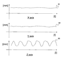
- a signal detected by the position information sensor 48 is input to the coordinate calculation unit 50, and the coordinate calculation unit 50 performs division processing on the three-dimensional coordinate axes of the X axis, the Y axis, and the Z axis as shown in FIG.
- FIG. 2 is a diagram illustrating an example of changes in the coordinate position of the probe on the X-axis, Y-axis, and Z-axis coordinate axes of the three-dimensional coordinates of the probe output from the coordinate calculation unit 50.
- the coordinate 61 on the X axis and the coordinate 62 on the Y axis are not substantially constant and displaced, and the coordinate 63 on the Z axis is periodically displaced up and down.
- the tissue displacement detection unit 51 monitors the output from the coordinate calculation unit 50, and detects the periodic change in the coordinate position of the probe on the Z axis as in this embodiment, so that the probe is periodically It is determined that the subject is moving, that is, the subject is periodically pressed / released. Thereby, it can be automatically detected that the tissue of the tomographic site is displaced, and as a result, it can be detected that an appropriate elastic image has been acquired.
- the probe is pressed / released in a substantially vertical direction with respect to the subject lying on the bed, and therefore the coordinates of the probe are periodically changed only in the Z-axis direction. It has fluctuated. Therefore, depending on how the three coordinate axes are taken, the axes whose coordinates vary vary. For example, when a periodic change appears on only one of the three coordinate axes, a periodic change appears on any two axes, or a periodic change appears on all three axes. In short, it is possible to detect that an appropriate elasticity image has been acquired if a periodic change in coordinates on at least one of the three coordinate axes corresponding to the tissue displacement direction is detected.
- tissue displacement detection when an elastic image is generated by performing a compression / release operation on a subject using a probe, or a pressure change is periodically applied to a tissue due to, for example, pulsation of the subject. This is an example applied to any of the cases where an elastic image is generated using.
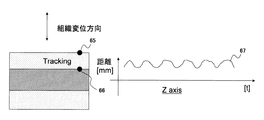
- tracking points 65 and 66 are set in the generated tomographic image.
- the tracking point may be set by, for example, displaying a tomographic image on the image display 26 and setting by the inspector via the interface unit 42, or by arbitrarily setting a plurality of tracking points on the tomographic image. You may comprise so that it may be set.
- these tracking points 65 and 66 are tracked using various methods such as a block matching method by the displacement measuring unit 30 or the like, for example, and a movement destination is obtained.
- the tissue displacement detector 51 measures the displacement of the distance in the direction corresponding to the displacement direction of the tissue between the tracking points 65 and 66.
- the case where the tissue is displaced in the vertical direction is taken as an example, and in this case, the displacement measurement value 67 periodically changes as shown on the right side of FIG.
- the tissue displacement detector 51 can detect the displacement of the tissue at the tomographic site by detecting this periodic change.
- two tracking points are set.
- three or more tracking points are set, and the displacement of the distance between these two arbitrary points is measured, and the measured value of the displacement is measured. Changes may be detected periodically.
- one tracking point is set, and periodic changes in the direction corresponding to the displacement direction of the tissue at the position of the tracking point are detected. It is also possible to detect the displacement.
- This embodiment is particularly effective when it is easier to obtain a stable elastic image by using the movement of a tissue or body in which changes in internal pressure such as the heart and blood vessels occur.
- the probe position is fixed and the probe position does not move, but it corresponds to the tissue displacement direction of the tracking point on the tomographic image. If the direction displacement is periodic, it is effective because it can be detected that the tissue of the tomographic site is displaced.
- the cross-correlation calculation of the pair of RF signal frame data 70 and 71 selected by the RF frame data selection unit 28 is performed by the displacement measurement unit 30 having a function as a correlation calculation unit. And input to the tissue displacement detector.
- the tissue displacement detector 51 detects the displacement of the tissue at the tomographic site based on the calculated correlation coefficient (correlation value). That is, the tissue displacement detection unit 51 monitors the correlation coefficient output from the correlation calculation unit, and when the correlation coefficient becomes larger than a preset threshold as shown on the right side of FIG. Detect tissue displacement.
- the correlation coefficient of the pair of RF signal frame data is relatively low, but the probe When generating an elasticity image while performing compression / release operations on the subject, or when generating an elasticity image using pressure changes due to the pulsation of the subject, the correlation value is relatively high Is to be used. In other words, for example, when moderate compression is obtained or when moderate displacement can be detected, the degree of correlation between the RF signal frame data increases. By detecting this, the tissue at the tomographic site is displaced. And that the elasticity image is acquired.
- the pair of RF signal frame data almost match and the correlation coefficient Indicates an upper limit (for example, 1.0), and in such a case, it can be appropriately excluded from detection of tissue displacement.
- tissue displacement detection when an elastic image is generated by performing a compression / release operation on a subject using a probe, or a pressure change is periodically applied to a tissue due to, for example, pulsation of the subject. This is an example applied to any of the cases where an elastic image is generated using.
- the tissue displacement detection unit 51 takes in the measurement value of the pressure measurement unit 46 and measures the pressure measurement value 73 as shown in FIG. The displacement of the tissue at the fault site is detected by the periodic change of.
- the displacement of the tissue is automatically detected by the ultrasonic diagnostic apparatus to detect the acquisition of the elastic image, but is not limited thereto.
- the inspector manually acquires the elasticity image via the ultrasonic probe 12 or the interface unit 42 with reference to the image display 26 in real time while taking the elasticity image. Is an example of instructing.
- the tissue displacement detection unit 51 detects that an elastic image has been acquired by a signal input via the ultrasonic probe 12 or the interface unit.
- a button-shaped tissue displacement detection switch 74 that can be pushed down by the examiner is provided.
- the examiner operates the tissue displacement detection switch 74 by depressing the tissue displacement detection switch 74 when it is determined that an appropriate elastic image is generated by appropriate compression while referring to the image display 26.
- the tissue displacement detection unit 51 receives a signal resulting from this push-down operation, and detects that the tissue displacement and elasticity image of the tomographic site have been acquired.
- the tissue displacement detection switch is not limited to the button switch, but may be any switch that can be arbitrarily operated by the examiner.
- a voice receiver such as a microphone is provided as the interface unit 42, and it is possible to detect that an elastic image has been acquired by instructing acquisition of the elastic image using this.
- a predetermined phrase audio signal is recorded in the memory, and the tissue displacement detection unit 51 uses a pattern recognition between the audio signal received by the microphone and the recorded audio signal to record the audio signal. It is detected that the displacement of the tissue at the tomographic site and the detected elastic image are acquired when the corresponding audio signal, such as matching or similar to the received audio signal, is received by the microphone.
- the tissue displacement detector 51 detects the displacement of the tissue at the tomographic site by any one of the modes as described above or by appropriately combining them. After the displacement of the tissue at the tomographic site is detected, a simulated living body image and a simulation superimposed on the living body simulated image on the image display 26 by the mark creating unit 52, the living body simulated image constructing unit 54, and the like that function as simulated image display means A mark is displayed.
- the present embodiment is an example in which an elastic image acquisition mark indicating a tomographic site from which an elastic image has been acquired is superimposed and displayed on a living body simulation image.
- a case where an image simulating the breast of a subject is applied as a living body simulation image is shown.
- ultrasound is transmitted and received while performing a probe operation (S75), and processing of ultrasonic images such as tomographic images and elastic images is performed as described above. (S76) These images are displayed (S77).
- the living body simulated image construction unit 54 obtains the elasticity image acquisition mark generated by the mark creation unit 52 and the tomographic position information and elasticity image of the subject from which the elasticity image stored in the memory 56 is acquired. Using the obtained information such as the output transition of the pressure measuring unit 46 as appropriate, a living body simulation image is constructed by superimposing an elastic image acquisition mark at a corresponding position on the living body simulation image (S81). As a result, the ultrasound image and the living body simulation image on which the simulation mark is superimposed are appropriately combined and displayed on the image display.
- an elastic image acquisition mark 86 indicating a tomographic part from which the elastic image has been acquired is displayed at a corresponding position on the biological simulation image 85, as shown in FIG. Are superimposed and displayed.
- the elastic image acquisition mark 86 includes information on the scanning position and orientation of the ultrasonic probe.
- an inspector who performs ultrasonic imaging can visually check at which position of the subject the elastic image has been acquired by referring to the living body simulated image.
- the living body simulation image 85 on which the elastic image acquisition mark 86 is superimposed is stored in the memory, a diagnostician or the like who makes a diagnosis with reference to the stored image visually refers to the living body simulation image. It can be confirmed at which position of the specimen the elasticity image was acquired.
- the elastic image acquisition marks 86 may be displayed one by one in real time, or as shown on the right side of the figure.
- the elastic image acquisition mark 86 superimposed in the past on the biological simulated image is left, and the mark may be sequentially superimposed and displayed on the biological simulated image. According to this, since the part where the elasticity image of the subject is acquired can be grasped at a glance, it is possible to prevent the image from being missed or to avoid wasteful imaging of the same part. .
- the coordinate calculation unit 50 aligns the coordinate system of the three-dimensional coordinates detected by the position information sensor with the coordinate system of the subject while ultrasonically imaging a specific part such as the nipple of the subject. Thereby, the ultrasonic imaging position on the living body simulation image can be specified.
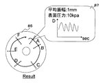
- FIG. 9 shows a state in which the inspector refers to the living body simulation image generated in the first embodiment of the display during the ultrasonic imaging, and after the inspection and recording in the memory, the examiner refers to the state. It is assumed that For example, when a diagnostician or the like selects an arbitrary elasticity image acquisition mark via an interface such as a mouse, keyboard, trackball, or screen touch sensor, a graph of the output transition of the pressure sensor associated with the selected mark, pressure A pressure state display 87 including the average amplitude of the pressure obtained from the output transition of the sensor and the average value of the pressure obtained from the output transition of the pressure sensor is made.
- an elastic image for example, when pressing with a probe, it is very important whether the compression is performed appropriately. If the degree of compression is different, a desired elastic image can be acquired. It becomes difficult.
- the diagnostician selects an elastic image acquisition mark of interest while referring to the biological simulated image once recorded in the memory, an elastic image is acquired at the tomographic location. It is possible to display the pressure conditions at the time. Therefore, it is possible to operate the probe so as to satisfy the same compression condition while referring to this. In this way, by providing multifaceted information to the diagnostician, the diagnostician can obtain an elastic image again with good reproducibility with reference to the displayed pressure conditions and the like. It may be used effectively.
- the selection of the elastic image acquisition mark is not limited to the input from the interface, but may be automatically set so as to be switched every set time.
- the elastic image Information obtained in the process of obtaining the information may be appropriately stored in a memory and displayed according to the selection of the mark. Further, a plurality of elastic image acquisition marks may be selected and a plurality of detailed information may be displayed, or graphs or the like may be superimposed and displayed.
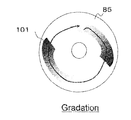
- the present embodiment is an example in which an elastic mark representing the hardness or softness of a set region in a tomographic site where an elastic image is acquired, that is, a tissue (tumor) of interest, is superimposed and displayed on a living body simulation image.
- ultrasound is transmitted and received while performing a probe operation (S90), and processing of ultrasonic images such as tomographic images and elastic images is performed as described above. (S91), these images are displayed (S92).
- the living body simulated image construction unit 54 includes the elasticity mark generated by the mark creation unit 52, the tomographic position information of the subject from which the elasticity image stored in the memory 56 is acquired, and the elasticity information of the tissue in the setting area of the elasticity image Using the information such as the output transition of the pressure measurement unit 46 obtained in the process of obtaining the elasticity image as appropriate, a simulated biological image is constructed by superimposing a simulated mark at a corresponding position on the simulated biological image (S96). ). As a result, the ultrasound image and the living body simulation image on which the simulation mark is superimposed are appropriately combined and displayed on the image display.
- the elastic marks 101 when the elastic image is acquired, the elastic marks 101 may be displayed one by one in real time, or the elastic marks 101 superimposed in the past on the living body simulated image are left. Alternatively, each time an elastic image is acquired, the marks may be sequentially superimposed and displayed on the biological simulated image. In this embodiment, an example of hue gradation is given. However, for example, the hardness or softness of the tissue may be displayed with gradation according to a numerical value or luminance.
- a simulation mark is superimposed and displayed on a living body simulation image, but may be displayed in association with a tomographic image or a part of an elasticity image.
- the elasticity mark 101 represents not the elasticity information of the entire acquired elasticity image but the elasticity information of the region of interest where the elasticity image is set, that is, the tissue of interest such as a tumor. Therefore, it is necessary to set a region of interest tissue from the elastic image.
- the tissue of interest such as a tumor shows low echo (low reflection level). That is, first, binarization processing is performed on the black and white tomographic image, and the position or distribution of the tumor is detected by setting a low echo area as a mask area.
- the tissue 112 in the mask region is cut out, and the elasticity information of the cut out tissue is averaged to create the elastic mark 101.
- the elastic mark need not be circular, and the shape can also be expressed and displayed using tumor distribution information.
- the subject can be referred to when the diagnostician refers to this. It is possible to easily determine which part of the eye should be examined in detail.
- the elastic mark is represented as a simple mark gradationized by, for example, hue or numerical value, a part that is relatively hard and may have a lesion tissue on the living body simulated image is seen at a glance. Can be grasped. Then, if necessary, it is possible to carry out a detailed examination by, for example, performing ultrasound imaging again, and determine a diagnosis and a treatment policy.
- the present embodiment is an example in which an elastic image that is a basis for generating the elastic mark is displayed via the elastic mark superimposed on the living body simulation image.
- the elasticity mark 101 is superimposed on the biological simulation image 85 and that the elasticity image corresponding to each elasticity mark is recorded in the memory in association with each elasticity mark 101.
- FIG. 13 shows the state in which the examiner refers to the simulated biological image generated in the third embodiment of the display during the ultrasonic imaging, or after being inspected and recorded in the memory, the examiner refers to the state. It is assumed that For example, when a diagnostician or the like selects an arbitrary elasticity image acquisition mark via an interface such as a mouse, keyboard, trackball, or screen touch sensor, the elasticity image associated with the selected mark is called from the memory and elastic. An image display 120 is made.
- the diagnostician for example, after the diagnostician is once recorded in the memory, if the elastic image acquisition mark of interest is selected while being displayed and referring to the living body simulation image, the elastic image at the tomographic point is referred to. can do. In this way, by providing information to the diagnostician from multiple angles, the diagnostician determines the overall tumor status of the subject while referring to the displayed living body simulation image and elasticity mark. On the other hand, it is possible to make a diagnosis or determine a treatment policy by calling an elastic image and referring to a point of interest in detail.
- the present embodiment is an example in which elastic marks are displayed in a gradation on a biological simulation image. That is, when the elastic mark is displayed, if it is detected at two or more locations, there is a high possibility that the objects inside are continuous. Therefore, as shown in FIG. 14, it is possible to express it with gradation by using information on the elasticity between two points and the distance between them.
- the examiner when the examiner conducts the examination and determines that the subject is a continuous object (tumor), the continuity can be displayed by expressing the two points with gradation. As a result, it can be reflected in the chart information without repeating the compression, which is effective in shortening the examination time.
- the present embodiment is an example in which only the elastic marks that are gradations within a threshold value range that is greater than or equal to a preset threshold value, or within a threshold value range are displayed. That is, for example, as shown in FIG. 15, by using an elastic scale bar 102 or the like, a threshold value is set in advance, or an examination person or a diagnosis person can arbitrarily set and adjust the examination. Only information necessary for the person / diagnostic can be displayed on the living body simulated image. It is also possible to automatically set this threshold value for each examination site.
- an elastic mark that is harder than a predetermined threshold value that is, a lesion may be necessary and a detailed examination is necessary, can be displayed.
- diagnosis and treatment policy can be determined. Since the display of the living body simulated image and the elasticity mark simply provides information such as the tissue elasticity of the subject to the examiner / diagnostic, it may not be practical even if there is too much information. In this case, the present embodiment is effective.
- an elastic mark is displayed on a living body simulation image generated in three dimensions. That is, as shown in FIG. 16 (a), on the living body simulated image 85 generated in three dimensions, the positional information of the tomographic part of the subject when the elastic image is acquired, and the surface of the tomographic part of the subject
- the elastic mark 101 can be superimposed and displayed in consideration of the depth information from.
- the compression mark 150 indicating the position of the contact surface of the ultrasonic probe with the subject when the elastic image is acquired may be displayed in an overlapping manner. Can do.
- the depth information from the ultrasonic transmission / reception unit in the medical chart as illustration information.
- it can be expressed in three dimensions as an elastic mark of the tumor, which is effective in that it is easy to grasp after examination.
- the compression mark 150 is provided on the body surface, and the elastic mark 101 is provided inside and displayed simultaneously, thereby making it possible to easily associate the relationship between the compression location and the image.
- This embodiment is an example in which a blood flow mark is superimposed and displayed on a living body simulation image in addition to a simulation mark, and blood flow information is obtained based on a reflected echo signal measured by an ultrasonic probe. It is presupposed that blood flow mark generation means for generating a blood flow mark that is graded according to the blood flow velocity of the tomographic site of the subject is provided.
- the speed or abundance of blood flow can be detected by a method using a known Doppler effect, and a blood flow mark gradated according to the detection result can be generated. Then, as shown in FIG. 17, the blood flow mark 160 can be made smaller than the elastic mark 101 and displayed on the elastic mark 101 together. In addition, a blood flow scale bar 161 indicating the speed of blood flow or the degree of abundance can be displayed.
- blood flow information and elasticity information can be simultaneously displayed on a living body simulated image and used as medical chart information to improve diagnosis accuracy and efficiency.
- the blood flow mark 160 can be easily recognized by distinguishing both, such as a star mark and the elastic mark 101 as a circle mark. Visibility can be improved by distinguishing between blood flow marks such as black and white gradation and elastic marks such as color gradation. Further, only the portion where the blood flow mark and the elasticity mark overlap may be displayed on the living body illustration.
- an ultrasonic inspection is performed after performing calibration and positioning with reference to a specific position of the subject such as a nipple. Then, as shown in FIG. 18, when the ultrasonic probe is moved to a location where an elastic image has been acquired in the past (if the position of the elastic mark 101 and the probe mark 170 indicating the probe position overlap each other) ), A display such as “PUSH” can be displayed on the image display 26 to prompt the examiner to perform an elastic image acquisition operation. At that time, elastic images acquired in the past may be displayed together.
- the burden on the inspector can be reduced and the efficiency of the inspection can be increased.
- the reproducibility can be improved by displaying the pressure condition when the elastic image is acquired.
- the present invention is not limited to the breast, and can be applied to places where ultrasonic image diagnosis is possible, such as the thyroid gland, liver, and prostate.
Abstract
La présente invention concerne un dispositif de diagnostic à ultrasons pouvant détecter une partie en coupe transversale d'un sujet dont l'image élastique est acquise et pouvant afficher ou enregistrer une image générée par la superposition de la partie en coupe transversale détectée sur une image simulée biologique. Un dispositif de diagnostic à ultrasons (1) comprend une unité de construction d'image élastique (34) permettant de générer l'image élastique d'une partie en coupe transversale sur la base d'une paire de données de trames de signaux RF acquises à des moments différents par l'émission/la réception d'ondes ultrasoniques à destination/en provenance d'un sujet (10), une unité de construction d'image simulée biologique (54) pour générer une image simulée biologique, un capteur d'informations de position (48) destiné à détecter la position de coordonnées tridimensionnelles et la posture d'une sonde à ultrasons, et une unité de calcul de coordonnées (50) pour la détection d'informations de position sur la partie en coupe transversale sur la base d'une sortie à partir du capteur d'informations de position. Ledit dispositif comprend en outre une unité de détection de déplacement de tissu (51) destinée à détecter le déplacement de tissu de la partie en coupe transversale. Ainsi, une marque d'acquisition d'image élastique peut être affichée ou enregistrée tout en étant superposée dans une position correspondante sur l'image simulée biologique sur la base des informations de position sur la partie en coupe transversale du sujet lorsque le déplacement du tissu est détecté par l'unité de détection de déplacement de tissu (51).
Applications Claiming Priority (2)
| Application Number | Priority Date | Filing Date | Title |
|---|---|---|---|
| JP2008028206A JP5156421B2 (ja) | 2008-02-07 | 2008-02-07 | 超音波診断装置 |
| JP2008-028206 | 2008-02-07 |
Publications (1)
| Publication Number | Publication Date |
|---|---|
| WO2009098973A1 true WO2009098973A1 (fr) | 2009-08-13 |
Family
ID=40952051
Family Applications (1)
| Application Number | Title | Priority Date | Filing Date |
|---|---|---|---|
| PCT/JP2009/051300 WO2009098973A1 (fr) | 2008-02-07 | 2009-01-28 | Dispositif de diagnostic à ultrasons |
Country Status (2)
| Country | Link |
|---|---|
| JP (1) | JP5156421B2 (fr) |
| WO (1) | WO2009098973A1 (fr) |
Cited By (5)
| Publication number | Priority date | Publication date | Assignee | Title |
|---|---|---|---|---|
| CN103118600A (zh) * | 2010-09-21 | 2013-05-22 | 株式会社日立医疗器械 | 超声波诊断装置以及超声波图像的显示方法 |
| CN103717145A (zh) * | 2011-07-27 | 2014-04-09 | 日立阿洛卡医疗株式会社 | 超声图像处理装置 |
| CN104224233A (zh) * | 2014-09-16 | 2014-12-24 | 无锡海斯凯尔医学技术有限公司 | 影像引导型弹性检测系统及其检测方法 |
| WO2018051265A1 (fr) * | 2016-09-15 | 2018-03-22 | Koninklijke Philips N.V. | Mesure et affichage de précharge élastographique ultrasonore |
| JP2019069319A (ja) * | 2019-02-08 | 2019-05-09 | 富士フイルム株式会社 | 硬さ導出装置、医用撮影システム、硬さ導出方法、及び硬さ導出プログラム |
Families Citing this family (5)
| Publication number | Priority date | Publication date | Assignee | Title |
|---|---|---|---|---|
| JP5535574B2 (ja) * | 2009-10-23 | 2014-07-02 | ジーイー・メディカル・システムズ・グローバル・テクノロジー・カンパニー・エルエルシー | 超音波診断装置 |
| JP5787286B2 (ja) * | 2010-05-31 | 2015-09-30 | 国立研究開発法人産業技術総合研究所 | 超音波生体組織測定装置 |
| KR101786008B1 (ko) | 2011-04-15 | 2017-10-16 | 알피니언메디칼시스템 주식회사 | 움직임 추적을 이용한 초음파 치료 장치와 그를 위한 방법 |
| KR20120117510A (ko) * | 2011-04-15 | 2012-10-24 | 알피니언메디칼시스템 주식회사 | 초음파 치료장치 및 그 장치의 구동 방법 |
| WO2022018942A1 (fr) * | 2020-07-21 | 2022-01-27 | 富士フイルム株式会社 | Dispositif, procédé et programme de traitement d'image médicale |
Citations (5)
| Publication number | Priority date | Publication date | Assignee | Title |
|---|---|---|---|---|
| JPH0428354A (ja) * | 1990-05-25 | 1992-01-30 | Toshiba Corp | 超音波診断装置 |
| JP2004089362A (ja) * | 2002-08-30 | 2004-03-25 | Hitachi Medical Corp | 超音波診断装置 |
| WO2006022238A1 (fr) * | 2004-08-25 | 2006-03-02 | Hitachi Medical Corporation | Dispositif echographique |
| WO2006054635A1 (fr) * | 2004-11-17 | 2006-05-26 | Hitachi Medical Corporation | Ultrasonographe et méthode d’affichage d’image par ultrason |
| JP2007029456A (ja) * | 2005-07-27 | 2007-02-08 | Matsushita Electric Ind Co Ltd | 超音波診断装置 |
Family Cites Families (2)
| Publication number | Priority date | Publication date | Assignee | Title |
|---|---|---|---|---|
| WO2008010500A1 (fr) * | 2006-07-18 | 2008-01-24 | Hitachi Medical Corporation | Dispositif de diagnostic à ultrasons |
| JP5199690B2 (ja) * | 2008-02-07 | 2013-05-15 | 株式会社日立メディコ | 超音波診断装置 |
-
2008
- 2008-02-07 JP JP2008028206A patent/JP5156421B2/ja not_active Expired - Fee Related
-
2009
- 2009-01-28 WO PCT/JP2009/051300 patent/WO2009098973A1/fr active Application Filing
Patent Citations (5)
| Publication number | Priority date | Publication date | Assignee | Title |
|---|---|---|---|---|
| JPH0428354A (ja) * | 1990-05-25 | 1992-01-30 | Toshiba Corp | 超音波診断装置 |
| JP2004089362A (ja) * | 2002-08-30 | 2004-03-25 | Hitachi Medical Corp | 超音波診断装置 |
| WO2006022238A1 (fr) * | 2004-08-25 | 2006-03-02 | Hitachi Medical Corporation | Dispositif echographique |
| WO2006054635A1 (fr) * | 2004-11-17 | 2006-05-26 | Hitachi Medical Corporation | Ultrasonographe et méthode d’affichage d’image par ultrason |
| JP2007029456A (ja) * | 2005-07-27 | 2007-02-08 | Matsushita Electric Ind Co Ltd | 超音波診断装置 |
Cited By (7)
| Publication number | Priority date | Publication date | Assignee | Title |
|---|---|---|---|---|
| CN103118600A (zh) * | 2010-09-21 | 2013-05-22 | 株式会社日立医疗器械 | 超声波诊断装置以及超声波图像的显示方法 |
| CN103717145A (zh) * | 2011-07-27 | 2014-04-09 | 日立阿洛卡医疗株式会社 | 超声图像处理装置 |
| US9349190B2 (en) | 2011-07-27 | 2016-05-24 | Hitachi Aloka Medical, Ltd. | Ultrasound image processing apparatus |
| CN104224233A (zh) * | 2014-09-16 | 2014-12-24 | 无锡海斯凯尔医学技术有限公司 | 影像引导型弹性检测系统及其检测方法 |
| CN104224233B (zh) * | 2014-09-16 | 2017-05-24 | 无锡海斯凯尔医学技术有限公司 | 影像引导型弹性检测系统及其检测方法 |
| WO2018051265A1 (fr) * | 2016-09-15 | 2018-03-22 | Koninklijke Philips N.V. | Mesure et affichage de précharge élastographique ultrasonore |
| JP2019069319A (ja) * | 2019-02-08 | 2019-05-09 | 富士フイルム株式会社 | 硬さ導出装置、医用撮影システム、硬さ導出方法、及び硬さ導出プログラム |
Also Published As
| Publication number | Publication date |
|---|---|
| JP2009183566A (ja) | 2009-08-20 |
| JP5156421B2 (ja) | 2013-03-06 |
Similar Documents
| Publication | Publication Date | Title |
|---|---|---|
| JP5199690B2 (ja) | 超音波診断装置 | |
| JP5156421B2 (ja) | 超音波診断装置 | |
| JP4817374B2 (ja) | 超音波診断装置 | |
| JP5479353B2 (ja) | 超音波診断装置 | |
| JP5559788B2 (ja) | 超音波診断装置 | |
| JP5689073B2 (ja) | 超音波診断装置、及び3次元弾性比算出方法 | |
| JP3932482B2 (ja) | 超音波診断装置 | |
| JP5087341B2 (ja) | 超音波診断装置 | |
| JP5437820B2 (ja) | 超音波診断装置、超音波画像処理方法 | |
| JP4989262B2 (ja) | 医用画像診断装置 | |
| JP6063454B2 (ja) | 超音波診断装置及び軌跡表示方法 | |
| JP2007282932A (ja) | 弾性画像生成方法及び超音波診断装置 | |
| JP5647990B2 (ja) | 超音波診断装置及び画像構成方法 | |
| JP5074097B2 (ja) | 超音波診断装置 | |
| JP5016911B2 (ja) | 超音波診断装置 | |
| JP5473527B2 (ja) | 超音波診断装置 | |
| JP4515799B2 (ja) | 超音波診断装置 | |
| JP4889540B2 (ja) | 超音波診断装置 | |
| JP5623609B2 (ja) | 超音波診断装置 | |
| JP6230801B2 (ja) | 超音波撮像装置及び超音波画像表示方法 | |
| JP4615528B2 (ja) | 超音波診断装置 | |
| JP2011167330A (ja) | 超音波診断装置 |
Legal Events
| Date | Code | Title | Description |
|---|---|---|---|
| 121 | Ep: the epo has been informed by wipo that ep was designated in this application |
Ref document number: 09708961 Country of ref document: EP Kind code of ref document: A1 |
|
| NENP | Non-entry into the national phase |
Ref country code: DE |
|
| 122 | Ep: pct application non-entry in european phase |
Ref document number: 09708961 Country of ref document: EP Kind code of ref document: A1 |