WO2009098799A1 - 超音波振動子 - Google Patents
超音波振動子 Download PDFInfo
- Publication number
- WO2009098799A1 WO2009098799A1 PCT/JP2008/067605 JP2008067605W WO2009098799A1 WO 2009098799 A1 WO2009098799 A1 WO 2009098799A1 JP 2008067605 W JP2008067605 W JP 2008067605W WO 2009098799 A1 WO2009098799 A1 WO 2009098799A1
- Authority
- WO
- WIPO (PCT)
- Prior art keywords
- thermal expansion
- piezoelectric element
- vibrator
- ultrasonic transducer
- mandrel
- Prior art date
- Legal status (The legal status is an assumption and is not a legal conclusion. Google has not performed a legal analysis and makes no representation as to the accuracy of the status listed.)
- Ceased
Links
Images



Classifications
-
- B—PERFORMING OPERATIONS; TRANSPORTING
- B06—GENERATING OR TRANSMITTING MECHANICAL VIBRATIONS IN GENERAL
- B06B—METHODS OR APPARATUS FOR GENERATING OR TRANSMITTING MECHANICAL VIBRATIONS OF INFRASONIC, SONIC, OR ULTRASONIC FREQUENCY, e.g. FOR PERFORMING MECHANICAL WORK IN GENERAL
- B06B1/00—Methods or apparatus for generating mechanical vibrations of infrasonic, sonic, or ultrasonic frequency
- B06B1/02—Methods or apparatus for generating mechanical vibrations of infrasonic, sonic, or ultrasonic frequency making use of electrical energy
- B06B1/06—Methods or apparatus for generating mechanical vibrations of infrasonic, sonic, or ultrasonic frequency making use of electrical energy operating with piezoelectric effect or with electrostriction
- B06B1/0607—Methods or apparatus for generating mechanical vibrations of infrasonic, sonic, or ultrasonic frequency making use of electrical energy operating with piezoelectric effect or with electrostriction using multiple elements
- B06B1/0611—Methods or apparatus for generating mechanical vibrations of infrasonic, sonic, or ultrasonic frequency making use of electrical energy operating with piezoelectric effect or with electrostriction using multiple elements in a pile
- B06B1/0618—Methods or apparatus for generating mechanical vibrations of infrasonic, sonic, or ultrasonic frequency making use of electrical energy operating with piezoelectric effect or with electrostriction using multiple elements in a pile of piezo- and non-piezoelectric elements, e.g. 'Tonpilz'
Definitions
- the present invention relates to the structure of an ultrasonic transducer.
- a wire bonding apparatus for connecting a pad of a semiconductor chip and a lead of a lead frame with a thin metal wire is used.
- a method in which a bonding tool is vibrated by ultrasonic vibration when a wire is pressed against a pad or a lead by a bonding tool is often used.
- the wire bonding apparatus is provided with an ultrasonic vibrator for vibrating the bonding tool.
- the ultrasonic transducer is used not only in the bonding apparatus but also in various devices using ultrasonic waves.
- a Langevin type ultrasonic transducer is often used in which piezoelectric elements are stacked coaxially on a mandrel of both screw bolts and tightened with nuts from both sides to compress the piezoelectric elements.
- the thermal expansion coefficient of the piezoelectric element is often smaller than the thermal expansion coefficient of the metal screw bolt used for the mandrel, and bolts and nuts are used so that a predetermined pressure is applied to the piezoelectric element in the initial assembly. Even when assembled, the applied pressure decreases due to the difference in thermal expansion when the temperature rises, and the applied pressure increases when the temperature decreases. There was a problem that the vibration would be reduced.
- Patent Document 1 a step portion having a diameter larger than that of the screw portion is provided on the inner surface between the contact portion of the nut screwed into the screw screw bolt and the screw portion, and the material of the nut is the screw screw. It is composed of materials having different thermal expansion coefficients, and by appropriately selecting the length of the nut step in consideration of the thermal expansion coefficient of both screw bolts, the thermal expansion coefficient of the piezoelectric element, and the thermal expansion coefficient of the nut, A method has been proposed in which a difference in thermal expansion with respect to a temperature change between a bolt and a laminated piezoelectric element is absorbed, and a change in pressure applied to the piezoelectric element due to a temperature change is reduced.
- Patent Document 1 since the method described in Patent Document 1 needs to have a different coefficient of thermal expansion from that of the nut and the bolt, the change in the pressure applied to the piezoelectric element can be reduced. Thermal stress due to the difference in thermal expansion coefficient between the bolt and the nut is generated in the threaded portion. And, if it is attempted to reduce the change in the applied pressure of the piezoelectric element while reducing the thermal stress generated in the threaded portion, it is necessary to increase the length of the stepped portion of the nut, resulting in an increase in the size of the ultrasonic vibrator. In order to make the whole compact, it is necessary to select a material that increases the difference between the thermal expansion coefficient of the nut and the thermal expansion coefficient of both screw bolts. There was a problem of becoming.
- the threaded portion when the thermal stress generated in the threaded portion increases, the threaded portion may be damaged due to metal fatigue when used for a long time.
- the deformation generated by the thermal stress may cause a minute deformation on the contact surface of the nut with the piezoelectric element, resulting in an increase in the impedance of the ultrasonic vibration, which may reduce the vibration.
- An object of the present invention is to reduce a change in pressure applied to a piezoelectric element due to a temperature change effectively in a stable structure in an ultrasonic vibrator.
- An ultrasonic transducer is an ultrasonic transducer comprising a plurality of piezoelectric elements stacked in the thickness direction and a compression mechanism that compresses the stacked piezoelectric elements. It has a thermal expansion difference absorber provided between the mechanism and absorbing the thermal expansion difference in the compression direction between the compression mechanism and the piezoelectric element.
- the ultrasonic vibrator is a mandrel-integrated Langevin type vibrator in which a mandrel in which piezoelectric elements are coaxially stacked and a vibrator main body having a larger outer shape than the mandrel are integrally configured
- the compression mechanism is a pressurizing nut that has a thermal expansion coefficient substantially the same as that of the mandrel at the end of the mandrel and is screwed into the screw to compress the piezoelectric element with the vibrator body.
- the body is laminated and compressed on the mandrel coaxially with the piezoelectric element, and has a coefficient of thermal expansion and a thickness that can absorb the difference in axial thermal expansion between the mandrel and the piezoelectric element.
- the ultrasonic transducer includes a transducer main body provided with an internal space extending in the axial direction, and a piezoelectric element built-in type vibration including a piezoelectric element laminated in the axial direction in the internal space.
- the compression mechanism includes a screw portion provided at one end of the vibrator body and a thermal expansion coefficient substantially the same as that of the vibrator body.
- a compression bolt that compresses, and the thermal expansion absorber is laminated and compressed together with the piezoelectric element in the internal space, and has a thermal expansion coefficient that can absorb the difference in axial thermal expansion between the vibrator body and the piezoelectric element. It is also preferable to have a thickness.
- the ultrasonic transducer has a built-in piezoelectric element including a transducer main body provided with an opening extending in the axial direction, and a piezoelectric element stacked and fitted in the opening in the axial direction.
- the compression mechanism is a plurality of taper members inserted between the piezoelectric elements.
- the sound velocity propagating through the transducer main body and the sound velocity propagating through the thermal expansion absorber are substantially the same.
- the present invention has an effect that, in an ultrasonic vibrator, a change in pressure applied to the piezoelectric element due to a temperature change can be effectively reduced with a stable structure.
- an ultrasonic vibrator 10 attached to an ultrasonic horn 30 for wire bonding includes a columnar vibrator body 11 and a cylinder having a diameter smaller than that of the vibrator body 11.
- An electrode plate 15 having an inner diameter and a thickness smaller than that of the piezoelectric element 14, a back body 16 which is a thermal expansion absorber having substantially the same outer diameter and inner diameter as the piezoelectric element 14, and a mandrel 12 is a mandrel-integrated Langevin type vibrator including a threaded portion 13 provided at an end of 12 and a pressurizing nut 17 screwed into the threaded portion 13.
- the plurality of piezoelectric elements 14 and the electrode plates 15 are alternately stacked so that the center hole enters the mandrel 12 and is coaxial with the mandrel 12.
- the back body 16 is laminated so as to be coaxial with the mandrel 12 on the opposite side of the vibrator body 11 between the laminated piezoelectric element 14 and electrode plate 15.
- the pressurizing nut 17 is screwed into a screw portion 13 provided at the end of the mandrel, and the piezoelectric elements 14, the electrode plates 15, and the back body 16 which are laminated coaxially with the mandrel 12 are connected to the vibrator body 11. It compresses between them and gives the necessary pressure as an ultrasonic vibrator.
- the vibrator body 11 is connected to an ultrasonic horn 30 having a capillary 31 as a bonding tool attached at the tip and a fixing flange 32 provided in the middle.
- the ultrasonic horn 30 and the vibrator main body 11 may be manufactured by integral molding, or may be configured to be connected by a connecting member such as a bolt.
- the ultrasonic vibration generated by the ultrasonic vibrator 10 during bonding causes the capillary 31 to vibrate via the ultrasonic horn 30.
- the vibrator body 11 and the mandrel 12 are made of, for example, titanium, and the pressurizing nut 17 is made of titanium similar to that of the mandrel 12 or a titanium alloy having a thermal expansion coefficient substantially the same as that of the mandrel 12.
- the element 14 is made of lead zirconate titanate (PZT), and the electrode plate 15 is made of a copper plate.
- the back body 16 for example, duralumin, austenitic stainless steel, high-tensile steel or the like is used.
- the piezoelectric element 14, the electrode plate 15, and the back body 16 are laminated on the mandrel 12, the thickness of the piezoelectric element 14 is d, the thickness of the electrode plate 15 is b, The laminated thickness with the electrode plate 15 is L1. Further, if the thickness of the back body 16 is L2, and the length of the mandrel 12 where the piezoelectric element 14, the electrode plate 15 and the back body 16 are laminated is L3, the amount of thermal expansion of each part due to temperature change Are ⁇ L1, ⁇ L2, and ⁇ L3, respectively. When the temperature of the ultrasonic transducer 10 changes, the thermal expansion amounts ⁇ L1, ⁇ L2, and ⁇ L3 also change.
- the thermal expansion of the mandrel 12 is achieved.
- the amount ⁇ L3 is larger than the thermal expansion amount ⁇ L1 of the laminated portion of the piezoelectric element 14 and the electrode plate 15. Therefore, the difference ⁇ L3 ⁇ L1 is canceled by the thermal expansion amount of the back body 16. That is, the following equation 1 is set so that the thermal expansion amount ⁇ L2 of the back body 16 is equal to ⁇ L3 ⁇ L1.
- ⁇ L2 ⁇ L3 ⁇ L1 (Formula 1)
- the thermal expansion coefficient of the back body 16 is ⁇ x
- the thickness of one piezoelectric element 14 is d
- the thermal expansion coefficient is ⁇ d
- the thickness of one electrode plate 15 is b
- the thermal expansion coefficient is ⁇ b.
- the thermal expansion amount canceling required thickness Lx of the back body 16 can be expressed as the following Expression 2.
- Lx N ⁇ (b ⁇ ⁇ b + d ⁇ ⁇ d ⁇ d ⁇ ⁇ a ⁇ b ⁇ ⁇ a) / ( ⁇ a ⁇ x) (Formula 2)
- N 4
- the required thickness Lx of the back body 16 for canceling the thermal expansion amount is about 1.78 mm.
- the necessary thickness Lx for canceling the thermal expansion amount of the back body 16 is about 3.2 mm.
- the mandrel 12, the piezoelectric element 14, and the electrode plate are used by the back body 16.
- a heat source such as a motor or a heater of the bonding apparatus
- the mandrel 12, the piezoelectric element 14, and the electrode plate are used by the back body 16.
- the thermal expansion difference between 15 laminated bodies can be canceled.
- fluctuations in the pressure applied to the piezoelectric element due to the ambient temperature and reduction of ultrasonic vibration due to an increase in impedance can be suppressed, so that the capillary 31 can be vibrated stably and good bonding quality is maintained. There is an effect that can be done.
- the mandrel 12 and the pressurizing nut 17 are made of a material having substantially the same thermal expansion coefficient. Therefore, the thread of the screw portion 13 provided at the end of the mandrel 12 and the pressurizing nut 17 There is almost no thermal stress due to the difference in thermal expansion between the nut 17 and the thread groove, and the screw portion 13 can be prevented from being damaged. In particular, even when vibration due to an impact force during bonding is transmitted to the pressurizing nut 17 and the screw portion 13 for a long time, there is an effect that damage to the screw portion 13 can be suppressed.
- the thermal stress in the threaded portion 13 can be reduced, even when the temperature of the ultrasonic vibrator 10 changes, the deformation of the surface 18 in contact with the back body 16 of the pressurizing nut 17 can be suppressed. It is possible to suppress an increase in impedance of ultrasonic vibrations and a reduction in vibrations, and it is possible to continue good bonding.
- the vibrator body 11 is made of titanium having a sound velocity of about 5000 m / s propagating through the vibrator body 11.
- duralumin, austenitic stainless steel, or high-tensile steel is used for the back body 16
- the speed of sound propagating inside each material is approximately 4000 to 5200 m / s, which is close to the speed of sound propagating inside the vibrator body 11. ing.
- the back body 16 can obtain a uniform ultrasonic vibration, without attenuating an ultrasonic vibration.
- the back body 16 is made of duralumin, the size is small and the specific gravity thereof is small. Therefore, the ultrasonic vibrator 10 can be reduced in weight, and the effect of corresponding to high-speed bonding can be achieved.
- an ultrasonic transducer 100 with a built-in piezoelectric element for wire bonding includes a transducer main body 50 extending in the axial direction, and a rectangular opening provided in the center of the transducer main body 50 in the axial direction. 42, a piezoelectric element 44 that is stacked and fitted in the opening 42 in the axial direction, a thin metal electrode plate 45 that is stacked together with the piezoelectric element 44, and the first and second electrodes that are inserted between the piezoelectric elements 44.
- the vibrator body 50 has a capillary 51 as a bonding tool attached to the tip thereof, and flanges 52 for fixing the vibrator body 50 are provided on both sides thereof.
- the opening 42 penetrates the vibrator body 50 in the vertical direction, and the first and second taper members 47 and 48 are arranged at the center thereof, and the first taper member 47 and the opening 42 are arranged.
- a piezoelectric element 44 and an electrode plate 45 are stacked between the two wall surfaces.
- the first taper member 47 has a wedge shape with a tip that becomes thinner upward
- the second taper member 48 has a wedge shape with a tip that becomes narrower downward.
- the taper angle of each of the taper members 47 and 48 is as follows. When the two first taper members 47 and the second taper member 48 are combined, the respective outer surfaces of the first taper member 47 are at an angle.
- each piezoelectric element 44 and the electrode plate 45 are placed between the first taper member 47 and the wall of the opening 42.
- the piezoelectric element 44 is configured to be compressed so that a predetermined pressure is applied.
- the vibrator body 50 is made of, for example, titanium, the taper members 47 and 48 are made of the same titanium as the vibrator body 50, the piezoelectric element 44 is made of lead zirconate titanate (PZT),
- the electrode plate 15 is made of a copper plate.
- the back body 46 for example, duralumin, austenitic stainless steel, high tensile steel or the like is used.
- the thermal expansion coefficient of the back body 46 is ⁇ x
- the thickness of one piezoelectric element 44 is d
- the heat is the same as in the above-described embodiment.
- the expansion coefficient is ⁇ d
- the thickness of one electrode plate 45 is b
- the thermal expansion coefficient is ⁇ b
- the thermal expansion coefficient of the vibrator body 50 is ⁇ a
- the number of piezoelectric elements 44 and electrode plates 45 is N
- the thickness Lx required for canceling the thermal expansion amount of the back body 46 can be expressed by (Expression 2) shown above.
- the thermal expansion amount canceling required thickness Lx when various materials such as duralumin are used for the back body 46 is expressed by (Equation 2) similar to the above-described embodiment.
- the vibrator main body 50, the piezoelectric element 14, and the electrode are formed by the back body 46.
- the difference in thermal expansion between the laminated body of the plates 15 can be canceled, and there is an effect that good bonding quality can be maintained.
- the speed of sound propagating through the vibrator body 50, the back body 46, and the first and second taper members 47 and 48 is approximately 4000 to 5200 m / s, and It is close to the speed of sound propagating inside. For this reason, the back body 46 can obtain uniform ultrasonic vibration without attenuating the ultrasonic vibration, and there is an effect that good bonding can be continued.
- FIG. 5 is configured to press the piezoelectric element of the ultrasonic transducer 100 with a built-in piezoelectric element described with reference to FIGS. 3 and 4 by screwing a pressing block 68.
- the piezoelectric element built-in type ultrasonic transducer 100 of the present embodiment includes a transducer body 60 extending in the axial direction and a cavity that is an internal space provided in the transducer body 60 in the axial direction.
- a piezoelectric element 64 laminated in the cavity 62 in the axial direction a piezoelectric element 64 laminated in the cavity 62 in the axial direction, a metal plate electrode plate 65 laminated together with the piezoelectric element 64, a back body 66 laminated together with the piezoelectric element 64 in the axial direction, and vibration And a pressing block 68 that is a pressurizing bolt screwed into a screw hole 67 provided at one end of the child main body 60.
- the pressing block 68 screwed into the screw hole 67 is configured to pressurize the laminated piezoelectric element 64, the electrode plate 65, and the back body 66 so as to give a necessary pressure as an ultrasonic vibrator.
- the vibrator body 60 provided with the screw hole 67 at one end is made of, for example, titanium, and the pressing block 68 screwed into the screw hole 67 is made of titanium similar to the vibrator body 60 or has a thermal expansion coefficient of the vibrator body. It is made of a titanium alloy that is substantially the same as 60.
- the piezoelectric element 64, the electrode plate 65, and the back body 66 are made of the same material as that of the above-described embodiment.
- the thermal expansion coefficient of the back body 66 is ⁇ x
- the thickness of one piezoelectric element 64 is d
- the heat is the same as in the embodiment described above. If the expansion coefficient is ⁇ d, the thickness of one electrode plate 65 is b, the thermal expansion coefficient is ⁇ b, the thermal expansion coefficient of the vibrator body 60 is ⁇ a, and the number of piezoelectric elements 64 and electrode plates 65 is N
- the required thermal expansion amount canceling thickness Lx when various materials such as duralumin are used for the back body 66 is expressed by (Equation 2) similar to the above-described embodiment. Moreover, this embodiment has the same effect as the embodiment described above.
- each embodiment of the present invention has described an example in which the present invention is applied to an ultrasonic transducer for wire bonding.
- the present invention is not limited to an ultrasonic transducer for wire bonding, and uses ultrasonic vibration.
- the present invention can be widely applied to instruments, devices, etc.
Landscapes
- Engineering & Computer Science (AREA)
- Mechanical Engineering (AREA)
- Transducers For Ultrasonic Waves (AREA)
- Apparatuses For Generation Of Mechanical Vibrations (AREA)
Abstract
超音波振動子において、圧電素子(14)が同軸に積層される心棒(12)と振動子本体(11)とが一体に構成された心棒一体型ランジュバン型振動子の超音波振動子(10)と、心棒端部のねじ部(13)と、心棒(12)と実質同一の熱膨張係数を備え、ねじ部(13)にねじ込まれ圧電素子(14)を振動子本体(11)との間で圧縮する与圧用ナット(17)を含む圧縮機構と、圧電素子(14)と同軸に心棒に積層圧縮され、心棒(12)と圧電素子(14)との軸方向の熱膨張の差を吸収することのできる熱膨張係数と厚さを有する背面体(16)を備える。これによって、安定した構造で効果的に温度変化による圧電素子の与圧力の変化を低減することができる。
Description
本発明は、超音波振動子の構造に関する。
半導体装置の製造では、半導体チップのパッドとリードフレームのリードを金属細線のワイヤで接続するワイヤボンディング装置が用いられている。このようなワイヤボンディング装置では、ボンディングツールによってワイヤをパッド或いはリードに圧着させる際にボンディングツールを超音波振動によって加振する方法が多く用いられている。そして、ワイヤボンディング装置にはボンディングツールを振動させるための超音波振動子が設けられている。また、超音波振動子はボンディング装置に限らず、超音波を利用した各種の機器にも用いられている。
このような超音波振動子としては、両ねじボルトの心棒に同軸に圧電素子を積層し、両側からナットで締め上げて圧電素子を圧縮するランジュバン型超音波振動子が用いられることが多い。しかし、圧電素子の熱膨張係数は、心棒に用いられる金属製の両ねじボルトの熱膨張係数よりも小さい場合が多く、初期の組立において圧電素子に所定の与圧力がかかるようにボルト、ナットを組み立てていても、温度が上昇すると熱膨張差によってその与圧力が低下し、温度が低下するとその与圧力が上昇するというように、周囲温度によって圧電素子への与圧力が変動し、インピーダンスの上昇によって振動が低減してしまうという問題があった。
そこで、特許文献1では、両ねじボルトにねじ込むナットの圧電素子との当たり面と、ねじ部との間の内面にねじ部よりも径の大きな段部を設け、ナットの材料を両ねじボルトと異なる熱膨張係数を持つ材料によって構成し、ナットの段部の長さを両ねじボルトの熱膨張係数と圧電素子の熱膨張係数とナットの熱膨張係数を考慮して適当に選択することによって、ボルトと積層された圧電素子との温度変化に対する熱膨張差を吸収させ、温度変化による圧電素子の与圧力の変化を低減する方法が提案されている。
しかし、特許文献1に記載された方法は、ナットとボルトとは異なる熱膨張係数を備えていることが必要となるので、圧電素子の与圧力の変化を低減することはできるものの、ボルトとナットのねじ部にはボルトとナットとの熱膨張係数の差による熱応力が発生してしまう。そして、ねじ部に発生する熱応力を低減しつつ圧電素子の与圧力の変化を低減しようとすると、ナットの段部長さを長くすることが必要となり、超音波振動子が大型化してしまうという問題があり、全体をコンパクトにまとめようとすると、ナットの熱膨張係数と両ねじボルトの熱膨張係数との差が大きくなるような材料を選択する必要があり、ねじ部の熱応力が大きなものとなってしまうという問題があった。特に、ねじ部に発生する熱応力が大きくなってくると、長時間使用した場合に、金属疲労によってねじ部が破損してしまうおそれがあった。また、熱応力によって発生する歪によってナットの圧電素子への当たり面に微小な変形が生じ、超音波振動のインピーダンスが上昇し、振動の低減を招く場合があった。
本発明は、超音波振動子において、安定した構造で効果的に温度変化による圧電素子の与圧力の変化を低減することを目的とする。
本発明の超音波振動子は、厚み方向に積層された複数の圧電素子と、積層された圧電素子を圧縮する圧縮機構と、を備える超音波振動子であって、積層された圧電素子と圧縮機構との間に設けられ、圧縮機構と圧電素子との間の圧縮方向の熱膨張差を吸収する熱膨張差吸収体を有すること、を特徴とする。
本発明の超音波振動子において、超音波振動子は、圧電素子が同軸に積層される心棒と心棒より外形の大きい振動子本体とが一体に構成された心棒一体型ランジュバン型振動子であり、圧縮機構は、心棒端部のねじ部と、心棒と実質同一の熱膨張係数を備え、ねじ部にねじ込まれて圧電素子を振動子本体との間で圧縮する与圧用ナットであり、熱膨張吸収体は、圧電素子と同軸に心棒に積層圧縮され、心棒と圧電素子との軸方向の熱膨張の差を吸収することのできる熱膨張係数と厚さとを有すること、としても好適である。
本発明の超音波振動子において、超音波振動子は、軸方向に延びる内部空間が設けられる振動子本体と、内部空間内に軸方向に積層された圧電素子と、を含む圧電素子内蔵型振動子であり、圧縮機構は、振動子本体の一端に設けられたねじ部と、振動子本体と実質同一の熱膨張係数を備え、ねじ部にねじ込まれて圧電素子を振動子本体との間で圧縮する与圧用ボルトであり、熱膨張吸収体は、内部空間内に圧電素子と共に積層圧縮され、振動子本体と圧電素子との軸方向の熱膨張の差を吸収することのできる熱膨張係数と厚さとを有すること、としても好適である。
本発明の超音波振動子において、超音波振動子は、軸方向に延びる開口が設けられる振動子本体と、開口内に軸方向に積層して嵌めこまれた圧電素子と、を含む圧電素子内蔵型振動子であり、圧縮機構は、圧電素子の間に差し込まれる複数のテーパ部材であること、としても好適である。
また、本発明の超音波振動子において、振動子本体の内部を伝搬する音速と熱膨張吸収体の内部を伝搬する音速とが略同一であることとしても好適である。
本発明は、超音波振動子において、安定した構造で効果的に温度変化による圧電素子の与圧力の変化を低減することができるという効果を奏する。
10 超音波振動子、11,50,60 振動子本体、12 心棒、13 ねじ部、14,44,64 圧電素子、15,45,65 電極板、16,46,66 背面体、17 与圧用ナット、18 面、30 超音波ホーン、31,51 キャピラリ、32,52 固定用フランジ、42 開口、47 第1のテーパ部材、48 第2のテーパ部材、62 空洞、67 ねじ孔、68 押圧ブロック、100 圧電素子内蔵型超音波振動子、b 電極板の厚さ、d 圧電素子の厚さ、Lx 背面体の熱膨張量キャンセル必要厚さ、N 圧電素子と電極板の積層枚数、αa 心棒及び振動子本体の熱膨張係数、αb 電極板の熱膨張係数、αd 圧電素子の熱膨張係数、αx 背面体の熱膨張係数。
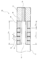
以下、本発明の好適な実施形態について、図面を参照しながら説明する。図1に示すように、ワイヤボンディング用の超音波ホーン30に取付けられる超音波振動子10は、円柱型の振動子本体11と、振動子本体11よりも直径が小さい円柱で振動子本体11と同軸で一体に設けられた心棒12と、振動子本体11と略同一の外径寸法で心棒12よりも大きな孔を備えるドーナツ状平板の圧電素子14と、圧電素子14と略同一の外径、内径寸法を有し、その厚さが圧電素子14よりも薄い電極板15と、圧電素子14と略同一の外径、内径寸法を有している熱膨張吸収体である背面体16と、心棒12の端部に設けられたねじ部13と、ねじ部13にねじ込まれる与圧用ナット17と、を含んでいる心棒一体型ランジュバン型振動子である。
複数の圧電素子14と電極板15とはその中心の孔が心棒12に入って心棒12と同軸となるように交互に積層されている。背面体16は積層された圧電素子14と電極板15との振動子本体11と反対側に心棒12と同軸となるように積層されている。与圧用ナット17は心棒の端部に設けられたねじ部13にねじ込まれ、心棒12と同軸に積層された各圧電素子14と、各電極板15と、背面体16を振動子本体11との間で圧縮し、超音波振動子として必要な与圧力を与えている。
振動子本体11は先端にボンディングツールであるキャピラリ31が取付けられ、中間に固定用フランジ32が設けられている超音波ホーン30に接続されている。超音波ホーン30と振動子本体11とは、一体成形によって製作されていてもよいし、ボルト等の接続部材で接続するよう構成されていてもよい。そして、ボンディングの際には超音波振動子10によって発生した超音波振動は超音波ホーン30を介してキャピラリ31を振動させる。
振動子本体11と心棒12とは、例えば、チタンなどによって製作され、与圧用ナット17は心棒12と同様のチタン或いは、熱膨張係数が心棒12と実質同一となるチタン合金などで製作され、圧電素子14はチタン酸ジルコン酸鉛(PZT)にて構成され、電極板15は銅板によって製作されている。また、背面体16としては、例えば、ジュラルミン或いは、オーステナイト系ステンレス鋼、高張力鋼等が用いられる。
図2に示すように、圧電素子14と電極板15と背面体16とは心棒12に積層されており、圧電素子14の厚さはd、電極板15の厚さはb、圧電素子14と電極板15との積層厚さはL1となっている。また、背面体16の厚さはL2で、圧電素子14と電極板15と背面体16とが積層されている部分の心棒12の長さをL3とすると、温度変化による各部分の熱膨張量は、それぞれΔL1、ΔL2、ΔL3、となる。超音波振動子10の温度が変化すると、各熱膨張量ΔL1、ΔL2、ΔL3も変化してくる。本実施形態の様に心棒12にチタンを用い、圧電素子14にチタン酸ジルコン酸鉛(PZT)を用い、電極板15には薄い銅板を用いているような場合には、心棒12の熱膨張量ΔL3は、圧電素子14と電極板15の積層部分の熱膨張量ΔL1よりも大きくなっている。そこでこの差のΔL3―ΔL1を背面体16の熱膨張量でキャンセルする。つまり、背面体16の熱膨張量ΔL2がΔL3―ΔL1に等しくなる様に次の式1のように設定する。
ΔL2=ΔL3―ΔL1 (式1)
ΔL2=ΔL3―ΔL1 (式1)
ここで、背面体16の熱膨張係数をαx、一枚の圧電素子14の厚さをd、その熱膨張係数をαd、一枚の電極板15の厚さをb、その熱膨張係数をαb、心棒12の熱膨張係数をαa、圧電素子14と電極板15の各枚数をNとすると、背面体16の熱膨張量キャンセル必要厚さLxは次の式2のように表すことができる。
Lx=N×(b×αb+d×αd-d×αa-b×αa)/(αa-αx) (式2)
Lx=N×(b×αb+d×αd-d×αa-b×αa)/(αa-αx) (式2)
例えば、振動子本体11及び心棒12が熱膨張係数αa=8×10⁻⁶のチタンで、圧電素子は厚さd=4mm、熱膨張係数αd=3×10⁻⁶のチタン酸ジルコン酸鉛(PZT)で、電極板15が厚さb=0.4mm、熱膨張係数αb=18×10-6の銅板で、圧電素子14、電極板15の積層数がN=4の場合、背面体16材質を熱膨張係数αx=23×10-6のジュラルミンとすると、背面体16の熱膨張量キャンセル必要厚さLxは約1.07mmとなる。また、背面体16の材質を熱膨張係数αx=17×10-6のオーステナイト系ステンレス鋼とすると、背面体16の熱膨張量キャンセル必要厚さLxは約1.78mmとなり、背面体16材質を熱膨張係数αx=13×10-6の高張力鋼とすると、背面体16の熱膨張量キャンセル必要厚さLxは約3.2mmとなる。
以上説明した、本実施形態では、ボンディング装置のモータ、ヒータなどの発熱源からの熱によって超音波振動子10の温度が変化した場合でも、背面体16によって心棒12と、圧電素子14と電極板15の積層体との間の熱膨張差をキャンセルすることができるという効果を奏する。また、周囲温度による圧電素子への与圧力の変動、インピーダンスの上昇による超音波振動の低減を抑制することができるので、キャピラリ31を安定して加振することができ、良好なボンディング品質を保持することができるという効果を奏する。また、本実施形態では、心棒12と与圧用ナット17は熱膨張係数が略同一となる材料で構成されていることから、心棒12の端部に設けられたねじ部13のねじ山と与圧用ナット17のねじ溝との間には熱膨張差による熱応力がほとんど発生せず、ねじ部13の損傷を防止することができるという効果を奏する。特にボンディングの際の衝撃力による振動が長時間にわたって与圧用ナット17とねじ部13とに伝わった場合でも、ねじ部13の損傷を抑制することができるという効果を奏する。
また、ねじ部13における熱応力が低減できることから、超音波振動子10の温度が変化した場合であっても、与圧用ナット17の背面体16に接する面18の変形を抑制することができ、超音波振動のインピーダンス上昇や振動の低減を抑制することができ、良好なボンディングを継続することができるという効果を奏する。
本実施形態では、振動子本体11はその内部を伝搬する音速が約5000m/sのチタンで構成されている。一方、背面体16にジュラルミン、オーステナイト系ステンレス鋼、高張力鋼を使用した場合、各材料の内部を伝搬する音速は略4000~5200m/sで振動子本体11の内部を伝搬する音速に近くなっている。このため、背面体16が超音波振動を減衰させたりすること無く、一様な超音波振動を得ることができるという効果を奏する。更に、背面体16をジュラルミンで構成した場合には、大きさも小さくその比重も小さいものとなることから、超音波振動子10を軽量化することができ、高速ボンディングに対応するという効果を奏する。
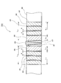
図3及び図4を参照しながら本発明の他の実施形態について説明する。図3に示すように、ワイヤボンディング用の圧電素子内蔵型超音波振動子100は、軸方向に延びる振動子本体50と、振動子本体50の中央部に設けられた軸方向に長い長方形の開口42と、開口42の中に軸方向に積層して嵌めこまれた圧電素子44と、圧電素子44と共に積層された金属薄板の電極板45と、圧電素子44の間に差し込まれる第1、第2のテーパ部材47,48と、第2のテーパ部材48と圧電素子44との間に設けられる熱膨張吸収体である背面体46とを備えている。また、振動子本体50はその先端にボンディングツールであるキャピラリ51が取付けられており、その側面には振動子本体50を固定するためのフランジ52が両側に設けられている。
図4に示すように、開口42は振動子本体50を上下方向に貫通しており、その中央に第1、第2のテーパ部材47,48が配置され、第1のテーパ部材47と開口42の壁面との間に圧電素子44と電極板45とが積層配置されている。第1のテーパ部材47は、上方向に向かって先端が薄くなるくさび型で、第2のテーパ部材48は下方に向かって先端が細くなるくさび型で、各テーパ部材47,48のテーパ角度は、二枚の第1のテーパ部材47と一枚の第2のテーパ部材48とを組み合わせた際に第1のテーパ部材47の各外側の面が平行となるような角度となっている。そして、第2のテーパ部材48を二枚の第1のテーパ部材47の間に差し込むことによって、各圧電素子44と電極板45とを第1のテーパ部材47と開口42の壁との間に圧縮して圧電素子44に所定の与圧力がかかるように構成されている。
振動子本体50は、例えば、チタンなどによって製作され、各テーパ部材47,48は振動子本体50と同一のチタンで製作され、圧電素子44はチタン酸ジルコン酸鉛(PZT)にて構成され、電極板15は銅板によって製作されている。また、背面体46としては、例えば、ジュラルミン或いは、オーステナイト系ステンレス鋼、高張力鋼等が用いられる。
このように構成された圧電素子内蔵型超音波振動子100において、先に説明した実施形態と同様、背面体46の熱膨張係数をαx、一枚の圧電素子44の厚さをd、その熱膨張係数をαd、一枚の電極板45の厚さをb、その熱膨張係数をαb、振動子本体50の熱膨張係数をαa、圧電素子44と電極板45の各枚数をNとすると、背面体46の熱膨張量キャンセル必要厚さLxは先に示した(式2)によって表すことができる。また、背面体46にジュラルミン等の各種材料を使用した場合の熱膨張量キャンセル必要厚さLxは先に説明した実施形態と同様の(式2)によって表される。
以上説明した、本実施形態では、ボンディング装置の発熱源からの熱で圧電素子内蔵型超音波振動子100の温度が変化した場合でも、背面体46によって、振動子本体50と圧電素子14と電極板15の積層体との間の熱膨張差をキャンセルすることができ、良好なボンディング品質を維持することができるという効果を奏する。また、先に説明した実施形態と同様、振動子本体50と背面体46及び第1、第2のテーパ部材47,48の内部を伝搬する音速は略4000~5200m/sで振動子本体50の内部を伝搬する音速に近くなっている。このため、背面体46が超音波振動を減衰させたりすること無く、一様な超音波振動を得ることができ、良好なボンディングを継続することができるという効果を奏する。
図5を参照しながら本発明の他の実施形態について説明する。図5は、図3、図4を参照して説明した圧電素子内蔵型超音波振動子100の圧電素子の加圧を、押圧ブロック68をねじ込むことによって行うように構成したものである。図5に示すように、本実施形態の圧電素子内蔵型超音波振動子100は、軸方向に延びる振動子本体60と、振動子本体60の内部に軸方向に設けられた内部空間である空洞62と、空洞62の中に軸方向に積層された圧電素子64と、圧電素子64と共に積層された金属薄板の電極板65と、圧電素子64と共に軸方向に積層された背面体66と、振動子本体60の一端に設けられたねじ孔67にねじ込まれる与圧用ボルトである押圧ブロック68と、を備えている。ねじ孔67にねじ込まれた押圧ブロック68は、積層された圧電素子64、電極板65、背面体66を加圧し超音波振動子として必要な与圧力を与える様構成されている。
一端にねじ孔67が設けられた振動子本体60は、例えば、チタンなどによって製作され、ねじ孔67にねじ込まれる押圧ブロック68は振動子本体60と同様のチタン或いは、熱膨張係数が振動子本体60と実質同一となるチタン合金などで製作されている。圧電素子64、電極板65、背面体66には先に説明した実施形態と同様の材料が用いられている。
このように構成された圧電素子内蔵型超音波振動子100において、先に説明した実施形態と同様、背面体66の熱膨張係数をαx、一枚の圧電素子64の厚さをd、その熱膨張係数をαd、一枚の電極板65の厚さをb、その熱膨張係数をαb、振動子本体60の熱膨張係数をαa、圧電素子64と電極板65の各枚数をNとすると、背面体66にジュラルミン等の各種材料を使用した場合の熱膨張量キャンセル必要厚さLxは先に説明した実施形態と同様の(式2)によって表される。また、本実施形態は、先に説明した実施形態と同様の効果を奏する。
以上、本発明の各実施形態は、本発明をワイヤボンディング用の超音波振動子に適用した例について説明したが、本発明はワイヤボンディング用の超音波振動子に限らず、超音波振動を利用した計器、機器などに広く適用することができる。
Claims (7)
- 超音波振動子であって、
厚み方向に積層された複数の圧電素子と、
積層された圧電素子を圧縮する圧縮機構と、
積層された圧電素子と圧縮機構との間に設けられ、圧縮機構と圧電素子との間の圧縮方向の熱膨張差を吸収する熱膨張差吸収体を有すること、
を特徴とする超音波振動子。 - 請求の範囲1に記載の超音波振動子であって、
超音波振動子は、圧電素子が同軸に積層される心棒と心棒より外形の大きい振動子本体とが一体に構成された心棒一体型ランジュバン型振動子であり、
圧縮機構は、心棒端部のねじ部と、心棒と実質同一の熱膨張係数を備え、ねじ部にねじ込まれて圧電素子を振動子本体との間で圧縮する与圧用ナットであり、
熱膨張吸収体は、圧電素子と同軸に心棒に積層圧縮され、心棒と圧電素子との軸方向の熱膨張の差を吸収することのできる熱膨張係数と厚さとを有すること、
を特徴とする超音波振動子。 - 請求の範囲1に記載の超音波振動子であって、
超音波振動子は、軸方向に延びる内部空間が設けられる振動子本体と、内部空間内に軸方向に積層された圧電素子と、を含む圧電素子内蔵型振動子であり、
圧縮機構は、振動子本体の一端に設けられたねじ部と、振動子本体と実質同一の熱膨張係数を備え、ねじ部にねじ込まれて圧電素子を振動子本体との間で圧縮する与圧用ボルトであり、
熱膨張吸収体は、内部空間内に圧電素子と共に積層圧縮され、振動子本体と圧電素子との軸方向の熱膨張の差を吸収することのできる熱膨張係数と厚さとを有すること、
を特徴とする超音波振動子。 - 請求の範囲1に記載の超音波振動子であって、
超音波振動子は、軸方向に延びる開口が設けられる振動子本体と、開口内に軸方向に積層して嵌めこまれた圧電素子と、を含む圧電素子内蔵型振動子であり、
圧縮機構は、圧電素子の間に差し込まれる複数のテーパ部材であること、
を特徴とする超音波振動子。 - 請求の範囲2に記載の超音波振動子であって、
振動子本体の内部を伝搬する音速と熱膨張吸収体の内部を伝搬する音速とが略同一であること、
を特徴とする超音波振動子。 - 請求の範囲3に記載の超音波振動子であって、
振動子本体の内部を伝搬する音速と熱膨張吸収体の内部を伝搬する音速とが略同一であること、
を特徴とする超音波振動子。 - 請求の範囲4に記載の超音波振動子であって、
振動子本体の内部を伝搬する音速と熱膨張吸収体の内部を伝搬する音速とが略同一であること、
を特徴とする超音波振動子。
Applications Claiming Priority (2)
| Application Number | Priority Date | Filing Date | Title |
|---|---|---|---|
| JP2008-028138 | 2008-02-07 | ||
| JP2008028138A JP4314306B1 (ja) | 2008-02-07 | 2008-02-07 | 超音波振動子 |
Publications (1)
| Publication Number | Publication Date |
|---|---|
| WO2009098799A1 true WO2009098799A1 (ja) | 2009-08-13 |
Family
ID=40951885
Family Applications (1)
| Application Number | Title | Priority Date | Filing Date |
|---|---|---|---|
| PCT/JP2008/067605 Ceased WO2009098799A1 (ja) | 2008-02-07 | 2008-09-29 | 超音波振動子 |
Country Status (3)
| Country | Link |
|---|---|
| JP (1) | JP4314306B1 (ja) |
| TW (1) | TW200934589A (ja) |
| WO (1) | WO2009098799A1 (ja) |
Cited By (2)
| Publication number | Priority date | Publication date | Assignee | Title |
|---|---|---|---|---|
| CN108065964A (zh) * | 2018-01-16 | 2018-05-25 | 中国科学院苏州生物医学工程技术研究所 | 一种超声成像方法、装置、设备及超声成像探头 |
| CN114206202A (zh) * | 2019-08-05 | 2022-03-18 | 尼德克株式会社 | 超声波眼压计 |
Families Citing this family (2)
| Publication number | Priority date | Publication date | Assignee | Title |
|---|---|---|---|---|
| CN110441720B (zh) * | 2019-09-12 | 2024-05-24 | 河北工业大学 | 一种在叠置方向施加应力的改进爱泼斯坦方圈 |
| CN111716573B (zh) * | 2020-06-18 | 2021-06-04 | 浙江大学 | 一种可分级调节压电陶瓷预紧力的超声刀柄 |
Citations (5)
| Publication number | Priority date | Publication date | Assignee | Title |
|---|---|---|---|---|
| JPH05261341A (ja) * | 1992-03-23 | 1993-10-12 | Daishinku Co | ボルト締めランジュバン型振動子 |
| JPH06196533A (ja) * | 1992-12-24 | 1994-07-15 | Shinkawa Ltd | ボンデイング装置 |
| JPH06216203A (ja) * | 1993-01-18 | 1994-08-05 | Shinkawa Ltd | ボンデイング装置 |
| JP2004193306A (ja) * | 2002-12-11 | 2004-07-08 | Matsushita Electric Ind Co Ltd | 振動子 |
| JP2006062069A (ja) * | 2004-08-30 | 2006-03-09 | Uwave:Kk | 超音波振動テーブル |
-
2008
- 2008-02-07 JP JP2008028138A patent/JP4314306B1/ja not_active Expired - Fee Related
- 2008-09-22 TW TW97136282A patent/TW200934589A/zh unknown
- 2008-09-29 WO PCT/JP2008/067605 patent/WO2009098799A1/ja not_active Ceased
Patent Citations (5)
| Publication number | Priority date | Publication date | Assignee | Title |
|---|---|---|---|---|
| JPH05261341A (ja) * | 1992-03-23 | 1993-10-12 | Daishinku Co | ボルト締めランジュバン型振動子 |
| JPH06196533A (ja) * | 1992-12-24 | 1994-07-15 | Shinkawa Ltd | ボンデイング装置 |
| JPH06216203A (ja) * | 1993-01-18 | 1994-08-05 | Shinkawa Ltd | ボンデイング装置 |
| JP2004193306A (ja) * | 2002-12-11 | 2004-07-08 | Matsushita Electric Ind Co Ltd | 振動子 |
| JP2006062069A (ja) * | 2004-08-30 | 2006-03-09 | Uwave:Kk | 超音波振動テーブル |
Cited By (4)
| Publication number | Priority date | Publication date | Assignee | Title |
|---|---|---|---|---|
| CN108065964A (zh) * | 2018-01-16 | 2018-05-25 | 中国科学院苏州生物医学工程技术研究所 | 一种超声成像方法、装置、设备及超声成像探头 |
| CN108065964B (zh) * | 2018-01-16 | 2021-04-20 | 中国科学院苏州生物医学工程技术研究所 | 一种超声成像方法、装置、设备及超声成像探头 |
| CN114206202A (zh) * | 2019-08-05 | 2022-03-18 | 尼德克株式会社 | 超声波眼压计 |
| CN114206202B (zh) * | 2019-08-05 | 2026-01-06 | 尼德克株式会社 | 超声波眼压计 |
Also Published As
| Publication number | Publication date |
|---|---|
| TW200934589A (en) | 2009-08-16 |
| JP2009188841A (ja) | 2009-08-20 |
| JP4314306B1 (ja) | 2009-08-12 |
Similar Documents
| Publication | Publication Date | Title |
|---|---|---|
| US7285895B2 (en) | Ultrasonic medical device and method | |
| US6068590A (en) | Device for diagnosing and treating hearing disorders | |
| JPS6034433B2 (ja) | 超音波変換器 | |
| US6871770B2 (en) | Ultrasonic transducer | |
| TWI829238B (zh) | 超音波焊頭以及結合設備 | |
| JP4314306B1 (ja) | 超音波振動子 | |
| JP6357667B2 (ja) | 超音波接合装置 | |
| CN101883656A (zh) | 超声波振动接合装置 | |
| JP7429465B2 (ja) | 超音波ホーン | |
| US5431058A (en) | Flexural strain gauge acoustic transducer for deep submersion | |
| JP2016176555A (ja) | 制振部品、並びに制振構造体 | |
| JP2000340600A (ja) | ボンディング装置の超音波トランスデューサ及びその製造方法 | |
| US5385288A (en) | Bonding apparatus | |
| US7911112B2 (en) | Ultrasonic actuator | |
| JP4118728B2 (ja) | 超音波トランスデューサ | |
| JPH09103740A (ja) | 超音波密封装置用の駆動装置の構造 | |
| JP2009183946A (ja) | 超音波振動子 | |
| JP2009189046A (ja) | 超音波振動子 | |
| US20030062395A1 (en) | Ultrasonic transducer | |
| JP5030146B2 (ja) | 音響信号発生用圧電装置 | |
| JP2021181913A (ja) | 加振装置 | |
| JP6279289B2 (ja) | 騒音振動低減装置 | |
| JP5675213B2 (ja) | 電子部品の実装装置 | |
| JP4419874B2 (ja) | 超音波美容装置 | |
| US20260110788A1 (en) | Wide bandwidth dual-mode sonar transducer with controllable resonance frequencies |
Legal Events
| Date | Code | Title | Description |
|---|---|---|---|
| 121 | Ep: the epo has been informed by wipo that ep was designated in this application |
Ref document number: 08872095 Country of ref document: EP Kind code of ref document: A1 |
|
| NENP | Non-entry into the national phase |
Ref country code: DE |
|
| 122 | Ep: pct application non-entry in european phase |
Ref document number: 08872095 Country of ref document: EP Kind code of ref document: A1 |