WO2009090793A1 - 凍結保存装置 - Google Patents
凍結保存装置 Download PDFInfo
- Publication number
- WO2009090793A1 WO2009090793A1 PCT/JP2008/070495 JP2008070495W WO2009090793A1 WO 2009090793 A1 WO2009090793 A1 WO 2009090793A1 JP 2008070495 W JP2008070495 W JP 2008070495W WO 2009090793 A1 WO2009090793 A1 WO 2009090793A1
- Authority
- WO
- WIPO (PCT)
- Prior art keywords
- ampoule
- storage
- cryopreservation container
- container
- glove box
- Prior art date
- Legal status (The legal status is an assumption and is not a legal conclusion. Google has not performed a legal analysis and makes no representation as to the accuracy of the status listed.)
- Ceased
Links
Images








Classifications
-
- F—MECHANICAL ENGINEERING; LIGHTING; HEATING; WEAPONS; BLASTING
- F25—REFRIGERATION OR COOLING; COMBINED HEATING AND REFRIGERATION SYSTEMS; HEAT PUMP SYSTEMS; MANUFACTURE OR STORAGE OF ICE; LIQUEFACTION SOLIDIFICATION OF GASES
- F25D—REFRIGERATORS; COLD ROOMS; ICE-BOXES; COOLING OR FREEZING APPARATUS NOT OTHERWISE PROVIDED FOR
- F25D3/00—Devices using other cold materials; Devices using cold-storage bodies
- F25D3/10—Devices using other cold materials; Devices using cold-storage bodies using liquefied gases, e.g. liquid air
-
- A—HUMAN NECESSITIES
- A01—AGRICULTURE; FORESTRY; ANIMAL HUSBANDRY; HUNTING; TRAPPING; FISHING
- A01N—PRESERVATION OF BODIES OF HUMANS OR ANIMALS OR PLANTS OR PARTS THEREOF; BIOCIDES, e.g. AS DISINFECTANTS, AS PESTICIDES OR AS HERBICIDES; PEST REPELLANTS OR ATTRACTANTS; PLANT GROWTH REGULATORS
- A01N1/00—Preservation of bodies of humans or animals, or parts thereof
- A01N1/10—Preservation of living parts
-
- A—HUMAN NECESSITIES
- A01—AGRICULTURE; FORESTRY; ANIMAL HUSBANDRY; HUNTING; TRAPPING; FISHING
- A01N—PRESERVATION OF BODIES OF HUMANS OR ANIMALS OR PLANTS OR PARTS THEREOF; BIOCIDES, e.g. AS DISINFECTANTS, AS PESTICIDES OR AS HERBICIDES; PEST REPELLANTS OR ATTRACTANTS; PLANT GROWTH REGULATORS
- A01N1/00—Preservation of bodies of humans or animals, or parts thereof
- A01N1/10—Preservation of living parts
- A01N1/14—Mechanical aspects of preservation; Apparatus or containers therefor
- A01N1/142—Apparatus
- A01N1/144—Apparatus for temperature control, e.g. refrigerators or freeze-drying apparatus
- A01N1/145—Stationary or portable vessels generating cryogenic temperatures, e.g. liquid nitrogen baths
-
- A—HUMAN NECESSITIES
- A01—AGRICULTURE; FORESTRY; ANIMAL HUSBANDRY; HUNTING; TRAPPING; FISHING
- A01N—PRESERVATION OF BODIES OF HUMANS OR ANIMALS OR PLANTS OR PARTS THEREOF; BIOCIDES, e.g. AS DISINFECTANTS, AS PESTICIDES OR AS HERBICIDES; PEST REPELLANTS OR ATTRACTANTS; PLANT GROWTH REGULATORS
- A01N1/00—Preservation of bodies of humans or animals, or parts thereof
- A01N1/10—Preservation of living parts
- A01N1/14—Mechanical aspects of preservation; Apparatus or containers therefor
- A01N1/146—Non-refrigerated containers specially adapted for transporting or storing living parts whilst preserving
-
- F—MECHANICAL ENGINEERING; LIGHTING; HEATING; WEAPONS; BLASTING
- F25—REFRIGERATION OR COOLING; COMBINED HEATING AND REFRIGERATION SYSTEMS; HEAT PUMP SYSTEMS; MANUFACTURE OR STORAGE OF ICE; LIQUEFACTION SOLIDIFICATION OF GASES
- F25D—REFRIGERATORS; COLD ROOMS; ICE-BOXES; COOLING OR FREEZING APPARATUS NOT OTHERWISE PROVIDED FOR
- F25D25/00—Charging, supporting, and discharging the articles to be cooled
-
- F—MECHANICAL ENGINEERING; LIGHTING; HEATING; WEAPONS; BLASTING
- F25—REFRIGERATION OR COOLING; COMBINED HEATING AND REFRIGERATION SYSTEMS; HEAT PUMP SYSTEMS; MANUFACTURE OR STORAGE OF ICE; LIQUEFACTION SOLIDIFICATION OF GASES
- F25D—REFRIGERATORS; COLD ROOMS; ICE-BOXES; COOLING OR FREEZING APPARATUS NOT OTHERWISE PROVIDED FOR
- F25D29/00—Arrangement or mounting of control or safety devices
- F25D29/001—Arrangement or mounting of control or safety devices for cryogenic fluid systems
Definitions
- the present invention relates to a glove box (that is, a cryopreservation device) containing a cryopreservation container, and is capable of preventing frosting on an ampoule when the ampoule accommodated in the cryopreservation container is taken in and out. is there.
- a glove box that is, a cryopreservation device
- This application claims priority based on Japanese Patent Application No. 2008-009393 filed in Japan on January 18, 2008 and Japanese Patent Application No. 2008-268768 filed in Japan on October 17, 2008. The contents are incorporated herein.
- the cryopreservation method is generally used as a method for easily storing biological samples such as sperm, fertilized eggs, and cells of laboratory animals used in the development of new drugs and basic medical research.
- the cryopreservation method using liquefied nitrogen is widely used because it can be stored stably for the longest time.
- the biological sample is stored in an ampoule, and the ampoule is stored in an ampoule storage device and then cryopreserved in a cryopreservation container.
- the ampoule is loaded and unloaded from the cryopreservation container, the ampoule and the ampoule container are exposed to the atmosphere, and moisture in the atmosphere adheres to the ampoule, the ampoule container, the cryopreservation container and the like as frost.
- the ampoule is stored in the ampoule storage tool or when the ampoule storage tool is stored in the cryopreservation container, the storage work may be difficult due to frost deposited on the ampoule storage tool.
- Each ampule contained in the cryopreservation container is assigned a management code and managed. If frost adheres to the ampoule, it becomes difficult to read the management code written on the surface of the ampoule, which causes malfunction of the reading sensor.
- frost adheres to the ampule dust in the atmosphere also attaches at the same time, causing the ampule to be contaminated.
- frost attached to ampoules and ampoule storage equipment accumulates as frost and ice particles in the cryopreservation container every time when entering and leaving, so when removing these, periodically store samples such as ampoules in the cryopreservation container. Therefore, it was necessary to perform so-called maintenance for removing the liquid nitrogen in the container and drying the container.
- Examples of prior art related to the glove box include the following. JP-A-8-192363 Japanese Patent No. 2801809 Japanese Patent No. 3135034 Japanese Utility Model Publication No. 5-49294 Japanese Patent Laid-Open No. 1-200157 JP 2002-282712 A
- the problem in the present invention is that when the ampoule and the ampoule storage device are stored in and out of the cryopreservation container, it is possible to prevent frost from adhering to the cryopreservation container, and the ampoule is mistaken or lost. There is no glove box to provide. Moreover, the other subject in this invention is providing the cryopreservation container suitable for such a glove box.
- a container body for storing a low-temperature liquefied gas
- a cap formed by closing a mouth of the container body and having a plurality of insertion holes penetrating in a vertical direction, and the cap.
- the ampoule storage device is inserted into the insertion hole so as to be insertable, and the ampoule storage device is composed of a support column and a plurality of ampoule storage units mounted side by side in the vertical direction of the support column. It is a container.
- the first aspect of the present invention further includes a sheath tube inserted into the insertion hole of the cap, and the ampoule storage device is accommodated so as to be able to be inserted into the sheath tube, and the sheath tube includes a plurality of sheath tubes. Gas permeation holes are preferably formed.
- the first aspect of the present invention includes a container main body for storing a low-temperature liquefied gas, a cap formed by closing a mouth of the container main body and a plurality of insertion holes penetrating in the vertical direction, A sheath tube inserted into the insertion hole; and an ampoule storage device accommodated in the sheath tube so as to be inserted therethrough.
- the sheath tube is formed with a plurality of gas permeable holes, and the ampoule storage device is supported It is preferable to be composed of a column and a plurality of ampoule storage units mounted side by side in the vertical direction of the support column.
- the storage unit stores the cryopreservation container, and a storage / working space unit provided in communication with an upper part of the storage unit, the storage / working space unit is externally provided. It is possible to see through, and the storage / working space part is filled with dry gas and positive pressure, inside the storage / working space part, the cryopreservation container accommodated in the storage part, It is a glove box in which an ampoule storage tool is loaded and unloaded.
- a gas discharge port to which a backflow prevention mechanism or a filter is attached is provided on the wall surface of the loading / unloading work space portion, and an ampoule loading / unloading box is provided on the wall surface of the storage portion. Is preferred.
- an automatic handling robot is provided on the ceiling portion of the storage / working space to lift a specific ampoule storage tool from the cryopreservation container and then push it in.
- the automatic handling robot operates by three-axis control based on an indication of the position of a specific ampoule storage tool and the position of the ampoule stored in the ampoule storage tool. It is preferable that
- the automatic handling robot includes a gripping head, the gripping head travels in a triaxial direction, moves to a specific ampoule storage tool, and the ampoule storage tool is moved. It is preferable that the specific ampoule is pulled up until it is exposed from the cryopreservation container and then pushed.
- a pass box is provided in the storage / working space, the pass box has an airtight operation opening that opens to the outside, and is stored frozen by the automatic handling robot. It is preferable to have an upper housing pipe into which the ampoule storage tool pulled up from the container is inserted, and this upper housing pipe is formed with an extraction window for taking out the ampoule from the inserted ampoule storage tool.
- a pass box is provided in the storage / working space, the pass box has an airtight operation opening opened to the outside, and the automatic handling robot is provided on the back thereof. It is preferable that a vertical groove portion to which the ampoule storage tool pulled up from the cryopreservation container is attached is formed, and an extraction window for taking out the ampoule from the inserted ampoule storage device is formed in the vertical groove portion. .
- the said pass box is made with the transparent material, and the inside is filled with the dry gas.
- a bar code is attached to the ampoule, and the ampoule of the ampoule storage tool taken out by the automatic handling robot is identified based on the bar code identification management information. preferable.
- a conduit for supplying the liquefied gas to the cryopreservation container is provided, and this conduit passes through the storage portion and the cryopreservation container and has one end thereof. Preferably extends to the bottom of the cryopreservation container and the other end is connected to the liquefied gas supply means.
- the inside / outside work space can be kept dry by filling the in / out work space with dry gas.
- an ampoule and an ampoule storage tool are stored / extracted from a cryopreservation container, it can suppress that frost adheres to these and a cryopreservation container. Therefore, the sample management code written on the ampoule surface can be easily read, and the maintenance frequency of the cryopreservation container can be reduced.
- the entry / exit work space is filled with dry gas and has a positive pressure to prevent air from entering, and the entry / exit work space contains dust, bacteria, viruses, etc., and the exhalation of workers. Is suppressed. Further, it can be kept dry and clean, and the ampoule can be prevented from being contaminated.
- the ampoule when a pass box is provided in the entry / exit work space and an ampoule storage tool is brought into the pass box, the ampoule can be taken out and stored without wearing gloves. Efficiency is improved.
- the automatic handling robot removes the target ampoule storage device from the cryopreservation container and passes it.
- the target ampule can be positioned in the extraction window of the box. Further, since the ampule can be identified by reading the bar code of the ampule with a bar code reader, the ampule can be prevented from being mistaken, and reliable entry / exit for each ampule is possible.
- the ampoule storage tool includes: By using the one having a plurality of ampoule storage units, the number of times that an ampoule other than the intended one is taken out of the cryopreservation container at the time of loading / unloading work is greatly reduced. Moreover, the frequency of frost formation on an ampoule etc. also falls further by this.
- SYMBOLS 1 ... Glove box, 1a ... Storage part, 1b ... Entry / exit work space part, 2 ... Cryopreservation container, 7 ... Exhaust port, 8 ... Container body, 9 ... Cap, 10 ... Ampoule storage tool, 11 ... Sheath tube, 20 DESCRIPTION OF SYMBOLS ... Support pillar, 23 ... Ampoule accommodating part, 27 ... Dew point meter, 31 ... Liquefied gas supply pipe, 32 ... Ampoule entrance / exit box, 41 ... Liquefied gas supply source, 58 ... Gripping head, 71 ... Pass box, 72 ... Operation port, 76 ... upper housing pipe, 77 ... extraction window, 79 ... bar code reader, 82 ... clamp.
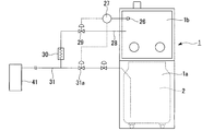
- FIG. 1 is a schematic configuration diagram showing an example of a glove box 1 of the present invention.
- the glove box 1 of this example is a rectangular parallelepiped box whose outer dimensions are approximately 2000 mm in height, 1000 mm in width, and 1000 mm in depth.
- the glove box 1 is vertically divided into two by a partition plate 1c, and is composed of an upper loading / unloading work space portion (hereinafter referred to as a work space portion) 1b and a lower storage portion 1a.
- the storage portion 1a and the work space portion 1b have a cubic shape with a side of approximately 1000 mm.
- the storage unit 1a stores the cryopreservation container 2, and the partition plate 1c is formed with a circular through hole at the center thereof, and the storage unit is connected to the storage space 1b through the through hole. It is comprised so that the opening part of the cryopreservation container 2 in 1a can be expected.
- the cryopreservation container 2 can be taken in and out of the storage part 1a by opening and closing the door 3 formed on one side surface of the storage part 1a.
- the opening part of the cryopreservation container 2 built in the storage part 1a has the opening part that faces the work space part 1b and communicates therewith, and the ampoule storage tool can be taken in and out from the opening part.
- An ampoule entry / exit box 32 is formed on the outer wall surface of the storage portion 1a.
- the ampoule entrance / exit box 32 is for temporarily storing an ampoule taken out from the cryopreservation container 2 or an ampoule to be accommodated in the cryopreservation container 2.
- the ampoule entry / exit box 32 is formed on the partition plate 1c. It communicates with the opening 1d (see FIG. 2).
- FIG. 2 shows an example of the ampoule entrance / exit box 32.
- the ampoule entry / exit box 32 is provided immediately below the partition plate 1c and at positions corresponding to the four corners of the partition plate 1c, and is positioned so as to avoid the circular container body 8 of the cryopreservation container 2.
- the ampoule entry / exit box 32 is a normal drawer with a lid 32a, and an opening 32b for dropping the ampoule 25 is formed in the lid 32a.
- the opening 32b communicates with the opening 1d formed in the partition plate 1c when the ampoule entrance / exit box 32 is pushed.
- the opening formed in the outer wall of the storage part 1a is hermetically closed by the front plate 32c of the ampoule entry / exit box 32.
- the opening 1d formed in the partition plate 1c is hermetically closed by the lid 32a.
- the work space portion 1b is formed by covering the periphery with a transparent plate made of glass, acrylic resin, or the like, and is configured so that the work in the work space portion 1b can be visually recognized from the outside.
- the work space portion The front and both sides of 1b are covered with an acrylic resin plate.
- surroundings of the work space part 1b can be made double, and heat insulation can be given, and the dew condensation and frost formation on the outer surface of an acrylic resin board can also be prevented.
- Round glove mounting openings 4 are formed at two locations on one surface on the front surface of the transparent plate covering the work space portion 1b, one side plate, and the opposite side plate.
- a rubber glove attachment frame 5 is attached to the opening 4...
- a rubber glove 6 is attached to the glove attachment frame 5.
- the openings 4 are installed at a position of 1300 to 1400 mm from the floor so that the operator can put on the gloves 6 and smoothly carry out the loading and unloading work while the operator is standing.
- FIG. 1 the state which attached the globe 6 only to the opening part 4 formed in the surface of one side plate is drawn.
- the work space portion 1b can be worked from three directions. Therefore, the ampoule storage tool 10 is disposed over the entire opening of the cryopreservation container 2. Also, using the globe 6 formed on any one of the three surfaces, it is possible to easily perform the loading / unloading operation.
- the exhaust wall 7 is formed in the ceiling wall of the work space 1b, and a backflow prevention mechanism or a filter (not shown) is attached to prevent the ingress of dust in the atmosphere.
- a dew point sensor 26 is attached in the work space 1b.
- the dew point sensor 26 measures the amount of moisture in the atmospheric gas in the work space 1b, and a signal from the dew point sensor 26 is sent to the dew point meter 27. In the dew point meter 27, the measured moisture amount is measured. Based on this, the dew point in the work space 1b is calculated.
- the dew point in the work space 1b is set in advance to, for example, ⁇ 50 ° C., and when the dew point calculated by the dew point meter 27 becomes equal to or higher than the set dew point, the work is performed from the dry gas supply pipe 28. It is comprised so that dry gas may be supplied in the space part 1b.
- One end of the dry gas supply pipe 28 opens into the work space 1b, and the other end is connected to a liquefied gas supply pipe 31 described later via a flow rate adjustment valve 29 and a vaporizer 30.
- the flow rate adjustment valve 29 controls the flow rate of the dry gas by a control signal from the dew point meter 27.
- the low-temperature liquefied gas divided from the liquefied gas supply pipe 31 is vaporized by the vaporizer 30 to become dry gas, and the flow rate is controlled by the flow rate adjusting valve 29 and introduced into the work space 1b.
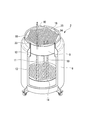
- the cryopreservation container 2 is generally composed of a container body 8, a cap 9, ampoule storage devices 10, and sheath tubes 11.
- the cryopreservation container 2 has a double structure formed of an inner tank 12 and an outer tank 13 made of stainless steel or the like, and is a vacuum double insulated container in which a gap between the inner tank 12 and the outer tank 13 is a vacuum. is there.
- the eye plate 14 is attached in the vicinity of the bottom of the inner tank 12 of the container main body 8 so that the vicinity of the eye plate 14 is filled with a low-temperature liquefied gas such as liquefied nitrogen.
- the opening diameter of the opening part of the inner tank 12 is slightly smaller than the inner diameter of the trunk
- the cryopreservation container 2 is provided with a liquefied gas supply pipe 31 for supplying or replenishing a low-temperature liquefied gas into the container body 8.
- a liquefied gas supply pipe 31 for supplying or replenishing a low-temperature liquefied gas into the container body 8.
- One end of the liquefied gas supply pipe 31 extends through the side wall of the storage section 1a of the glove box 1 and the side wall of the container body 8 to the vicinity of the bottom of the inner tank 12, and the other end is connected to the flow rate adjusting valve 31a.
- a liquid level sensor 42 for detecting the stored liquid level of the low-temperature liquefied gas and a temperature sensor 43 for detecting the temperature of the gas phase in the container body 8 are provided.
- the detection signals from these sensors 42 and 43 are sent to the liquefied gas supply source 41 to control the supply time and supply amount of the low-temperature liquefied gas supplied into the container body 8.
- the mouth of the inner tank 12 of the container body 8 is closed with a cap 9 so that it can be opened and closed.
- the cap 9 has a cylindrical shape whose outer diameter is substantially the same as the opening diameter of the mouth of the inner tank 12, and as shown in FIG. 15 and a lower plate 16 and a heat insulator 17 made of a heat insulating material such as a urethane foam resin between them and having a thickness of about 200 to 300 mm and having a high heat insulating performance.
- a large number of, for example, 300 to 500 insertion holes 18 are formed in the cap 9 so as to penetrate the cap 9 in the thickness direction (vertical direction).
- the inner diameter of the insertion hole 18 is about 15 to 25 mm.
- All of the insertion holes 18 are configured so that the sheath tubes 11 are inserted therein.
- the sheath tube 11 is a straight tube having an outer diameter of 15 to 25 mm, an inner diameter of 13 to 23 mm, and a length of about 500 to 700 mm.
- the bottom part reaches the eye plate 14, and the mouth part is The cap 9 is exposed and opened on the upper surface.
- the portion of the upper portion of the sheath tube 11 that is in contact with the cap 9 is made of a resin pipe, and the lower portion is made of stainless steel, aluminum alloy, or the like.
- a large number of small-diameter gas permeation holes 19 are formed on the peripheral wall of the sheath tube 11.
- a fixing claw (not shown) for fixing the sheath tube 11 to the cap 9 is integrally attached to the top portion of the sheath tube 11, and is attached to the upper edge portion (upper plate 15) of the insertion hole 18 of the cap 9. By engaging the fixing claw with the formed engaging recess (not shown), the sheath tube 11 is fixed to the cap 9 so that the sheath tube 11 cannot be pulled up simultaneously with the lifting of the ampoule container 10. It has become.
- Ampule housings 10 are inserted into the sheath tubes 11 so as to be movable in the vertical direction.
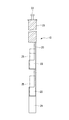
- the ampoule storage device 10 includes a support column 20 made of stainless steel, an aluminum alloy, etc., a round bar-like heat insulating portion 21 provided on the upper portion of the support column 20, and the heat insulating portion 21.
- the handle portion 22 is attached to the upper portion, and a plurality of, for example, eight, ampule storage portions 23 are arranged side by side in the vertical direction of the support column 20.
- the support column 20 has a strip-like shape whose horizontal cross-sectional shape is curved in an arc shape, and a guide pipe 24 is provided at the lower end thereof.
- the guide pipe 24 is for preventing the ampoule storage device 10 from being detached from the cap 9 even when the ampoule storage device 10 is pulled up to the lowermost ampoule storage portion 23.
- the guide pipe 24 is not necessarily required.
- the heat insulating portion 21 has an outer diameter that is substantially the same as the inner diameter of the sheath tube 11, and the vertical length thereof is substantially the same as the vertical thickness of the cap 9.
- the inside of the heat insulating portion 21 is made of a synthetic resin such as glass fiber reinforced epoxy resin, and the peripheral portion is formed of a foamed resin such as a urethane foam resin, so that the heat insulating performance is high.
- the support column 20 is not positioned on the central axis of the heat insulating portion, and the support column 20 is connected to the side portion of the heat insulating portion 21.
- the ampoule storage unit 23 is a bottomed cylindrical cup-shaped member that holds and stores one ampoule 25 enclosing a sample to be cryopreserved, and is provided integrally with the side of the support column 20. Yes. Regarding the vertical spacing of the ampoule storage portion 23, when the ampule 25 is stored in the ampule storage portion 23, a gap of about 5 to 10 mm is generated between the top portion of the ampule 25 and the bottom portion of the ampule storage portion 23 above it. The interval between them is determined.
- the ampoule storage part 23 has an outer diameter slightly smaller than the outer diameter of the heat insulating part 21, and the support column is arranged so that the central axis thereof substantially coincides with the central axis of the heat insulating part 21. 20 is attached.
- a ring-shaped packing 33 made of a cushioning material such as sponge or rubber is fixed to the upper end portion of the container body 8 of the cryopreservation container 2, and the cryopreservation container 2 is stored in the storage portion 1a.
- the packing 33 is pressed against the lower surface of the partition plate 1c when stored in the fixed position.
- the door of the storage section 1a is opened, the tray (not shown) stored in the storage section 1a is pulled out, and the cryopreservation container 2 is placed on this tray.
- the cryopreservation container 2 is pushed into the inside.
- the cryopreservation container 2 reaches a fixed position, the cryopreservation container 2 is fixed in a state where it is lifted slightly upward, whereby the packing 33 is brought into close contact with the lower surface of the partition plate 1c. become.
- a gas vent pipe 34 is provided through the peripheral portion of the cap 9 of the cryopreservation container 2, and a gas vent valve 35 is attached to the upper portion of the gas vent pipe 34.
- the inner tank 12 of the container body 8 is filled with the low-temperature gas in which a part of the low-temperature liquefied gas is vaporized, and this low-temperature gas passes through the gas permeation holes 19 of the sheath tube 11.
- the ampoule storage device 10 is reached, and the ampoule 25 held by the ampoule storage device 10 is cooled to a frozen state.
- the ampule 25 accommodated in the cryopreservation container 2 is generally a pre-frozen ampule, but it may be an ampule in another state.
- cryopreservation container 2 having such a structure, a large number of ampoules 25 can be accommodated in one cryopreservation container 2 as compared with the conventional one. Moreover, since the number of ampoules accommodated per ampule storage tool 10 is reduced, the number of times ampoules 25 are taken out of the cryopreservation container 2 during loading / unloading operations is greatly reduced, and the frequency of frost formation on the ampules is reduced. There are advantages to doing.
- the usage method of the glove box 1 of such a structure is demonstrated.
- the inner tank 12 of the container body 8 is filled with a low-temperature liquefied gas such as liquefied nitrogen up to the vicinity of the eye plate 14.
- the opening of the cryopreservation container 2 is closed with the cap 9, and the sheath tubes 11 are inserted into all the insertion holes 18 of the cap 9.
- a dry gas such as nitrogen gas is introduced into the work space 1b from the dry gas supply pipe 28 so that the pressure inside the work space 1b is set to a positive pressure about 0.1 to 10% higher than the external pressure. Is prevented from entering the glove box 1.
- the method of performing the dry gas through the dry gas supply pipe 28 as described above and the freezing through the degassing pipe 34 provided in the cap 9 of the cryopreservation container 2 are used.
- the dry gas in the work space 1b is exhausted from the exhaust port 7 as necessary. Since the exhaust port 7 is provided with a filter and a backflow prevention mechanism, it flows from the work space 1b to the work space 1b, but does not flow from the work space 1b to the work space 1b. Absent. Thereby, the inside of the work space 1b is always filled with the dry gas.
- the ampoule 25 enclosing the sample to be cryopreserved is put into the ampoule entry / exit box 32 and brought into the work space 1b.
- the predetermined ampoule storage tool 10 is pulled up from the cryopreservation container 2.
- the ampoule 25 in the ampoule loading / unloading box 32 is taken out and stored in the ampoule storage part 23 of the predetermined ampoule storage tool 10, and then the ampoule storage tool 10 is pushed into the cryopreservation container 2.
- the work for taking out the ampule 25 from the cryopreservation container 2 is the reverse of the work for housing the ampule 25 described above.
- the handle 22 exposed on the surface of the cap 9 of each ampoule storage device 10 or the sheath tube 11 into which the ampoule storage device 10 is inserted has a first identification code (for example, 1, 2). 3 ... n), the number of ampoules 25 accommodated in one ampoule storage device 10 is set to 8, and second identification codes A, B, C.
- a first identification code for example, 1, 2). 3 ... n
- second identification codes A, B, C As a result, one ampule 25 can be identified and managed by the identification management number “2-B”, for example.
- the ampoule storage device 10 in which the target ampoule 25 is stored can be known from the outside of the cryopreservation container 2.
- the ampoule storage tool 10 with the first identification code “2” is visually recognized from the outside of the cryopreservation container 2. Therefore, it is pulled up from the sheath tube 11, and the second ampoule 25 (second identification code “B”) is taken out from above. At this time, the ampule housing 10 is lifted up to the position where the second ampule 25 can be taken out from the top, and the ampule 25 located from the third to the bottom does not touch the outside air. The same applies to the case where another ampule 25 is newly accommodated in the vacant ampule accommodating portion 23 of the ampule container 10.
- the ampoule 25 can be recovered from the sheath tube 11, which is valuable.
- the sample is not wasted. Further, since the cap 9 does not need to be removed from the cryopreservation container 2 when the ampoule storage device 10 is pulled up and inserted, the consumption of the low-temperature liquefied gas can be reduced.
- the shape of the ampoule storage part 23 of the ampoule storage tool 10 is not limited to the above-described shape, and for example, the two locking claw pieces have a structure in which two locking claw pieces extend from both sides of the support pillar 20. 25 may be held and held.
- FIGS. One embodiment of a glove box equipped with an automatic handling robot
- the ampoule loading / unloading operation can be performed not only by manual operation using the glove 6 but also by semi-automatic operation using an automatic handling robot.
- 8 to 10 show an example of a clove box having an automatic handling robot.
- the automatic handling robot here is provided in the upper space of the work space 1b.
- a pair of parallel X-axis rails 51, 51 are attached to the upper portion of the work space 1b.
- the X-axis rail 51 has, for example, a smooth round bar shape, and is disposed on one end edge portion of the ceiling wall and the other end edge portion facing it.
- a pair of X-axis mounts 52 and 52 that reciprocate along the X-axis rail 51 are mounted on the X-axis rails 51 and 51, respectively.
- the X-axis mount 52 is a hollow cylindrical member, and is configured such that the X-axis rail 51 is inserted into and slides through a hollow portion inside thereof, and reciprocates in the X-axis direction.
- the pair of X-axis mounts 52 and 52 are spanned by two Y-axis rails 53 and 53 that are parallel to each other, for example, so as to connect them.
- the pair of Y-axis rails 53, 53 is attached with a single Y-axis rack 54 that reciprocates between the pair of Y-axis rails 53, 53.
- the Y-axis mount 54 includes a pair of sliding bodies 55 and 55 and a connecting body 56 that connects the pair of sliding bodies 55 and 55.
- the sliding body 55 is formed of a hollow cylindrical body, and is configured such that the Y-axis rail 53 is inserted into and slides into a hollow portion inside thereof, and reciprocates in the Y-axis direction. Will also reciprocate in the Y-axis direction.
- one Z-axis rail 57 is suspended from the Y-axis mount 54 and attached thereto.
- the Z-axis rail 57 has a tip extending to the vicinity of the partition plate 1c.
- a gripping head 58 is attached to the Z-axis rail 57 so as to be movable up and down.
- the pair of gripping pieces 59, 59 are adapted to approach or separate from each other, whereby the handle portion 22 can be gripped or released.
- the shape of the handle portion 22 is a prismatic shape, whereby when the handle portion 22 is gripped by the gripping pieces 59, 59, the direction of the ampule housing portion 23 of the ampule housing tool 10 is determined, The direction can be the operator side. Also, barcode reading, ampoule removal, and storage operations are facilitated.
- the gripping head 58 can freely move in the three axial directions in the X-axis direction, the Y-axis direction, and the Z-axis direction in the work space, and is thereby accommodated in the cryopreservation container 2.
- Arbitrary ampoule storage tool 10 can be pulled up to an arbitrary position.
- the operation of the gripping head 58 is controlled by the control device 60 installed outside the glove box 1.
- the operation of taking out and attaching the ampule by the robot is performed as follows. First, since the position of the cryopreservation container 2 in the storage unit 1a may slightly shift due to the insertion / extraction of the cryopreservation container 2, it is necessary to determine the reference point (origin) of the gripping head 58 each time.
- This reference point is set by lifting the specific ampoule storage device 10 from the cryopreservation container 2 to a predetermined position, moving the grip pieces 59, 59 of the grip head 58 to this position, and using the grip pieces 59, 59 to move the handle portion. 22 is gripped.
- the identification management number of the ampoule 25 or the ampoule housing part 23 exposed is input to the control device 60 and teaching is performed for 2 to 3 ampoule housings 10.
- the identification management number is input to the control device 60 using an input device 61 such as a graphic panel.
- arbitrary reference points are provided on the upper surface of the cap 9 in advance, and the position of each ampoule storage tool 10 and the position of the reference point are stored in the control device 60 in advance.
- the robot visible by the laser beam
- the robot is returned to the reference point by fine adjustment driving, and is re-stored, but is not limited thereto.
- the height of the cryopreservation container 2 by a level adjuster attached to the foot of the container 2.
- the identification management number of the ampule to be taken out is input to the input device 61.
- the gripping head 58 moves to the target position, the gripping pieces 59, 59 grip the handle portion 22 of the target ampoule storage tool 10, and the ampoule storage tool 10 is pulled up until the target ampoule 25 is exposed to the outside. Stop.
- the operator inserts his / her hand into the glove 6... Of the work space portion 1 b and removes it manually from the ampoule storage device 10, puts it in the ampoule entry / exit box 32, and takes it out of the glove box 1.
- the gripping head 58 pushes the ampoule storage tool 10 into the cryopreservation container 2 and opens the gripping pieces 59, 59, and then enters the standby position.
- the target ampoule storage device 10 is lifted from the cryopreservation container 2 in the same manner as the removal, and the target empty ampoule storage unit 23 is exposed. In this state, the operator manually accommodates the ampule in the empty ampule accommodating portion 23.
- the gripping head 58 pushes the ampoule storage device 10 into the cryopreservation container, opens the gripping pieces 59, 59, and then returns to the standby position. .
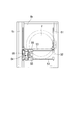
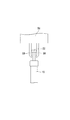
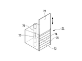
- a pass box 71 is provided in the vicinity of the partition plate 1c in the loading / unloading work space 1b.
- the pass box 71 is a substantially rectangular parallelepiped box made of a transparent material such as glass, acrylic resin, and carbonate resin.
- One side surface of the pass box 71 is exposed so as to face the outside through an opening formed by cutting out a part of the wall forming the work space portion 1 b, and this side surface serves as an operation port 72.
- the operation port 72 needs to be airtight at all times. Normally, as shown in FIG. 12, the operation port 72 is closed by an outer door 73 made of a transparent plate, and when necessary, the outer door 73 moves upward or sideways. The inner door 74 appears.
- the inner door 74 is configured by arranging a plurality of flexible belts 75, 75,... Made of a flexible material such as rubber and soft foamed plastic in the vertical direction with no gap therebetween. , 75 so that the operator can insert his hand and work in the pass box 71.
- the outer door 73 can also be abbreviate
- the longitudinal direction of the flexible belts 75, 75... Is the horizontal direction, but may be other than the horizontal direction.
- the longitudinal direction of the flexible belts 75, 75... May be the vertical direction. In this case, the flexible belts 75, 75.
- the pass box 71 is provided with an upper accommodating pipe 76 that penetrates from the upper surface to the lower surface.
- the upper housing pipe 76 is for inserting the ampoule housing 10 pulled out from the cryopreservation container 2 by the robot.
- an extraction window 77 is formed in the upper accommodation pipe 76. This take-out window 77 is for the operator to grasp and take out the target ampoule 25 from the ampoule holder 10 when the ampoule holder 10 is inserted into the upper receiving pipe 76, and is larger than the size of the ampoule 25. A slightly larger opening.
- the pass box 71 is provided with a discharge port 78 that fills the inside thereof with at least a dry gas during operation and discharges a dry gas to make a positive pressure. Is connected to the aforementioned dry gas supply pipe 28 (see FIG. 3).
- one fixed bar code reader 79, 79 is provided on each of both sides thereof.
- the bar code reader 79 reads the bar code on the bar code label attached to the ampoule 25 and performs identification management of the ampoule 25.
- the bar code information from the bar code readers 79 and 79 is the control device 60. To be input.
- the barcode reader 79 is not limited to two, and may be one.
- the cryopreservation container 2 is provided with a lower housing pipe 80.
- the lower housing pipe 80 is for housing the lower part of the ampoule housing 10 when the ampoule housing 10 pulled out by the robot is inserted into the upper housing pipe 76. Depending on the insertion depth, the lower part may not be accommodated.
- the lower housing pipe 80 is provided through the cap 9 of the cryopreservation container 2 so as to reach the inner tank 12.
- the planar position of the lower housing pipe 80 is directly below the upper housing pipe 76, whereby one ampoule housing 10 is inserted and housed through the upper housing pipe 76 and the lower housing pipe 80. become.
- a bar-shaped leg portion 81 extending downward is attached to the Z-axis rail 57.
- the leg portion 81 can move up and down along the Z-axis rail 57.
- a through hole for the leg 81 is formed in the gripping head 58, and the gripping head 58 can move up and down along the Z-axis rail 57 and the leg 81.
- a clamp 82 that holds the lower end portion of the ampoule storage device 10 is provided at the lower end portion of the leg portion 81.
- the leg 81 is lowered to the lower end of the Z-axis rail 57 and the clamp 82 is opened, whereby the gripping piece of the gripping head 58 is opened. 59 and 59 are not disturbed.
- the leg portion 81 is not limited to the above example, and may be directly attached to the gripping head 58. In this case, the shape of the leg portion 81 is made to be an extendable shape.
- the leg portion 81 contracts on the cap 9 and the clamp 82 opens, and the gripping piece 59 of the gripping head 58, 59 operation is not disturbed.
- the clamp 82 may be directly attached to the Z-axis rail 57. In this case, the clamp 82 can move up and down along the Z-axis rail 57. As a result, when the gripping head 58 approaches the cap 9 in order to pull out the ampoule storage device 10, the clamp 82 is lowered to the lower end of the Z-axis rail 57 and opens, and the gripping pieces 59, 59 of the gripping head 58 are opened. Is not disturbed.
- control device 60 incorporates a program for executing the following operations. That is, when an ampule identification management number is input to the input device 61, the gripping head 58 pulls out the target ampule housing 10 and holds the lower portion thereof with the clamp 82. The ampule housing 10 in this state is held in the upper housing pipe. The ampule holder 10 is further inserted into the upper receiving pipe 76 or the upper receiving pipe 76 and the lower receiving pipe 80, and is stopped when the target ampule 25 comes to the position of the extraction window 77. A series of operations are performed.
- a bar code label on which information such as an identification management number is recorded is affixed to the body of all ampoules 25 (not shown).
- the gloves 6, 6,... And the ampoule entry / exit boxes 32, 32 are not necessary.
- the control device 60 executes the program, the robot's gripping head 58 pulls the target ampule storage device 10 out of the cryopreservation container, and the ampule is stored in the clamp 82.
- the lower part of the tool 10 is held, and in this state, the ampoule storage tool 10 is moved to a position immediately above the upper storage pipe 76 of the pass box 71.
- the ampoule storage device 10 is inserted into the upper housing pipe 76, and when the target ampoule descends to the position of the extraction window 77 of the upper housing pipe 76, the ampoule is stored. The insertion of the storage tool 10 is stopped. At this time, the ampoule 25 accommodated in the ampoule container 10 faces the extraction window 77. At this time, the two bar code readers 79, 79 read the bar code of the ampoule exposed in the take-out window 77 and send the identification management number to the control device 60.
- the control device 60 compares the identification management number from the bar code readers 79 and 79 with the identification management number from the input device 61, and if they match, confirms that the target ampoule is the target, and displays an indicator lamp and a display buzzer. And so on. After confirming this display, the operator opens the outer door 73 of the pass box 71, inserts a hand from the inner door 74 through the operation port 72, and takes out the ampoule.
- the gripping head 58 pulls out the ampoule storage tool 10 from the upper storage pipe 76 and inserts it into the original position of the cryopreservation container 2, so Ends.
- the shape of the lower part of the heat insulating part 21 and the lower part of the guide pipe 24 of the ampoule storage device 10 is changed. By making it taper so as to be thinner than the body (not shown), it can be inserted more smoothly.
- the target ampoule storage device 10 When the ampoule is stored in the ampoule storage device 10, the target ampoule storage device 10 is lifted from the cryopreservation container 2 and inserted into the upper storage pipe 76 in the same manner as the removal, and the target empty ampoule is stored. The accommodating part 23 is exposed to the extraction window 77. In this state, the operator manually accommodates the ampule in the empty ampule accommodating portion 23 through the operation port 72 of the pass box 71.
- the barcode attached to the ampoule is read by the barcode readers 79 and 79, the identification management number is sent to the control device 60, and compared with the identification management number inputted to the input device 61, and the target ampoule is the target. It is confirmed whether it was accommodated in the ampule accommodating part 23.
- the operator presses the “take-out completion button” of the input device 61.
- the gripping head 58 of the robot pulls out the ampoule storage tool 10 from the upper storage pipe 76, inserts it into the original position of the cryopreservation container 2, completes the warehousing operation, and returns to the standby position.
- the atmosphere in the pass box 71 can be in a dry state, and frost does not adhere to the ampoule exposed to the extraction window 77.
- the bar code attached to the ampoule is surely read by the bar code readers 79 and 79 without error.
- a considerable part of the loading / unloading operation of the ampoule, especially the operation for identifying the ampoule is automatically performed, and the burden on the operator is greatly reduced.
- the target ampule is stored in the ampule storage portion 23 at the top of the ampule storage device 10
- most of the ampoule storage device 10 is located in the lower storage pipe 80 of the cryopreservation container 2.
- the ampoule present in is kept in a cooled state. For this reason, the frequency with which unnecessary heat is applied to the ampoule is reduced.
- FIG. 14 shows a main part of a modification of the embodiment.
- the pass box 71 does not have the upper accommodating pipe 76, and a vertical groove 83 is provided on the back surface of the pass box 71 instead.
- the longitudinal groove 83 has a semicircular cross-sectional shape, and is formed on the back surface of the pass box 71 along the vertical direction. 77 is formed.
- the take-out window 77 is for taking out the ampule in the same manner as in the previous example.
- the ampoule storage tool 10 pulled out from the cryopreservation container 2 is lowered along the longitudinal groove 83, and the target ampoule is taken out or stored from the extraction window 77.
- the pass box 71 is disposed at the central portion of one side surface of the entry / exit space 1b from the viewpoint of operability.
- the present invention is not limited to this and may be disposed at the corner of the pass box 71. .
- the lower housing pipe 80 cannot be provided inside the cryopreservation container 2, or there are cases where the lower housing pipe 80 may not be provided. For this reason, the lower part of the ampule housing 10 inserted into the upper housing pipe 76 of the pass box 71 is exposed to room temperature.
- various biological samples can be stably stored for a long time in each research institution or medical institution in the bio field, the medical field, the pharmaceutical field, or the livestock field.
Landscapes
- Engineering & Computer Science (AREA)
- Life Sciences & Earth Sciences (AREA)
- Zoology (AREA)
- Dentistry (AREA)
- General Health & Medical Sciences (AREA)
- Wood Science & Technology (AREA)
- Health & Medical Sciences (AREA)
- Environmental Sciences (AREA)
- Chemical & Material Sciences (AREA)
- Combustion & Propulsion (AREA)
- Physics & Mathematics (AREA)
- Mechanical Engineering (AREA)
- Thermal Sciences (AREA)
- General Engineering & Computer Science (AREA)
- Medical Preparation Storing Or Oral Administration Devices (AREA)
Abstract
Description
本願は、2008年01月18日に日本に出願された特願2008-009393号、及び2008年10月17日に日本に出願された特願2008-268768号に基づき優先権を主張し、その内容をここに援用する。
また、アンプルやアンプル収納具に付着した霜が入出庫の度に凍結保存容器内に霜や氷粒として蓄積されるため、これらを取り除く場合は、定期的に凍結保存容器内のアンプルなど保存試料を移設した後、該容器内の液体窒素を除去し、容器内を乾燥させる、所謂メンテナンスを行う必要があった。
本発明の第1の態様は、低温液化ガスを貯える容器本体と、この容器本体の口部を閉じるとともに複数の挿入孔が上下方向(vertical direction)に貫通して形成されたキャップと、このキャップの挿入孔に挿通可能に収容されたアンプル収納具を備え、前記アンプル収納具が、支持柱とこの支持柱の上下方向に並んで取り付けられた複数のアンプル収納部とから構成されている凍結保存容器である。
言い換えると、本発明の第1の態様は、低温液化ガスを貯える容器本体と、この容器本体の口部を閉じるとともに複数の挿入孔が上下方向に貫通して形成されたキャップと、このキャップの挿入孔に挿入された鞘管と、この鞘管に挿通可能に収容されたアンプル収納具を備え、前記鞘管には、複数のガス透過孔が形成されており、前記アンプル収納具が、支持柱とこの支持柱の上下方向に並んで取り付けられた複数のアンプル収納部とから構成されていることが好ましい。
また、本発明の第2の態様においては、前記アンプルにはバーコードが付され、このバーコードの識別管理情報に基づいて、前記自動ハンドリングロボットが取り出したアンプル収納具のアンプルを識別することが好ましい。
(グローブボックス)
図1は、本発明のグローブボックス1の一例を示す概略構成図である。この例のグローブボックス1は、その外形寸法がおよそ、高さ2000mm、幅1000mm、奥行1000mmの直方体状のボックスである。
このアンプル出入箱32は、凍結保存容器2から取り出したアンプルまたは凍結保存容器2に収容するアンプルを一時的に収容するためのもので、このアンプル出入箱32は、前記仕切り板1cに形成された開口1dと連通されている(図2参照)。
このアンプル出入箱32は、通常の蓋32a付きの引き出しであって、この蓋32aには、アンプル25を落とし込むための開口32bが形成されている。この開口32bは、アンプル出入箱32を押し込んだ際に、仕切り板1cに形成されている開口1dと連通するようになっている。
開口部4…は、操作者が立位の作業状態で、グローブ6…を装着して入出庫作業が円滑にできるように、床から1300~1400mmの位置に設置されている。なお、図1では、一方の側板の面に形成された開口部4にのみグローブ6を取り付けた状態を描いている。
乾燥ガス供給管28の一端は、作業空間部1b内に開口しており、その他端は、流量調整弁29、気化器30を介して後述する液化ガス供給管31に接続されている。
液化ガス供給管31から分流した低温液化ガスは、気化器30で気化して乾燥ガスとなり、流量調整弁29にて流量制御されて作業空間部1bに導入される。
凍結保存容器2は、図4に示すように、容器本体8とキャップ9とアンプル収納具10…と鞘管11…とから概略構成されている。凍結保存容器2は、ステンレス鋼などからなる内槽12と外槽13から形成される二重構造であり、内槽12と外槽13との間の空隙が真空である真空二重断熱容器である。
鞘管11…の上部の前記キャップ9に接する部分は、樹脂パイプから構成され、これより下側の部分はステンレス鋼、アルミニウム合金などから構成されている。
鞘管11の頂部には、この鞘管11をキャップ9に固定するための固定爪(図示略)が一体に取り付けられており、キャップ9の挿入孔18の上縁部(上板15)に形成された係合凹部(図示略)に前記固定爪を係合することで、鞘管11がキャップ9に固定され、アンプル収容具10の引き上げに伴って鞘管11が同時に引き上げられないようになっている。
前記鞘管11…内には、アンプル収納具10…が上下方向に移動可能に挿通されている。このアンプル収納具10は、図7に示すように、ステンレス鋼、アルミニウム合金などからなる支持柱20と、この支持柱20の上部に設けられた丸棒状の断熱部21と、この断熱部21の上部に取り付けられた取っ手部22と、支持柱20の上下方向に間隔を配して複数個、例えば8個並んで設けられたアンプル収納部23…とから構成されている。
前記断熱部21は、その外径が前記鞘管11の内径とほぼ同径とされており、その上下方向の長さは前記キャップ9の上下方向の厚さとほぼ同じとなっている。
図7に示すように、前記支持柱20は前記断熱部の中心軸上には位置しておらず、支持柱20が断熱部21の側部に連設された状態となっている。
これにより、多数のアンプル25…を凍結状態で保存し、凍結保存することができる。
なお、凍結保存容器2に収容するアンプル25は、予備凍結した状態のアンプルが一般的であるが、その他の状態のアンプルであってもよい。
次に、このような構造のグローブボックス1の使用方法について説明する。
はじめに、容器本体8の内槽12内に液化窒素などの低温液化ガスを目皿14付近まで満たしておく。
次に、凍結保存容器2の開口部をキャップ9で閉じ、キャップ9のすべての挿入孔18…に鞘管11…を挿入する。
これにより、作業空間部1b内は乾燥ガスで常時充満された状態となる。
また、凍結保存容器2の外部から目的とするアンプル25が納められているアンプル収納具10を知ることができる。
また、アンプル収納具10の空いたアンプル収容部23に新たに別のアンプル25を収納する場合でも同様である。
また、アンプル収納具10の引き上げ、挿入に際して、キャップ9を凍結保存容器2から取り外す必要がないので、低温液化ガスの消費量を低減できる。
さらに、目皿14が取り付けられていない凍結保存容器2であってもなんら支障がないことは言うまでもない。
(自動ハンドリングロボットが装備されたグローブボックスの一実施形態)
前記アンプルの入出庫作業は、グローブ6を使用したマニュアル操作以外に自動ハンドリングロボットを用いた半自動操作によっても行うことができる。
図8ないし図10は、自動ハンドリングロボットを備えたクローブボックスの一例を示すものである。ここでの自動ハンドリングロボット(以下、ロボットと言う。)は、作業空間部1bの上部空間に設けられている。
X軸レール51、51には、それぞれこのX軸レール51を往復移動する一対のX軸架台52、52が装着されている。このX軸架台52は、中空の円筒状の部材であって、その内部の中空部に前記X軸レール51が挿通されて摺動し、X軸方向に往復移動するように構成されている。
摺動体55は、中空円筒体からなり、その内部の中空部に前記Y軸レール53が挿通されて摺動し、Y軸方向に往復移動するように構成されており、これによりY軸架台54もY軸方向に往復移動することになる。
この把持ヘッド58の下面には、図10に示すように、前記アンプル収納具10の取っ手部22を把持する一対の把持片59、59が設けられている。
この一対の把持片59、59は、互いに接近もしくは離間するようになっており、これにより前記取っ手部22を把持もしくは開放できるようになっている。
この例では、前記取っ手部22の形状を角柱状とすることが好ましく、これにより把持片59、59で取っ手部22を把持した際に、アンプル収納具10のアンプル収容部23の向きが定まり、その向きを操作者側とすることができる。また、バーコードの読み取り、アンプルの取り出し、収容操作が容易となる。
このような把持ヘッド58の動作は、グローブボックス1外に設置されている制御装置60によって制御されるようになっている。
初めに、収納部1a内での凍結保存容器2の位置が、凍結保存容器2の出し入れによって僅かにずれることがあるので、その都度把持ヘッド58の基準点(原点)を定める必要がある。
また、XY軸方向については、予めキャップ9の上面に任意の基準点(2点)を設け、各アンプル収納具10の位置と基準点の位置は予めそれらの位置関係を制御装置60に記憶させておき、凍結保存容器2がずれた場合は、微調整の駆動によりロボット(レーザ光により視認可能)を基準点に戻し、再記憶させる設定方法もあるが、これらに限定されるものではない。
なお、Z軸については、取っ手部22の首下部を長めに取ることにより多少のずれに対しては対応可能であるが、凍結保存容器2の高さを容器2の足元に取り付けたレベルアジャスターにより調整し、把持片59、59の開閉位置と取っ手部22の位置を合わせることができる。
ついで、入力装置61の「取出投入完了ボタン」を押すと、把持ヘッド58は、そのアンプル収納具10を前記凍結保存容器2内に押し込み、把持片59、59を開放してから、待機位置に戻る。
この状態で、操作者が人手によりアンプルを空のアンプル収容部23に収容する。
ついで、入力装置61の「取出投入完了ボタン」を押すと、把持ヘッド58は、そのアンプル収納具10を前記凍結保存容器内に押し込み、把持片59、59を開放してから、待機位置に戻る。
凍結保存容器2には、300~500本程度のアンプル収納具10が挿入されているので、目視確認作業に手間取り、誤認する可能性があるが、このロボットを用いることでそのような不都合を解消できる。
図11ないし図13は、ロボットが装備されたグローブボックスの他の実施形態を示すものである。
この実施形態では、入出庫作業空間部1b内の仕切り板1c付近にパスボックス71が設けられている。このパスボックス71は、ガラス、アクリル樹脂、カーボネイト樹脂などの透明材料からなる略直方体状の内部が空洞の箱体である。
操作口72は、常時気密になっている必要があり、通常は図12に示すように、透明の板材からなる外扉73により閉じられ、必要時にはこの外扉73が上方または側方に移動して内扉74が表れるように構成されている。
この上部収容パイプ76には、図12に示すように、取出窓77が形成されている。この取出窓77は、アンプル収納具10を上部収容パイプ76に挿入したときに、アンプル収納具10から目的のアンプル25を操作者が手でつかんで取り出すためのもので、アンプル25の大きさよりも少し大きめの開口部である。
パスボックス71内には、その両側方にそれぞれ1基ずつの固定式のバーコードリーダー79、79が設けられている。このバーコードリーダー79は、アンプル25に付されたバーコードラベルのバーコードを読み取り、アンプル25の識別管理を行うためのもので、バーコードリーダー79、79からのバーコード情報は前記制御装置60に入力されるようになっている。
なお、バーコードリーダー79は、2基に限らず、1基であってもよい。
下部収容パイプ80は、凍結保存容器2のキャップ9を貫通して設けられ、内槽12内にまで届くようになっている。
脚部81は、上記の例に限らず、把持ヘッド58に直接取り付けてもよい。この場合、脚部81の形状を伸縮可能な形状にする。これにより、把持ヘッド58がアンプル収納具10を引き抜くためにキャップ9上に接近した場合には、脚部81がキャップ9上で縮むとともにクランプ82が開くこととなり、把持ヘッド58の把持片59、59の動作が妨害されない。
また、クランプ82は、Z軸レール57に直接取り付けてもよい。この場合、クランプ82はZ軸レール57に沿って上下動可能とする。これにより、把持ヘッド58がアンプル収納具10を引き抜くためにキャップ9上に接近した場合には、クランプ82がZ軸レール57の下端まで下がるとともに開くこととなり、把持ヘッド58の把持片59、59の動作が妨害されない。
すなわち、前記入力装置61にアンプルの識別管理番号を入力すると、把持ヘッド58が目的のアンプル収納具10を引き抜き、その下部をクランプ82で保持し、この状態のアンプル収納具10を前記上部収容パイプ76の直上にまで移動させ、さらにアンプル収納具10を上部収容パイプ76あるいは上部収容パイプ76と下部収容パイプ80とに挿入し、目的のアンプル25が前記取出窓77の位置に来た時に停止するようにする一連の動作を実行するものである。
前記入力装置61に取り出すべきアンプルの識別管理番号を入力すると、制御装置60が前記プログラムを実行し、ロボットの把持ヘッド58が目的のアンプル収納具10を凍結保存容器から引き抜き、クランプ82でアンプル収納具10の下部を保持し、この状態でアンプル収納具10をパスボックス71の上部収容パイプ76の直上の位置まで移動させる。
この時、2個のバーコードリーダー79、79が取出窓77に露出しているアンプルのバーコードを読み取り、その識別管理番号を制御装置60に送る。
操作者は、この表示を確認した後、パスボックス71の外扉73を開き、内扉74から操作口72を経て手を内部に差し込み、アンプルを取り出す。
なお、アンプル収納具10を凍結保存容器2の元の位置に挿入、あるいは前記上部収容パイプ76に挿入する際、アンプル収納具10の断熱部21の下部とガイドパイプ24の下部の形状をそれぞれの胴部より細くなるようにテーパ状とすること(図示略)によって、よりスムースに挿入することができる。
この状態で、操作者が人手によりパスボックス71の操作口72を介してアンプルを空のアンプル収容部23に収容する。
また、アンプルの入出庫作業のかなりの部分、特にアンプルの特定のための作業が自動的に行われ、操作者の負担が大幅に軽減される。
図14は、前記実施形態の変形例の要部を示すものである。
この変形例では、パスボックス71には上部収容パイプ76がなく、これにかわってパスボックス71の背面に縦溝部83が設けられている。この縦溝部83は、断面形状が半円状のもので、パスボックス71の背面に上下方向に沿う形で形成されているものであって、その中間部には、これを切り欠いて取出窓77が形成されている。この取出窓77は、先の例のものと同様にアンプルを取り出すためのものである。
Claims (13)
- 低温液化ガスを貯える容器本体と、この容器本体の口部を閉じるとともに複数の挿入孔が上下方向に貫通して形成されたキャップと、このキャップの挿入孔に挿通可能に収容されたアンプル収納具を備え、
前記アンプル収納具が、支持柱とこの支持柱の上下方向に並んで取り付けられた複数のアンプル収納部とから構成されている凍結保存容器。 - 前記キャップの挿入孔に挿入された鞘管をさらに備え、
前記アンプル収納具が前記鞘管に挿通可能に収容されており、
前記鞘管には、複数のガス透過孔が形成されている請求項1に記載の凍結保存容器。 - 請求項1に記載の凍結保存容器を収納した収納部と、
前記収納部の上部に連通して設けられた入出庫作業空間部とから構成され、
前記入出庫作業空間部が外部から透視可能となっているとともに、前記入出庫作業空間部が乾燥ガスで充満され陽圧とされており、
前記入出庫作業空間部の内部では、前記収納部に収容された凍結保存容器のアンプル収納具の入出庫作業が行われるグローブボックス。 - 前記入出庫作業空間部の壁面に逆流防止機構またはフィルタが取り付けられたガス排出口が設けられ、
前記収納部の壁面にアンプル出入箱が設けられている請求項3に記載のグローブボックス。 - 前記入出庫作業空間部内の露点を計測する露点計が設けられ、
この露点計の指示値が所定値以上となった場合に、該入出庫空間部内に、該空間部の露点を下げる乾燥ガスを供給する乾燥ガス供給部が設けられている請求項3に記載のグローブボックス。 - 前記入出庫作業空間部の天井部分に、特定のアンプル収納具を前記凍結保存容器から引き上げ、ついで押し込む自動ハンドリングロボットが設けられている請求項3に記載のグローブボックス。
- 前記自動ハンドリングロボットは、特定のアンプル収納具の位置およびこのアンプル収納具に収納されているアンプルの位置の指示に基づき、三軸制御により動作するものである請求項6に記載のグローブボックス。
- 前記自動ハンドリングロボットは、把持ヘッドを備え、この把持ヘッドが三軸方向に走行して特定のアンプル収納具の位置に移動し、このアンプル収納具を特定のアンプルが前記凍結保存容器から露出するまで引き上げ、ついで押し込むものである請求項7に記載のグローブボックス。
- 前記入出庫作業空間部にパスボックスが設けられ、
このパスボックスは外部に開口する気密な操作口を有し、かつ前記自動ハンドリングロボットによって前記凍結保存容器から引き上げられたアンプル収納具が挿入される上部収容パイプを有し、
この上部収容パイプには、挿入されたアンプル収納具からアンプルを取り出すための取出窓が形成されている請求項6に記載のグローブボックス。 - 前記入出庫作業空間部にパスボックスが設けられ、
このパスボックスは外部に開口する気密な操作口を有し、かつその背面には前記自動ハンドリングロボットによって前記凍結保存容器から引き上げられたアンプル収納具が添わされる縦溝部が形成され、
この縦溝部には、挿入されたアンプル収納具からアンプルを取り出すための取出窓が形成されている請求項6に記載のグローブボックス。 - 前記パスボックスは、透明材料によって作られ、その内部が乾燥ガスで充満されている請求項9または10に記載のグローブボックス。
- 前記アンプルにはバーコードが付され、このバーコードの識別管理情報に基づいて、前記自動ハンドリングロボットが取り出したアンプル収納具のアンプルを識別する請求項9または10に記載のグローブボックス。
- 前記凍結保存容器へ液化ガスを供給するための管路が設けられており、
この管路は前記収納部および凍結保存容器を貫通して、その一端が凍結保存容器の底部にまで延び、他端が液化ガス供給手段に接続されている請求項3に記載のグローブボックス。
Priority Applications (3)
| Application Number | Priority Date | Filing Date | Title |
|---|---|---|---|
| US12/812,354 US8770907B2 (en) | 2008-01-18 | 2008-11-11 | Cryopreservation device |
| CN200880108511.8A CN101808608B (zh) | 2008-01-18 | 2008-11-11 | 冷冻保存装置 |
| KR1020107006468A KR101247713B1 (ko) | 2008-01-18 | 2008-11-11 | 동결보존장치 |
Applications Claiming Priority (4)
| Application Number | Priority Date | Filing Date | Title |
|---|---|---|---|
| JP2008-009393 | 2008-01-18 | ||
| JP2008009393 | 2008-01-18 | ||
| JP2008-268768 | 2008-10-17 | ||
| JP2008268768A JP4648444B2 (ja) | 2008-01-18 | 2008-10-17 | グローブボックス |
Publications (1)
| Publication Number | Publication Date |
|---|---|
| WO2009090793A1 true WO2009090793A1 (ja) | 2009-07-23 |
Family
ID=40885196
Family Applications (1)
| Application Number | Title | Priority Date | Filing Date |
|---|---|---|---|
| PCT/JP2008/070495 Ceased WO2009090793A1 (ja) | 2008-01-18 | 2008-11-11 | 凍結保存装置 |
Country Status (1)
| Country | Link |
|---|---|
| WO (1) | WO2009090793A1 (ja) |
Cited By (1)
| Publication number | Priority date | Publication date | Assignee | Title |
|---|---|---|---|---|
| EP3403036A4 (en) * | 2016-01-11 | 2019-08-28 | Michalk-Allaire, Julien | INSTANT FREEZER AND METHOD OF USE THEREOF |
Citations (7)
| Publication number | Priority date | Publication date | Assignee | Title |
|---|---|---|---|---|
| JPH0549294U (ja) * | 1991-12-05 | 1993-06-29 | 信越化学工業株式会社 | グローブボックス |
| JPH06167431A (ja) * | 1992-11-27 | 1994-06-14 | Hitachi Ltd | 凍結保存装置 |
| JP2002214227A (ja) * | 2001-01-22 | 2002-07-31 | Dainakomu:Kk | 生体高分子の保存方法 |
| JP2005143873A (ja) * | 2003-11-17 | 2005-06-09 | Taiyo Nippon Sanso Corp | 凍結保存容器 |
| JP2007271279A (ja) * | 2006-03-30 | 2007-10-18 | Japan Agengy For Marine-Earth Science & Technology | 凍結保存器 |
| US20070267419A1 (en) * | 2004-10-01 | 2007-11-22 | Fraunhofer-Gesellschaft Zur Forderung Der Angewandten Forschung E. V. | Cryo-Device and Associated Operational Method |
| JP2008285181A (ja) * | 2007-05-16 | 2008-11-27 | Taiyo Nippon Sanso Corp | 凍結保存容器 |
-
2008
- 2008-11-11 WO PCT/JP2008/070495 patent/WO2009090793A1/ja not_active Ceased
Patent Citations (7)
| Publication number | Priority date | Publication date | Assignee | Title |
|---|---|---|---|---|
| JPH0549294U (ja) * | 1991-12-05 | 1993-06-29 | 信越化学工業株式会社 | グローブボックス |
| JPH06167431A (ja) * | 1992-11-27 | 1994-06-14 | Hitachi Ltd | 凍結保存装置 |
| JP2002214227A (ja) * | 2001-01-22 | 2002-07-31 | Dainakomu:Kk | 生体高分子の保存方法 |
| JP2005143873A (ja) * | 2003-11-17 | 2005-06-09 | Taiyo Nippon Sanso Corp | 凍結保存容器 |
| US20070267419A1 (en) * | 2004-10-01 | 2007-11-22 | Fraunhofer-Gesellschaft Zur Forderung Der Angewandten Forschung E. V. | Cryo-Device and Associated Operational Method |
| JP2007271279A (ja) * | 2006-03-30 | 2007-10-18 | Japan Agengy For Marine-Earth Science & Technology | 凍結保存器 |
| JP2008285181A (ja) * | 2007-05-16 | 2008-11-27 | Taiyo Nippon Sanso Corp | 凍結保存容器 |
Cited By (1)
| Publication number | Priority date | Publication date | Assignee | Title |
|---|---|---|---|---|
| EP3403036A4 (en) * | 2016-01-11 | 2019-08-28 | Michalk-Allaire, Julien | INSTANT FREEZER AND METHOD OF USE THEREOF |
Similar Documents
| Publication | Publication Date | Title |
|---|---|---|
| JP4648444B2 (ja) | グローブボックス | |
| JP4648445B2 (ja) | 凍結保存装置 | |
| JP2011019564A (ja) | 凍結保存装置 | |
| US10617116B2 (en) | Cryopreservation device | |
| JP5026142B2 (ja) | 凍結保存容器 | |
| EP2896965B1 (en) | Sample processing system and method for controlling same | |
| JP6535284B2 (ja) | 改善されたマイクロマニピュレーション及び保存のための方法、システム並びに装置 | |
| US20150204598A1 (en) | Portable cryogenic workstation | |
| ES2643180T3 (es) | Sistema y método para localizar recipientes de muestra | |
| CN113177619B (zh) | 一种智能移动标本转运箱及其管理方法 | |
| CN116171981A (zh) | 便携式低温工作站 | |
| US12194626B2 (en) | Installation for handling and storing biological samples at very low temperatures, comprising at least one cartesian robot and one at least five-axis robot | |
| WO2009090793A1 (ja) | 凍結保存装置 | |
| AU2018385405B2 (en) | Low temperature storage systems and related methods | |
| JP4023589B2 (ja) | 自動倉庫設備 | |
| JP2017048035A (ja) | 低温保管システム | |
| KR20230091771A (ko) | 극저온 탱크 장치 |
Legal Events
| Date | Code | Title | Description |
|---|---|---|---|
| WWE | Wipo information: entry into national phase |
Ref document number: 200880108511.8 Country of ref document: CN |
|
| 121 | Ep: the epo has been informed by wipo that ep was designated in this application |
Ref document number: 08870781 Country of ref document: EP Kind code of ref document: A1 |
|
| ENP | Entry into the national phase |
Ref document number: 20107006468 Country of ref document: KR Kind code of ref document: A |
|
| WWE | Wipo information: entry into national phase |
Ref document number: 12812354 Country of ref document: US |
|
| NENP | Non-entry into the national phase |
Ref country code: DE |
|
| 122 | Ep: pct application non-entry in european phase |
Ref document number: 08870781 Country of ref document: EP Kind code of ref document: A1 |