WO2009087933A1 - Mimo方式の移動体通信システムにおける重み係数通知方法、並びにこの方法の使用に好適な基地局およびユーザ装置 - Google Patents
Mimo方式の移動体通信システムにおける重み係数通知方法、並びにこの方法の使用に好適な基地局およびユーザ装置 Download PDFInfo
- Publication number
- WO2009087933A1 WO2009087933A1 PCT/JP2008/073774 JP2008073774W WO2009087933A1 WO 2009087933 A1 WO2009087933 A1 WO 2009087933A1 JP 2008073774 W JP2008073774 W JP 2008073774W WO 2009087933 A1 WO2009087933 A1 WO 2009087933A1
- Authority
- WO
- WIPO (PCT)
- Prior art keywords
- pmi
- base station
- pmi information
- feedback
- user apparatus
- Prior art date
- Legal status (The legal status is an assumption and is not a legal conclusion. Google has not performed a legal analysis and makes no representation as to the accuracy of the status listed.)
- Ceased
Links
Images


Classifications
-
- H—ELECTRICITY
- H04—ELECTRIC COMMUNICATION TECHNIQUE
- H04B—TRANSMISSION
- H04B7/00—Radio transmission systems, i.e. using radiation field
- H04B7/02—Diversity systems; Multi-antenna system, i.e. transmission or reception using multiple antennas
- H04B7/04—Diversity systems; Multi-antenna system, i.e. transmission or reception using multiple antennas using two or more spaced independent antennas
- H04B7/0413—MIMO systems
- H04B7/0417—Feedback systems
-
- H—ELECTRICITY
- H04—ELECTRIC COMMUNICATION TECHNIQUE
- H04B—TRANSMISSION
- H04B7/00—Radio transmission systems, i.e. using radiation field
- H04B7/02—Diversity systems; Multi-antenna system, i.e. transmission or reception using multiple antennas
- H04B7/04—Diversity systems; Multi-antenna system, i.e. transmission or reception using multiple antennas using two or more spaced independent antennas
- H04B7/0413—MIMO systems
- H04B7/0456—Selection of precoding matrices or codebooks, e.g. using matrices antenna weighting
-
- H—ELECTRICITY
- H04—ELECTRIC COMMUNICATION TECHNIQUE
- H04B—TRANSMISSION
- H04B7/00—Radio transmission systems, i.e. using radiation field
- H04B7/02—Diversity systems; Multi-antenna system, i.e. transmission or reception using multiple antennas
- H04B7/04—Diversity systems; Multi-antenna system, i.e. transmission or reception using multiple antennas using two or more spaced independent antennas
- H04B7/06—Diversity systems; Multi-antenna system, i.e. transmission or reception using multiple antennas using two or more spaced independent antennas at the transmitting station
- H04B7/0613—Diversity systems; Multi-antenna system, i.e. transmission or reception using multiple antennas using two or more spaced independent antennas at the transmitting station using simultaneous transmission
- H04B7/0615—Diversity systems; Multi-antenna system, i.e. transmission or reception using multiple antennas using two or more spaced independent antennas at the transmitting station using simultaneous transmission of weighted versions of same signal
- H04B7/0619—Diversity systems; Multi-antenna system, i.e. transmission or reception using multiple antennas using two or more spaced independent antennas at the transmitting station using simultaneous transmission of weighted versions of same signal using feedback from receiving side
- H04B7/0636—Feedback format
- H04B7/0639—Using selective indices, e.g. of a codebook, e.g. pre-distortion matrix index [PMI] or for beam selection
-
- H—ELECTRICITY
- H04—ELECTRIC COMMUNICATION TECHNIQUE
- H04L—TRANSMISSION OF DIGITAL INFORMATION, e.g. TELEGRAPHIC COMMUNICATION
- H04L25/00—Baseband systems
- H04L25/02—Details ; arrangements for supplying electrical power along data transmission lines
- H04L25/0202—Channel estimation
- H04L25/0204—Channel estimation of multiple channels
-
- H—ELECTRICITY
- H04—ELECTRIC COMMUNICATION TECHNIQUE
- H04B—TRANSMISSION
- H04B1/00—Details of transmission systems, not covered by a single one of groups H04B3/00 - H04B13/00; Details of transmission systems not characterised by the medium used for transmission
- H04B1/69—Spread spectrum techniques
- H04B1/707—Spread spectrum techniques using direct sequence modulation
- H04B1/7097—Interference-related aspects
- H04B1/711—Interference-related aspects the interference being multi-path interference
- H04B1/7115—Constructive combining of multi-path signals, i.e. RAKE receivers
-
- H—ELECTRICITY
- H04—ELECTRIC COMMUNICATION TECHNIQUE
- H04B—TRANSMISSION
- H04B2201/00—Indexing scheme relating to details of transmission systems not covered by a single group of H04B3/00 - H04B13/00
- H04B2201/69—Orthogonal indexing scheme relating to spread spectrum techniques in general
- H04B2201/707—Orthogonal indexing scheme relating to spread spectrum techniques in general relating to direct sequence modulation
- H04B2201/7097—Direct sequence modulation interference
- H04B2201/709709—Methods of preventing interference
Definitions
- the present invention relates to a MIMO (Multi-Input Multi-Output) type mobile communication system, and more particularly, to a weighting factor notification method in the MIMO method, and a base station and user apparatus suitable for using this method.
- MIMO Multi-Input Multi-Output
- MIMO multi-input multi-output
- a directional beam formed by multiplying a plurality of streams generated by duplicating a stream of a signal to be transmitted by a weighting factor corresponding to each of the streams.
- the transmission speed can be improved.
- the weighting coefficient used here is called a precoding vector (PrecodingPreVector) or a precoding matrix (Precoding Matrix).
- the user apparatus sets a precoding matrix based on the measurement of the common reference signal, generates precoding matrix indicator (Precoding Matrix Indicator: PMI) information indicating the content of the precoding matrix, and generates PMI information is transmitted (feedback) to the base station.
- PMI Precoding Matrix Indicator
- This feedback is periodically performed using an uplink physical control channel (Physical Uplink Control Channel: PUCCH), or an uplink physical common channel (Physical Uplink Shared Channel: PUSCH) is used in response to a request from the base station. Done.
- PUCCH Physical Uplink Control Channel
- PUSCH Physical Uplink Shared Channel
- the PMI information includes wideband PMI (common PMI) information representing the entire band allowed for the communication system, and PMI (frequency selective PMI) information for each subband in the band ( For example, 3GPP, R1-074820, “Investigation“ on ”PMI“ Indication ”“ Schemes ”for“ Single-User ”MIMO“ Precoding ”in“ E-UTRA ”Downlink”).
- the common channel may be referred to as a data channel.
- the base station processes the signal to be transmitted to the user apparatus using the PMI information received from the user apparatus, and transmits the signal using a directional beam suitable for the user apparatus.
- the PMI information needs to be shared by the base station and the user apparatus.
- the PMI information is updated in accordance with a change in the radio propagation status, the updated PMI information is also updated. It must be shared between the two.
- the base station may erroneously receive the PMI information fed back from the user apparatus, and the PMI information may not be shared between the base station and the user apparatus.
- the base station uses PMI information different from the fed back PMI information, and the user apparatus receives a signal processed with PMI information different from the PMI information fed back by itself.
- the downlink shared channel cannot be processed appropriately.
- the base station In order to solve such a problem, for example, if an error correction code such as a cyclic redundancy check (CRC) code is used, the base station accurately corrects the PMI information fed back from the user apparatus with a high probability. Can be received.
- CRC cyclic redundancy check
- the PMI information to be used does not match between the base station and the user apparatus even when the PMI information to be fed back is accurately received. It has been found. In some cases, more preferable PMI information should be shared between the base station and the user apparatus.
- An object of the present invention is to provide a method for promoting effective use of PMI information in MIMO communication with feedback of PMI information, and a base station and user apparatus suitable for use of this method.
- a first aspect of the present invention is a user apparatus in a multi-input multi-output (MIMO) type mobile communication system using precoding, and a precoding matrix indicator indicating a precoding matrix to be used by a base station
- MIMO multi-input multi-output
- a PMI generation unit that generates (PMI) according to radio propagation conditions; a delay circuit that inputs the PMI and outputs the PMI after a predetermined delay time has elapsed; and inputs and inputs the PMI from the delay circuit
- a user apparatus comprising: a storage unit that stores a PMI; and a channel estimation unit that performs channel estimation on a signal from the base station using the PMI stored in the storage unit.
- a second aspect of the present invention provides a user apparatus according to the first aspect, wherein the predetermined delay time is provided from the base station through high layer signaling to the delay circuit.
- a third aspect of the present invention is a base station in a MIMO mobile communication system that uses precoding, and stores first PMI information fed back from a user apparatus using an uplink physical control channel. And a second accumulation unit that stores second PMI information fed back from the user apparatus using an uplink physical shared channel.
- a base station according to the third aspect, wherein the first PMI information feedback and the second PMI information feedback are determined before and after, based on the determination result, There is provided a base station further comprising: a selection unit that selects one of the first PMI information stored in the first accumulation unit and the second PMI information stored in the second accumulation unit. To do.
- a fifth aspect of the present invention is the base station according to the fourth aspect, wherein the selection unit sets T1 as an elapsed time from the feedback of the first PMI information, and returns from the feedback of the second PMI information.
- T2 a T1 -b T2
- L a T1 -b T2
- a base station is provided that selects the first PMI information when the value of L expressed by the above is 0 or more, and selects the second PMI information when it is smaller than 0.
- a sixth aspect of the present invention is the base station according to the third aspect, wherein the selection unit uses the first channel quality information of the first channel used for feedback of the first PMI information, Compared with the second channel quality information of the second channel used for feedback of the second PMI information, the first PMI information stored in the first accumulation unit based on the comparison result And a base station that selects one of the second PMI information stored in the second storage unit.
- a seventh aspect of the present invention is a base station in a MIMO mobile communication system using precoding, wherein aperiodic PMI feedback from a user apparatus to the base station is transmitted from the user apparatus to the base station.
- a base station comprising a request adjustment unit that requests the aperiodic PMI feedback to the user apparatus so as to be performed in a predetermined time range including a point of periodic feedback to the user.
- An eighth aspect of the present invention is a communication method in a MIMO mobile communication system using precoding, and generates a PMI indicating a precoding matrix to be used by a base station according to radio propagation conditions.
- a communication method comprising: storing the PMI after elapse of a predetermined delay time; and performing channel estimation on the signal from the base station using the stored PMI.
- a ninth aspect of the present invention provides the communication method according to the eighth aspect, further comprising the step of providing the predetermined delay time through high layer signaling from a base station.
- a tenth aspect of the present invention is a communication method in a MIMO mobile communication system using precoding, and stores first PMI information fed back from a user apparatus using an uplink physical control channel. And storing second PMI information fed back from the user apparatus using an uplink physical shared channel.
- An eleventh aspect of the present invention is the communication method according to the tenth aspect, wherein the first PMI information feedback and the second PMI information feedback are determined before and after, based on the determination result, There is provided a communication method further comprising a step of selecting either the first PMI information stored in the first accumulation unit or the second PMI information stored in the second accumulation unit.
- a twelfth aspect of the present invention is the communication method according to the eleventh aspect, wherein the elapsed time from the feedback of the first PMI information is T1, and the elapsed time from the feedback of the second PMI information is T2.
- T a T1 -b T2
- the communication method further includes the step of selecting the first PMI information when the value of L represented by the above is 0 or more, and selecting the second PMI information when the value is less than 0.
- a thirteenth aspect of the present invention is the communication method according to the tenth aspect, wherein the first channel quality information of the first channel used for feedback of the first PMI information and the second PMI information And the second channel quality information of the second channel used for the feedback of the first PMI information stored in the first accumulation unit and the second channel quality information based on the comparison result There is provided a communication method further comprising a step of selecting any of the second PMI information stored in an accumulation unit.
- a fourteenth aspect of the present invention is a communication method in a MIMO mobile communication system using precoding, in which aperiodic PMI feedback from a user apparatus to a base station is transmitted from the user apparatus to the base station.
- a communication method comprising a step of requesting the user apparatus for feedback of the non-periodic PMI so that the non-periodic PMI is performed in a predetermined time range including a point of periodic feedback to the user.
- a method for promoting effective use of PMI information and a base station and a user apparatus suitable for use of this method in MIMO communication with feedback of PMI information.
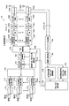
- the user apparatus 10 is configured as a two-reception antenna system having two antennas 101A and 102B.
- User apparatus 10 includes duplexers 102A and 102B, RF receiving circuits 104A and 104B, FFT units 106A and 106B, reception timing estimation unit 108, control channel decoding unit 110, PMI selection and CQI estimation unit 112, delay
- the circuit 114 includes a demodulation PMI accumulation unit 116, a demodulation PMI calculation unit 118, a channel estimation unit 120, a data channel signal detection unit 122, and a channel decoding unit 124.
- the RF receiving circuit 104A (104B) receives a signal from the base station via the receiving antenna 101A (101B) and the duplexer 102A (102B), and converts the received signal into a baseband digital signal. Signal processing. This signal processing may include, for example, power amplification, band limiting, and analog to digital conversion. Further, the RF reception circuit 104A (104B) outputs the signal-processed reception signal to the FFT unit 106A (106B) and the reception timing estimation unit 108.
- the reception timing estimation unit 108 estimates the reception timing of the signal-processed reception signal input from the RF reception circuits 104A and 104B. For this estimation, a cyclic prefix (CP) assigned by the base station may be used. The estimated reception timing is notified to the FFT units 106A and 106B.
- CP cyclic prefix
- the FFT unit 106A (106B) performs Fourier transform on the reception signal input from the RF reception circuit 104A (104B) based on the reception timing notified from the reception timing estimation unit 108. Further, FFT section 106A (106B) outputs the received signal subjected to Fourier transform to control channel decoding section 110, PMI selection and CQI estimation section 112, channel estimation section 120, and data channel signal detection section 122.
- the control channel decoding unit 110 receives the Fourier-transformed received signal from the FFT unit 106A (106B), decodes the control channel included in the received signal, and data related to the PMI information used by the base station for signal transmission To extract. This data is necessary when demodulating the received signal. Specifically, this data indicates whether the PMI information used in the base station is PMI information fed back from the user apparatus or an explicit PMI number of the PMI information when other PMI information is used. Indicates which one. In the case of the explicit PMI number, the user apparatus 10 performs channel estimation of the received signal from the base station using the PMI information notified from the base station instead of the fed back PMI information.
- Control channel decoding section 110 outputs the extracted PMI information to demodulation PMI calculation section 118.
- the PMI selection and CQI estimation unit 112 measures the reception quality using the reference signal in the reception signal input from the FFT unit 106A (106B), generates channel quality information (Channel Quality Indicator: CQI), and generates PMI information Set (select). As a result, a PMI suitable for the radio propagation status at that time is generated. Further, the PMI selection and CQI estimation unit 112 outputs the generated PMI information and the set CQI to the delay circuit 114.
- CQI Channel Quality Indicator
- the delay circuit 114 receives the PMI information from the PMI selection and CQI estimation unit 112 and acquires a predetermined delay amount through, for example, high layer signaling from the base station.
- the delay circuit 114 delays the input PMI information by a predetermined delay amount and outputs the delayed PMI information to the demodulation PMI accumulation unit 116.
- the demodulation PMI accumulation unit 116 receives the PMI information from the delay circuit 114 and stores the input PMI information. Further, the demodulation PMI accumulation unit 116 can output the stored PMI information to the demodulation PMI calculation unit 118.
- the demodulation PMI calculation unit 118 receives the PMI information from the control channel decoding unit 110, and determines the PMI information used for demodulation based on the input PMI information. When the PMI information indicates that the PMI information fed back by the user apparatus in the base station is used, the demodulation PMI calculation unit 118 acquires the PMI information from the demodulation PMI storage unit 116. When the PMI information is an explicit PMI number, the demodulation PMI calculation unit 118 calculates PMI information to be used for demodulation based on the PMI number. Further, demodulation PMI calculation section 118 outputs the acquired or calculated PMI information to channel estimation section 120.
- the channel estimation unit 120 performs channel estimation on the received signal after the Fourier transform input from the FFT units 106A and 106B using the PMI information input from the demodulation PMI calculation unit, and the result is detected as a data channel signal. To the unit 122.
- the data channel signal detection unit 122 demodulates the signals input from the FFT units 106A and 106B using the channel estimation result input from the channel estimation unit 120.
- the demodulated signal is output from the data channel signal detection unit 122 and input to the channel decoding unit 124.
- the channel decoding unit 124 performs channel decoding on the demodulated signal input from the data channel signal detection unit 122 and reproduces the signal transmitted from the base station.
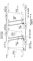
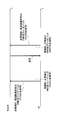
- PMI1 is fed back from the user apparatus (UE) to the base station (NodeB) at time t1.
- the PMI1 is generated by the user apparatus as a precoding matrix indicator indicating a precoding matrix suitable for the downlink based on the reception quality of the reference signal in the received signal received from the base station.
- the user apparatus transmits PMI1 and simultaneously stores PMI1 in the demodulation PMI accumulation unit in the user apparatus.
- the PMI 1 stored in the PMI accumulation unit is then referred to when the user apparatus receives data from the base station, and is used for processing such as data decoding.
- the base station When the base station receives PMI1 at time t2 when a predetermined delay ⁇ has elapsed from time t1, the base station decodes the received PMI1 to obtain a precoding matrix.
- This precoding matrix is assigned an index of PMI1 and is stored in the PMI accumulation unit in the base station.
- time T necessary for the various processes elapses from reception of PMI1 to storage of PMI1.
- the base station transmits a signal to the user apparatus that has fed back PMI1 at time t3.
- the base station refers to the PMI accumulation unit, acquires PMI1 to be used for transmission to this user apparatus, and weights each stream of the signal to be transmitted using a precoding matrix corresponding to PMI1.
- the base station performs predetermined signal processing such as signal multiplexing and transmits the signal to the user apparatus.
- the user apparatus receives the signal.
- the user apparatus decodes the signal using PMI1 stored in its own PMI accumulation unit. In this case, since the PMI information used in the base station is PMI1, and the PMI information used in the user apparatus is also PMI1, normal reception is performed.
- PMI1 is stored in the PMI accumulating unit of the base station (as PMI information for the user apparatus). After being weighted, a signal is transmitted to the user equipment. Similarly to the above, since the user apparatus knows that the PMI information to be used is PMI1, normal reception is performed.
- the user apparatus feeds back PMI2 different from PMI1.
- the change (update) from PMI1 to PMI2 is necessary due to a change in the radio propagation status or the like, and PMI2 is PMI information that the user apparatus determines to be optimal at that time.
- the user apparatus stores the PMI2 in its own PMI accumulation unit almost simultaneously with the transmission of the PMI2.
- the feedback of the PMI information may be periodically performed using the PUCCH, or may be performed using the PUSCH in response to a request from the base station.
- the fed back PMI2 is received by the base station. Thereafter, the PMI2 is decoded and the like, and after the time T has elapsed since the reception of the PMI2, the PMI2 is stored in the PMI accumulation unit of the base station.
- PMI2 is used for weighting, and transmission from the base station to the user apparatus is performed. For example, when transmitted from the base station at time t11 and received by the user apparatus at time t12, PMI2 is used in the base station, and PMI2 is also used in the user apparatus. Therefore, the user device is successfully received.
- the base station transmits a signal to the user apparatus before the time T has elapsed after receiving the PMI2, the PMI1 is still stored in the PMI accumulation unit of the base station. PMI1 is used.
- the user apparatus that receives the signal stores PMI2 in its own PMI accumulation unit, and thus demodulates the received signal using PMI2.
- the base station transmits before the update of the PMI information is completed, there is a problem in that the PMI information does not match between the base station and the user apparatus.
- the PMI information selected by the PMI selection and CQI selection unit 112 is input to the demodulation PMI accumulation unit 116 with a delay of a predetermined delay amount (T + 2 ⁇ ) by the delay circuit 114.
- PMI1 is stored in the PMI accumulating unit at the time point (t1) when PMI1 is fed back from the user apparatus, whereas as shown in FIG. 3, the user apparatus 10 according to the present embodiment of the present invention is used.
- the PMI 1 is stored in the demodulation PMI accumulating unit 116 after a predetermined delay amount (T + 2 ⁇ ) from the time t 1.
- the PMI selection and CQI estimation unit 112 of the user apparatus 10 detects that the PMI information should be changed from PMI1 to PMI2, and also when the PMI2 is fed back to the base station, it is similarly delayed by a predetermined delay amount ( The PMI information in the demodulation PMI storage unit 116 is updated to PMI2 after a delay of T + 2 ⁇ from t7.
- the base station transmits a signal to the user apparatus 10 at time t9
- the update to PMI2 is not finished at time t9, so PMI1 is used and the signal to the user apparatus 10 is transmitted. Is sent.
- demodulation PMI accumulating unit 116 of user apparatus 10 stores PMI1. This is because the delay circuit 114 does not immediately update to PMI2 at time t7 when the user apparatus 10 feeds back PMI2, but causes a delay of T + 2 ⁇ . Therefore, the PMI1 used by the base station matches the PMI1 stored in the demodulation PMI accumulation unit 116 of the user apparatus 10, and the user apparatus 10 can receive appropriately.
- the base station that has received the update of the PMI information transmits using the PMI information before the update before completing the process for the update. Even in this case, the PMI information can be matched between the base station and the user apparatus, and thus communication failure due to the PMI information mismatch can be prevented.
- the time T required for decoding the PMI information or the like may be determined in advance between the base station and the user apparatus as a constant value, and may vary depending on the amount of signal processing in the base station.
- the notification may be made by high layer signaling.
- the signal propagation delay ⁇ may be calculated based on the subband frame number used for feedback of the PMI information. 2 and 3, for the sake of convenience, the propagation delay ⁇ is the same for both upstream transmission and downstream transmission, but it may be different.
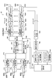
- FIG. 4 is a schematic diagram illustrating a configuration of a base station according to the second embodiment of the present invention.
- the base station 40 is configured as an eight antenna system having eight antennas 402A to 402H.
- the base station 40 includes N buffers 414 1 to 412 N , N PMI information multiplexing units 414 1 to 414 N , a scheduler 416, a channel encoding unit 418, a data modulation unit 420, and precoding.
- Matrix (PM) multiplication unit 422 common reference signal multiplexing units 424A to 424H, fast inverse Fourier transform (IFFT) units 426A to 426H, CP adding units 428A to 428H, RF transmission circuits 430A to 430H, duplexers 404A to 404H, antenna combining section 406, demodulation / decoding section 408, control channel feedback PMI / frame number storage section 432, data channel feedback PMI / frame number storage section 434, PMI / CQI selection section 436, including.
- IFFT fast inverse Fourier transform
- Buffers 412 1 to 412 N store transmission data to be transmitted to each of N user apparatuses (not shown) existing in the cell of base station 40.
- the PMI information multiplexing units 414 1 to 414 N are connected to the corresponding N buffers 411 1 to 412 N , respectively, and input corresponding transmission data. Also, the PMI information multiplexing units 414 1 to 414 N receive PMI information from a PMI / CQI selection unit 436, which will be described later, and multiplex them on the shared data channels of the transmission data respectively input from the buffers 411 1 to 412 N. Thus, a transmission signal corresponding to each user apparatus is generated.
- Modulation scheme / coding rate selection section 410 receives CQI from PMI / CQI selection section 436 (described later), and based on the CQI, modulation scheme and coding rate optimum for transmission from base station 40 to the user apparatus. Select. Based on the selection result, modulation scheme / coding rate selection section 410 generates modulation method information indicating the selected modulation method, and outputs the modulation method information to data modulation section 420. Furthermore, based on the selection result, modulation scheme / coding rate selection section 410 generates scheme information indicating the selected channel coding scheme, and outputs the scheme information to channel coding section 418.
- the scheduler 416 receives transmission signals transmitted from the PMI information multiplexing units 414 1 to 414 N to N user apparatuses, and allocates each transmission signal to a radio resource.
- the channel coding unit 418 receives a transmission signal from the scheduler 416 and receives system information indicating the channel coding system from the modulation system / coding rate selection unit 410. Further, the channel coding unit 418 performs channel coding on the transmission signal by a method indicated by the method information. Further, channel coding section 418 outputs the channel-coded transmission signal to data modulation section 420.
- the data modulation unit 420 receives a channel-coded transmission signal from the channel coding unit 418 and receives modulation method information indicating a modulation method from the modulation scheme / coding rate selection unit 410. Data modulation section 420 modulates the input transmission signal by the modulation method indicated by the modulation method information. Further, the data modulation unit 420 outputs the modulated transmission signal to the PM multiplication unit 422.
- PM multiplication section 422 receives the modulation signal from data modulation section 420, duplicates the input signal, and generates eight transmission signals equal to the number of antennas. That is, eight transmission signals transmitted from each of the eight antennas 402A to 402H are generated.
- the PM multiplication unit 422 has a function as a distributor.
- PM multiplier 422 receives PMI information from PMI / CQI selector 436 and multiplies the generated transmission signal by a precoding matrix.
- the shared data channel is transmitted from the eight antennas 402A to 402H by a directional beam having strong directivity in the direction in which the user apparatus that is the transmission destination is located.
- Each of the eight transmission signals multiplied by the precoding matrix generated in the PM multiplier 422 is then output to the common reference signal multiplexers 424A to 424H.
- Each of the common reference signal multiplexing units 424A to 424H multiplexes the common reference signal to the transmission signal input from the PM multiplication unit 422, and outputs the transmission signal obtained by multiplexing to the corresponding IFFT units 426A to 426H.
- IFFT sections 426A to 426H perform fast inverse Fourier transform on the transmission signals respectively input from common reference signal multiplexing sections 424A to 424H, and output the converted transmission signals to CP adding sections 428A to 428H, respectively.
- CP assigning sections 428A to 428H add a cyclic prefix (CP) to the input signal, and output the transmission signals to which the CP is added to RF transmitting circuits 430A to 430H, respectively.
- the RF transmission circuits 430A to 430H perform processing (digital / analog conversion, band limitation, power amplification, etc.) for transmitting the input signal.
- the processed signal is transmitted from antennas 402A to 402H via duplexers 404A to 404H.
- the output unit of the base station 40 is configured by the elements from the buffers 412 1 to 412 N to the RF transmission circuits 430A to 430H described above. Next, elements constituting the receiving unit will be described. In the following description, the case of transmission to one user apparatus is illustrated.
- the antenna combining unit 406 inputs signals transmitted from the user apparatus (received signals for the base station 40) from the antennas 402A to 402H via the duplexers 404A to 404H. Further, antenna combining section 406 combines these signals and outputs the combined signal to demodulation / decoding section 408.
- the demodulation / decoding unit 408 demodulates / decodes the combined signal input from the antenna combining unit 406 by a predetermined demodulation / decoding method. Also, the demodulation / decoding unit 408 uses PMI information fed back using an uplink physical control channel (PUCCH), CQI corresponding to the PMI information, and feedback thereof from the demodulated / decoded signals. The frame number of the frame (that is, the time of feedback), the PMI information fed back using the uplink data channel (PUSCH), the CQI corresponding to this PMI information, and the frame number of the frame used for the feedback Extract.
- PUCCH uplink physical control channel
- demodulation / decoding section 408 outputs PMI information, CQI and frame number of PUCCH to control channel feedback PMI / CQI / frame number storage section 432 (hereinafter referred to as storage section 432), and PSCH PMI information, CQI. , And the frame number are output to the data channel feedback PMI / CQI / frame number accumulating unit 434 (hereinafter referred to as accumulating unit 434).
- the accumulation unit 432 receives the PMI information, CQI, and frame number of the control channel (PUCCH) from the demodulation / decoding unit 408 and stores them. Further, the accumulation unit 432 can output the stored PMI information, CQI, and frame number of the PUCCH to the PMI / CQI selection unit 436.
- the accumulation unit 434 receives the PMI information, CQI, and frame number of the data channel (PUSCH) from the demodulation / decoding unit 408 and stores them. Further, the accumulation unit 434 can output the stored PSCH PMI information, CQI, and frame number to the PMI / CQI selection unit 436.
- the PMI / CQI selection unit 436 inputs the PMI information, CQI, and frame number of the control channel (PUCCH) from the storage unit 432. Also, the PMI / CQI selection unit 436 receives the PMI information, CQI, and frame number of the data channel (PUSCH) from the storage unit 434. Furthermore, the PMI / CQI selection unit 436 can select which PMI information should be used based on the input PMI information and the frame number. This selection will be described later.
- the PMI / CQI selection section 436 outputs the selected PMI information to the PMI multiplexing sections 414 1 to 414 N and the PM multiplication section 422, and selects the CQI corresponding to the selected PMI information as the modulation scheme / coding rate selection. Output to the unit 410.
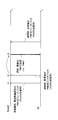
- the user apparatus performs feedback of non-periodic frequency selective PMI1 using PUSCH at time t1. That is, there is a request from the base station to feed back PMI information including PMI information related to a predetermined subband, and in response to the request, feedback of PMI information is performed at time t1.
- the user apparatus feeds back a broadband (common to all bands) PMI2 as feedback of periodic PMI information using PUCCH. That is, in the illustrated example, it is agreed between the user apparatus and the base station that wideband PMI information should be fed back at a constant cycle using PUCCH, and feedback according to this agreement is performed at time t2. It is done in When receiving the PMI2, the base station performs a predetermined process to acquire the PMI2, and updates the PMI information in the PMI accumulation unit to the PMI2.
- the base station uses the updated PMI information. That is, as a rule, the latest PMI information is used. In the illustrated example, PMI2 is used, and the frequency selective PMI information using the PUSCH requested by the base station is not used. Therefore, the base station cannot use the frequency-selective PMI information even though it has requested it. Therefore, there arises an inconvenience that more optimal weighting cannot be performed.
- PMI2 fed back using PUCCH at time t2 is stored as PMI-B in accumulating unit 432 (FIG. 4).
- the frame number of the frame used for PMI2 feedback is also stored in the storage unit 432.
- the L value is 0 or more. If it is 0 or more, PMI-A is selected, and if it is less than 0, PMI-B is selected.
- a and b are forgetting factors, and may be appropriately determined according to, for example, a radio propagation situation. According to such a selection, the feedback of PMI1 through PUSCH can be preferentially used even when the feedback of PMI2 through PUCCH precedes.
- the user apparatus can feed back frequency selective PMI (PMI for each subband) information as PMI-A, and the base station 40 can use these to more appropriately Scheduling can be performed.
- the base station 40 even when feedback of frequency selective PMI information using PUSCH precedes feedback of PMI information common to all bands using PUCCH, it is possible to preferentially use the PMI information fed back through the PUSCH over the latest PMI information fed back through the PUCCH. Also, the latest PMI information can be used when it is assumed that the time difference is large and the radio propagation situation has changed significantly. Therefore, according to the base station 40 according to the present embodiment, an effect of enabling more preferable scheduling is exhibited. Note that the PMI information to be used may be selected based on the difference between T1 and T2.
- PMI-A may be used instead of PMI-B. That is, when PMI-B is received immediately after receiving PMI-A and the time difference between the two is short, it is assumed that the propagation environment between the base station and the user equipment has not changed so much.
- PMI-A fed back through PUSCH eg, frequency selective
- PUCCH eg, broadband
- the elapsed times T1 and T2 are calculated from the frame number of the frame used for the feedback of the PMI information, the present invention is not limited to this, and the time when the base station grasps the reception of the PMI information may be used as the starting time. That is, any method may be used as long as it is possible to quantitatively determine which of PMI information feedback using PUCCH and PMI information feedback using PUSCH is first.
- PMI information fed back using PUSCH is prioritized
- the present invention is not limited to this, and feedback is performed through PUCCH when feedback using PUSCH is performed after feedback using PUCCH.
- PMI information may be prioritized.
- the base station 40 according to the second embodiment has a control channel feedback PMI / CQI / frame number accumulation unit 432 and a data channel feedback PMI / CQI / frame number accumulation unit 434, and Since PMI information is stored, this can be realized. Also from this, the advantage of the mobile station 40 of this embodiment is understood. Note that the PMI information selected by the base station 40 may be explicitly notified to the user apparatus.
- FIG. 7 is a schematic diagram illustrating a configuration of a base station according to the third embodiment of the present invention.
- the base station 70 according to the third embodiment includes the control channel feedback PMI / CQI / frame number accumulation unit 432 and the data channel feedback of the base station 40 according to the second embodiment. It is mainly different from the base station 40 according to the second embodiment in that instead of the PMI / frame number accumulation unit 434, an all-band common PMI / CQI accumulation unit 732 and a frequency selective PMI / CQI accumulation unit 734 are provided. .
- the difference will be mainly described.
- the demodulation / decoding unit 708 of the base station 70 demodulates and decodes the combined signal input from the antenna combining unit 706 by a predetermined demodulation / decoding method.
- the demodulating / decoding unit 708 also uses PMI information (wideband PMI information) common to all bands representing the channel quality of the entire system band, and the channel used for feedback of the PMI information, among the demodulated and decoded signals. Average channel quality information (CQI). Further, demodulation / decoding section 708 extracts frequency selective PMI information (PMI information for each subband) and an average CQI of the channel used for feedback of this PMI information.
- PMI information wideband PMI information
- CQI Average channel quality information
- demodulation / decoding section 708 extracts frequency selective PMI information (PMI information for each subband) and an average CQI of the channel used for feedback of this PMI information.
- the demodulation / decoding unit 708 outputs the PMI information common to all bands and the average CQI related thereto to the all-band common PMI / CQI accumulating unit 732, and outputs the frequency selective PMI information and the average CQI related thereto. Output to frequency selective PMI / CQI accumulating unit 734.
- the all-band common PMI / CQI accumulating unit 732 receives the PMI information common to all the bands and the average CQI related thereto from the demodulation / decoding unit 708 and stores them. Further, the all-band common PMI / CQI accumulating unit 732 can output the stored all-band common PMI information and the average CQI related thereto to the PMI / CQI selecting unit 736.
- the frequency selective PMI / CQI accumulating unit 734 receives the frequency selective PMI information and the average CQI related thereto from the demodulation / decoding unit 708 and stores them. Further, the frequency selective PMI / CQI accumulating unit 734 can output the stored frequency selective PMI information and the average CQI related thereto to the PMI / CQI selecting unit 736.
- the PMI / CQI selection unit 736 inputs the PMI information common to all bands and the average CQI related thereto from the all-band common PMI / CQI storage unit 732. Also, the PMI / CQI selection unit 736 receives the frequency selective PMI information and the average CQI related thereto from the frequency selective PMI / CQI storage unit 734. Further, the PMI / CQI selection unit 736 can select which of PMI information common to all bands and frequency selective PMI information should be used based on the two average CQIs input.
- the X value may be 0 dB, for example.
- the PMI / CQI selection unit 736 outputs the selected PMI information to the PMI information multiplexing units 714 1 to 714 N and the PM multiplication unit 722, and selects the CQI corresponding to the selected PMI information as a modulation scheme / coding rate selection. Output to the unit 710.
- the PMI / CQI selection unit 736 compares two average CQIs and selects PMI information based on the comparison result. Therefore, transmission from the base station 70 to the user apparatus is not limited to the latest PMI information, but PMI information fed back through a channel with good radio propagation conditions is used. As a result, the frequency with which the user apparatus erroneously receives the PMI information used in the base station 70 is reduced, and the mismatch of PMI information between the base station 70 and the user apparatus is reduced. Note that the PMI information selected by the base station 70 may be explicitly notified to the user apparatus.
- a base station according to the fourth embodiment of the present invention is described.
- the base station according to the fourth embodiment is different from the second embodiment in that the request timing of feedback of aperiodic PMI (preferably frequency selective PMI) information performed from the base station to the user apparatus is adjusted. It is mainly different from the base station 40 according to the form. Hereinafter, the difference will be mainly described.
- aperiodic PMI preferably frequency selective PMI
- the scheduler 416 of the base station 40 determines that the feedback from the user apparatus in response to the request is a periodic feedback.
- the timing for transmitting the request is adjusted so that the request is performed within a predetermined time range including the time point.
- the base station 40 includes a control channel feedback time / period accumulation unit 438 for the user with the user number N and an aperiodic PMI feedback request determination unit for the same user. 440 and a downlink control channel generation unit 442 are further included.
- the control channel feedback time / cycle storage unit 438 stores the feedback time (cycle) for each user. This feedback time is determined when communication is started between the base station 40 and the user apparatus. Based on the success or failure of receiving the PMI information from the user apparatus and the CQI included in the received signal, the feedback request determination unit 440, for example, for the user apparatus, aperiodic frequency selectivity using PUSCH It is determined whether feedback of PMI information should be requested. When the downlink request determination unit 440 determines that the feedback request determination unit 440 should request, the downlink control channel generation unit 442 requests feedback from the user apparatus using the UL grant.
- a control channel is generated for a certain user in the base station 40, it is determined by the feedback request determination unit 440 whether or not a non-periodic feedback of PMI should be requested.
- the feedback request stored in the control channel feedback time / period storage unit 438 corresponding to the user is referred to, and a feedback request is made at an appropriate timing.
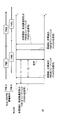
- the predetermined time range may include, for example, zero. That is, as shown in FIG. 9, periodic feedback and feedback in response to a request may be performed at the same time. Further, the predetermined time range may be a range in which the L value is 0 or more in the determination based on Expression (1) using time lapses T1 and T2 (FIG. 6). According to this, even when the base station requests the aperiodic PMI information feedback and the subsequent periodic PMI information feedback is performed, the PMI by the aperiodic feedback is used. Information will be used. In aperiodic feedback, since frequency selective PMI information using PUSCH is usually fed back, this is prioritized and more suitable scheduling is possible.
Landscapes
- Engineering & Computer Science (AREA)
- Computer Networks & Wireless Communication (AREA)
- Signal Processing (AREA)
- Physics & Mathematics (AREA)
- Mathematical Physics (AREA)
- Mobile Radio Communication Systems (AREA)
- Power Engineering (AREA)
- Radio Transmission System (AREA)
Priority Applications (6)
| Application Number | Priority Date | Filing Date | Title |
|---|---|---|---|
| KR1020107014157A KR101525057B1 (ko) | 2008-01-08 | 2008-12-26 | Mimo 방식의 이동체 통신시스템에 있어서의 가중계수 통지방법, 및 이 방법의 사용에 적합한 기지국 및 유저장치 |
| CN2008801239900A CN101911562B (zh) | 2008-01-08 | 2008-12-26 | 多输入多输出方式的移动体通信系统中的加权系数通知方法以及适合使用该方法的基站以及用户装置 |
| CA2707748A CA2707748C (en) | 2008-01-08 | 2008-12-26 | Weighting factor reporting method in a mimo mobile communications system, and base station and user apparatus that are suitable for use in the method |
| BRPI0822233-9A BRPI0822233A2 (pt) | 2008-01-08 | 2008-12-26 | Método para reportar o fator de ponderação em um sistema de comunicações móveis mimo e estação base e aparelho do usuário que são adequados para o uso no método. |
| EP08870210.5A EP2234300B1 (en) | 2008-01-08 | 2008-12-26 | Reliable precoding in MIMO communications systems. |
| US12/810,637 US9130616B2 (en) | 2008-01-08 | 2008-12-26 | Weighting factor reporting method in a mimo mobile communications system, and base station and user apparatus that are suitable for use in the method |
Applications Claiming Priority (2)
| Application Number | Priority Date | Filing Date | Title |
|---|---|---|---|
| JP2008-001665 | 2008-01-08 | ||
| JP2008001665A JP4652420B2 (ja) | 2008-01-08 | 2008-01-08 | ユーザ装置、送信方法、および移動通信システム |
Publications (1)
| Publication Number | Publication Date |
|---|---|
| WO2009087933A1 true WO2009087933A1 (ja) | 2009-07-16 |
Family
ID=40853055
Family Applications (1)
| Application Number | Title | Priority Date | Filing Date |
|---|---|---|---|
| PCT/JP2008/073774 Ceased WO2009087933A1 (ja) | 2008-01-08 | 2008-12-26 | Mimo方式の移動体通信システムにおける重み係数通知方法、並びにこの方法の使用に好適な基地局およびユーザ装置 |
Country Status (9)
| Country | Link |
|---|---|
| US (1) | US9130616B2 (enExample) |
| EP (2) | EP2234300B1 (enExample) |
| JP (1) | JP4652420B2 (enExample) |
| KR (1) | KR101525057B1 (enExample) |
| CN (2) | CN101911562B (enExample) |
| BR (1) | BRPI0822233A2 (enExample) |
| CA (1) | CA2707748C (enExample) |
| RU (2) | RU2010130429A (enExample) |
| WO (1) | WO2009087933A1 (enExample) |
Cited By (1)
| Publication number | Priority date | Publication date | Assignee | Title |
|---|---|---|---|---|
| EP2589160A4 (en) * | 2010-06-30 | 2014-08-20 | Samsung Electronics Co Ltd | SYSTEMS AND METHOD FOR AN 8-TX CODEBOOK AND FEEDBACK SIGNALING IN WIRELESS 3GPP NETWORKS |
Families Citing this family (11)
| Publication number | Priority date | Publication date | Assignee | Title |
|---|---|---|---|---|
| DK2351445T3 (en) | 2008-10-20 | 2015-10-26 | Interdigital Patent Holdings | carrier Aggregation |
| WO2010148319A1 (en) * | 2009-06-19 | 2010-12-23 | Interdigital Patent Holdings, Inc. | Signaling uplink control information in lte-a |
| CN102244566B (zh) * | 2010-05-11 | 2014-03-12 | 中兴通讯股份有限公司 | 用于多输入多输出系统的下行传输方法和基站 |
| JP5505676B2 (ja) * | 2010-06-18 | 2014-05-28 | 日本電気株式会社 | 無線通信システムにおけるダウンリンク協調マルチポイント送信のためのプリコーディング技法 |
| WO2012153658A1 (ja) | 2011-05-10 | 2012-11-15 | Necカシオモバイルコミュニケーションズ株式会社 | 移動局装置および通信方法、並びにコンピュータプログラム |
| JP5753022B2 (ja) * | 2011-08-15 | 2015-07-22 | 株式会社Nttドコモ | 無線通信システム、無線基地局装置、ユーザ端末及び無線通信方法 |
| US9735848B2 (en) | 2012-10-18 | 2017-08-15 | Kyocera Corporation | Mobile communication system and communication control method |
| EP2938146A4 (en) | 2012-12-19 | 2015-12-30 | Fujitsu Ltd | RADIO COMMUNICATION DEVICE AND RADIO COMMUNICATION METHOD |
| WO2017078338A1 (ko) | 2015-11-03 | 2017-05-11 | 엘지전자 주식회사 | 무선 통신 시스템에서 채널 상태 보고 방법 및 이를 위한 장치 |
| KR102473191B1 (ko) | 2016-03-10 | 2022-12-02 | 삼성전자주식회사 | 안테나를 포함하는 전자 장치 |
| US12126466B2 (en) * | 2022-03-09 | 2024-10-22 | Qualcomm Incorporated | Channel state feedback using demodulation reference signals |
Citations (1)
| Publication number | Priority date | Publication date | Assignee | Title |
|---|---|---|---|---|
| WO2007113923A1 (ja) * | 2006-04-06 | 2007-10-11 | Hitachi Communication Technologies, Ltd. | 無線通信システム、無線基地局装置及び無線端末装置 |
Family Cites Families (13)
| Publication number | Priority date | Publication date | Assignee | Title |
|---|---|---|---|---|
| RU2369017C2 (ru) * | 2003-02-18 | 2009-09-27 | Квэлкомм Инкорпорейтед | Команды мультиплексирования с кодовым разделением в мультиплексном канале с кодовым разделением |
| JP2006033306A (ja) * | 2004-07-15 | 2006-02-02 | Sony Corp | 無線通信装置およびその制御方法 |
| CN1941660A (zh) * | 2005-09-30 | 2007-04-04 | 松下电器产业株式会社 | 多天线无线通信系统中的多用户分集方法及系统 |
| US8498639B2 (en) * | 2007-02-09 | 2013-07-30 | Qualcomm Incorporated | Flexible channel quality indicator reporting |
| TW200901655A (en) * | 2007-03-21 | 2009-01-01 | Interdigital Tech Corp | Method and apparatus for communicating precoding or beamforming information to users in MIMO wireless communication systems |
| US8290079B2 (en) * | 2007-04-19 | 2012-10-16 | Interdigital Technology Corporation | Method and apparatus for precoding validation in wireless communications |
| KR20090130206A (ko) * | 2007-04-20 | 2009-12-18 | 인터디지탈 테크날러지 코포레이션 | Mimo 통신에 대한 효과적인 프리코딩 정보 검증을 위한 방법 및 장치 |
| US20080305745A1 (en) * | 2007-06-05 | 2008-12-11 | Interdigital Technology Corporation | Method and apparatus for supporting uplink transmission of channel quality and coding information in a wireless communication system |
| US8325852B2 (en) * | 2007-06-08 | 2012-12-04 | Samsung Electronics Co., Ltd. | CDD precoding for open loop SU MIMO |
| JP4729537B2 (ja) * | 2007-06-19 | 2011-07-20 | 株式会社エヌ・ティ・ティ・ドコモ | 基地局装置および送信方法 |
| US8630184B2 (en) * | 2007-08-15 | 2014-01-14 | Qualcomm Incorporated | Uplink control channel format |
| KR101476202B1 (ko) * | 2008-01-08 | 2014-12-24 | 엘지전자 주식회사 | 주기적/비주기적 채널상태정보 송수신 방법 |
| CN101217304B (zh) * | 2008-01-10 | 2013-01-30 | 北京邮电大学 | 一种多子信道的多输入多输出预编码处理方法 |
-
2008
- 2008-01-08 JP JP2008001665A patent/JP4652420B2/ja active Active
- 2008-12-26 CN CN2008801239900A patent/CN101911562B/zh active Active
- 2008-12-26 US US12/810,637 patent/US9130616B2/en active Active
- 2008-12-26 EP EP08870210.5A patent/EP2234300B1/en active Active
- 2008-12-26 BR BRPI0822233-9A patent/BRPI0822233A2/pt not_active IP Right Cessation
- 2008-12-26 CN CN201310308676.2A patent/CN103354464B/zh active Active
- 2008-12-26 CA CA2707748A patent/CA2707748C/en active Active
- 2008-12-26 WO PCT/JP2008/073774 patent/WO2009087933A1/ja not_active Ceased
- 2008-12-26 RU RU2010130429/07A patent/RU2010130429A/ru not_active Application Discontinuation
- 2008-12-26 EP EP14183711.2A patent/EP2811661B1/en active Active
- 2008-12-26 KR KR1020107014157A patent/KR101525057B1/ko active Active
-
2012
- 2012-10-08 RU RU2012142555/07A patent/RU2521614C2/ru active
Patent Citations (1)
| Publication number | Priority date | Publication date | Assignee | Title |
|---|---|---|---|---|
| WO2007113923A1 (ja) * | 2006-04-06 | 2007-10-11 | Hitachi Communication Technologies, Ltd. | 無線通信システム、無線基地局装置及び無線端末装置 |
Non-Patent Citations (2)
| Title |
|---|
| "Physical layer procedures (Chapter 7.2 - UE procedure for reporting channel quality indication (CQI), precoding matrix indicator (PMI) and rank)", 3GPP TS 36.213 V8.0.0, September 2007 (2007-09-01), pages 11, XP050377555 * |
| SHARP: "Clarification of CQI/PMI/rank reporting mechanisms on PUCCH/PUSCH", RL-074661, 9 November 2007 (2007-11-09), XP050108140 * |
Cited By (4)
| Publication number | Priority date | Publication date | Assignee | Title |
|---|---|---|---|---|
| EP2589160A4 (en) * | 2010-06-30 | 2014-08-20 | Samsung Electronics Co Ltd | SYSTEMS AND METHOD FOR AN 8-TX CODEBOOK AND FEEDBACK SIGNALING IN WIRELESS 3GPP NETWORKS |
| KR101854182B1 (ko) * | 2010-06-30 | 2018-05-04 | 삼성전자주식회사 | 3gpp 무선 네트워크에서 8-tx 코드북 및 피드백 시그널링을 위한 시스템 및 방법 |
| KR20180049167A (ko) * | 2010-06-30 | 2018-05-10 | 삼성전자주식회사 | 3gpp 무선 네트워크에서 8-tx 코드북 및 피드백 시그널링을 위한 시스템 및 방법 |
| KR101869281B1 (ko) * | 2010-06-30 | 2018-06-20 | 삼성전자 주식회사 | 3gpp 무선 네트워크에서 8-tx 코드북 및 피드백 시그널링을 위한 시스템 및 방법 |
Also Published As
| Publication number | Publication date |
|---|---|
| CN103354464B (zh) | 2016-12-28 |
| US20110013719A1 (en) | 2011-01-20 |
| CA2707748C (en) | 2016-04-12 |
| JP4652420B2 (ja) | 2011-03-16 |
| US9130616B2 (en) | 2015-09-08 |
| EP2811661B1 (en) | 2016-07-20 |
| EP2811661A1 (en) | 2014-12-10 |
| CN101911562B (zh) | 2013-08-21 |
| CN101911562A (zh) | 2010-12-08 |
| RU2012142555A (ru) | 2014-04-20 |
| EP2234300A4 (en) | 2014-07-09 |
| EP2234300B1 (en) | 2015-10-21 |
| RU2521614C2 (ru) | 2014-07-10 |
| RU2010130429A (ru) | 2012-02-20 |
| BRPI0822233A2 (pt) | 2015-06-23 |
| CN103354464A (zh) | 2013-10-16 |
| KR20100097187A (ko) | 2010-09-02 |
| KR101525057B1 (ko) | 2015-06-18 |
| JP2009164975A (ja) | 2009-07-23 |
| EP2234300A1 (en) | 2010-09-29 |
| CA2707748A1 (en) | 2009-07-16 |
Similar Documents
| Publication | Publication Date | Title |
|---|---|---|
| JP4652420B2 (ja) | ユーザ装置、送信方法、および移動通信システム | |
| RU2501163C1 (ru) | Базовая станция (варианты), способ передачи (варианты) и система мобильной связи | |
| US7139328B2 (en) | Method and apparatus for closed loop data transmission | |
| US8000405B2 (en) | Transmission method, transmission apparatus and communication system | |
| KR101913988B1 (ko) | 채널 추정 향상들 | |
| US20160112104A1 (en) | Methods and systems for combined cyclic delay diversity and precoding of radio signals | |
| US9667457B2 (en) | Radio communication device and signal processing method | |
| JP2007089165A (ja) | 多重アンテナを使用する無線通信システムにおけるチャネル補正装置及び方法 | |
| JP2008506330A (ja) | 多重アンテナシステムにおけるビームフォーミング装置及び方法 | |
| CN102792623A (zh) | 码本控制方法、基站装置以及移动台装置 | |
| JP5797577B2 (ja) | 無線通信基地局装置、無線通信端末装置及びフィードバック方法 | |
| EP2983318B1 (en) | Mobile station, base station, and communication control method | |
| KR20150028335A (ko) | 무선 통신 장치, 및 harq 응답의 송신 방법 및 수신 방법 | |
| WO2011090105A1 (ja) | 移動局装置、チャネル情報フィードバック方法 | |
| CN109787727B (zh) | 一种用于无线通信的用户设备、基站中的方法和装置 | |
| JP4800438B2 (ja) | 基地局装置および通信方法 | |
| CN107431576B (zh) | 预编码信息的获取方法和设备 | |
| JP7260327B2 (ja) | 無線通信システム、送信局及び受信局 | |
| WO2024070445A1 (ja) | 複数のアクセスポイント装置を介して無線デバイスと通信する処理装置 | |
| JP2008301418A (ja) | 無線通信装置 |
Legal Events
| Date | Code | Title | Description |
|---|---|---|---|
| WWE | Wipo information: entry into national phase |
Ref document number: 200880123990.0 Country of ref document: CN |
|
| 121 | Ep: the epo has been informed by wipo that ep was designated in this application |
Ref document number: 08870210 Country of ref document: EP Kind code of ref document: A1 |
|
| WWE | Wipo information: entry into national phase |
Ref document number: 2707748 Country of ref document: CA |
|
| WWE | Wipo information: entry into national phase |
Ref document number: 2038/KOLNP/2010 Country of ref document: IN |
|
| ENP | Entry into the national phase |
Ref document number: 20107014157 Country of ref document: KR Kind code of ref document: A |
|
| WWE | Wipo information: entry into national phase |
Ref document number: MX/A/2010/007333 Country of ref document: MX |
|
| NENP | Non-entry into the national phase |
Ref country code: DE |
|
| WWE | Wipo information: entry into national phase |
Ref document number: 2008870210 Country of ref document: EP |
|
| WWE | Wipo information: entry into national phase |
Ref document number: DZP2010000504 Country of ref document: DZ |
|
| WWE | Wipo information: entry into national phase |
Ref document number: 2010130429 Country of ref document: RU |
|
| WWE | Wipo information: entry into national phase |
Ref document number: 12810637 Country of ref document: US |
|
| ENP | Entry into the national phase |
Ref document number: PI0822233 Country of ref document: BR Kind code of ref document: A2 Effective date: 20100705 |