EP2234300B1 - Reliable precoding in MIMO communications systems. - Google Patents
Reliable precoding in MIMO communications systems. Download PDFInfo
- Publication number
- EP2234300B1 EP2234300B1 EP08870210.5A EP08870210A EP2234300B1 EP 2234300 B1 EP2234300 B1 EP 2234300B1 EP 08870210 A EP08870210 A EP 08870210A EP 2234300 B1 EP2234300 B1 EP 2234300B1
- Authority
- EP
- European Patent Office
- Prior art keywords
- pmi
- base station
- user apparatus
- pmi information
- information
- Prior art date
- Legal status (The legal status is an assumption and is not a legal conclusion. Google has not performed a legal analysis and makes no representation as to the accuracy of the status listed.)
- Active
Links
Images


Classifications
-
- H—ELECTRICITY
- H04—ELECTRIC COMMUNICATION TECHNIQUE
- H04B—TRANSMISSION
- H04B7/00—Radio transmission systems, i.e. using radiation field
- H04B7/02—Diversity systems; Multi-antenna system, i.e. transmission or reception using multiple antennas
- H04B7/04—Diversity systems; Multi-antenna system, i.e. transmission or reception using multiple antennas using two or more spaced independent antennas
- H04B7/0413—MIMO systems
- H04B7/0417—Feedback systems
-
- H—ELECTRICITY
- H04—ELECTRIC COMMUNICATION TECHNIQUE
- H04B—TRANSMISSION
- H04B7/00—Radio transmission systems, i.e. using radiation field
- H04B7/02—Diversity systems; Multi-antenna system, i.e. transmission or reception using multiple antennas
- H04B7/04—Diversity systems; Multi-antenna system, i.e. transmission or reception using multiple antennas using two or more spaced independent antennas
- H04B7/0413—MIMO systems
- H04B7/0456—Selection of precoding matrices or codebooks, e.g. using matrices antenna weighting
-
- H—ELECTRICITY
- H04—ELECTRIC COMMUNICATION TECHNIQUE
- H04B—TRANSMISSION
- H04B7/00—Radio transmission systems, i.e. using radiation field
- H04B7/02—Diversity systems; Multi-antenna system, i.e. transmission or reception using multiple antennas
- H04B7/04—Diversity systems; Multi-antenna system, i.e. transmission or reception using multiple antennas using two or more spaced independent antennas
- H04B7/06—Diversity systems; Multi-antenna system, i.e. transmission or reception using multiple antennas using two or more spaced independent antennas at the transmitting station
- H04B7/0613—Diversity systems; Multi-antenna system, i.e. transmission or reception using multiple antennas using two or more spaced independent antennas at the transmitting station using simultaneous transmission
- H04B7/0615—Diversity systems; Multi-antenna system, i.e. transmission or reception using multiple antennas using two or more spaced independent antennas at the transmitting station using simultaneous transmission of weighted versions of same signal
- H04B7/0619—Diversity systems; Multi-antenna system, i.e. transmission or reception using multiple antennas using two or more spaced independent antennas at the transmitting station using simultaneous transmission of weighted versions of same signal using feedback from receiving side
- H04B7/0636—Feedback format
- H04B7/0639—Using selective indices, e.g. of a codebook, e.g. pre-distortion matrix index [PMI] or for beam selection
-
- H—ELECTRICITY
- H04—ELECTRIC COMMUNICATION TECHNIQUE
- H04L—TRANSMISSION OF DIGITAL INFORMATION, e.g. TELEGRAPHIC COMMUNICATION
- H04L25/00—Baseband systems
- H04L25/02—Details ; arrangements for supplying electrical power along data transmission lines
- H04L25/0202—Channel estimation
- H04L25/0204—Channel estimation of multiple channels
-
- H—ELECTRICITY
- H04—ELECTRIC COMMUNICATION TECHNIQUE
- H04B—TRANSMISSION
- H04B1/00—Details of transmission systems, not covered by a single one of groups H04B3/00 - H04B13/00; Details of transmission systems not characterised by the medium used for transmission
- H04B1/69—Spread spectrum techniques
- H04B1/707—Spread spectrum techniques using direct sequence modulation
- H04B1/7097—Interference-related aspects
- H04B1/711—Interference-related aspects the interference being multi-path interference
- H04B1/7115—Constructive combining of multi-path signals, i.e. RAKE receivers
-
- H—ELECTRICITY
- H04—ELECTRIC COMMUNICATION TECHNIQUE
- H04B—TRANSMISSION
- H04B2201/00—Indexing scheme relating to details of transmission systems not covered by a single group of H04B3/00 - H04B13/00
- H04B2201/69—Orthogonal indexing scheme relating to spread spectrum techniques in general
- H04B2201/707—Orthogonal indexing scheme relating to spread spectrum techniques in general relating to direct sequence modulation
- H04B2201/7097—Direct sequence modulation interference
- H04B2201/709709—Methods of preventing interference
Definitions
- the present invention generally relates to MIMO (multi input multi output) mobile communications systems, and more particularly relates to weighting factor reporting methods in MIMO, and base stations and user apparatuses that are suitable for use in the methods.
- MIMO multi input multi output
- a multiple input and multiple output (MIMO) communications scheme which uses multiple antennas between a base station and a user apparatus.
- a directional beam may be utilized which is formed by multiplying multiple streams, generated by duplicating a signal stream to be transmitted, with weighting factors corresponding to the streams, making it possible to improve transmission speed and quality of a transmission signal.
- the weighting factor used here is called a pre-encoding vector or a pre-encoding matrix.
- the user apparatus sets a pre-encoding matrix based on a measurement of a common reference signal, generates pre-encoding matrix indicator (PMI) information which indicates the content of this pre-encoding matrix, and transmits (feeds back) the generated PMI information to the base station.
- PMI pre-encoding matrix indicator
- This feedback is performed periodically using a physical uplink control channel (PUCCH), or performed using a physical uplink shared channel (PUSCH) in response to a request from the base station.
- PUCCH physical uplink control channel
- PUSCH physical uplink shared channel
- the PMI information includes information on a wideband PMI (a PMI common to the whole bandwidth) which indicates the whole bandwidth allowed for a communications system, and information on a PMI for each sub-band within the bandwidth (a frequency selective PMI) (See 3GPP, RF-074820, "Investigation on PMI Indication Schemes for Single-User MIMO Pre-encoding in E-UTRA Downlink", for example.)
- the common channel may be called a data channel.
- the base station utilizes the PMI information received from the user apparatus to process a signal to be transmitted to the user apparatus, and utilizes a directional beam suitable for the user apparatus to transmit the signal.
- PMI information received from the user apparatus to process a signal to be transmitted to the user apparatus, and utilizes a directional beam suitable for the user apparatus to transmit the signal.
- the base station may erroneously receive the PMI information fed back from the user apparatus, so that the PMI information may not be shared between the base station and the user apparatus.
- the base station ends up using PMI information which is different from the fed back PMI information
- the user apparatus ends up receiving a signal processed using PMI information which is different from PMI information fed back by itself, making it not possible to properly process a downlink shared channel.
- the PMI information used may not match between the base station and the user apparatus. Moreover, between the base station and the user apparatus, it may also be necessary to share more suitable PMI information.
- the object of the present invention is to provide a method of facilitating an effective use of PMI information in MIMO communications involving a feedback of PMI information and a base station and a user apparatus that are suitable for use in the method.
- the present invention provides a user apparatus according to claim 1 and a base station according to claim 3. Additional details of said user apparatus and said base station are provided in claim 2 and claims 4-7, respectively.
- the present invention provides a communications method in a MIMO mobile communications system according to claim 8 and further detailed in claim 9.
- the present invention provides a communications method according to claim 10 and further detailed in claims 11-14.
- the present invention makes it possible to provide a method of facilitating an effective use of PMI information in MIMO communications involving feedback of PMI information and a base station and a user apparatus that are suitable for use in the method.
- the user apparatus 10 includes a two receive antenna system having two antennas 101A, 102B.
- the user apparatus 10 has duplexers 102A, 102B; RF receive circuits 104A, 104B; FFT units 106A, 106B; a receive timing estimator 108; a control channel decoder 110; a PMI selecting and CQI estimating unit 112; a delay circuit 114; a PMI accumulator for demodulation 116; a PMI arithmetic unit for demodulation 118; a channel estimator 120; a data channel signal detector 122; and a channel decoder 124.
- the RF receive circuit 104A (104B) receives a signal from a base station via the receive antenna 101A (101B) and the duplexer 102A (102B), and performs, on the received signal, a predetermined signal process for converting to a base band digital signal.
- the signal process may include power amplification, bandwidth limiting, and analog-to-digital conversion, for example.
- the RF receive circuit 104A (104B) outputs the signal-processed received signal to the FFT unit 106A (106B) and to the receive timing estimator 108.
- the receive timing estimator 108 estimates a receive timing of the signal-processed received signal that is input from the RF receive circuit 104A and 104B. For this estimation, a cyclic prefix (CP) added at the base station may be utilized. The estimated receive timing is reported to the FFT units 106A and 106B.
- CP cyclic prefix
- the FFT unit 106A (106B) Fourier transforms the received signal input from the RF receiving circuit 104A (104B). Moreover, the FFT unit 106A (106B) outputs a Fourier-transformed received signal to the control channel decoder 110, the PMI selecting and CQI estimating unit 112, the channel estimator 120, and the data channel signal detector 122.
- the control channel decoder 110 takes the Fourier-transformed received signal from the FFT unit 106A (106B) and decodes a control channel included in the received signal to extract data on PMI information used by the base station at the time of signal transmission. These data are needed for demodulating the received signal. More specifically, these data indicate whether the PMI information used at the base station is PMI information fed back from the user apparatus, or an explicit PMI number of the PMI information when different PMI information is used. For the explicit PMI number, the user apparatus 10 uses not the fed back PMI information, but PMI information reported from the base station to perform channel estimation on the received signal from the base station.
- the explicit PMI number is reported in a case such that, for various reasons, the base station had to use PMI information different from the PMI information fed back from the user apparatus 10. Except for such a rather irregular case, the fact that the fed back PMI information is being followed is reported.
- the control channel decoder 110 outputs extracted PMI information to the PMI arithmetic unit 118.
- the PMI selecting and CQI estimating unit 112 uses a reference signal within a received signal input from an FFT unit 106A (106B) to measure a received quality, generate a channel quality indicator (CQI), and set (select) PMI information. In this way, a PMI suitable for the radio propagation status at that time is generated. Moreover, the PMI selecting and CQI estimating unit 112 outputs, to the delay circuit 114, the PMI information generated and the CQI set.
- CQI channel quality indicator
- the delay circuit 114 takes, as an input, the PMI information from the PMI selecting and CQI estimating unit 112 and obtains a predetermined delay amount through high-layer signaling, for example, from the base station. Moreover, the delay circuit 114 delays the input PMI information by a predetermined delay amount for outputting to the PMI accumulating unit for demodulation 116.
- the PMI accumulating unit for demodulation 116 takes, as an input, the PMI information from the delay circuit 114, and stores the input PMI information. Moreover, the PMI accumulating unit for demodulation 116 may output the stored PMI information to the PMI arithmetic unit for demodulation 118.
- the PMI arithmetic unit for demodulation 118 takes, as an input, the PMI information from the control channel decoder 110 and determines PMI information to be used for demodulation based on the input PMI information. If the PMI information indicates that the PMI information fed back by the user apparatus has been used at the base station, the PMI arithmetic unit for demodulation 118 obtains PMI information from the PMI accumulating unit for demodulation 116. When the PMI information is an explicit PMI number, the PMI arithmetic unit for demodulation 118 calculates PMI information to be used for demodulation based on the PMI number. Moreover, the PMI arithmetic unit for demodulation 118 outputs obtained or calculated PMI information to the channel estimator 120.
- the channel estimator 120 performs channel estimation on the Fourier-transformed received signal input from the FFT units 106A and 106B using the PMI information input from the PMI arithmetic unit for demodulation and outputs the result to the data channel signal detector 122.
- the data channel signal detector 122 demodulates a signal input from the FFT unit 106A and 106B using a channel estimation result input from the channel estimator 120.
- the demodulated signal which is output from the data channel signal detector 122, is input into the channel decoder 124.
- the channel decoder 124 performs channel decoding on the demodulated signal input from the data channel signal detector 122 to reconstruct a signal transmitted from the base station.
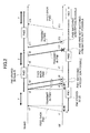
- a PMI is fed back from a user apparatus (UE) to a base station (Node B).
- the PMI1 is generated, prior to the feedback, as a pre-encoding matrix indicator to indicate a pre-encoding matrix suitable for downlink that is determined by the user apparatus based on a received quality of a reference signal within a received signal received from the base station.
- the user apparatus stores a PMI1 in a PMI accumulating unit for demodulation that is within the user apparatus at the same time it transmits the PMI1.
- the PMI1 stored in the PMI accumulating unit is subsequently referred to when the user apparatus receives data from the base station to use in a process such as data decoding, etc.
- the base station When the base station receives a PMI1 at a time t2 which is a predetermined delay ⁇ after time t1, it decodes the received PMI1 to obtain the pre-encoding matrix.
- the pre-encoding matrix has added an indicator PMI1 so as to be stored in the PMI accumulating unit within the base station.
- a time T needed for the various processes elapses from receiving the PMI1 to storing the PMI1.
- the base station transmits a signal to a user apparatus which fed back the PMI1.
- the base station refers to the PMI accumulating unit to obtain the PMI1 to be used in transmitting to this user apparatus, and weights each stream of a signal to be transmitted using a pre-encoding matrix corresponding to the PMI1.
- the base station performs predetermined signal processes such as signal multiplexing to transmit the signal to the user apparatus.
- the user apparatus receives the signal.
- the user apparatus uses the PMI1 stored in its own PMI accumulating unit to decode the signal.
- PMI information used in the base station is PMI1
- the PMI information used in the user apparatus is also PMI1, so that a normal reception is conducted.
- the base station transmits signals to the same user apparatus at a time t5
- the PMI1 is stored (as PMI information for the user apparatus) within the PMI accumulating unit of the base station, weighting using the PMI1 is performed, after which the signal is transmitted to the user apparatus.
- the user apparatus is also aware that the PMI information to be used is PMI1, a normal reception is performed.
- the process continues in which the user apparatus feeds back a PMI2, which is different from the PMI1.
- a change (update) from the PMI1 to the PMI2 is what has become necessary due to a change in a radio propagation condition, etc., where the PMI2 is the PMI information which has been determined to be optimal by the user apparatus at that time.
- the user apparatus stores the PMI2 in its own PMI accumulating unit almost at the same time it transmits the PMI2.
- the feedback of the PMI information may be performed periodically using the PUCCH, or may be performed using the PUSCH in response to a request from the base station.
- the PMI2 fed back is received at the base station. Thereafter, the PMI2 is decoded, etc., and a time T after receiving the PMI2, the PMI2 is stored in the PMI accumulating unit of the base station.
- the PMI2 is used for weighting to transmit from the base station to the user apparatus.
- the PMI2 is used at the base station and also at the user apparatus when transmission is conducted from the base station at a time t11 and reception is conducted at the user apparatus at a time t12.
- the user apparatus succeeds in the reception.
- the PMI information selected at the PMI selecting and the CQI estimating unit 112 ( FIG. 1 ) is input to the PMI accumulating unit for demodulation 116 with a predetermined delay amount (T+2 ⁇ ) using the delay circuit 114.
- the PMI1 is stored in the PMI accumulating unit at the time (t1) the PMI1 is fed back from the user apparatus, whereas, as shown in FIG. 3 , in the user apparatus 10 according to an embodiment of the present invention, the PMI1 is stored in the PMI accumulating unit for demodulation 116 with the predetermined delay amount (T+2 ⁇ ) from the time t1.
- the PMI information is to be changed from the PMI1 to the PMI2 is detected by the PMI selecting and CQI estimating unit 112 of the user apparatus 10, and the PMI information within the PMI accumulating unit for demodulation 116 is updated to the PMI2 with a delay of a predetermined delay amount (a delay of T+2 ⁇ from t7) also in case of feeding back the PMi2 to the base station.
- a predetermined delay amount a delay of T+2 ⁇ from t7
- the PMI accumulating unit 116 for demodulation within the user apparatus 10 stores the PMI1. This is because, due to the delay circuit 114, a delay of T+2 ⁇ occurs without an immediate update to the PMI2 at the time the user apparatus 10 fed back the PMI2.
- a time T which is required for PMI information decoding, etc. may be predetermined as a certain value between the base station and the user apparatus, or may be reported from the base station to the user apparatus using high-layer signaling, for example, as it may change due to an amount of signal processing at the base station.
- the propagation delay ⁇ of the signal may be calculated based on a frame number of a sub-band used for feeding back the PMI information. In FIGS. 2 and 3 , the propagation delay ⁇ is arranged to be the same in both uplink transmission and downlink transmission for convenience, but they may be arranged to be different.
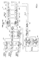
- FIG. 4 is a schematic diagram illustrating a configuration of the base station according to the second embodiment of the present invention.
- the base station 40 is arranged as an 8-antenna system having eight antennas 402A-404H.
- the base station 40 has N buffers 412 1 -412 N , N PMI information multiplexers 414 1 -414 N , a scheduler 416, a channel encoder 418, a data modulator 420, a pre-encoding matrix (PM) multiplying unit 422, common reference signal multiplexers 424A-424H, inverse fast Fourier transform (IFFT) units 426A-426H, CP adders 428A-428H, RF transmit circuits 430A-430H, duplexers 404A-404H, an antenna combiner 406, a demodulator/decoder 408, a control channel feedback PMI and frame number accumulating unit 432, a data channel feedback PMI and frame number accumulating unit 434, and a PMI/CQI selector 436.
- PM pre-encoding matrix
- IFFT inverse fast Fourier transform
- the buffers 412 1 -412 N store transmit data to be transmitted to corresponding N user apparatuses (not shown) that reside within a cell of the base station 40.
- the PMI information multiplexers 414 1 -414 N are respectively connected to the N buffers 411 1 -412 N and take, as inputs, corresponding transmit data sets. Moreover, the PMI information multiplexers 414 1 -414 N take, as inputs, the PMI information sets from the below-described PMI/CQI selector 436 and multiplexes them into shared data channels of transmit data respectively input from the buffers 412 1 -412 N to generate transmit signals corresponding to the user apparatuses.
- the modulation scheme/encoding rate selector 410 takes, as an input, a CQI from the below-described PMI and CQI selector 436, and, based on the CQI, selects a modulation scheme and encoding rate which are optimal for transmission from the base station 40 to the user apparatus. Based on the result of the selection, the modulation scheme/encoding rate selector 410 generates modulation method information which indicates the selected modulation method and outputs modulation method information to the data modulator 420. Moreover, based on the result of the selection, the modulation scheme/encoding rate selector 410 generates scheme information which indicates the selected channel encoding scheme, and outputs the scheme information to the channel encoder 418.
- the scheduler 416 takes, as inputs, transmit signals from the PMI information multiplexers 414 1 -414 N that are to be respectively transmitted to N user apparatuses, and allocates a radio resource to each of the transmit signals.
- the channel encoder 418 takes, as an input, a transmit signal from the scheduler 416 and takes, as an input, scheme information indicating a channel encoding scheme from the modulation scheme/encoding rate selector 410. Moreover, the channel encoder 418 performs channel encoding on the transmit signal using the scheme indicated in the scheme information. Moreover, the channel encoder 418 outputs the channel-encoded transmit signal to the data modulator 420.
- the data modulator 420 takes, as an input, the channel-encoded transmit signal from the channel encoder 418, and takes, as an input, modulation scheme information indicating the modulation scheme from the modulation scheme/encoding rate selector 410 into the data modulator 420. Moreover, the data modulator 420 modulates the input transmit signal with the modulation scheme indicated in the modulation scheme information. Furthermore, the data modulator 420 outputs the modulated transmit signal to the PM multiplying unit 422.
- the PM multiplying unit 422 takes, as an input, the modulated signal from the data modulator 420, and duplicates the input signal to generate eight transmit signals, the number of which is the same as the number of antennas. In other words, eight transmit signals to be transmitted from the corresponding eight antennas 402A-402H are generated. In other words, the PM multiplying unit 422 has a function of a splitter. Moreover, the PM multiplying unit 422 takes, as an input, PMI information from the PMI/CQI selector 436, and multiplies a pre-encoding matrix with the transmit signal generated. In this way, the shared data channel is transmitted from the eight antennas 402A -402H using a directional beam having a strong directivity in a direction at which a user apparatus to be transmitted to is located.
- Each of the eight transmit signals to which the pre-encoding matrix is multiplied that is generated by the PM multiplying unit 422 is then output to the common reference signal multiplexers 424A-424H.
- the common reference signal multiplexers 424A-424H multiplex a common reference signal with the corresponding transmit signals taken from the PM multiplying unit 422 as inputs, and output the transmit signals obtained by the multiplexing to corresponding IFFT units 426A-426H.
- the IFFT units 426A-426H inverse fast Fourier transform transmit signals respectively taken as inputs from the common reference signal multiplexers 424A-424H, and output the transformed respective transmit signals to CP adders 428A-428H.
- the CP adders 428A-428H add cyclic prefixes (CPs) to the input signals and output the respective CP-added transmit signals to the RF transmit circuits 430A- 430H.
- the RF transmit circuits 430A-430H perform processes (digital-analog conversion, bandwidth limiting, power amplification, etc.) for transmitting the corresponding input signals.
- the processed signals are transmitted from the antennas 402A-402H via respective duplexers 404A-404H.
- the antenna combiner 406 takes, as an input from each of antennas 402A to 402H, a signal transmitted from the user apparatus (a received signal for the base station 40) via the duplexers 404A to 404H. Moreover, the antenna combiner 406 combines the signals and outputs the combined signal to the demodulator/decoder 408.
- the demodulator/decoder 408 demodulates/decodes the combined signal taken as an input from the antenna combiner 406. Moreover, the demodulator/decoder 408 extracts, from the demodulated/decoded signal, PMI information fed back using a physical uplink control channel (PUCCH), CQI corresponding to the PMI information, and a frame number of a frame used in the feedback (in other words, a feedback time), PMI information fed back using a physical uplink data channel (PUSCH), CQI corresponding to the PMI information, and a frame number of a frame used in the feedback.
- PUCCH physical uplink control channel
- CQI corresponding to the PMI information a frame number of a frame used in the feedback
- PUSCH physical uplink data channel
- the demodulator/decoder 408 outputs the PUCCH PMI information, the CQI, and the frame number to the control channel feedback PMI/CQI/frame number accumulating unit 432 (below called the accumulating unit 432), and outputs the PUSCH PMI information, the CQI, and the frame number to the data channel feedback PMI/CQI/frame number accumulating unit 434 (below called the accumulating unit 434).
- the accumulating unit 432 takes, as inputs, the control channel (PUCCH) PMI information, the CQI, and the frame number from the demodulator/decoder 408 and stores the same. Moreover, the accumulating unit 432 may output the stored PUCCH PMI information, CQI, and frame number to the PMI/CQI selector 436.
- PUCCH control channel
- the accumulating unit 434 takes, as inputs, the data channel (PUSCH) PMI information, the CQI, and the frame number from the demodulator/decoder 408 and stores the same. Moreover, the accumulating unit 434 may output the stored PUSCH PMI information, CQI, and frame number to the PMI/CQI selector 436.
- PUSCH data channel
- CQI frame number
- CQI frame number
- the PMI/CQI selector 436 takes, as inputs, the control channel (PUCCH) PMI information, the CQI, and the frame number from the accumulating unit 432. Moreover, the PMI/CQI selector 436 takes, as inputs, the data channel (PUSCH) PMI information, the CQI, and the frame number from the accumulating unit 434. Furthermore, the PMI/CQI selector 436 may select which PMI information to be used based on the input PMI information and frame number. This selection is to be described below.
- the PMI/CQI selector 436 outputs the selected PMI information to the PMI multiplexers 414 1 -414 N and the PM multiplying unit 422, and outputs the CQI corresponding to the selected PMI information to the modulation scheme/encoding rate selector 410.
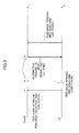
- FIG. 5 For comparison, transmission and reception in a pre-encoding MIMO system between the base station and a user apparatus not having the feature of the user apparatus 10 is described with reference to FIG. 5 .
- a propagation delay ⁇ of a signal is ignored.
- the base station (the base station 40) is to follow PMI information fed back from the user apparatus.
- a user apparatus in communication with a base station (a base station 40) may be a user apparatus 10 according to a first embodiment.
- the user apparatus feeds back aperiodic frequency selective PMI1 using PUSCH at a time t1.
- a request is made from a base station to feed back PMI information including PMI information on a predetermined sub-band, and, in response to the request, the PMI information is fed back at the time t1
- the user apparatus feeds back a wideband PMI2 (which is common to the whole bandwidth) as a feedback of periodic PMI information using the PUCCH.
- a wideband PMI2 which is common to the whole bandwidth
- the base station Upon receiving the PMI2, the base station performs a predetermined process to obtain the PMI2 and update PMI information of the PMI1 accumulating unit to the PMI2.
- the base station uses PMI information updated.
- PMI information updated.
- the most recent PMI information is used.
- the PMI2 is used, but frequency selective PMI information which uses the PUSCH requested by the base station is not used. Therefore, a problem occurs such that, despite the fact that the base station has requested the frequency selective PMI information, it cannot use the same, and, therefore, a more optimal weighting cannot be performed.
- the PMI1 which is fed back at a time t1 and is fed back using the PUSCH, is stored in the accumulating unit 434 ( FIG. 4 ) as PMI-A. Moreover, a frame number of a frame used in feeding back the PMI1 is also stored in the accumulating unit 434.
- the PMI2 fed back using the PUCCH is stored as PMI-B in the accumulating unit 432 ( FIG. 4 ). Moreover, the frame number of the frame used in feeding back the PMI2 is also stored in the accumulating unit 432.
- PMI information selected at the PMI/CQI selector 436 is used. This selection is performed as follows, for example. First, in the PMI/CQI selector 436, T1, which is an elapsed time between a time at which the PMI1 is fed back and a data transmitting time (a downlink transmitting time), and T2, which is an elapsed time between a time at which the PMI2 is fed back and a data transmitting time are calculated. Such a calculation as described above may be performed from a frame number from the accumulators 432 and 434.
- an L value expressed as L a T ⁇ 1 - b T ⁇ 2 0 ⁇ a ⁇ 1 , 0 ⁇ b ⁇ 1 is calculated.
- a and b are forgetting factors. (They may be determined appropriately in accordance with radio propagation conditions, for example.) According to such a selection, even if feedback of the PMI1 throughout the PUSCH precedes feedback of the PMI2 throughout the PUCCH, the feedback of the PMI1 may be used preferentially.
- the user apparatus can feed back frequency selective PMI (PMI for each sub-band) information) as PMI-A, and the base station 40 can perform more appropriate scheduling by utilizing the same.
- the base station 40 according to the present embodiment makes it possible to preferentially use the PMI information fed back through the PUSCH relative to most recent information fed back through the PUCCH when the time difference is small and the radio propagation condition does not change significantly. Moreover, when the time difference is large, and it is anticipated that the radio propagation condition has changed significantly, the most recent PMI information may also be used. Therefore, the base station 40 according to the present embodiment achieves an advantage which makes it possible to perform more suitable scheduling.
- PMI information to be used may be selected based on a difference between T1 and T2. For example, when T1>T2, and T2-T1 is no more than a predetermined time, PMI-A may be used, not PMI-B. In other words, when PMI-B is received immediately after receiving PMI-A and the time difference between the two is short, it is anticipated that the propagation environment between the base station and the user apparatus has not changed much; thus, it is preferable not to use a (e.g., wide band) PMI-B which is fed back via the PUCCH, but to use a (e.g., frequency selective) PMI-A which is fed back via the PUSCH.
- a (e.g., wide band) PMI-B which is fed back via the PUCCH
- a (e.g., frequency selective) PMI-A which is fed back via the PUSCH.
- the elapsed times T1 and T2 have been calculated from the frame number of the frame used in the PMI information feedback; however it is not limited to this, so that a time at which the base station recognizes reception of PMI information may be set as a starting time.
- any method may be used as long as it can be quantitatively determined as to which one of feedback of PMI information using the PUCCH and feedback of PMI information using the PUSCH precedes the other.
- the base station 40 has the control channel feedback PMI/CQI/frame number accumulating unit 432 and the data channel feedback PMI/CQI/ frame number accumulating unit 434 and stores the PMI information for each channel.
- the above also facilitates understanding the advantages of the mobile station 40 of the present embodiment.
- the PMI information selected by the base station 40 may be reported explicitly to the user apparatus.
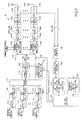
- FIG. 7 is a schematic diagram illustrating a configuration of the base station according to the third embodiment.
- the base station 70 according to the third embodiment primarily differs from the base station 40 according to the second embodiment in that the base station 70 includes, in lieu of the control channel feedback PMI/CQI/frame number accumulating unit 432 and the data channel feedback PMI/frame number accumulating unit 434, a unit for accumulating PMI/CQI, common to the whole bandwidth 732 and a frequency-selective PMI/CQI accumulating unit 734.
- a unit for accumulating PMI/CQI common to the whole bandwidth 732 and a frequency-selective PMI/CQI accumulating unit 734.
- the demodulator/decoder 708 of the base station 70 demodulates/decodes the combined signal input from the antenna combiner 706. Moreover, the demodulator/decoder 708 extracts, from the demodulated and decoded signal, PMI information common to the whole bandwidth (wideband PMI information) that represents a channel quality of the overall system bandwidth, and average channel quality information (CQI) of a channel used in the feedback of the PMI information. Moreover, the demodulator/decoder 708 extracts frequency selective PMI information (PMI information for each sub-band) and an average CQI of a channel used in feeding back the PMI information.
- PMI information common to the whole bandwidth wideband PMI information
- CQI average channel quality information
- the demodulator/decoder 708 outputs, to the unit for accumulating PMI/CQI common to the whole bandwidth 732, information on PMI common to the whole bandwidth and an average CQI related thereto, and outputs, to the frequency-selective PMI/CQI accumulating unit 734, frequency-selective PMI information and an average CQI related thereto.
- the unit for accumulating PMI/CQI common to the whole bandwidth 732 takes, as inputs, information on PMI common to the whole bandwidth and an average CQI related thereto and stores the same. Moreover, the unit for accumulating PMI/CQI common to the whole bandwidth 732 may output, to the PMI/CQI selector 736, the stored information on PMI common to the whole bandwidth and an average CQI related thereto.
- the frequency-selective PMI/CQI accumulating unit 734 takes, as inputs, information on frequency-selective PMI and an average CQI related thereto and stores the same. Moreover, the frequency-selective PMI/CQI accumulating unit 734 may output, to the PMI/CQI selector 736, the stored frequency-selective PMI information and the average CQI related thereto.
- the PMI/CQI selector 736 takes as inputs, from the unit for accumulating PMI/CQI common to the whole bandwidth 732, PMI information common to the whole bandwidth and an average CQI related thereto. Moreover, the PMI/CQI selector 736 takes as inputs, from the frequency selective PMI/CQI accumulating unit 734, frequency selective PMI information and an average CQI related thereto. Furthermore, the PMI/CQI selector 736 may select which one of information on PMI common to the whole bandwidth and frequency selective PMI information should be used based on the input two average CQIs.
- the PMI/CQI selector 736 selects information on PMI common to the whole bandwidth and, if it is less than the predetermined value X, it selects the frequency selective PMI information.
- the value X may be 0 dB, for example.
- the PMI/CQI selector 736 outputs selected PMI information to the PMI information multiplexers 714 1 -714 N and the PM multiplying unit 722, and the CQI corresponding to the selected PMI information to the modulation scheme/encoding rate selector 710.
- the PMI/CQI selector 736 two average CQIs are compared to select PMI information based on the result of the comparison. Therefore, for transmission from the base station 70 to the user apparatus, not only the most recent PMI information, but also PMI information fed back in a channel having a good radio propagation condition is used. As a result, the frequency of the user apparatus erroneously receiving PMI information used at the base station 70 decreases, reducing unmatched PMI information between the base station 70 and the user apparatus.
- PMI information selected by the base station 70 may be reported explicitly to the user apparatus.
- the base station apparatus primarily differs from the base station 40 according to the second embodiment in that a request timing of aperiodic PMI (preferably frequency-selective PMI) information feedback that is performed from the base station to the user apparatus is adjusted.
- a request timing of aperiodic PMI preferably frequency-selective PMI
- the scheduler 416 of the base station 40 adjusts a timing to transmit a request such that a feedback from a user apparatus which has responded to the request is performed within a predetermined timeframe including the timing of periodic feedback.
- the base station 40 further includes a unit 438 for accumulating control channel feedback time/period for a user of a user number N, a unit 440 for determining aperiodic PMI feedback request for the same user, and a downlink control channel generator 442.
- the control channel feedback time/period accumulator 438 accumulates a feedback time (period) for each user. This feedback time is determined when communications are started between the base station 40 and the user apparatus.
- the feedback request determining unit 440 determines, for example, whether feedback of aperiodic frequency selective PMI information using PUSCH should be requested from the user apparatus, for example, based on CQI included in the received signal, or success/failure in receiving the PMI information from the user apparatus.
- the downlink control channel generator 442 determines that the feedback request determining unit 440 should make the request, it uses a UL grant to the user apparatus to request a feedback.
- a control channel is generated for a certain user at the base station 40, it is determined by the feedback request determining unit 440 as to whether aperiodic feedback of the PMI should be requested; if it is determined that it should be requested, a feedback time being accumulated in the control channel feedback time/period accumulating unit 438 corresponding to the user is referred to so as to perform a feedback request at an appropriate timing.
- a predetermined timeframe may include zero, for example.
- a periodic feedback and a feedback in response to a request may be performed at the same time.
- a predetermined timeframe may be a range such that an L value becomes no less than zero in a determination based on Equation (1) using elapsed times T1 and T2 ( FIG. 6 ).
- the base station requests for feedback of aperiodic PMI information and periodic PMI information feedback is performed afterward, PMI information using aperiodic feedback is used.
- the frequency selective PMI information using PUSCH may normally be fed back, making it possible to treat such information preferentially to perform more suitable scheduling.
- the fact that the PMI information using aperiodic feedback is treated preferentially is agreed on in advance between the base station 40 and the user apparatus.
Landscapes
- Engineering & Computer Science (AREA)
- Computer Networks & Wireless Communication (AREA)
- Signal Processing (AREA)
- Physics & Mathematics (AREA)
- Mathematical Physics (AREA)
- Mobile Radio Communication Systems (AREA)
- Power Engineering (AREA)
- Radio Transmission System (AREA)
Priority Applications (1)
| Application Number | Priority Date | Filing Date | Title |
|---|---|---|---|
| EP14183711.2A EP2811661B1 (en) | 2008-01-08 | 2008-12-26 | Precoding in a MIMO communication system based on delayed PMI information |
Applications Claiming Priority (2)
| Application Number | Priority Date | Filing Date | Title |
|---|---|---|---|
| JP2008001665A JP4652420B2 (ja) | 2008-01-08 | 2008-01-08 | ユーザ装置、送信方法、および移動通信システム |
| PCT/JP2008/073774 WO2009087933A1 (ja) | 2008-01-08 | 2008-12-26 | Mimo方式の移動体通信システムにおける重み係数通知方法、並びにこの方法の使用に好適な基地局およびユーザ装置 |
Related Child Applications (2)
| Application Number | Title | Priority Date | Filing Date |
|---|---|---|---|
| EP14183711.2A Division EP2811661B1 (en) | 2008-01-08 | 2008-12-26 | Precoding in a MIMO communication system based on delayed PMI information |
| EP14183711.2A Division-Into EP2811661B1 (en) | 2008-01-08 | 2008-12-26 | Precoding in a MIMO communication system based on delayed PMI information |
Publications (3)
| Publication Number | Publication Date |
|---|---|
| EP2234300A1 EP2234300A1 (en) | 2010-09-29 |
| EP2234300A4 EP2234300A4 (en) | 2014-07-09 |
| EP2234300B1 true EP2234300B1 (en) | 2015-10-21 |
Family
ID=40853055
Family Applications (2)
| Application Number | Title | Priority Date | Filing Date |
|---|---|---|---|
| EP08870210.5A Active EP2234300B1 (en) | 2008-01-08 | 2008-12-26 | Reliable precoding in MIMO communications systems. |
| EP14183711.2A Active EP2811661B1 (en) | 2008-01-08 | 2008-12-26 | Precoding in a MIMO communication system based on delayed PMI information |
Family Applications After (1)
| Application Number | Title | Priority Date | Filing Date |
|---|---|---|---|
| EP14183711.2A Active EP2811661B1 (en) | 2008-01-08 | 2008-12-26 | Precoding in a MIMO communication system based on delayed PMI information |
Country Status (9)
| Country | Link |
|---|---|
| US (1) | US9130616B2 (enExample) |
| EP (2) | EP2234300B1 (enExample) |
| JP (1) | JP4652420B2 (enExample) |
| KR (1) | KR101525057B1 (enExample) |
| CN (2) | CN101911562B (enExample) |
| BR (1) | BRPI0822233A2 (enExample) |
| CA (1) | CA2707748C (enExample) |
| RU (2) | RU2010130429A (enExample) |
| WO (1) | WO2009087933A1 (enExample) |
Families Citing this family (12)
| Publication number | Priority date | Publication date | Assignee | Title |
|---|---|---|---|---|
| DK2351445T3 (en) | 2008-10-20 | 2015-10-26 | Interdigital Patent Holdings | carrier Aggregation |
| WO2010148319A1 (en) * | 2009-06-19 | 2010-12-23 | Interdigital Patent Holdings, Inc. | Signaling uplink control information in lte-a |
| CN102244566B (zh) * | 2010-05-11 | 2014-03-12 | 中兴通讯股份有限公司 | 用于多输入多输出系统的下行传输方法和基站 |
| JP5505676B2 (ja) * | 2010-06-18 | 2014-05-28 | 日本電気株式会社 | 無線通信システムにおけるダウンリンク協調マルチポイント送信のためのプリコーディング技法 |
| US8639198B2 (en) * | 2010-06-30 | 2014-01-28 | Samsung Electronics Co., Ltd. | Systems and methods for 8-TX codebook and feedback signaling in 3GPP wireless networks |
| WO2012153658A1 (ja) | 2011-05-10 | 2012-11-15 | Necカシオモバイルコミュニケーションズ株式会社 | 移動局装置および通信方法、並びにコンピュータプログラム |
| JP5753022B2 (ja) * | 2011-08-15 | 2015-07-22 | 株式会社Nttドコモ | 無線通信システム、無線基地局装置、ユーザ端末及び無線通信方法 |
| US9735848B2 (en) | 2012-10-18 | 2017-08-15 | Kyocera Corporation | Mobile communication system and communication control method |
| EP2938146A4 (en) | 2012-12-19 | 2015-12-30 | Fujitsu Ltd | RADIO COMMUNICATION DEVICE AND RADIO COMMUNICATION METHOD |
| WO2017078338A1 (ko) | 2015-11-03 | 2017-05-11 | 엘지전자 주식회사 | 무선 통신 시스템에서 채널 상태 보고 방법 및 이를 위한 장치 |
| KR102473191B1 (ko) | 2016-03-10 | 2022-12-02 | 삼성전자주식회사 | 안테나를 포함하는 전자 장치 |
| US12126466B2 (en) * | 2022-03-09 | 2024-10-22 | Qualcomm Incorporated | Channel state feedback using demodulation reference signals |
Family Cites Families (14)
| Publication number | Priority date | Publication date | Assignee | Title |
|---|---|---|---|---|
| RU2369017C2 (ru) * | 2003-02-18 | 2009-09-27 | Квэлкомм Инкорпорейтед | Команды мультиплексирования с кодовым разделением в мультиплексном канале с кодовым разделением |
| JP2006033306A (ja) * | 2004-07-15 | 2006-02-02 | Sony Corp | 無線通信装置およびその制御方法 |
| CN1941660A (zh) * | 2005-09-30 | 2007-04-04 | 松下电器产业株式会社 | 多天线无线通信系统中的多用户分集方法及系统 |
| WO2007113923A1 (ja) | 2006-04-06 | 2007-10-11 | Hitachi Communication Technologies, Ltd. | 無線通信システム、無線基地局装置及び無線端末装置 |
| US8498639B2 (en) * | 2007-02-09 | 2013-07-30 | Qualcomm Incorporated | Flexible channel quality indicator reporting |
| TW200901655A (en) * | 2007-03-21 | 2009-01-01 | Interdigital Tech Corp | Method and apparatus for communicating precoding or beamforming information to users in MIMO wireless communication systems |
| US8290079B2 (en) * | 2007-04-19 | 2012-10-16 | Interdigital Technology Corporation | Method and apparatus for precoding validation in wireless communications |
| KR20090130206A (ko) * | 2007-04-20 | 2009-12-18 | 인터디지탈 테크날러지 코포레이션 | Mimo 통신에 대한 효과적인 프리코딩 정보 검증을 위한 방법 및 장치 |
| US20080305745A1 (en) * | 2007-06-05 | 2008-12-11 | Interdigital Technology Corporation | Method and apparatus for supporting uplink transmission of channel quality and coding information in a wireless communication system |
| US8325852B2 (en) * | 2007-06-08 | 2012-12-04 | Samsung Electronics Co., Ltd. | CDD precoding for open loop SU MIMO |
| JP4729537B2 (ja) * | 2007-06-19 | 2011-07-20 | 株式会社エヌ・ティ・ティ・ドコモ | 基地局装置および送信方法 |
| US8630184B2 (en) * | 2007-08-15 | 2014-01-14 | Qualcomm Incorporated | Uplink control channel format |
| KR101476202B1 (ko) * | 2008-01-08 | 2014-12-24 | 엘지전자 주식회사 | 주기적/비주기적 채널상태정보 송수신 방법 |
| CN101217304B (zh) * | 2008-01-10 | 2013-01-30 | 北京邮电大学 | 一种多子信道的多输入多输出预编码处理方法 |
-
2008
- 2008-01-08 JP JP2008001665A patent/JP4652420B2/ja active Active
- 2008-12-26 CN CN2008801239900A patent/CN101911562B/zh active Active
- 2008-12-26 US US12/810,637 patent/US9130616B2/en active Active
- 2008-12-26 EP EP08870210.5A patent/EP2234300B1/en active Active
- 2008-12-26 BR BRPI0822233-9A patent/BRPI0822233A2/pt not_active IP Right Cessation
- 2008-12-26 CN CN201310308676.2A patent/CN103354464B/zh active Active
- 2008-12-26 CA CA2707748A patent/CA2707748C/en active Active
- 2008-12-26 WO PCT/JP2008/073774 patent/WO2009087933A1/ja not_active Ceased
- 2008-12-26 RU RU2010130429/07A patent/RU2010130429A/ru not_active Application Discontinuation
- 2008-12-26 EP EP14183711.2A patent/EP2811661B1/en active Active
- 2008-12-26 KR KR1020107014157A patent/KR101525057B1/ko active Active
-
2012
- 2012-10-08 RU RU2012142555/07A patent/RU2521614C2/ru active
Also Published As
| Publication number | Publication date |
|---|---|
| CN103354464B (zh) | 2016-12-28 |
| US20110013719A1 (en) | 2011-01-20 |
| CA2707748C (en) | 2016-04-12 |
| JP4652420B2 (ja) | 2011-03-16 |
| US9130616B2 (en) | 2015-09-08 |
| EP2811661B1 (en) | 2016-07-20 |
| EP2811661A1 (en) | 2014-12-10 |
| CN101911562B (zh) | 2013-08-21 |
| CN101911562A (zh) | 2010-12-08 |
| RU2012142555A (ru) | 2014-04-20 |
| EP2234300A4 (en) | 2014-07-09 |
| RU2521614C2 (ru) | 2014-07-10 |
| RU2010130429A (ru) | 2012-02-20 |
| BRPI0822233A2 (pt) | 2015-06-23 |
| CN103354464A (zh) | 2013-10-16 |
| KR20100097187A (ko) | 2010-09-02 |
| KR101525057B1 (ko) | 2015-06-18 |
| JP2009164975A (ja) | 2009-07-23 |
| EP2234300A1 (en) | 2010-09-29 |
| CA2707748A1 (en) | 2009-07-16 |
| WO2009087933A1 (ja) | 2009-07-16 |
Similar Documents
| Publication | Publication Date | Title |
|---|---|---|
| EP2234300B1 (en) | Reliable precoding in MIMO communications systems. | |
| EP1821444B1 (en) | Apparatus and method for transmission and reception in a multi-user MIMO communication system | |
| RU2484589C2 (ru) | Терминал пользователя, базовая станция и способ передачи сигнала, используемые в системе мобильной связи | |
| EP2553827B1 (en) | User equipment apparatus and method for feeding back channel state information in a wireless communication system | |
| US8000405B2 (en) | Transmission method, transmission apparatus and communication system | |
| EP2847884B1 (en) | Scheduling a user equipment in a communication system | |
| RU2501163C1 (ru) | Базовая станция (варианты), способ передачи (варианты) и система мобильной связи | |
| EP2369887B1 (en) | Mobile station apparatus, base station apparatus, communication method and communication system | |
| EP2899897A1 (en) | Methods and systems for combined precoding and cyclic delay diversity | |
| US20100208779A1 (en) | Transmitter for Reducing Channel Selectivity | |
| EP2981038A1 (en) | Radio communication device and signal processing method | |
| US20120314808A1 (en) | Precoding weight generation method, mobile station apparatus and base station apparatus | |
| EP2983318B1 (en) | Mobile station, base station, and communication control method | |
| US20250038921A1 (en) | Method for channel state information measurement and computation for high mobility | |
| EP2266243B1 (en) | Reduced complexity frequency band and virtual antenna combination selection | |
| US20100309997A1 (en) | Radio communication terminal device, radio communication base station device, and cqi feedback method | |
| JP4800438B2 (ja) | 基地局装置および通信方法 | |
| TW202211719A (zh) | 通訊裝置 | |
| WO2021186812A1 (ja) | 受信装置、送信装置、通信方法、及びプログラム |
Legal Events
| Date | Code | Title | Description |
|---|---|---|---|
| PUAI | Public reference made under article 153(3) epc to a published international application that has entered the european phase |
Free format text: ORIGINAL CODE: 0009012 |
|
| 17P | Request for examination filed |
Effective date: 20100709 |
|
| AK | Designated contracting states |
Kind code of ref document: A1 Designated state(s): AT BE BG CH CY CZ DE DK EE ES FI FR GB GR HR HU IE IS IT LI LT LU LV MC MT NL NO PL PT RO SE SI SK TR |
|
| AX | Request for extension of the european patent |
Extension state: AL BA MK RS |
|
| DAX | Request for extension of the european patent (deleted) | ||
| REG | Reference to a national code |
Ref country code: DE Ref legal event code: R079 Ref document number: 602008040835 Country of ref document: DE Free format text: PREVIOUS MAIN CLASS: H04J0099000000 Ipc: H04B0007040000 |
|
| A4 | Supplementary search report drawn up and despatched |
Effective date: 20140606 |
|
| RIC1 | Information provided on ipc code assigned before grant |
Ipc: H04B 7/04 20060101AFI20140602BHEP Ipc: H04B 7/06 20060101ALI20140602BHEP Ipc: H04B 1/7115 20110101ALI20140602BHEP |
|
| GRAP | Despatch of communication of intention to grant a patent |
Free format text: ORIGINAL CODE: EPIDOSNIGR1 |
|
| INTG | Intention to grant announced |
Effective date: 20150615 |
|
| GRAS | Grant fee paid |
Free format text: ORIGINAL CODE: EPIDOSNIGR3 |
|
| GRAA | (expected) grant |
Free format text: ORIGINAL CODE: 0009210 |
|
| AK | Designated contracting states |
Kind code of ref document: B1 Designated state(s): AT BE BG CH CY CZ DE DK EE ES FI FR GB GR HR HU IE IS IT LI LT LU LV MC MT NL NO PL PT RO SE SI SK TR |
|
| REG | Reference to a national code |
Ref country code: GB Ref legal event code: FG4D Ref country code: NL Ref legal event code: MP Effective date: 20151021 |
|
| REG | Reference to a national code |
Ref country code: CH Ref legal event code: EP |
|
| REG | Reference to a national code |
Ref country code: AT Ref legal event code: REF Ref document number: 757187 Country of ref document: AT Kind code of ref document: T Effective date: 20151115 |
|
| REG | Reference to a national code |
Ref country code: IE Ref legal event code: FG4D |
|
| REG | Reference to a national code |
Ref country code: DE Ref legal event code: R096 Ref document number: 602008040835 Country of ref document: DE |
|
| REG | Reference to a national code |
Ref country code: LT Ref legal event code: MG4D |
|
| PG25 | Lapsed in a contracting state [announced via postgrant information from national office to epo] |
Ref country code: ES Free format text: LAPSE BECAUSE OF FAILURE TO SUBMIT A TRANSLATION OF THE DESCRIPTION OR TO PAY THE FEE WITHIN THE PRESCRIBED TIME-LIMIT Effective date: 20151021 Ref country code: IS Free format text: LAPSE BECAUSE OF FAILURE TO SUBMIT A TRANSLATION OF THE DESCRIPTION OR TO PAY THE FEE WITHIN THE PRESCRIBED TIME-LIMIT Effective date: 20160221 Ref country code: NO Free format text: LAPSE BECAUSE OF FAILURE TO SUBMIT A TRANSLATION OF THE DESCRIPTION OR TO PAY THE FEE WITHIN THE PRESCRIBED TIME-LIMIT Effective date: 20160121 Ref country code: NL Free format text: LAPSE BECAUSE OF FAILURE TO SUBMIT A TRANSLATION OF THE DESCRIPTION OR TO PAY THE FEE WITHIN THE PRESCRIBED TIME-LIMIT Effective date: 20151021 Ref country code: LT Free format text: LAPSE BECAUSE OF FAILURE TO SUBMIT A TRANSLATION OF THE DESCRIPTION OR TO PAY THE FEE WITHIN THE PRESCRIBED TIME-LIMIT Effective date: 20151021 Ref country code: IT Free format text: LAPSE BECAUSE OF FAILURE TO SUBMIT A TRANSLATION OF THE DESCRIPTION OR TO PAY THE FEE WITHIN THE PRESCRIBED TIME-LIMIT Effective date: 20151021 Ref country code: HR Free format text: LAPSE BECAUSE OF FAILURE TO SUBMIT A TRANSLATION OF THE DESCRIPTION OR TO PAY THE FEE WITHIN THE PRESCRIBED TIME-LIMIT Effective date: 20151021 |
|
| PG25 | Lapsed in a contracting state [announced via postgrant information from national office to epo] |
Ref country code: PT Free format text: LAPSE BECAUSE OF FAILURE TO SUBMIT A TRANSLATION OF THE DESCRIPTION OR TO PAY THE FEE WITHIN THE PRESCRIBED TIME-LIMIT Effective date: 20160222 Ref country code: PL Free format text: LAPSE BECAUSE OF FAILURE TO SUBMIT A TRANSLATION OF THE DESCRIPTION OR TO PAY THE FEE WITHIN THE PRESCRIBED TIME-LIMIT Effective date: 20151021 Ref country code: GR Free format text: LAPSE BECAUSE OF FAILURE TO SUBMIT A TRANSLATION OF THE DESCRIPTION OR TO PAY THE FEE WITHIN THE PRESCRIBED TIME-LIMIT Effective date: 20160122 Ref country code: FI Free format text: LAPSE BECAUSE OF FAILURE TO SUBMIT A TRANSLATION OF THE DESCRIPTION OR TO PAY THE FEE WITHIN THE PRESCRIBED TIME-LIMIT Effective date: 20151021 Ref country code: LV Free format text: LAPSE BECAUSE OF FAILURE TO SUBMIT A TRANSLATION OF THE DESCRIPTION OR TO PAY THE FEE WITHIN THE PRESCRIBED TIME-LIMIT Effective date: 20151021 Ref country code: SE Free format text: LAPSE BECAUSE OF FAILURE TO SUBMIT A TRANSLATION OF THE DESCRIPTION OR TO PAY THE FEE WITHIN THE PRESCRIBED TIME-LIMIT Effective date: 20151021 |
|
| REG | Reference to a national code |
Ref country code: DE Ref legal event code: R097 Ref document number: 602008040835 Country of ref document: DE |
|
| PG25 | Lapsed in a contracting state [announced via postgrant information from national office to epo] |
Ref country code: CZ Free format text: LAPSE BECAUSE OF FAILURE TO SUBMIT A TRANSLATION OF THE DESCRIPTION OR TO PAY THE FEE WITHIN THE PRESCRIBED TIME-LIMIT Effective date: 20151021 Ref country code: LU Free format text: LAPSE BECAUSE OF FAILURE TO SUBMIT A TRANSLATION OF THE DESCRIPTION OR TO PAY THE FEE WITHIN THE PRESCRIBED TIME-LIMIT Effective date: 20151226 Ref country code: MC Free format text: LAPSE BECAUSE OF FAILURE TO SUBMIT A TRANSLATION OF THE DESCRIPTION OR TO PAY THE FEE WITHIN THE PRESCRIBED TIME-LIMIT Effective date: 20151021 |
|
| REG | Reference to a national code |
Ref country code: CH Ref legal event code: PL |
|
| PLBE | No opposition filed within time limit |
Free format text: ORIGINAL CODE: 0009261 |
|
| STAA | Information on the status of an ep patent application or granted ep patent |
Free format text: STATUS: NO OPPOSITION FILED WITHIN TIME LIMIT |
|
| PG25 | Lapsed in a contracting state [announced via postgrant information from national office to epo] |
Ref country code: DK Free format text: LAPSE BECAUSE OF FAILURE TO SUBMIT A TRANSLATION OF THE DESCRIPTION OR TO PAY THE FEE WITHIN THE PRESCRIBED TIME-LIMIT Effective date: 20151021 Ref country code: RO Free format text: LAPSE BECAUSE OF FAILURE TO SUBMIT A TRANSLATION OF THE DESCRIPTION OR TO PAY THE FEE WITHIN THE PRESCRIBED TIME-LIMIT Effective date: 20151021 Ref country code: EE Free format text: LAPSE BECAUSE OF FAILURE TO SUBMIT A TRANSLATION OF THE DESCRIPTION OR TO PAY THE FEE WITHIN THE PRESCRIBED TIME-LIMIT Effective date: 20151021 Ref country code: SK Free format text: LAPSE BECAUSE OF FAILURE TO SUBMIT A TRANSLATION OF THE DESCRIPTION OR TO PAY THE FEE WITHIN THE PRESCRIBED TIME-LIMIT Effective date: 20151021 |
|
| REG | Reference to a national code |
Ref country code: IE Ref legal event code: MM4A |
|
| 26N | No opposition filed |
Effective date: 20160722 |
|
| REG | Reference to a national code |
Ref country code: FR Ref legal event code: ST Effective date: 20160831 |
|
| PG25 | Lapsed in a contracting state [announced via postgrant information from national office to epo] |
Ref country code: CH Free format text: LAPSE BECAUSE OF NON-PAYMENT OF DUE FEES Effective date: 20151231 Ref country code: LI Free format text: LAPSE BECAUSE OF NON-PAYMENT OF DUE FEES Effective date: 20151231 Ref country code: IE Free format text: LAPSE BECAUSE OF NON-PAYMENT OF DUE FEES Effective date: 20151226 |
|
| PG25 | Lapsed in a contracting state [announced via postgrant information from national office to epo] |
Ref country code: FR Free format text: LAPSE BECAUSE OF NON-PAYMENT OF DUE FEES Effective date: 20151231 Ref country code: SI Free format text: LAPSE BECAUSE OF FAILURE TO SUBMIT A TRANSLATION OF THE DESCRIPTION OR TO PAY THE FEE WITHIN THE PRESCRIBED TIME-LIMIT Effective date: 20151021 |
|
| PG25 | Lapsed in a contracting state [announced via postgrant information from national office to epo] |
Ref country code: BG Free format text: LAPSE BECAUSE OF FAILURE TO SUBMIT A TRANSLATION OF THE DESCRIPTION OR TO PAY THE FEE WITHIN THE PRESCRIBED TIME-LIMIT Effective date: 20151021 Ref country code: HU Free format text: LAPSE BECAUSE OF FAILURE TO SUBMIT A TRANSLATION OF THE DESCRIPTION OR TO PAY THE FEE WITHIN THE PRESCRIBED TIME-LIMIT; INVALID AB INITIO Effective date: 20081226 |
|
| PG25 | Lapsed in a contracting state [announced via postgrant information from national office to epo] |
Ref country code: CY Free format text: LAPSE BECAUSE OF FAILURE TO SUBMIT A TRANSLATION OF THE DESCRIPTION OR TO PAY THE FEE WITHIN THE PRESCRIBED TIME-LIMIT Effective date: 20151021 |
|
| PG25 | Lapsed in a contracting state [announced via postgrant information from national office to epo] |
Ref country code: MT Free format text: LAPSE BECAUSE OF FAILURE TO SUBMIT A TRANSLATION OF THE DESCRIPTION OR TO PAY THE FEE WITHIN THE PRESCRIBED TIME-LIMIT Effective date: 20151021 Ref country code: TR Free format text: LAPSE BECAUSE OF FAILURE TO SUBMIT A TRANSLATION OF THE DESCRIPTION OR TO PAY THE FEE WITHIN THE PRESCRIBED TIME-LIMIT Effective date: 20151021 |
|
| REG | Reference to a national code |
Ref country code: AT Ref legal event code: UEP Ref document number: 757187 Country of ref document: AT Kind code of ref document: T Effective date: 20151021 |
|
| P01 | Opt-out of the competence of the unified patent court (upc) registered |
Effective date: 20230510 |
|
| PGFP | Annual fee paid to national office [announced via postgrant information from national office to epo] |
Ref country code: DE Payment date: 20241210 Year of fee payment: 17 |
|
| PGFP | Annual fee paid to national office [announced via postgrant information from national office to epo] |
Ref country code: BE Payment date: 20241219 Year of fee payment: 17 |
|
| PGFP | Annual fee paid to national office [announced via postgrant information from national office to epo] |
Ref country code: GB Payment date: 20241224 Year of fee payment: 17 |
|
| PGFP | Annual fee paid to national office [announced via postgrant information from national office to epo] |
Ref country code: AT Payment date: 20241220 Year of fee payment: 17 |