WO2009084357A1 - Measuring apparatus - Google Patents
Measuring apparatus Download PDFInfo
- Publication number
- WO2009084357A1 WO2009084357A1 PCT/JP2008/071787 JP2008071787W WO2009084357A1 WO 2009084357 A1 WO2009084357 A1 WO 2009084357A1 JP 2008071787 W JP2008071787 W JP 2008071787W WO 2009084357 A1 WO2009084357 A1 WO 2009084357A1
- Authority
- WO
- WIPO (PCT)
- Prior art keywords
- abnormality
- display
- type
- detected
- content
- Prior art date
Links
Images


Classifications
-
- G—PHYSICS
- G01—MEASURING; TESTING
- G01L—MEASURING FORCE, STRESS, TORQUE, WORK, MECHANICAL POWER, MECHANICAL EFFICIENCY, OR FLUID PRESSURE
- G01L19/00—Details of, or accessories for, apparatus for measuring steady or quasi-steady pressure of a fluent medium insofar as such details or accessories are not special to particular types of pressure gauges
- G01L19/08—Means for indicating or recording, e.g. for remote indication
- G01L19/12—Alarms or signals
-
- G—PHYSICS
- G01—MEASURING; TESTING
- G01D—MEASURING NOT SPECIALLY ADAPTED FOR A SPECIFIC VARIABLE; ARRANGEMENTS FOR MEASURING TWO OR MORE VARIABLES NOT COVERED IN A SINGLE OTHER SUBCLASS; TARIFF METERING APPARATUS; MEASURING OR TESTING NOT OTHERWISE PROVIDED FOR
- G01D3/00—Indicating or recording apparatus with provision for the special purposes referred to in the subgroups
- G01D3/08—Indicating or recording apparatus with provision for the special purposes referred to in the subgroups with provision for safeguarding the apparatus, e.g. against abnormal operation, against breakdown
-
- G—PHYSICS
- G01—MEASURING; TESTING
- G01D—MEASURING NOT SPECIALLY ADAPTED FOR A SPECIFIC VARIABLE; ARRANGEMENTS FOR MEASURING TWO OR MORE VARIABLES NOT COVERED IN A SINGLE OTHER SUBCLASS; TARIFF METERING APPARATUS; MEASURING OR TESTING NOT OTHERWISE PROVIDED FOR
- G01D7/00—Indicating measured values
-
- G—PHYSICS
- G01—MEASURING; TESTING
- G01L—MEASURING FORCE, STRESS, TORQUE, WORK, MECHANICAL POWER, MECHANICAL EFFICIENCY, OR FLUID PRESSURE
- G01L27/00—Testing or calibrating of apparatus for measuring fluid pressure
- G01L27/007—Malfunction diagnosis, i.e. diagnosing a sensor defect
-
- G—PHYSICS
- G01—MEASURING; TESTING
- G01D—MEASURING NOT SPECIALLY ADAPTED FOR A SPECIFIC VARIABLE; ARRANGEMENTS FOR MEASURING TWO OR MORE VARIABLES NOT COVERED IN A SINGLE OTHER SUBCLASS; TARIFF METERING APPARATUS; MEASURING OR TESTING NOT OTHERWISE PROVIDED FOR
- G01D2207/00—Indexing scheme relating to details of indicating measuring values
- G01D2207/30—Displays providing further information, in addition to measured values, e.g. status
Definitions
- the present invention relates to a measuring instrument that measures and displays a predetermined physical quantity such as a differential pressure.
- a measuring device such as a differential pressure transmitter that measures a differential pressure is installed in an on-site process, detects a predetermined physical quantity, and calculates and displays a measured value based on the detected physical quantity.
- an advanced device having a diagnostic function for detecting various abnormalities, and if any abnormality is detected by this diagnostic function, an abnormality code indicating the type of the abnormality is displayed on the display unit. To display.
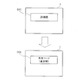
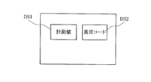
- a display method of the abnormal code for example, as shown in FIG. 17, a display method of providing an abnormal code display unit DS2 separately from the measurement value display unit DS1 and displaying the abnormal code on the display unit DS2 (For example, see Document 1 (Japanese Patent Laid-Open No. 2000-248967)).
- an abnormal code display part DS2 must be provided separately from the measurement value display part DS1, which is expensive.
- the measurement value is continuously displayed on the display unit DS1 regardless of the type of the detected abnormality.
- abnormality that affects the reliability of the measured value
- second type an abnormality that does not affect the reliability of the measured value
- first type of abnormality an abnormality that affects the reliability of the measured value
- second type an abnormality that does not affect the reliability of the measured value
- a serious failure there is no point in displaying the measured value any more, and on the contrary, displaying the unreliable measured value causes an adverse effect such as giving the monitor an erroneous recognition.
- the present invention has been made in order to solve such problems.
- the object of the present invention is to provide a low-cost configuration with a single display unit for measurement values and information indicating the contents of abnormalities.
- An object of the present invention is to provide a measuring instrument that can continue to monitor measurement values when they occur.
- the present invention affects a sensor that detects a predetermined physical quantity, a calculation unit that calculates a measured value based on the physical quantity detected by the sensor, and the reliability of the measured value.
- Abnormality detection means for detecting the first type of abnormality and the second type of abnormality that does not affect the reliability of the measurement value, the measurement value, the information indicating the content of the first type of abnormality, and the content of the second type of abnormality
- the abnormality detected by the abnormality detection means is a first type abnormality
- the information indicating the content of the first type abnormality is replaced with a measurement value.
- the display unit is controlled so as to be displayed, when the abnormality detected by the abnormality detecting means is the second type abnormality, the information indicating the content of the second type abnormality is displayed together with the measurement value.
- Display control hand to control the part It is provided with a door.
- this abnormality when a first type of abnormality (hereinafter, this abnormality is also referred to as a major failure for the sake of convenience in the present invention) occurs, information indicating the content of the major failure is replaced with a measured value, Displayed on the display.
- a second type of abnormality hereinafter, this abnormality is also referred to as a minor fault for the sake of convenience in the present invention
- information indicating the content of the minor fault is displayed on the only display unit together with the measurement value.
- a major failure (the first type of abnormality) occurs
- information indicating the content of the major failure is displayed on the only display unit instead of the measured value
- a minor failure (the second type of abnormality) is displayed.
- the information indicating the content of the minor failure is displayed on the only display part together with the measurement value, so the display unit of the measurement value and the information indicating the content of the abnormality is a single, inexpensive configuration, Monitoring of measured values when a minor failure occurs can be continued.
- FIG. 1 is a diagram for explaining a display example 1 of an abnormal code in a measuring instrument according to the present invention (a diagram showing a case where no abnormality has occurred).
- FIG. 2 is a diagram for explaining a display example 1 of an abnormal code in the measuring instrument according to the present invention (a diagram showing a case where a serious failure (first type of abnormality) has occurred).
- FIG. 3 is a diagram for explaining a display example 1 of an abnormal code in the measuring instrument according to the present invention (a diagram showing a case where a minor failure (second type abnormality) occurs).
- FIG. 4 is a diagram for explaining an example in which information indicating the content of a minor failure is displayed by providing an extra display digit of a measurement value.
- FIG. 5 is a diagram for explaining a display example (display example 2 (when multiple types of serious faults are detected)) of a fault code when a plurality of types of faults are detected.
- FIG. 6 is a diagram for explaining a display example (display example 2 (first example when multiple types of minor faults are detected)) of a fault code when a plurality of types of faults are detected.
- FIG. 7 is a diagram for explaining a display example of an abnormal code when a plurality of types of abnormalities are detected (display example 2 (second example when multiple types of minor faults are detected)).
- FIG. 8 is a diagram for explaining a display example of an abnormality code when a plurality of types of abnormality are detected (display example 2 (third example when a plurality of types of minor faults are detected)).
- FIG. 9 is a diagram for explaining a display example (display example 2 (fourth example when multiple types of minor faults are detected)) of a fault code when a plurality of types of faults are detected.
- FIG. 10 is a diagram illustrating a display example (display example 3) of an abnormal code when a major failure and a minor failure are mixedly detected.
- FIG. 11 is a diagram showing an outline of the hardware configuration of the differential pressure transmitter.
- FIG. 12 is a diagram showing a display pattern in the liquid crystal display unit of the differential pressure transmitter.
- FIG. 13 is a diagram showing a diagnostic item of a major fault executed by the diagnostic program and an abnormal code output when the major fault is detected.
- FIG. 14 is a diagram illustrating a diagnosis item of a minor fault executed by the diagnostic program and an abnormal code output when the minor fault is detected.
- FIG. 15 is a flowchart showing a characteristic processing operation executed by the CPU of the differential pressure transmitter.
- FIG. 16 is a functional block diagram of the main part of the differential pressure transmitter.
- FIG. 17 is a diagram for explaining a conventional method of displaying an abnormal code.
- FIG. 18 is a diagram for explaining an abnormal code display method that is generally considered when only the measurement value display unit is provided.
- FIG. 1 shows a case where no abnormality has occurred
- FIG. 2 shows a case where an abnormality (major failure (the first type of abnormality)) that affects the reliability of the measurement value has occurred
- FIG. This shows a case where an abnormality that does not affect the reliability (a minor failure (second type abnormality)) occurs.
- the measuring device is the differential pressure transmitter 1, and only the measured value display section DS1 is provided in the differential pressure transmitter 1 (see FIG. 1).
- the differential pressure transmitter 1 has a diagnostic function for detecting various abnormalities, and detects a major failure and a minor failure by this diagnostic function.
- the differential pressure transmitter 1 stops displaying the measured value on the display unit DS1, and displays an abnormal code indicating the content of the major fault on the display unit DS1 instead of the measured value. (See FIG. 2). While the major fault is detected, the differential pressure transmitter 1 continuously displays an abnormal code indicating the content of the major fault.
- the differential pressure transmitter 1 alternately switches and displays an abnormal code indicating the content of the minor fault and a measured value on the display unit DS1 (see FIG. 3). While the minor fault is detected, the differential pressure transmitter 1 repeats the alternate display of the abnormality code indicating the content of the minor fault and the measured value.
- the display unit of the measurement value and information indicating the content of the abnormality is configured as one, and monitoring of the measurement value is continued even if a minor failure occurs. Will be able to.
- an abnormal code indicating the content of the minor failure and a measured value are alternately switched and displayed on the display unit DS1, but as shown in FIG.
- an extra display digit of the measurement value in the display unit DS1 is provided, that is, an extra digit 1b is provided in addition to the display digit 1a of the measurement value, and information indicating the content of the minor failure is provided in the extra digit 1b. You may make it display.
- the letters “AL” indicating that there is a minor failure are displayed in the extra digits 1b of the abnormal codes indicating the contents of minor failures.
- the characters “AL” indicating this minor failure are also included in the definition of information indicating the content of the second type of abnormality (minor failure) in the present invention.
- Display Example 2 When multiple types of abnormalities are detected, the individual types of major faults and minor faults are not described, but there are various types of major faults and minor faults. That is, a plurality of types of major faults may be detected, and a plurality of types of minor faults may be detected.
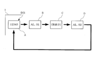
- FIG. 5 is a diagram for explaining a display example of an abnormal code on the display unit DS1 when a plurality of types of serious faults are detected.
- the differential pressure transmitter 1 displays the measured value on the display unit DS1 (A).
- A the display unit DS1
- the differential pressure transmitter 1 stops displaying the measured value on the display unit DS1, and displays an abnormal code “Err.01” indicating the content of the serious failure 1 on the display unit DS1 instead of the measured value. (B). Then, after the predetermined time has elapsed, the display unit DS1 is not displayed for a predetermined time (C). Then, after this non-display period, an abnormal code “Err.02” indicating the content of the serious failure 2 is displayed on the display unit DS1 (D).
- the display unit DS1 is not displayed for a predetermined time (E), and then the display returns to the display of the abnormal code “Err.01” indicating the content of the serious failure 1 (B). Thereafter, the same operation is repeated.
- the abnormal code “Err.01” indicating the content of the serious failure 1 and the abnormal code “Err.02” indicating the content of the serious failure 2 are alternately displayed in the non-display period. It will be displayed in a flash.
- an abnormal code indicating the content of serious failure 1 is displayed, for example, “Err.06”
- an abnormal code indicating the content of serious failure 2 is displayed, for example, “Err.08”.
- switching an abnormal code by providing a non-display period, it is possible to clearly notify that there is a change in the abnormal code, and it is possible to eliminate the possibility of overlooking the change in the code. It becomes.
- FIG. 6 is a diagram for explaining a display example (first example) of an abnormal code on the display unit DS1 when a plurality of types of minor faults are detected.
- the differential pressure transmitter 1 displays the measured value on the display unit DS1 (A).
- A the display unit DS1
- the differential pressure transmitter 1 interrupts the display of the measured value on the display unit DS1, and displays the abnormal code “AL.01” indicating the content of the minor failure 1 on the display unit DS1 (B). Then, after the predetermined time has elapsed, the measured value is displayed on the display unit DS1 for a predetermined time (C). Then, after displaying the measured value, an abnormality code “AL.02” indicating the content of minor failure 2 is displayed on the display unit DS1 (D), and after a predetermined time has elapsed, the display returns to the measured value display (A). Thereafter, the same operation is repeated.
- an abnormality code “AL.01” indicating the content of minor failure 1 and an abnormality code “AL.02” indicating the content of minor failure 2 are sequentially displayed across the measurement value on the display unit DS1. It will be displayed by switching.
- an abnormal code indicating the content of minor failure 1 is displayed as, for example, “AL.06”
- an abnormal code indicating the content of minor failure 2 is displayed as, for example, “AL.08”. If so, there are few parts that change, and there is a possibility that the change of the code is missed.
- switching an abnormal code by interposing a measurement value between them, it is possible to clearly notify that there is a change in the abnormal code and eliminate the possibility of missing the code change. It becomes possible.
- the abnormal code indicating the content of the detected minor failure is sequentially displayed on the display unit DS1 with the measurement value interposed therebetween.
- FIG. 7 is a diagram for explaining another display example (second example) of an abnormal code on the display unit DS1 when a plurality of types of minor faults are detected.
- the differential pressure transmitter 1 displays the measured value on the display unit DS1 (A).
- A the display unit DS1
- the differential pressure transmitter 1 interrupts the display of the measured value on the display unit DS1, and displays the abnormal code “AL.01” indicating the content of the minor failure 1 on the display unit DS1 (B). Then, after the predetermined time has elapsed, the display unit DS1 is not displayed for a predetermined time (C). Then, after this non-display period, an abnormal code “AL.02” indicating the content of minor failure 2 is displayed on the display unit DS1 (D), and after a predetermined time has elapsed, the display returns to the measurement value display (A). Thereafter, the same operation is repeated.
- a group of abnormal codes indicating the measurement value and the content of the minor fault are alternately displayed on the display unit DS1, and the group of the minor fault indicating the content of the minor fault is displayed.
- the abnormal code “AL.01” indicating the content and the abnormal code “AL.02” indicating the content of minor failure 2 are displayed with the non-display time interposed therebetween.
- an abnormality indicating the content of the minor failure 1 with a display value change period having a large change in display contents and a non-display period having a change change in display contents can be clearly distinguished and notified.
- the display unit DS1 a group of abnormality codes indicating the measured values and the contents of minor faults are alternately displayed. In the group of abnormal codes indicating the contents of minor faults, no abnormality codes indicating the contents of minor faults are displayed. The images are sequentially switched over a period.
- Display example 3 When a major failure and a minor failure are mixed]
- the display example when only a major failure is detected and the display example when only a minor failure is detected have been described.
- Major and minor failures actually occur in a mixed manner. If a major failure occurs, the measured value is not reliable, no matter how minor the failure is.
- the abnormal codes indicating the contents of the minor faults are displayed as shown in FIGS.
- an abnormal code indicating the content of the major failure and an abnormal code indicating the content of the minor failure are displayed on the display unit DS1 with a non-display period interposed therebetween.
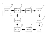
- FIG. 10 is a diagram for explaining a display example of an abnormality code when a major failure and a minor failure are detected together.
- the differential pressure transmitter 1 measures on the display unit DS1.
- the value is displayed (A).
- two types of major faults ie, major fault 1 and major fault 2
- two types of minor faults minor fault 1 and minor fault 2
- the differential pressure transmitter 1 stops displaying the measured value on the display unit DS1, and displays an abnormal code “Err.01” indicating the content of the serious failure 1 on the display unit DS1 instead of the measured value.
- the display unit DS1 is not displayed for a predetermined time (C).
- an abnormal code “Err.02” indicating the content of the serious failure 2 is displayed on the display unit DS1 (D), and the display unit DS1 is not displayed for a predetermined time after the predetermined time has elapsed.
- E E.
- the differential pressure transmitter 1 displays an abnormal code “AL.01” indicating the content of the minor failure 1 on the display unit DS1 (F), and after the predetermined time has elapsed, the display unit DS1 is not displayed for a predetermined time.
- Display (G) After this non-display period, an abnormal code “AL.02” indicating the content of minor failure 2 is displayed on the display unit DS1 (H), and the display unit DS1 is not displayed for a predetermined time after a predetermined time has elapsed. After that, the display returns to the display of the abnormal code “Err.01” indicating the content of the serious failure 1 (B). Thereafter, the same operation is repeated.
- the display unit DS1 displays an abnormal code “Err.01” indicating the contents of the major fault 1, an abnormal code “Err.02” indicating the contents of the major fault 2, and the contents of the minor fault 1. And an abnormal code “AL.02” indicating the content of minor failure 2 are sequentially displayed with a non-display period.
- the change in the display content is large with a non-display period in between, and the abnormal code indicating the content of the major failure 1 and the abnormal code indicating the content of the major failure 2 are clearly distinguished, and the minor failure
- the abnormal code indicating the content of 1 and the abnormal code indicating the content of minor failure 2 can be clearly distinguished and notified.
- a group of error codes of a major failure is displayed first, and then a group of error codes of a minor failure are displayed.
- a group of abnormal codes of major faults may be displayed, or an abnormal code of major faults and an abnormal code of minor faults may be displayed separately.
- the display unit DS1 does not display the abnormal code indicating the content of the detected major fault and the abnormal code indicating the minor fault in the same manner.
- the images are sequentially switched over a period.
- FIG. 11 shows an outline of the hardware configuration of the differential pressure transmitter 1.
- 1-1 is a CPU
- 1-2 is a RAM
- 1-3 is a ROM
- 1-4 is an NVM (nonvolatile memory)
- 1-5 is a liquid crystal display
- S1 is a differential pressure sensor
- S2 is a static sensor
- a pressure sensor, S3 is a temperature sensor
- 1-6 to 1-8 are A / D converters.
- the differential pressure transmitter 1 includes a differential pressure sensor S1, a static pressure sensor S2, and a temperature sensor S3 as its constituent elements.
- the CPU 1-1 receives a signal indicating a differential pressure from the differential pressure sensor S1 input via the A / D converter 1-6, and a static pressure sensor S2 input via the A / D converter 1-7.
- the program stored in the ROM 1-3 while obtaining the signal indicating the static pressure of the liquid and the signal indicating the temperature input via the A / D converter 1-8 and accessing the RAM 1-2 and NVM 1-4 operates according to.
- ROM 1-3 as a program unique to the present embodiment, various arithmetic processes are performed on a signal indicating the differential pressure from the differential pressure sensor S1, and a measured value of the differential pressure is obtained and displayed on the liquid crystal display unit 1-5.
- a measured value display program, a diagnostic program for detecting various abnormalities determined in advance, and an abnormal code display program for displaying an abnormal code on the liquid crystal display unit 1-5 based on a diagnostic result according to the diagnostic program are stored. Yes.
- FIG. 12 shows a display pattern in the liquid crystal display unit 1-5.
- AR1 is a display area for measurement values
- AR2 is a display area for various auxiliary information
- AR3 is a display area for displaying measurement values in a bar graph
- the display area AR1 is composed of 7 segment groups as main components.
- the display area AR2 has a 16-segment group as a main component.
- the display area AR1 corresponds to the display unit DS1 in the display example 3.
- FIG. 13 shows the diagnosis items of the major fault executed by the diagnostic program and the abnormal code output when the major fault is detected.
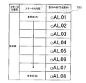
- FIG. 14 shows a diagnosis item of a minor fault executed by the diagnostic program and an abnormal code output when the minor fault is detected. 13 and 14 show the diagnosis items from the top in descending order of importance.
- a table TB1 having contents as shown in FIG. 13 and TB2 having contents as shown in FIG. 14 are stored in the ROM 1-3.
- CPU 1-1 executes a diagnostic program and checks normality / abnormality for all diagnostic items (step S101). Here, if there is neither a major failure nor a minor failure and everything is normal (“normal” in step S101), the measurement value obtained by the measurement value display program is displayed on the liquid crystal display unit 1-5 (step S102).
- step S101 if a major failure or minor failure has occurred and it is determined that there is an abnormality (“abnormal” in step S101), it is checked whether the abnormality includes a major failure (step S103). If no major faults are included and all are minor faults (NO in step S103), for example, as shown in FIG. 6, an abnormal code indicating the content of the minor fault is sandwiched between the measured values.
- the display area AR1 (DS1) of the liquid crystal display unit 1-5 is sequentially switched and displayed (step S104). In this case, according to the table TB2 shown in FIG. 14, the abnormal codes indicating the contents of the minor faults are sequentially displayed in descending order of importance.
- step S103 If even one major fault is included (YES in step S103), for example, as shown in FIG. 10, display of the measured value is stopped, and an abnormal code indicating the contents of the major fault and the contents of the minor fault are displayed.
- the abnormal code shown is sequentially switched and displayed in the display area AR1 (DS) of the liquid crystal display unit 1-5 with a non-display period (step S105).
- the abnormality code indicating the content of the major failure is in accordance with the table TB1 shown in FIG. 13, and the abnormality code indicating the content of the minor failure is in accordance with the table TB2 shown in FIG. Display in order from the highest.
- the display area AR1 of the measured value in the liquid crystal display unit 1-5 is the 7 segment group, but it may be a 16 segment group.
- 7 segments it is possible to display several alphabet characters in addition to 10 types of numbers, but the number is limited. With 16 segments, the types of characters to be displayed can be further increased.
- the segment method is not necessarily used, and a dot matrix type LCD or the like may be used.
- a segment system such as a 7-segment group or a 16-segment group is used, the power consumption can be reduced and the configuration is also inexpensive.
- the display unit 1-5 is a liquid crystal display unit.
- a display unit using a light emitting diode (LED), a cold cathode discharge lamp, a fluorescent display tube, an incandescent filament, or the like may be used.
- the display may be blinked immediately after the display is switched. For example, when the display period of one abnormal code is 3 seconds, the blinking of 0.25 seconds is performed for 1 second immediately after the display is switched, and the remaining 2 seconds are lit. For example, when a dot matrix liquid crystal is used, the display is inverted every time the display is switched. When a color liquid crystal is used, the color is changed every time the display is switched. In the case of these methods, it is not necessary to provide a non-display period at the time of switching, but visibility may be further improved in combination with the non-display period.
- the information indicating the content of the abnormality of the major failure or the light failure does not necessarily have to be an abnormality code, and a message that specifically represents the content of the abnormality in characters. It is good also as a pictogram which shows the content of abnormality.
- FIG. 16 shows a functional block diagram of the main part of the differential pressure transmitter 1 according to the first embodiment.
- the differential pressure transmitter 1 includes a calculation unit 1A that obtains a measured value of the differential pressure, a display unit 1B, an abnormality detection unit 1C, and a display control unit 1D.
- the calculation unit 1A receives a signal indicating the differential pressure from the differential pressure sensor S1, and performs a predetermined calculation process to obtain a measured value of the differential pressure.
- the measured value of the differential pressure from the calculation unit 1A is displayed on the display unit 1B.
- the abnormality detection unit 1C receives various signals such as a signal indicating the differential pressure from the differential pressure sensor S1, a signal indicating the static pressure from the static pressure sensor S2, and a signal indicating the temperature from the temperature sensor S3. Is detected.
- the display control unit 1D Based on the abnormality detected by the abnormality detection unit 1C, the display control unit 1D replaces the measured value with an abnormality code indicating the content of the serious failure when one of the abnormalities is included.
- An abnormal code indicating the content of the minor fault is displayed on the display unit 1B with the non-display period being sequentially switched. If all of the abnormalities are minor faults, the abnormal code indicating the minor fault is measured. The value is displayed on the display unit 1B together with the value.
- the calculation unit 1A, abnormality detection unit 1C, and display control unit 1D are realized as processing functions of the CPU 1-1.
- the calculation unit 1A converts the differential pressure detected by the differential pressure sensor S1 into a measurement value and outputs the measurement value to the display unit 1B. Such conversion from the differential pressure to the measurement value in the calculation unit 1A is also included in the calculation by the calculation means in the present invention.
- the measuring device of the present invention is not limited to the differential pressure transmitter, and can be applied to, for example, an odometer or a trip meter provided in an automobile or the like.
Abstract
Description
〔表示例1〕
図1~図3はこの発明に係る計測機器における異常コードの表示例1を説明する図である。図1は異常が発生していない場合を示し、図2は計測値の信頼性に影響を与える異常(重故障(第1種の異常))が発生した場合を示し、図3は計測値の信頼性に影響を与えない異常(軽故障(第2種の異常))が発生した場合を示している。 Hereinafter, the present invention will be described in detail with reference to the drawings.
[Display example 1]
1 to 3 are diagrams for explaining a display example 1 of an abnormal code in the measuring instrument according to the present invention. FIG. 1 shows a case where no abnormality has occurred, FIG. 2 shows a case where an abnormality (major failure (the first type of abnormality)) that affects the reliability of the measurement value has occurred, and FIG. This shows a case where an abnormality that does not affect the reliability (a minor failure (second type abnormality)) occurs.
差圧発信器1は、重故障が検出された場合、表示部DS1での計測値の表示を中止し、この計測値に代えて、表示部DS1にその重故障の内容を示す異常コードを表示する(図2参照)。差圧発信器1は、重故障が検出されている間、この重故障の内容を示す異常コードの表示を継続して行う。 [Display example when a serious failure is detected]
When a major fault is detected, the
差圧発信器1は、軽故障が検出された場合、その軽故障の内容を示す異常コードと計測値とを表示部DS1に交互に切り替えて表示する(図3参照)。差圧発信器1は、軽故障が検出されている間、その軽故障の内容を示す異常コードと計測値との交互表示を繰り返す。 [Display example when a minor failure is detected]
When a minor fault is detected, the
表示例1では、重故障や軽故障の個々の種別については述べなかったが、重故障や軽故障には色々な種別がある。すなわち、複数種類の重故障が検出されることもあり、複数種類の軽故障が検出されることもある。 [Display Example 2: When multiple types of abnormalities are detected]
In display example 1, the individual types of major faults and minor faults are not described, but there are various types of major faults and minor faults. That is, a plurality of types of major faults may be detected, and a plurality of types of minor faults may be detected.
図5は重故障が複数種類検出された場合の表示部DS1における異常コードの表示例を説明する図である。異常が発生していない場合、差圧発信器1は、表示部DS1に計測値を表示している(A)。ここで、重故障として、重故障1と重故障2の2種類が検出されたとする。 [Display example when multiple types of serious faults are detected]
FIG. 5 is a diagram for explaining a display example of an abnormal code on the display unit DS1 when a plurality of types of serious faults are detected. When no abnormality has occurred, the
図6は軽故障が複数種類検出された場合の表示部DS1における異常コードの表示例(第1例)を説明する図である。異常が発生していない場合、差圧発信器1は、表示部DS1に計測値を表示している(A)。ここで、軽故障として、軽故障1と軽故障2の2種類が検出されたとする。 [Display example when multiple types of minor faults are detected (first example)]
FIG. 6 is a diagram for explaining a display example (first example) of an abnormal code on the display unit DS1 when a plurality of types of minor faults are detected. When no abnormality has occurred, the
図7は軽故障が複数種類検出された場合の表示部DS1における異常コードの別の表示例(第2例)を説明する図である。異常が発生していない場合、差圧発信器1は、表示部DS1に計測値を表示している(A)。ここで、軽故障として、軽故障1と軽故障2の2種類が検出されたとする。 [Display example when multiple types of minor faults are detected (second example)]
FIG. 7 is a diagram for explaining another display example (second example) of an abnormal code on the display unit DS1 when a plurality of types of minor faults are detected. When no abnormality has occurred, the
図6に示した例では、計測値の表示期間と軽故障の内容を示す異常コードの表示期間との間に無表示期間を設けなかったが、図8に示すように、その間に無表示期間を設けるようにしてもよい。 [Display example when multiple types of minor faults are detected (third example)]
In the example shown in FIG. 6, no display period is provided between the display period of the measured value and the display period of the abnormal code indicating the content of the minor failure. However, as shown in FIG. May be provided.
図7に示した例では、計測値の表示期間と軽故障の内容を示す異常コードの表示期間との間に無表示期間を設けなかったが、図9に示すように、その間に無表示期間を設けるようにしてもよい。 [Display example when multiple types of minor faults are detected (fourth example)]
In the example shown in FIG. 7, no non-display period is provided between the display period of the measured value and the display period of the abnormal code indicating the content of the minor failure. However, as shown in FIG. May be provided.
表示例1,2では、重故障のみが検出された場合の表示例、軽故障のみが検出された場合の表示例について、説明した。重故障や軽故障は、実際には、入り混じって発生する。重故障が生じている場合には、いくら軽故障があったからといって、計測値に信頼性はない。 [Display example 3: When a major failure and a minor failure are mixed]
In the display examples 1 and 2, the display example when only a major failure is detected and the display example when only a minor failure is detected have been described. Major and minor failures actually occur in a mixed manner. If a major failure occurs, the measured value is not reliable, no matter how minor the failure is.
次に、上述した表示例3を例にとって、差圧発信器1における処理動作の具体例について説明する。図11に差圧発信器1のハードウェア構成の概略を示す。同図において、1-1はCPU、1-2はRAM、1-3はROM、1-4はNVM(不揮発性メモリ)、1-5は液晶表示部、S1は差圧センサ、S2は静圧センサ、S3は温度センサ、1-6~1-8はA/D変換器である。差圧発信器1は、差圧センサS1、静圧センサS2,温度センサS3についても、その構成要素として含む。 [Example 1]
Next, a specific example of the processing operation in the
例えば、1つの異常コードの表示期間を3秒としたとき、表示切り替わり直後の1秒間は0.25秒間の点滅とし、残りの2秒間は点灯させたりする。
例えば、ドットマトリクス液晶を使用する場合は、表示切替毎に反転表示させたり、カラー液晶を使用する場合は、表示切替毎に色を変えたりする。
これらの方式の場合は、切り替わり時に無表示期間を設けることは不要となるが、無表示期間と組み合わせて、より視認性を高めてもよい。 Further, in the display examples 1 to 3 and the first embodiment described above, instead of providing a non-display period, the display may be blinked immediately after the display is switched.
For example, when the display period of one abnormal code is 3 seconds, the blinking of 0.25 seconds is performed for 1 second immediately after the display is switched, and the remaining 2 seconds are lit.
For example, when a dot matrix liquid crystal is used, the display is inverted every time the display is switched. When a color liquid crystal is used, the color is changed every time the display is switched.
In the case of these methods, it is not necessary to provide a non-display period at the time of switching, but visibility may be further improved in combination with the non-display period.
Claims (7)
- 所定の物理量を検出するセンサと、
このセンサによって検出された物理量に基づいて計測値を演算する演算手段と、
前記計測値の信頼性に影響を与える第1種の異常および前記計測値の信頼性に影響を与えない第2種の異常を検出する異常検出手段と、
前記計測値、前記第1種の異常の内容を示す情報および前記第2種の異常の内容を示す情報の少なくとも1つを表示する表示部と、
前記異常検出手段によって検出された異常が前記第1種の異常であった場合、その第1種の異常の内容を示す情報を前記計測値に代えて表示させるように前記表示部を制御する一方、前記異常検出手段によって検出された異常が前記第2種の異常であった場合、その第2種の異常の内容を示す情報を前記計測値とともに表示させるように前記表示部を制御する表示制御手段と
を備えることを特徴とする計測機器。 A sensor for detecting a predetermined physical quantity;
A calculation means for calculating a measurement value based on the physical quantity detected by the sensor;
An abnormality detecting means for detecting a first type of abnormality that affects the reliability of the measurement value and a second type of abnormality that does not affect the reliability of the measurement value;
A display unit that displays at least one of the measurement value, information indicating the content of the first type of abnormality, and information indicating the content of the second type of abnormality;
When the abnormality detected by the abnormality detection means is the first type abnormality, the display unit is controlled to display information indicating the content of the first type abnormality instead of the measurement value. When the abnormality detected by the abnormality detection means is the second type abnormality, the display control is performed to control the display unit so that the information indicating the content of the second type abnormality is displayed together with the measurement value. A measuring instrument comprising: means. - 請求項1に記載された計測機器において、
前記表示制御手段は、
前記異常検出手段によって検出された異常が前記第2種の異常であった場合、その検出された第2の異常の内容を示す情報と前記計測値とを前記表示部に交互に切り替えて表示させる
ことを特徴とする計測機器。 The measuring instrument according to claim 1,
The display control means includes
When the abnormality detected by the abnormality detection means is the second type abnormality, information indicating the content of the detected second abnormality and the measurement value are alternately switched and displayed on the display unit. Measuring equipment characterized by that. - 請求項1に記載された計測機器において、
前記表示制御手段は、
前記異常検出手段によって検出された異常が複数種類の前記第1種の異常であった場合、前記計測値に代えて、その検出された第1種の異常の種類毎の異常の内容を示す情報を所定の無表示期間を挾んで前記表示部に順次切り替えて表示させる一方、
前記異常検出手段によって検出された異常が複数種類の前記第2種の異常であった場合、その検出された第2種の異常の種類毎の異常の内容を示す情報を前記計測値を挾んで前記表示部に順次切り替えて表示させる
ことを特徴とする計測機器。 The measuring instrument according to claim 1,
The display control means includes
When the abnormality detected by the abnormality detection means is a plurality of types of the first type of abnormality, information indicating the content of the abnormality for each type of the detected first type of abnormality instead of the measurement value While sequentially switching to the display unit for a predetermined non-display period,
When the abnormality detected by the abnormality detection means is a plurality of types of the second type of abnormality, the information indicating the content of the abnormality for each type of the detected second type of abnormality is stored in the measurement value. A measuring instrument, wherein the display unit is sequentially switched and displayed. - 請求項1に記載された計測機器において、
前記表示制御手段は、
前記異常検出手段によって検出された異常が複数種類の前記第1種の異常であった場合、前記計測値に代えて、その検出された第1種の異常の種類毎の異常の内容を示す情報を所定の無表示期間を挾んで前記表示部に順次切り替えて表示させる一方、
前記異常検出手段によって検出された異常が複数種類の前記第2種の異常であった場合、前記計測値の表示を一時中断し、その検出された第2種の異常の種類毎の異常の内容を示す情報を所定の無表示期間を挾んで前記表示部に順次切り替えて表示させる
ことを特徴とする計測機器。 The measuring instrument according to claim 1,
The display control means includes
When the abnormality detected by the abnormality detection means is a plurality of types of the first type of abnormality, information indicating the content of the abnormality for each type of the detected first type of abnormality instead of the measurement value While sequentially switching to the display unit for a predetermined non-display period,
If the abnormality detected by the abnormality detection means is a plurality of types of the second type of abnormality, the display of the measurement value is temporarily suspended, and the contents of the abnormality for each type of the detected second type of abnormality The measuring device is characterized by sequentially switching and displaying information on the display unit with a predetermined non-display period. - 請求項1に記載された計測機器において、
前記表示制御手段は、
前記異常検出手段によって検出された異常が全て前記第2種の異常であった場合にのみ、その第2種の異常の内容を示す情報を前記計測値とともに前記表示部に表示させる
ことを特徴とする計測機器。 The measuring instrument according to claim 1,
The display control means includes
Only when all the abnormalities detected by the abnormality detecting means are the second type abnormality, information indicating the content of the second type abnormality is displayed on the display unit together with the measurement value. Measuring instrument to be used. - 請求項5に記載された計測機器において、
前記表示制御手段は、
前記異常検出手段によって検出された異常に前記第1種の異常と前記第2種の異常が含まれていた場合、前記計測値に代えて、その第1種の異常の内容を示す情報と第2の異常の内容を示す情報を所定の無表示期間を挟んで前記表示部に順次切り替えて表示させる
ことを特徴とする計測機器。 In the measuring instrument according to claim 5,
The display control means includes
If the abnormality detected by the abnormality detection means includes the first type abnormality and the second type abnormality, information indicating the content of the first type abnormality and the first type instead of the measurement value Information indicating the content of the abnormality of 2 is sequentially switched and displayed on the display unit with a predetermined non-display period in between. - 請求項1に記載された計測機器において、
前記表示部は、セグメント群によって構成されている
ことを特徴とする計測機器。 The measuring instrument according to claim 1,
The display device includes a segment group.
Priority Applications (4)
| Application Number | Priority Date | Filing Date | Title |
|---|---|---|---|
| EP08866386.9A EP2226614A4 (en) | 2007-12-28 | 2008-12-01 | Measuring apparatus |
| CN200880122653XA CN101910800B (en) | 2007-12-28 | 2008-12-01 | Measuring apparatus |
| US12/810,629 US8248264B2 (en) | 2007-12-28 | 2008-12-01 | Measuring apparatus |
| KR1020107013915A KR101156281B1 (en) | 2007-12-28 | 2008-12-01 | Measuring apparatus |
Applications Claiming Priority (2)
| Application Number | Priority Date | Filing Date | Title |
|---|---|---|---|
| JP2007339658A JP4984294B2 (en) | 2007-12-28 | 2007-12-28 | Measuring equipment |
| JP2007-339658 | 2007-12-28 |
Publications (1)
| Publication Number | Publication Date |
|---|---|
| WO2009084357A1 true WO2009084357A1 (en) | 2009-07-09 |
Family
ID=40824079
Family Applications (1)
| Application Number | Title | Priority Date | Filing Date |
|---|---|---|---|
| PCT/JP2008/071787 WO2009084357A1 (en) | 2007-12-28 | 2008-12-01 | Measuring apparatus |
Country Status (6)
| Country | Link |
|---|---|
| US (1) | US8248264B2 (en) |
| EP (1) | EP2226614A4 (en) |
| JP (1) | JP4984294B2 (en) |
| KR (1) | KR101156281B1 (en) |
| CN (1) | CN101910800B (en) |
| WO (1) | WO2009084357A1 (en) |
Cited By (1)
| Publication number | Priority date | Publication date | Assignee | Title |
|---|---|---|---|---|
| WO2019026245A1 (en) * | 2017-08-03 | 2019-02-07 | 三菱電機株式会社 | Monitoring control screen display device |
Families Citing this family (3)
| Publication number | Priority date | Publication date | Assignee | Title |
|---|---|---|---|---|
| JP6059046B2 (en) * | 2013-03-04 | 2017-01-11 | アズビル株式会社 | Defect detection system and defect detection method |
| DE102015102486B4 (en) * | 2015-02-20 | 2021-01-28 | Krohne Messtechnik Gmbh | Field device for determining a measured variable and method for communication |
| CN107015041B (en) * | 2017-04-10 | 2019-04-26 | 四川长虹电器股份有限公司 | The method of malfunction coefficient processing |
Citations (7)
| Publication number | Priority date | Publication date | Assignee | Title |
|---|---|---|---|---|
| JPS5585997A (en) * | 1978-12-22 | 1980-06-28 | Tokyo Shibaura Electric Co | Display unit |
| JPS60246414A (en) * | 1984-05-22 | 1985-12-06 | Matsui Seisakusho:Kk | Temperature automatic control device of thermal medium |
| JPH01263793A (en) * | 1988-04-14 | 1989-10-20 | Toshiba Corp | Process display device |
| JPH02128115A (en) * | 1988-11-08 | 1990-05-16 | Toshiba Corp | Digital display device |
| JPH04315296A (en) * | 1991-04-12 | 1992-11-06 | Komatsu Ltd | Fault diagnosis display device |
| JP2000248967A (en) | 1999-02-25 | 2000-09-12 | Hitachi Ltd | Solenoid-operated valve system drive intake or exhaust valve of internal combustion engine and control method thereof |
| JP2002248967A (en) * | 2001-02-21 | 2002-09-03 | Fuji Heavy Ind Ltd | Vehicle trouble diagnosis display device |
Family Cites Families (3)
| Publication number | Priority date | Publication date | Assignee | Title |
|---|---|---|---|---|
| US5631629A (en) * | 1995-02-08 | 1997-05-20 | Allen-Bradley Company, Inc. | Heartbeat communications |
| JP4082306B2 (en) * | 2003-08-08 | 2008-04-30 | 三菱ふそうトラック・バス株式会社 | Fault diagnosis device |
| US7183905B2 (en) * | 2003-09-05 | 2007-02-27 | Siemens Power Generation, Inc. | Tool for sensor management and fault visualization in machine condition monitoring |
-
2007
- 2007-12-28 JP JP2007339658A patent/JP4984294B2/en active Active
-
2008
- 2008-12-01 WO PCT/JP2008/071787 patent/WO2009084357A1/en active Application Filing
- 2008-12-01 EP EP08866386.9A patent/EP2226614A4/en not_active Withdrawn
- 2008-12-01 US US12/810,629 patent/US8248264B2/en active Active
- 2008-12-01 KR KR1020107013915A patent/KR101156281B1/en active IP Right Grant
- 2008-12-01 CN CN200880122653XA patent/CN101910800B/en active Active
Patent Citations (7)
| Publication number | Priority date | Publication date | Assignee | Title |
|---|---|---|---|---|
| JPS5585997A (en) * | 1978-12-22 | 1980-06-28 | Tokyo Shibaura Electric Co | Display unit |
| JPS60246414A (en) * | 1984-05-22 | 1985-12-06 | Matsui Seisakusho:Kk | Temperature automatic control device of thermal medium |
| JPH01263793A (en) * | 1988-04-14 | 1989-10-20 | Toshiba Corp | Process display device |
| JPH02128115A (en) * | 1988-11-08 | 1990-05-16 | Toshiba Corp | Digital display device |
| JPH04315296A (en) * | 1991-04-12 | 1992-11-06 | Komatsu Ltd | Fault diagnosis display device |
| JP2000248967A (en) | 1999-02-25 | 2000-09-12 | Hitachi Ltd | Solenoid-operated valve system drive intake or exhaust valve of internal combustion engine and control method thereof |
| JP2002248967A (en) * | 2001-02-21 | 2002-09-03 | Fuji Heavy Ind Ltd | Vehicle trouble diagnosis display device |
Non-Patent Citations (1)
| Title |
|---|
| See also references of EP2226614A4 * |
Cited By (1)
| Publication number | Priority date | Publication date | Assignee | Title |
|---|---|---|---|---|
| WO2019026245A1 (en) * | 2017-08-03 | 2019-02-07 | 三菱電機株式会社 | Monitoring control screen display device |
Also Published As
| Publication number | Publication date |
|---|---|
| JP2009162520A (en) | 2009-07-23 |
| JP4984294B2 (en) | 2012-07-25 |
| CN101910800B (en) | 2012-06-13 |
| KR101156281B1 (en) | 2012-06-13 |
| US20100265085A1 (en) | 2010-10-21 |
| EP2226614A1 (en) | 2010-09-08 |
| CN101910800A (en) | 2010-12-08 |
| US8248264B2 (en) | 2012-08-21 |
| KR20100090291A (en) | 2010-08-13 |
| EP2226614A4 (en) | 2013-12-18 |
Similar Documents
| Publication | Publication Date | Title |
|---|---|---|
| CN109891313B (en) | Liquid crystal display device and failure inspection method | |
| WO2009084357A1 (en) | Measuring apparatus | |
| US4247852A (en) | Monitoring system for indicators utilizing individually energizable segments | |
| WO2006003919A1 (en) | Liquid crystal display and analyzer provided with the same | |
| US7839277B2 (en) | Monitoring system and temperature controller | |
| JP2007128440A (en) | Operation management device for water treatment plant | |
| US20090222699A1 (en) | Method for Displaying Quality of a Digital Communications Link for Field Devices of Automation Technology | |
| JP2002229642A (en) | Operation control system for production line and production equipment | |
| JP5818758B2 (en) | PLC system | |
| JP2012083608A (en) | Display mechanism monitoring device | |
| JP2005265454A (en) | Fault diagnosis device for vehicle | |
| KR100760404B1 (en) | Before diagnosis system for electric instrument and diagnosis method using the same | |
| US20210063371A1 (en) | Gas-measuring system and process for operating a gas-measuring system | |
| JP2000097095A (en) | Self-diagnosis display device | |
| KR20120004264U (en) | Switch fault location detection method and indicator method system | |
| JPH06250605A (en) | Led display device and led display machine | |
| JP5061944B2 (en) | Error content code display method | |
| JP2005098901A (en) | Tft array inspection device | |
| JPS60125730A (en) | Apparatus for displaying abnormal operation of engine | |
| JP4066198B2 (en) | Safety-specific input device | |
| JPH02213719A (en) | Sensor state display device | |
| JP2012127662A (en) | Flow rate measuring device | |
| JP2635797B2 (en) | Process quantity display | |
| KR930003794Y1 (en) | Checking apparatus for mechanical troubles | |
| JPH077340B2 (en) | System unit |
Legal Events
| Date | Code | Title | Description |
|---|---|---|---|
| WWE | Wipo information: entry into national phase |
Ref document number: 200880122653.X Country of ref document: CN |
|
| 121 | Ep: the epo has been informed by wipo that ep was designated in this application |
Ref document number: 08866386 Country of ref document: EP Kind code of ref document: A1 |
|
| ENP | Entry into the national phase |
Ref document number: 20107013915 Country of ref document: KR Kind code of ref document: A |
|
| WWE | Wipo information: entry into national phase |
Ref document number: 12810629 Country of ref document: US |
|
| NENP | Non-entry into the national phase |
Ref country code: DE |
|
| REEP | Request for entry into the european phase |
Ref document number: 2008866386 Country of ref document: EP |
|
| WWE | Wipo information: entry into national phase |
Ref document number: 2008866386 Country of ref document: EP |