WO2008110060A1 - Dispositif d'auto-séparation eau-huile et dispositif de récupération, et système les combinant - Google Patents
Dispositif d'auto-séparation eau-huile et dispositif de récupération, et système les combinant Download PDFInfo
- Publication number
- WO2008110060A1 WO2008110060A1 PCT/CN2008/000424 CN2008000424W WO2008110060A1 WO 2008110060 A1 WO2008110060 A1 WO 2008110060A1 CN 2008000424 W CN2008000424 W CN 2008000424W WO 2008110060 A1 WO2008110060 A1 WO 2008110060A1
- Authority
- WO
- WIPO (PCT)
- Prior art keywords
- water
- oil
- tank
- recovery
- separation
- Prior art date
Links
Classifications
-
- B—PERFORMING OPERATIONS; TRANSPORTING
- B01—PHYSICAL OR CHEMICAL PROCESSES OR APPARATUS IN GENERAL
- B01D—SEPARATION
- B01D17/00—Separation of liquids, not provided for elsewhere, e.g. by thermal diffusion
- B01D17/02—Separation of non-miscible liquids
- B01D17/0208—Separation of non-miscible liquids by sedimentation
-
- B—PERFORMING OPERATIONS; TRANSPORTING
- B01—PHYSICAL OR CHEMICAL PROCESSES OR APPARATUS IN GENERAL
- B01D—SEPARATION
- B01D17/00—Separation of liquids, not provided for elsewhere, e.g. by thermal diffusion
- B01D17/02—Separation of non-miscible liquids
-
- B—PERFORMING OPERATIONS; TRANSPORTING
- B01—PHYSICAL OR CHEMICAL PROCESSES OR APPARATUS IN GENERAL
- B01D—SEPARATION
- B01D17/00—Separation of liquids, not provided for elsewhere, e.g. by thermal diffusion
- B01D17/08—Thickening liquid suspensions by filtration
- B01D17/10—Thickening liquid suspensions by filtration with stationary filtering elements
-
- C—CHEMISTRY; METALLURGY
- C02—TREATMENT OF WATER, WASTE WATER, SEWAGE, OR SLUDGE
- C02F—TREATMENT OF WATER, WASTE WATER, SEWAGE, OR SLUDGE
- C02F1/00—Treatment of water, waste water, or sewage
- C02F1/001—Processes for the treatment of water whereby the filtration technique is of importance
-
- C—CHEMISTRY; METALLURGY
- C02—TREATMENT OF WATER, WASTE WATER, SEWAGE, OR SLUDGE
- C02F—TREATMENT OF WATER, WASTE WATER, SEWAGE, OR SLUDGE
- C02F1/00—Treatment of water, waste water, or sewage
- C02F1/006—Water distributors either inside a treatment tank or directing the water to several treatment tanks; Water treatment plants incorporating these distributors, with or without chemical or biological tanks
-
- C—CHEMISTRY; METALLURGY
- C02—TREATMENT OF WATER, WASTE WATER, SEWAGE, OR SLUDGE
- C02F—TREATMENT OF WATER, WASTE WATER, SEWAGE, OR SLUDGE
- C02F1/00—Treatment of water, waste water, or sewage
- C02F1/40—Devices for separating or removing fatty or oily substances or similar floating material
-
- C—CHEMISTRY; METALLURGY
- C02—TREATMENT OF WATER, WASTE WATER, SEWAGE, OR SLUDGE
- C02F—TREATMENT OF WATER, WASTE WATER, SEWAGE, OR SLUDGE
- C02F2103/00—Nature of the water, waste water, sewage or sludge to be treated
- C02F2103/008—Originating from marine vessels, ships and boats, e.g. bilge water or ballast water
-
- Y—GENERAL TAGGING OF NEW TECHNOLOGICAL DEVELOPMENTS; GENERAL TAGGING OF CROSS-SECTIONAL TECHNOLOGIES SPANNING OVER SEVERAL SECTIONS OF THE IPC; TECHNICAL SUBJECTS COVERED BY FORMER USPC CROSS-REFERENCE ART COLLECTIONS [XRACs] AND DIGESTS
- Y10—TECHNICAL SUBJECTS COVERED BY FORMER USPC
- Y10S—TECHNICAL SUBJECTS COVERED BY FORMER USPC CROSS-REFERENCE ART COLLECTIONS [XRACs] AND DIGESTS
- Y10S210/00—Liquid purification or separation
- Y10S210/05—Coalescer
Definitions
- the present invention relates to oil-water separation technology, and more particularly to an apparatus for automatically separating and recovering oil and water. Background technique
- Oil spill pollution is mainly divided into three categories: marine oil spill pollution, oil spill pollution from offshore production and land source oil spill pollution.
- Luyuan oil spill pollution mainly refers to the mainland water system, all kinds of ships in the river, river, and lake are sailing, because the inevitable bilge oily sewage in the engine room is directly discharged into the continental water body without effective degreasing treatment. The pollution caused by it.
- the negative impact on the ecological environment protection of China's domestic water bodies is particularly serious.
- Effective management is the key to preventing this type of land-based oil spill pollution, but the treatment of oil-bearing bilge water has its own special requirements: 1.
- the lower layer of oily sewage in the bilge contains less oil, the upper layer
- the high oil content from a few milligrams / liter of the bottom oil content to hundreds of milligrams / liter of the top layer, increases the difficulty of treatment; 2.
- the space inside the cabin is very compact, the required degreasing equipment is very small and efficient; Since all ships are a single moving body, the degreasing equipment used is in a state of bumps and sway, so it has unique requirements for the stability and function of the equipment.
- the invention is invented for various functional features required in the thorough management of bilge oil-containing water in ship operations (including ships operating at sea and inland water systems); 4. According to the International Maritime Organization MEPC. 107 (49 Resolution: "Revised guidelines and technical conditions for bilge water pollution prevention equipment for ship machinery spaces" stipulates that all pollution control equipment must be able to withstand more than five minutes of specific oil medium with 100% oil content and pass through to prevent pollution. Harness the equipment without damage. Solving this special feature is a very special problem. Summary of the invention
- the utility model relates to an oil-water automatic separating and recovering device, which has a cylindrical tank body, and an oil collector connected to the tank body at the top of the tank body, a recovery oil pipe at the top of the oil collector, a raw water inlet pipe in the upper part of the tank body, and an inlet pipe
- the water is connected to the upper part of the tank body, and the incoming raw water enters the lower part of the tank through the gain water distribution device, and the gain water distribution device is a bottomless inverted cone-shaped bell mouth, the water inlet pipe.
- the lower part of the tank body Adjacent to the top of the cone, the lower part of the tank body has a water sump, the water sump is connected with a rod type oil-water separation unit, and the water sump of the tank has a water outlet, the rod type oil water
- the separation unit is a non-woven fabric made of a super-hydrophilic oil-repellent film material wrapped around a rigid frame or a porous tube, and a wire made of a super-hydrophilic oil-repellent film material is wound around the non-woven fabric, and the super-hydrophilic material is wrapped around the wire.
- Non-woven fabric made of oil-repellent film material.
- the upper side of the can body has a ring-shaped concave-convex wave groove which is concentric with the side wall on the inner side wall of the inverted cone of the water distributor.
- the utility model relates to a marine oil-water automatic separation and recovery system which is composed of the above-mentioned automatic separation of oil and water and a recovery device, which has three cylindrical tanks A ( 1 ), B (2) and C (3 ), and one of the top and the tank
- the same oil collector (4, 5, 6) has a recovery oil pipe (7, 8, 9) at the top of the oil collector to realize oil recovery.
- the upper part of the tank body A has raw water (the bilge oily sewage) inlet pipe ( 20), the raw water inlet pipe (20) is connected with a water pump (19) and a filter (30) equipped with a carbon sintered rod in front of the water pump, and the water pump (19) passes the raw water through the inlet pipe (20) through the filter (30).
- the inlet pipe (20) is connected with the gain ⁇ water distributor (10) in the upper part of the A tank (1), and the incoming raw water enters the lower part of the tank through the gain ⁇ water distributor (10)
- the gain ⁇ water distributor (10) is a bottomless inverted cone-shaped bell mouth, the inlet pipe (20) is connected to the top of the cone, and the lower part of the tank body A (1) has water collecting water.
- the outlet water collector (16) is connected with a rod type oil-water separation unit (13), and the outlet water collector of the tank body A (1) has a water outlet (24), the water outlet (24) is connected to the inlet pipe (21) of tank B (2) and the gain ⁇ water distributor (11) of the upper part of tank B (2), which will be treated by tank A ( 1 )
- the water is fed into the upper part of the tank B (2), the gain ⁇ water distributor (11), and the lower part of the gain ⁇ water distributor (11) is filled with a filter body (14) composed of activated carbon particles having a mesh size of 14-18 mesh, via tank A.
- the treated bilge oily sewage is treated by the activated carbon and then passed through the lower part of the tank B.
- the effluent sump (17) enters the upper dam of the tank C (3) through the inlet pipe (22) at the upper part of the tank C, and passes through the rod-shaped oil water connected to the tank C effluent (18).
- the separation unit (15) After the separation unit (15) is degreased again, it passes through the water outlet (26) of the outlet sump (18) at the bottom of the tank C, and enters the circulating cooling water storage tank of the circulating cooling water system of the onboard engine unit, the rod type
- the oil-water separation unit (13 and 15) is a non-woven fabric made of a super-hydrophilic oil-repellent film material wrapped around a rigid frame or a porous tube, and a wire made of a super-hydrophilic oil-repellent film material is wound around the nonwoven fabric, outside the wire. A non-woven fabric made of a super hydrophilic oil-repellent film material is further wrapped.
- the above-mentioned marine oil-water automatic separation and recovery system has a ring-shaped concave-convex wave groove which is concentric with the side wall on the inner side wall of the inverted cone of the upper portion of the three tanks.
- the marine oil-water automatic separation and recovery system of the present invention operates as follows:
- the water pump When the bilge of the voyage of the ship contains oily sewage to a certain depth, the water pump is activated (automatically) to drive the oily sewage through the carbon rod filter, removing part of the suspended oil in the oily sewage, and a large amount of solid suspended impurities. After that, through the gain of the tank A, the water distributor (10) is processed by the matching oil-water separation effect of the water buffer, the separated oil is automatically collected into the oil collector of the tank top, and the water is collected by the gain.
- the oil-containing sewage after the initial separation, the process of externally entering and leaving the water pump, and the process of intercepting and de-oiling through the rod-type oil-water separation unit in the lower part of the tank A, automatically sending the separated oil into the set of the top of the A-tank
- the oil separator is separated for secondary recovery.
- the raw water treated by the tank A flows into the scanning degreasing filter body formed by the activated carbon densely packed body through the reinforced water distributor in the upper part of the tank B, and the dewatering of the combined tank A oil-water separation unit is completed, and then the raw water is removed.
- the enrichment and removal process of the stored emulsified oil particles is once again, and the gain ⁇ water distributor (12) in the upper part of the tank C is once again, and the oil-water separation automatic operation is performed again, and then the process of externally entering and leaving is separated and degreased by the rod-type oil-water separation unit (15) of the terminal, each tank
- the separated oils are automatically collected into the oil collector at the top of each tank for automatic recovery.
- the effluent content of the tank C has been lower than 5.0mg/L.
- the oil content standard enters the replenishing tank of circulating cooling water to achieve double recovery of oil and sewage.
- the innovative introduction of the gain water distribution device creates a high gradient of the mixed medium flow velocity when the oily sewage is instantaneously diffused, which is beneficial to the assembly process of the oil particles from small to large, and also because the gain is concentric on the inner side wall of the water distributor.
- the oil flows in the upper part of the crucible to the upper edge of the crucible, and the flow rate difference gain generated by the water flowing in the normal direction of the annular concavo-convex groove in the lower part of the crucible, and the difference in specific gravity between the oil and water in motion Simultaneous compounding and superposition of the two can effectively enhance the separation effect of oil and water.
- the presence of the hull can effectively suppress the cross turbulence of the medium mixture in the tank.
- the oil-water automatic separation and recovery system of the invention has the advantages of small volume, light weight, oil-water separation and recovery of oily sewage with large change of oil content, and separation of fruit, and the overall oil content of the effluent reaches less than or equal to 5.0.
- Mg L can be reused as circulating cooling water, has good working stability, saves valuable fresh water for marine vessels, and achieves zero pollution and zero emissions.
- 1 is a schematic structural view of an oil-water automatic separation and recovery system of the present invention, wherein: 1 is a tank A; 2 is a tank B; '3 is a tank C; 4 is a tank A oil collector; 5 is a tank B oil collector; 6 is tank C oil collector; 7 is tank A recovery oil pipe; 8 is tank B recovery oil pipe; 9 is tank C recovery oil pipe; 10 is tank A gain water distributor; For tank B gain ⁇ water distributor; 12 for tank C gain ⁇ water distributor; 13 for tank A interception and degreasing unit in tank A; 14 for tank B inside activated carbon filter; 15 for tank C within HK Blocking the degreasing unit; 16 is the tank A water sump; 17 is the tank B effluent sump; 18 is the tank C effluent sump; 19 is the water pump; 20 is the bilge containing sewage (raw water) inlet pipe 21 is the tank B inlet pipe; 22 is the tank C inlet pipe; 23 is the flow meter; 24 is the tank A
- FIG. 2 is a schematic structural view of a rod-type oil-water separation unit, wherein: 31 is a sealing gland; 32 is a rubber sealing ring; 33 is a stainless steel or plastic porous tube; 34 is a HK oil-resistant wire winding layer; 35 is HK oil-resistant oil Non-woven fabric wrapped bottom layer; 36 is HK oil-resistant non-woven fabric wrapped surface; 37 is rubber sealing ring; 38 is the base.
- FIG. 3 is a schematic diagram of the structure of the gain ⁇ water distributor. detailed description
- the utility model relates to an automatic separation and recovery system for oil and water.
- the structure is as shown in Fig. 1.
- a pressure gauge (28), a filter (30), a water pump (19) and a flow meter (23) are arranged on the raw water inlet pipe, and the raw water inlet pipe ( 20) Extend into the upper part of the tank A ( 1 ) and connect it with the gain of the tank A (10 ).
- the diameter of the upper edge of the bell is 160mm
- the diameter of the bottom is 16mra
- the height of the base is 40mm.
- the wall has a ring-shaped concave-convex wave groove, the groove groove radius R1 is 1. 5ram, the wave groove concave surface radius R2 is 1.
- the stainless steel can body A (1) has a diameter of 200mm, a height of 800 paintings, a can body There is a tank A ( 1 ) on the top of A ( 1 ) Through the tank A oil collector (4), the top of the tank A oil collector (4) has a recovery oil pipe (7), and the lower part of the tank body A (1) has a water collecting device (16), water collecting and collecting water There are three evenly distributed circular holes on the upper part of the device (16), each base is provided with a base (38), and the base (38) is provided with a rod type HK intercepting and degreasing unit (13), and the tank body A water collecting device (16) Connected to the inlet pipe (21) of the tank B (2), the inlet pipe (21) extends into the upper portion of the tank B2, and is connected to the gain of the tank B (the water distributor) (11), the tank B ( 2) The gain of the water distributor (11) is the same as that of the tank A.
- the stainless steel tank B (2) has a diameter of 200 inches, a height of 800, and a can.
- the top end of the body B (2) has a tank B oil collector (5) communicating with the tank B (2), and the top of the tank B oil collector (5) has a recovery oil pipe (8), the tank body B (2)
- the lower outlet sump (17) is uniformly filled with 14 mesh to 18 mesh activated carbon particles (14).
- the water treated by the filter passes through the lower part of the tank B (2).
- the inlet pipe (22) connects the water treated by the tank B (2) into the upper part of the tank C (3).
- the water is treated by the water distributor and then enters the HK interception and degreasing unit at the lower part of the tank C (3) (15).
- the rod type HK intercepting and degreasing unit (15) is a porous tube made of stainless steel or plastic, and the porous tube is wrapped with HK oil-resistant non-woven fabric (35) (manufactured by Nanjing Bidun Environmental Protection Equipment Co., Ltd.), non-woven Cloth (35) is wound with a layer of five layers of HK oil-resistant wire (34) (produced by Nanjing Bidun Environmental Protection Equipment Co., Ltd.), and the wire (34) is wrapped with 2 layers of HK oil-resistant special material.
- HK non-woven fabric (36) (produced by Nanjing Bidun Environmental Protection Equipment Co., Ltd.), the outlet of the outlet water collector has an outlet pipe leading to the recovery water storage tank.
- An oil-water automatic separation and recovery system the structure of which is basically the same as that of the first embodiment, except that the bottom diameter of the gain ⁇ water distributor (10, 11, 12) is changed to 26 mm, and the vector height H is 30 paintings, and the others are unchanged.
- the oil and water are used to automatically separate and recover the system.
- the water intake is 500L/h
- the water and the water are discharged.
- the oil content of water is as follows:
- An oil-water automatic separation and recovery system the structure of which is basically the same as that of the first embodiment, except that the bottom diameter of the overflowing water distributor is 20 hidden, and the vector height H is 30 ⁇ , and the others are unchanged.
- the oil and water are automatically separated and recovered.
- the oil content of the influent and effluent is as follows when the influent amount is 400 L/h:
- An oil-water automatic separation and recovery system the structure of which is basically the same as that of the first embodiment, except that the bottom diameter of the gain ⁇ water distributor (10, 11, 12) is changed to 20 mm, and the vector height H is 35, and the others are unchanged.
- the oil and water are automatically separated and recovered.
- the oil content of the influent and effluent is as follows when the influent amount is 200 L/h:
- An oil-water automatic separation and recovery system has the same structure as in the first embodiment.
- the oil content of the influent and the effluent is measured by the monitoring unit as follows (when the influent water content is low) Under the conditions): Monitoring results on January 31, 2007
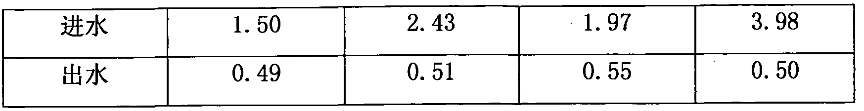
- the utility model relates to an automatic separation and recovery system for oil and water, the structure of which is the same as that of the first and fifth embodiments, but the oil content of the bilge oily sewage to be monitored is large (characteristically different from the oil concentration of the oily sewage in the bilge of the ship).
- the data of the influent and effluent oil content measured by the monitoring unit are as follows (when the influent water content is high): Monitoring results on February 7, 2007 Petroleum (mg/L) sample number
Description


Claims
Priority Applications (4)
| Application Number | Priority Date | Filing Date | Title |
|---|---|---|---|
| KR1020097011234A KR101096538B1 (ko) | 2007-03-13 | 2008-03-03 | 선박용 유수 자동 분리 및 회수 시스템 |
| EP08714878.9A EP2157055B1 (en) | 2007-03-13 | 2008-03-03 | An auto-separation and recovery device for oil-water and a combined marine oil-water auto-separation and recovery system thereof |
| US12/517,114 US8206585B2 (en) | 2007-03-13 | 2008-03-03 | Automatic oil-water separation and recovery system used on ships |
| JP2009552989A JP5491204B2 (ja) | 2007-03-13 | 2008-03-03 | 船舶用油水自動分離及び回収システム |
Applications Claiming Priority (2)
| Application Number | Priority Date | Filing Date | Title |
|---|---|---|---|
| CN200710020574.5 | 2007-03-13 | ||
| CNB2007100205745A CN100480191C (zh) | 2007-03-13 | 2007-03-13 | 一种油水自动分离并回收装置 |
Publications (1)
| Publication Number | Publication Date |
|---|---|
| WO2008110060A1 true WO2008110060A1 (fr) | 2008-09-18 |
Family
ID=38807310
Family Applications (1)
| Application Number | Title | Priority Date | Filing Date |
|---|---|---|---|
| PCT/CN2008/000424 WO2008110060A1 (fr) | 2007-03-13 | 2008-03-03 | Dispositif d'auto-séparation eau-huile et dispositif de récupération, et système les combinant |
Country Status (7)
| Country | Link |
|---|---|
| US (1) | US8206585B2 (zh) |
| EP (1) | EP2157055B1 (zh) |
| JP (1) | JP5491204B2 (zh) |
| KR (1) | KR101096538B1 (zh) |
| CN (1) | CN100480191C (zh) |
| RU (1) | RU2464234C2 (zh) |
| WO (1) | WO2008110060A1 (zh) |
Cited By (1)
| Publication number | Priority date | Publication date | Assignee | Title |
|---|---|---|---|---|
| WO2010139462A2 (fr) | 2009-06-03 | 2010-12-09 | Hoppal R&D Sa | Dispositif de decontamination d'effluents aqueux par separation de phases non miscibles et traitement germicide et/ou oxydant en vue de l'abattement de la dbo et/ou de la dco |
Families Citing this family (11)
| Publication number | Priority date | Publication date | Assignee | Title |
|---|---|---|---|---|
| KR101722590B1 (ko) * | 2010-08-30 | 2017-04-03 | 대우조선해양 주식회사 | 선박용 오염수 회수시스템 |
| CN102689996A (zh) * | 2012-06-16 | 2012-09-26 | 付望新 | 切削液净化用精密处理装置 |
| CN104030465A (zh) * | 2014-03-27 | 2014-09-10 | 深圳市比斯坦科技有限公司 | 一种油水分离系统 |
| WO2016040762A1 (en) * | 2014-09-11 | 2016-03-17 | President And Fellows Of Harvard College | Separation of emulsified and dissolved organic compounds from water |
| CN104548665A (zh) * | 2014-12-02 | 2015-04-29 | 深圳市兰科环境技术有限公司 | 萃取有机相分离回收装置和方法 |
| CN106241952A (zh) * | 2016-09-21 | 2016-12-21 | 神华集团有限责任公司 | 一种油水分离塔及油水分离方法 |
| CN110352089B (zh) * | 2017-02-28 | 2022-03-29 | 伯克哈特压缩机股份公司 | 从气体流中分离润滑剂的装置和方法和压缩可燃气体的系统和方法 |
| CN108841449B (zh) * | 2018-08-29 | 2023-11-03 | 广西壮族自治区林业科学研究院 | 一种精油提取分离装置 |
| CN112221202B (zh) * | 2020-10-26 | 2022-03-22 | 哈尔滨恒通排水设备制造股份有限公司 | 一种对油水分离装置排油称重的远程计量方法及装置 |
| DE102021122131A1 (de) * | 2021-08-26 | 2023-03-02 | Alexander Proch | Abscheidervorrichtung zur Behandlung eines Öl-Wasser-Gemischs |
| CN113816544A (zh) * | 2021-09-09 | 2021-12-21 | 华能嘉祥发电有限公司 | 一种含油废水处理系统 |
Citations (4)
| Publication number | Priority date | Publication date | Assignee | Title |
|---|---|---|---|---|
| US1761505A (en) | 1927-06-07 | 1930-06-03 | White Oil Separators Ltd | Separation of liquids of different specific gravities |
| US4111806A (en) | 1975-08-29 | 1978-09-05 | National Marine Service, Inc. | Gravitational separator for mixtures of immiscible liquids of different densities |
| CN2087530U (zh) | 1991-04-13 | 1991-10-30 | 殷振伟 | 双向双料压力式过滤器 |
| CN1721029A (zh) * | 2005-06-20 | 2006-01-18 | 甘宪 | 油水自动分离并回收装置 |
Family Cites Families (19)
| Publication number | Priority date | Publication date | Assignee | Title |
|---|---|---|---|---|
| US2624463A (en) * | 1949-06-10 | 1953-01-06 | Ernest F Freese | Liquid-separating device |
| US4014791A (en) * | 1972-09-25 | 1977-03-29 | Tuttle Ralph L | Oil separator |
| US3865732A (en) * | 1972-11-27 | 1975-02-11 | Fram Corp | Emulsion breaker |
| NL162846C (nl) * | 1972-12-06 | 1980-07-15 | Nat Marine Service Inc | Inrichting voor het afscheiden van olie uit een mengsel van olie en water. |
| US4102787A (en) * | 1974-02-18 | 1978-07-25 | Machinefabriek Geurtsen Deventer, B.V. | Apparatuses to separate mixtures of liquids of different specific gravities |
| US3937662A (en) * | 1974-05-13 | 1976-02-10 | Keene Corporation | Marine discharge control apparatus and method for treating fluids on a marine vessel |
| US4058463A (en) * | 1974-09-03 | 1977-11-15 | Keene Corporation | Element for filtering and separating fluid mixtures |
| JPS5193472A (en) * | 1975-02-14 | 1976-08-16 | Yusuitono bunrisochi | |
| US4059511A (en) * | 1976-06-28 | 1977-11-22 | Mitsubishi Rayon Co., Ltd. | Method for clarifying waste water containing finely divided oily materials |
| JPS5421801Y2 (zh) * | 1976-07-12 | 1979-08-01 | ||
| US4139463A (en) * | 1977-03-14 | 1979-02-13 | Racor Industries Inc | Method of and means for oily water separation |
| JPS5424365A (en) * | 1977-07-27 | 1979-02-23 | Nippon Esu Aaru Esu Kk | Deeoiling system |
| US4240908A (en) * | 1977-08-05 | 1980-12-23 | Mapco, Inc. | Coated metal fiber coalescing cell |
| JPS5471779A (en) * | 1977-11-21 | 1979-06-08 | Mitsubishi Rayon Co Ltd | Back washing type adsorber |
| SU1111999A1 (ru) * | 1983-06-06 | 1984-09-07 | Среднеазиатский Научно-Исследовательский И Проектно-Конструкторский Институт Пищевой Промышленности | Устройство дл очистки сточных вод |
| US4892667A (en) * | 1988-09-16 | 1990-01-09 | Kaydon Corporation | Method and means for dewatering lubricating oils |
| IT1254964B (it) * | 1992-04-30 | 1995-10-11 | Italtraco | Dispositivo per la separazione dei componenti di miscele di liquidi essenzialmente del tipo acqua/olio, e metodo di separazione che lo utilizza. |
| US5350527A (en) * | 1993-09-14 | 1994-09-27 | Kitko John C | Oily water separation and water reclamation system |
| RU2102112C1 (ru) * | 1995-12-19 | 1998-01-20 | АООТ "Мценский завод коммунального машиностроения" | Установка для очистки сточных вод |
-
2007
- 2007-03-13 CN CNB2007100205745A patent/CN100480191C/zh active Active
-
2008
- 2008-03-03 RU RU2009121637/05A patent/RU2464234C2/ru active IP Right Revival
- 2008-03-03 JP JP2009552989A patent/JP5491204B2/ja active Active
- 2008-03-03 WO PCT/CN2008/000424 patent/WO2008110060A1/zh active Application Filing
- 2008-03-03 US US12/517,114 patent/US8206585B2/en active Active
- 2008-03-03 KR KR1020097011234A patent/KR101096538B1/ko active IP Right Grant
- 2008-03-03 EP EP08714878.9A patent/EP2157055B1/en active Active
Patent Citations (4)
| Publication number | Priority date | Publication date | Assignee | Title |
|---|---|---|---|---|
| US1761505A (en) | 1927-06-07 | 1930-06-03 | White Oil Separators Ltd | Separation of liquids of different specific gravities |
| US4111806A (en) | 1975-08-29 | 1978-09-05 | National Marine Service, Inc. | Gravitational separator for mixtures of immiscible liquids of different densities |
| CN2087530U (zh) | 1991-04-13 | 1991-10-30 | 殷振伟 | 双向双料压力式过滤器 |
| CN1721029A (zh) * | 2005-06-20 | 2006-01-18 | 甘宪 | 油水自动分离并回收装置 |
Non-Patent Citations (1)
| Title |
|---|
| See also references of EP2157055A4 |
Cited By (1)
| Publication number | Priority date | Publication date | Assignee | Title |
|---|---|---|---|---|
| WO2010139462A2 (fr) | 2009-06-03 | 2010-12-09 | Hoppal R&D Sa | Dispositif de decontamination d'effluents aqueux par separation de phases non miscibles et traitement germicide et/ou oxydant en vue de l'abattement de la dbo et/ou de la dco |
Also Published As
| Publication number | Publication date |
|---|---|
| EP2157055A4 (en) | 2011-05-18 |
| US20100065480A1 (en) | 2010-03-18 |
| EP2157055A1 (en) | 2010-02-24 |
| RU2464234C2 (ru) | 2012-10-20 |
| JP5491204B2 (ja) | 2014-05-14 |
| KR101096538B1 (ko) | 2011-12-20 |
| RU2009121637A (ru) | 2011-04-20 |
| CN100480191C (zh) | 2009-04-22 |
| US8206585B2 (en) | 2012-06-26 |
| JP2010521279A (ja) | 2010-06-24 |
| EP2157055B1 (en) | 2013-10-30 |
| KR20090089351A (ko) | 2009-08-21 |
| CN101041481A (zh) | 2007-09-26 |
Similar Documents
| Publication | Publication Date | Title |
|---|---|---|
| WO2008110060A1 (fr) | Dispositif d'auto-séparation eau-huile et dispositif de récupération, et système les combinant | |
| CN206941549U (zh) | 一种新型水面溢油膜回收油装置 | |
| CN109763467B (zh) | 海上石油泄漏污染物回收装置 | |
| CN205953690U (zh) | 一种船舶防污染治理用油水净化装置 | |
| CN206188537U (zh) | 预处理加多级平板陶瓷膜含油废水处理系统 | |
| CN207877443U (zh) | 一种污水厂排污过滤装置 | |
| CN205737977U (zh) | 一种船舶江水/海水总管防泥沙装置 | |
| Ogunbiyi et al. | Oil spill management to prevent desalination plant shutdown from the perspectives of offshore cleanup, seawater intake and onshore pretreatment | |
| CN202280045U (zh) | 广域水面泄漏原油的收集与处理一体化装置 | |
| CN104209004B (zh) | 一种用于水域轻质微量油污回收的膜组件 | |
| CN210419607U (zh) | 一种船用海水淡化设备 | |
| CN207608431U (zh) | 油田含硅水复合处理装置 | |
| CN102418332A (zh) | 广域水面泄漏原油的收集与处理一体化装置 | |
| CN105906087B (zh) | 一种船舶用污水处理装置 | |
| Gohil et al. | Overview on Oil/Water Separation Techniques and Working Principles | |
| CN201971686U (zh) | 一种结合聚结技术和有机吸附技术的含油污水处理系统 | |
| CN202865050U (zh) | 船用淡水净化装置 | |
| CN105776663A (zh) | 一种利用浒苔处理船舶油污水的工艺 | |
| CN109650592A (zh) | 一种船用海水淡化装置 | |
| CN207645951U (zh) | 一种新型气浮机 | |
| CN204939138U (zh) | 一种船用油污水处理装置 | |
| CN213493323U (zh) | 一种船舶用舱底水分离器 | |
| JPS6341115Y2 (zh) | ||
| CN203128344U (zh) | 一种船用双膜法水处理系统 | |
| CN207483502U (zh) | 一种新型循环排污水装置 |
Legal Events
| Date | Code | Title | Description |
|---|---|---|---|
| 121 | Ep: the epo has been informed by wipo that ep was designated in this application |
Ref document number: 08714878 Country of ref document: EP Kind code of ref document: A1 |
|
| WWE | Wipo information: entry into national phase |
Ref document number: 12517114 Country of ref document: US Ref document number: KR Ref document number: 1020097011234 Country of ref document: KR |
|
| WWE | Wipo information: entry into national phase |
Ref document number: 2009552989 Country of ref document: JP |
|
| WWE | Wipo information: entry into national phase |
Ref document number: 2008714878 Country of ref document: EP |
|
| NENP | Non-entry into the national phase |
Ref country code: DE |
|
| WWE | Wipo information: entry into national phase |
Ref document number: 2009121637 Country of ref document: RU |