WO2007019812A1 - Sealing arrangement composed of different types of polymer material - Google Patents

Sealing arrangement composed of different types of polymer material Download PDF

Info

Publication number
WO2007019812A1
WO2007019812A1 PCT/DE2005/001459 DE2005001459W WO2007019812A1 WO 2007019812 A1 WO2007019812 A1 WO 2007019812A1 DE 2005001459 W DE2005001459 W DE 2005001459W WO 2007019812 A1 WO2007019812 A1 WO 2007019812A1
Authority
WO
WIPO (PCT)
Prior art keywords
profile
sealing
arrangement according
sealing arrangement
extruded
Prior art date
Application number
PCT/DE2005/001459
Other languages
German (de)
French (fr)
Inventor
Holger Gutschmidt
Heiko Höft
Andreas Diener
Original Assignee
Phoenix Dichtungstechnik Gmbh
Priority date (The priority date is an assumption and is not a legal conclusion. Google has not performed a legal analysis and makes no representation as to the accuracy of the date listed.)
Filing date
Publication date
Application filed by Phoenix Dichtungstechnik Gmbh filed Critical Phoenix Dichtungstechnik Gmbh
Priority to AT05779627T priority Critical patent/ATE456728T1/en
Priority to US11/989,083 priority patent/US20090148658A1/en
Priority to EP05779627A priority patent/EP1920137B1/en
Priority to ES05779627T priority patent/ES2340300T3/en
Priority to DE112005003732T priority patent/DE112005003732A5/en
Priority to PCT/DE2005/001459 priority patent/WO2007019812A1/en
Priority to DE502005008965T priority patent/DE502005008965D1/en
Publication of WO2007019812A1 publication Critical patent/WO2007019812A1/en

Links

Classifications

    • CCHEMISTRY; METALLURGY
    • C09DYES; PAINTS; POLISHES; NATURAL RESINS; ADHESIVES; COMPOSITIONS NOT OTHERWISE PROVIDED FOR; APPLICATIONS OF MATERIALS NOT OTHERWISE PROVIDED FOR
    • C09KMATERIALS FOR MISCELLANEOUS APPLICATIONS, NOT PROVIDED FOR ELSEWHERE
    • C09K3/00Materials not provided for elsewhere
    • C09K3/10Materials in mouldable or extrudable form for sealing or packing joints or covers
    • EFIXED CONSTRUCTIONS
    • E21EARTH DRILLING; MINING
    • E21DSHAFTS; TUNNELS; GALLERIES; LARGE UNDERGROUND CHAMBERS
    • E21D11/00Lining tunnels, galleries or other underground cavities, e.g. large underground chambers; Linings therefor; Making such linings in situ, e.g. by assembling
    • E21D11/38Waterproofing; Heat insulating; Soundproofing; Electric insulating
    • E21D11/385Sealing means positioned between adjacent lining members
    • CCHEMISTRY; METALLURGY
    • C09DYES; PAINTS; POLISHES; NATURAL RESINS; ADHESIVES; COMPOSITIONS NOT OTHERWISE PROVIDED FOR; APPLICATIONS OF MATERIALS NOT OTHERWISE PROVIDED FOR
    • C09KMATERIALS FOR MISCELLANEOUS APPLICATIONS, NOT PROVIDED FOR ELSEWHERE
    • C09K2200/00Chemical nature of materials in mouldable or extrudable form for sealing or packing joints or covers
    • C09K2200/06Macromolecular organic compounds, e.g. prepolymers
    • C09K2200/0607Rubber or rubber derivatives
    • C09K2200/0612Butadiene-acrylonitrile rubber
    • CCHEMISTRY; METALLURGY
    • C09DYES; PAINTS; POLISHES; NATURAL RESINS; ADHESIVES; COMPOSITIONS NOT OTHERWISE PROVIDED FOR; APPLICATIONS OF MATERIALS NOT OTHERWISE PROVIDED FOR
    • C09KMATERIALS FOR MISCELLANEOUS APPLICATIONS, NOT PROVIDED FOR ELSEWHERE
    • C09K2200/00Chemical nature of materials in mouldable or extrudable form for sealing or packing joints or covers
    • C09K2200/06Macromolecular organic compounds, e.g. prepolymers
    • C09K2200/0615Macromolecular organic compounds, e.g. prepolymers obtained by reactions only involving carbon-to-carbon unsaturated bonds
    • C09K2200/0617Polyalkenes
    • CCHEMISTRY; METALLURGY
    • C09DYES; PAINTS; POLISHES; NATURAL RESINS; ADHESIVES; COMPOSITIONS NOT OTHERWISE PROVIDED FOR; APPLICATIONS OF MATERIALS NOT OTHERWISE PROVIDED FOR
    • C09KMATERIALS FOR MISCELLANEOUS APPLICATIONS, NOT PROVIDED FOR ELSEWHERE
    • C09K2200/00Chemical nature of materials in mouldable or extrudable form for sealing or packing joints or covers
    • C09K2200/06Macromolecular organic compounds, e.g. prepolymers
    • C09K2200/0615Macromolecular organic compounds, e.g. prepolymers obtained by reactions only involving carbon-to-carbon unsaturated bonds
    • C09K2200/0632Polystyrenes
    • CCHEMISTRY; METALLURGY
    • C09DYES; PAINTS; POLISHES; NATURAL RESINS; ADHESIVES; COMPOSITIONS NOT OTHERWISE PROVIDED FOR; APPLICATIONS OF MATERIALS NOT OTHERWISE PROVIDED FOR
    • C09KMATERIALS FOR MISCELLANEOUS APPLICATIONS, NOT PROVIDED FOR ELSEWHERE
    • C09K2200/00Chemical nature of materials in mouldable or extrudable form for sealing or packing joints or covers
    • C09K2200/06Macromolecular organic compounds, e.g. prepolymers
    • C09K2200/0615Macromolecular organic compounds, e.g. prepolymers obtained by reactions only involving carbon-to-carbon unsaturated bonds
    • C09K2200/0635Halogen-containing polymers, e.g. PVC
    • CCHEMISTRY; METALLURGY
    • C09DYES; PAINTS; POLISHES; NATURAL RESINS; ADHESIVES; COMPOSITIONS NOT OTHERWISE PROVIDED FOR; APPLICATIONS OF MATERIALS NOT OTHERWISE PROVIDED FOR
    • C09KMATERIALS FOR MISCELLANEOUS APPLICATIONS, NOT PROVIDED FOR ELSEWHERE
    • C09K2200/00Chemical nature of materials in mouldable or extrudable form for sealing or packing joints or covers
    • C09K2200/06Macromolecular organic compounds, e.g. prepolymers
    • C09K2200/0642Copolymers containing at least three different monomers
    • YGENERAL TAGGING OF NEW TECHNOLOGICAL DEVELOPMENTS; GENERAL TAGGING OF CROSS-SECTIONAL TECHNOLOGIES SPANNING OVER SEVERAL SECTIONS OF THE IPC; TECHNICAL SUBJECTS COVERED BY FORMER USPC CROSS-REFERENCE ART COLLECTIONS [XRACs] AND DIGESTS
    • Y10TECHNICAL SUBJECTS COVERED BY FORMER USPC
    • Y10TTECHNICAL SUBJECTS COVERED BY FORMER US CLASSIFICATION
    • Y10T428/00Stock material or miscellaneous articles
    • Y10T428/24Structurally defined web or sheet [e.g., overall dimension, etc.]
    • Y10T428/24273Structurally defined web or sheet [e.g., overall dimension, etc.] including aperture

Definitions

  • the invention relates to a sealing arrangement consisting at least of:
  • each segment is preferably provided at its abutting side with at least one all segment abutment sides encompassing circumferential recess, which in turn in each recess a strand-shaped sealing profile is, with the formation of a sealing frame with frame corners, wherein the sealing profile with strand-shaped open and / or closed groove grooves which are arranged on the profile base side, as well as also strand-shaped channels extending between the grooves and the profile end face are arranged, is provided.
  • the sealing frame consists of four composite sealing profiles, the frame corners preferably being produced by the injection molding method (EP 0 578 797 B1, EP 1 141 594 B1).
  • a generic sealing arrangement is known, for example, from US Pat. No. 4,946,309, EP 0 441 250 B1 and EP 0 995 013 B1.
  • Such compression seals have been proven in numerous tunnel projects. So far, such sealing profiles are produced by mono-extrusion, on the basis of a uniform material conception.
  • the object of the invention is to provide a sealing arrangement, wherein the material selection of the sealing profile can be adjusted according to the requirements in the interior and exterior of the tunnel structure.
  • the sealing profile consists of two or more co-extruded sealing parts which form an adhesive bond, wherein for the sealing parts at least two different types of polymer materials are used, which together by elastic, but otherwise characterized by different mechanical and / or chemical and / or biological properties.
  • Figure 1 is a tunnel consisting of segments and longitudinal and transverse joints.
  • Fig. 2 shows a sealing arrangement with the gap to be sealed two adjacent
  • Fig. 1 shows a tunnel 1, consisting of segments 2, namely to form transverse and longitudinal joints 3 and 4 and a T-joint arrangement.
  • Fig. 2 shows a sealing assembly 6 with two abutting tunnel segments 2 made of concrete, each with a recess 7 (depth d, base width w) are provided. Sealing profiles of polymeric material with elastic properties are now used in these two recesses, reference being made to the examples according to FIGS. 3 to 9, which will be explained in more detail.
  • the actual sealing of the gap (here in the form of the longitudinal joint 4) is carried out by compressing the opposite sealing profiles (compression seal), wherein the gap distance from S 0 to S is reduced.
  • FIG. 3 now shows a sealing profile 8 of polymeric material comprising a profile base side 9 which corresponds to the recess width w (FIG. 2) and a profile end face 10 which projects beyond the recess depth d (FIG. 2).
  • the sealing profile is provided with strand-shaped groove grooves 11 open and with likewise strand-shaped extending channels 12, which are arranged in two rows (EP 0 441 250 B1).
  • the sealing profile consists of two co-extruded sealing parts A1 and B1, which form in relation to the profile longitudinal plane Y, which is perpendicular to the profile base side 9 or profile end 10, a profile outer segment and a profile inner segment, which are the same size.
  • elastomers based on chloroprene (CR), nitrile rubber (NBR), styrene-butadiene rubber (SBR), an ethylene-propylene-diene copolymer (EPDM) or their blends (eg NBR / SBR) are used.
  • Advantageous elastomer combinations are recorded in Table 1. Table 1
  • the rubber mixture has a crosslinker or crosslinker system.
  • the crosslinker system comprises a crosslinker and / or vulcanization activator and an accelerator.
  • Other common compounding ingredients singly or in particular, are fillers, processing aids, plasticizers, anti-aging agents and stabilizers. In this regard, reference is made to the general state of rubber mixing technology.
  • CR flame retardancy
  • SBR abrasion resistance
  • EPDM weather resistance
  • NBR resistance to swelling to oils, greases and fuels
  • elastomers are here also CR 1 NBR, SBR, EPDM or their blends.
  • thermoplastic styrene-based elastomers TPE-S
  • unblended or partially crosslinked olefin-based thermoplastic elastomers TPE-O
  • fully cross-linked thermoplastic elastomers based on olefin TPE-V
  • crosslinking which is usually the case, the essential constituent of the mixture ingredients is the crosslinker or the crosslinker system.
  • the remaining mixture ingredients may include all raw material components that positively affect the property pattern of the TPE material. These are, for example, fillers, anti-aging agents, stabilizers, flow aids and processing aids. In this regard, reference is made to the general state of TPE technology.
  • TPE material which consists of a blend of a thermoplastic material (thermoplastic) and an at least partially crosslinked rubber, in particular based on EPDM.
  • the preferred plastic used is a polypropylene based on a homopolymer, copolymers or block copolymers.
  • the rubber has a degree of crosslinking of in particular> 90%, wherein a plasticizer is used to stretch the rubber.
  • TPE mixture ingredients also apply here.
  • details (for example, proportions within the TPE mixture) of this preferred TPE material reference is made to DE 103 36 424 A1.
  • the TPE materials are additionally admixed with a surface modifier which migrates uniformly to the surface, to form a continuous, waxy, solid layer (DE 103 36 424 A1). This layer is smooth and allows easy assembly of seals due to the low coefficient of friction.
  • the hardnesses of the individual sealing parts A1 and B1 are possible in order to achieve the desired material properties.
  • the hardnesses can vary between 50 and 90 ° Shore.
  • sealing profile 8 With regard to the sealing profile 8 according to FIG. 3, the following two examples are mentioned in the background of the material technology presented in more detail above, with the sealing part A1 facing the outer tunnel area and the sealing part B1 facing the inner tunnel area.
  • sealing part A1 is produced on the basis of the oil-resistant material NBR, while for the other sealing part B1 a material based on CR, SBR or EPDM is used.
  • the tunnel forms a river crossing, so that the sealing part A1 is in contrast to the sealing part B1 mikrobenstieri, on the basis of a same base material (eg EPDM) or two different materials (Table 1).
  • 4 shows a sealing profile 13 with two sealing parts A2 and B2, which form a base-side and front-side profile segment with respect to the profile longitudinal plane X, which runs parallel to the profile base side 9 or profile end face 10.
  • the base-side profile segment captures exclusively the open groove grooves 11.
  • the front-side sealing part B2 In the case of a sealing profile with such a construction, it is advisable to equip the front-side sealing part B2 with a TPE material to which a surface modifier has been added in order to facilitate the assembly.
  • the base-side sealing part A2 consists of an elastomeric material based on CR, NBR, SBR or EPDM.
  • the profile envelope segment (sealing part B3) which completely surrounds the profile core segment (sealing part A3), is of lesser thickness compared to the profile core segment, wherein preferably the minimum thickness is 2 mm.
  • the sealing member B3 can be made of a harder material, thereby making the seal statically more stable. Thus, the forces acting on the seal forces can be better counteracted by the compression.
  • the sealing profile 15 consists of three co-extruded sealing parts C1, D1 and E1, which form with respect to the profile longitudinal plane Y, which is perpendicular to the profile base side or Profilstimseite, two profile edge segments and a profile inner segment, the two profile edge segments the same size are. It is sufficient if only two different types of polymer materials are used, namely a uniform material for the two sealing parts C1 and E1.
  • Fig. 7 also shows a sealing profile 16 with three co-extruded sealing parts C2, D2 and E2, which is parallel to the profile base side or profile front side with respect to the profile longitudinal plane X 1 , form a base-side and end-side profile segment, wherein between these two profile segments continuous and straight profile strut is arranged.
  • the profile strut preferably has a minimum thickness of 2 mm.
  • the sealing parts C2 and E2 are made of the same material, in contrast to the profile strut (sealing part D2).
  • a sealing profile structure for example, offers to make the profile strut harder (60 to 90 ° Shore) than the other two sealing parts C2 and E2 (50 to 80 ° Shore).
  • the sealing profiles 17 and 18 according to FIGS. 8 and 9 have more than three co-extruded sealing parts, formed from a profile strut system F1 (FIG. 8) or F2 (FIG. 9) and a multipart profiled base system G1 (FIG G2 ( Figure 9), the individual profile segments are separated by the strut formation.
  • the profile strut system wherein the individual struts again preferably have a minimum thickness of 2 mm, harder to equip than the profile base system.
  • Such a material differentiation leads to a sealing profile with a particularly high sealing performance, in particular in connection with a truss-like strut system F1 according to FIG. 8.
  • the sealing member 18 of FIG. 9 is additionally equipped with two anchoring feet 19 (DE 39 34 198 C2).
  • the groove grooves 20 are here in contrast to the sealing profiles of FIG. 3 to 8 closed.
  • the profile region 21 can also be equipped with a receiving groove for a source seal (emergency seal).
  • a source seal (emergency seal).

Abstract

The invention relates to a sealing arrangement composed of at least: two adjoining structural parts (2) made of concrete, steel, reinforced concrete, cast iron or other materials, and a sealing profile (8) which is made of polymer material and sealingly bridges the gap (4) between the two structural parts (2). The sealing arrangement according to the invention is characterized in that: the sealing profile (8) is composed of two or more co-extruded sealing parts (A1, B1) that form an adhesive join, the sealing parts being produced using at least two different types of polymer materials that are distinguished by having common elastic properties but having different mechanical and/or chemical and/or biological properties. Advantageous co-extruded sealing part constructions and material combinations are proposed.

Description

DICHTAMORDNUNG AUS VERSCHIEDENARTIGEN POLYMERWERKSTOFFTYPEN SEAL ASSEMBLY OF VARIOUS POLYMER WORKPIECE TYPES
Beschreibungdescription
Die Erfindung betrifft eine Dichtanordnung, bestehend wenigstens aus:The invention relates to a sealing arrangement consisting at least of:
- zwei aneinander stoßenden Bauteilen aus Beton, Stahl, Stahlbeton, Gusseisen oder anderen Materialien (z.B. Kunstharze) sowie aus einem Dichtprofil aus polymerem Werkstoff, das den Spalt zwischen den beiden Bauteilen abdichtend überbrückt;- two abutting components made of concrete, steel, reinforced concrete, cast iron or other materials (such as synthetic resins) and a sealing profile made of polymeric material, which bridges the gap between the two components in a sealing manner;
- wobei die Bauteile Segmente sind, die zu einem rohrförmigen Tunnel zusammengesetzt sind, und zwar unter Bildung eines Spaltsystems in Form von Quer- und Längsfugen, wobei jedes Segment an seiner Stoßseite vorzugsweise mit wenigstens einer alle Segmentstoßseiten erfassenden umlaufenden Aussparung versehen ist, wobei sich wiederum in jeder Aussparung ein strangförmig verlaufendes Dichtprofil befindet, und zwar unter Bildung eines Dichtrahmens mit Rahmenecken, wobei das Dichtprofil mit strangförmig verlaufenden offenen und/oder geschlossenen Rillennuten, die an der Profilbasisseite angeordnet sind, sowie mit ebenfalls strangförmig verlaufenden Kanälen, die zwischen den Rillennuten und der Profilstirnseite angeordnet sind, versehen ist.- The components are segments that are assembled into a tubular tunnel, and to form a gap system in the form of transverse and longitudinal joints, each segment is preferably provided at its abutting side with at least one all segment abutment sides encompassing circumferential recess, which in turn in each recess a strand-shaped sealing profile is, with the formation of a sealing frame with frame corners, wherein the sealing profile with strand-shaped open and / or closed groove grooves which are arranged on the profile base side, as well as also strand-shaped channels extending between the grooves and the profile end face are arranged, is provided.
Da die Segmente zumeist vier Stoßseiten besitzen, besteht der Dichtrahmen aus vier zusammengesetzten Dichtprofilen, wobei die Rahmenecken vorzugsweise nach dem Injection-Molding-Verfahren hergestellt werden (EP 0 578 797 B1 , EP 1 141 594 B1 ).Since the segments usually have four abutting sides, the sealing frame consists of four composite sealing profiles, the frame corners preferably being produced by the injection molding method (EP 0 578 797 B1, EP 1 141 594 B1).
Eine gattungsgemäße Dichtanordnung ist beispielsweise aus der US 4 946 309, EP 0 441 250 B1 und EP 0 995 013 B1 bekannt. Infolge des Zusammenpressens der aneinander stoßenden Bauteile bzw. Segmente unter Verringerung des Abstandes des Spaltes bzw. der Quer- und Längsfugen entfaltet dann das Dichtprofil aus elastomerem Werkstoff unter der Wechselwirkung von Kraft und Reaktionskraft seine Dichtleistung. Derartige Kompressionsdichtungen haben sich bei zahlreichen Tunnelprojekten bewährt. Bislang werden derartige Dichtprofile durch Monoextrusion hergestellt, und zwar auf der Basis einer einheitlichen Werkstoff konzeption.A generic sealing arrangement is known, for example, from US Pat. No. 4,946,309, EP 0 441 250 B1 and EP 0 995 013 B1. As a result of compressing the abutting components or segments while reducing the distance of the gap or the transverse and longitudinal joints then unfolds the sealing profile of elastomeric material under the interaction of force and reaction force its sealing performance. Such compression seals have been proven in numerous tunnel projects. So far, such sealing profiles are produced by mono-extrusion, on the basis of a uniform material conception.
Im Rahmen einer Weiterentwicklung besteht die Aufgabe der Erfindung darin, eine Dichtanordnung bereitzustellen, wobei die Materialauswahl des Dichtprofiles entsprechend den Anforderungen im Inneren und Äußeren des Tunnelbauwerkes angepasst werden kann.In a further development, the object of the invention is to provide a sealing arrangement, wherein the material selection of the sealing profile can be adjusted according to the requirements in the interior and exterior of the tunnel structure.
Gelöst wird diese Aufgabe gemäß Kennzeichen des Patentanspruches 1 dadurch, dass das Dichtprofil aus zwei oder mehreren co-extrudierten Dichtteilen, die einen Haftverbund bilden, besteht, wobei für die Dichtteile wenigstens zwei verschiedenartige Polymerwerkstofftypen zum Einsatz gelangen, die sich gemeinsam durch elastische, jedoch ansonsten durch unterschiedliche mechanische und/oder chemische und/oder biologische Eigenschaften auszeichnen.This object is achieved according to the characterizing part of claim 1, characterized in that the sealing profile consists of two or more co-extruded sealing parts which form an adhesive bond, wherein for the sealing parts at least two different types of polymer materials are used, which together by elastic, but otherwise characterized by different mechanical and / or chemical and / or biological properties.
Zweckmäßige Ausgestaltungen der Erfindung sind in den Patentansprüchen 2 bis 26 genannt.Advantageous embodiments of the invention are mentioned in the claims 2 to 26.
Die Erfindung wird nun anhand von Ausführungsbeispielen unter Bezugnahme auf schematische Zeichnungen erläutert. Es zeigen:The invention will now be explained by means of exemplary embodiments with reference to schematic drawings. Show it:
Fig. 1 einen Tunnel, bestehend aus Segmenten sowie Längs- und Querfugen;Figure 1 is a tunnel consisting of segments and longitudinal and transverse joints.
Fig. 2 eine Dichtanordnung mit dem abzudichtenden Spalt zweier angrenzenderFig. 2 shows a sealing arrangement with the gap to be sealed two adjacent
Tunnel-Segmente gemäß Schnittlinie (Fig. 1);Tunnel segments according to section line (Figure 1);
Fig. 3, 4, 5 Dichtprofile mit zwei co-extrudierten Dichtteilen;Fig. 3, 4, 5 sealing profiles with two co-extruded sealing parts;
Fig. 6, 7 Dichtprofile mit drei co-extrudierten Dichtteilen;Fig. 6, 7 sealing profiles with three co-extruded sealing parts;
Fig. 8, 9 Dichtprofile mit mehr als drei co-extrudierten Dichtteilen.Fig. 8, 9 sealing profiles with more than three co-extruded sealing parts.
Fig. 1 zeigt einen Tunnel 1, bestehend aus Segmenten 2, und zwar unter Bildung von Quer- und Längsfugen 3 bzw. 4 sowie einer T-Stoßanordnung 5. Fig. 2 zeigt eine Dichtanordnung 6 mit zwei aneinander stoßenden Tunnel-Segmenten 2 aus Beton, die jeweils mit einer Aussparung 7 (Tiefe d, Basisbreite w) versehen sind. In diese beiden Aussparungen werden nun Dichtprofile aus polymerem Werkstoff mit elastischen Eigenschaften eingesetzt, wobei auf die Beispiele gemäß Fig. 3 bis 9, die noch näher erläutert werden, verwiesen wird. Die eigentliche Abdichtung des Spaltes (hier in Form der Längsfuge 4) erfolgt durch das Zusammenpressen der gegenüberliegenden Dichtprofile (Kompressionsdichtung), wobei der Spaltabstand von S0 auf S verringert wird. Beim Bau von Tunneln muss dabei in Erwägung gezogen werden, dass die Segmente 2 unter einem Versatz Z zueinander angeordnet sind. Dabei wird von den Dichtprofilen erwartet, dass sie auch unter diesem tunnelspezifischen Kriterium ihre Dichtleistung entfalten. Diesbezüglich sind schon zahlreiche Hochleistungsdichtungen entwickelt worden, wobei beispielsweise auf den eingangs zitierten Stand der Technik verwiesen wird. Eine besonders häufig eingesetzte Tunneldichtung ist in der Patentschrift EP 0 441 250 B1 beschrieben.Fig. 1 shows a tunnel 1, consisting of segments 2, namely to form transverse and longitudinal joints 3 and 4 and a T-joint arrangement. 5 Fig. 2 shows a sealing assembly 6 with two abutting tunnel segments 2 made of concrete, each with a recess 7 (depth d, base width w) are provided. Sealing profiles of polymeric material with elastic properties are now used in these two recesses, reference being made to the examples according to FIGS. 3 to 9, which will be explained in more detail. The actual sealing of the gap (here in the form of the longitudinal joint 4) is carried out by compressing the opposite sealing profiles (compression seal), wherein the gap distance from S 0 to S is reduced. In the construction of tunnels it must be considered that the segments 2 are arranged at an offset Z to each other. It is expected of the sealing profiles that they unfold their sealing performance under this tunnel-specific criterion. In this regard, numerous high performance seals have been developed, for example, reference is made to the cited prior art. An especially frequently used tunnel seal is described in the patent EP 0 441 250 B1.
Fig. 3 zeigt nun ein Dichtprofil 8 aus polymerem Werkstoff, umfassend eine Profilbasisseite 9, die der Aussparungsbreite w (Fig. 2) entspricht, und eine Profilstirnseite 10, die über die Aussparungstiefe d (Fig. 2) herausragt. Das Dichtprofil ist mit strangförmig verlaufend offenen Rillenuten 11 sowie mit ebenfalls strangförmig verlaufenden Kanälen 12 versehen, die zweireihig angeordnet sind (EP 0 441 250 B1 ).3 now shows a sealing profile 8 of polymeric material comprising a profile base side 9 which corresponds to the recess width w (FIG. 2) and a profile end face 10 which projects beyond the recess depth d (FIG. 2). The sealing profile is provided with strand-shaped groove grooves 11 open and with likewise strand-shaped extending channels 12, which are arranged in two rows (EP 0 441 250 B1).
Das Dichtprofil besteht aus zwei co-extrudierten Dichtteilen A1 und B1 , die in Bezug auf die Profillängsebene Y, die senkrecht zur Profilbasisseite 9 bzw. Profilstirnseite 10 verläuft, ein Profilaußensegment und ein Profilinnensegment bilden, die gleich groß sind.The sealing profile consists of two co-extruded sealing parts A1 and B1, which form in relation to the profile longitudinal plane Y, which is perpendicular to the profile base side 9 or profile end 10, a profile outer segment and a profile inner segment, which are the same size.
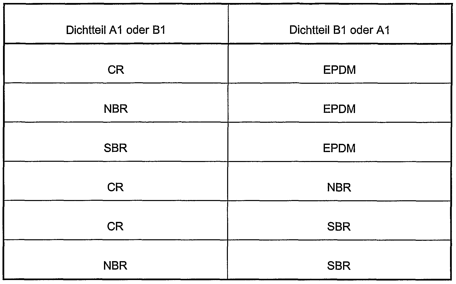
Für die beiden Dichtteile A1 und B1 können Elastomere auf der Basis von Chloropren (CR), Nitrilkautschuk (NBR), Styrol-Butadien-Kautschuk (SBR), eines Ethylen- Propylen-Dien-Mischpolymerisates (EPDM) oder deren Verschnitte (z.B. NBR/SBR) zur Anwendung kommen. Vorteilhaft Elastomerkombinationen sind in der Tabelle 1 festgehalten. Tabelle 1For the two sealing parts A1 and B1, elastomers based on chloroprene (CR), nitrile rubber (NBR), styrene-butadiene rubber (SBR), an ethylene-propylene-diene copolymer (EPDM) or their blends (eg NBR / SBR) are used. Advantageous elastomer combinations are recorded in Table 1. Table 1
Figure imgf000006_0001
Hier handelt es sich dabei um eine vulkanisierte Kautschukmischung, wobei die oben genannten Kautschuk- bzw. Verschnittkomponenten jeweils zumeist in einem Anteil von 30 bis 70 Gew.-% vorkommen. Die Kautschukmischung weist einen Vernetzer oder Vernetzersystem auf. Das Vernetzersystem umfasst dabei einen Vernetzer und/oder Vulkanisationsaktivator sowie einen Beschleuniger auf. Weitere übliche Mischungsingredienzien, und zwar einzeln oder insbesondere kombinativ, sind Füllstoffe, Verarbeitungshilfsmittel, Weichmacher, Alterungsschutzmittel und Stabilisatoren. Diesbezüglich wird auf den allgemeinen Stand der Kautschukmischungstechnologie verwiesen.This is a vulcanized rubber mixture, wherein the abovementioned rubber or blending components usually occur in each case in a proportion of 30 to 70 wt .-%. The rubber mixture has a crosslinker or crosslinker system. The crosslinker system comprises a crosslinker and / or vulcanization activator and an accelerator. Other common compounding ingredients, singly or in particular, are fillers, processing aids, plasticizers, anti-aging agents and stabilizers. In this regard, reference is made to the general state of rubber mixing technology.
Neben guten elastischen Eigenschaften all dieser Werkstofftypen (CR, NBR, SBR, EPDM) zeichnen sich diese auch durch individuelle Kriterien aus, nämlich Schwerentflammbarkeit (CR), Abriebfestigkeit (SBR), Witterungsbeständigkeit (EPDM) sowie Quellbeständigkeit gegen Öle, Fette und Treibstoffe (NBR).In addition to the good elastic properties of all these types of materials (CR, NBR, SBR, EPDM), these are also distinguished by individual criteria, namely flame retardancy (CR), abrasion resistance (SBR), weather resistance (EPDM) and resistance to swelling to oils, greases and fuels (NBR ).
Auch folgende Werkstoffkombinationen gemäß Tabelle 2 sind anwendbar. Tabelle 2The following material combinations according to Table 2 are applicable. Table 2
Figure imgf000007_0001
Zweckmäßige Basis der Elastomere sind auch hier CR1 NBR, SBR, EPDM oder deren Verschnitte.Appropriate basis of the elastomers are here also CR 1 NBR, SBR, EPDM or their blends.
Was die TPE-Gruppen betrifft, so gelangen vorzugsweise thermoplastische Elastomere auf Styrolbasis (TPE-S), unvemetzte oder teilvernetzte thermoplastische Elastomere auf OIefinbasis (TPE-O) oder vollvernetzte thermoplastische Elastomere auf OIefinbasis (TPE-V) zur Anwendung. Soweit eine Vernetzung vorliegt, was zumeist der Fall ist, ist der wesentliche Bestandteil der Mischungsingredienzien der Vernetzer bzw. das Vernetzersystem. Die übrigen Mischungsingredienzien können alle Rohstoffkomponenten umfassen, die das Eigenschaftsbild des TPE-Werkstoffes positiv beeinflussen. Dies sind zum Beispiel Füllstoffe, Alterungsschutzmittel, Stabilisatoren, Fließhilfsmittel und Prozesshilfsmittel. Diesbezüglich wird auf den allgemeinen Stand der TPE-Technologie verwiesen.As regards the TPE groups, preferably thermoplastic styrene-based elastomers (TPE-S), unblended or partially crosslinked olefin-based thermoplastic elastomers (TPE-O) or fully cross-linked thermoplastic elastomers based on olefin (TPE-V) are used. As far as crosslinking is present, which is usually the case, the essential constituent of the mixture ingredients is the crosslinker or the crosslinker system. The remaining mixture ingredients may include all raw material components that positively affect the property pattern of the TPE material. These are, for example, fillers, anti-aging agents, stabilizers, flow aids and processing aids. In this regard, reference is made to the general state of TPE technology.
Von besonderer Bedeutung ist ein TPE-Werkstoff, der aus einem Verschnitt aus einem thermoplastischen Kunststoff (Thermoplast) und einem mindestens teilvernetzten Kautschuk, insbesondere auf Basis EPDM, besteht. Der bevorzugt eingesetzte Kunststoff ist ein Polypropylen auf der Basis eines Homopolymeren, Copolymeren oder Blockcopolymeren. Der Kautschuk weist einen Vernetzungsgrad von insbesondere > 90 % auf, wobei zum Verstrecken des Kautschuks ein Weichmacher eingesetzt wird. Ansonsten gelten auch hier die oben genannten TPE- Mischungsingredienzien. Hinsichtlich Details (z.B. Mengenanteile innerhalb der TPE-Mischung) dieses bevorzugten TPE-Werkstoffes wird auf die Druckschrift DE 103 36 424 A1 verwiesen. Im Rahmen einer neueren Entwicklung wird den TPE-Werkstoffen zusätzlich ein Oberflächenmodifikator beigemischt, der gleichmäßig an die Oberfläche migriert, und zwar unter Bildung einer durchgehenden, wachsartigen, festen Schicht (DE 103 36 424 A1). Diese Schicht ist glatt und ermöglicht aufgrund des niedrigen Reibungskoeffizienten eine einfache Montage von Dichtungen.Of particular importance is a TPE material, which consists of a blend of a thermoplastic material (thermoplastic) and an at least partially crosslinked rubber, in particular based on EPDM. The preferred plastic used is a polypropylene based on a homopolymer, copolymers or block copolymers. The rubber has a degree of crosslinking of in particular> 90%, wherein a plasticizer is used to stretch the rubber. Otherwise, the above-mentioned TPE mixture ingredients also apply here. With regard to details (for example, proportions within the TPE mixture) of this preferred TPE material, reference is made to DE 103 36 424 A1. As part of a more recent development, the TPE materials are additionally admixed with a surface modifier which migrates uniformly to the surface, to form a continuous, waxy, solid layer (DE 103 36 424 A1). This layer is smooth and allows easy assembly of seals due to the low coefficient of friction.
Darüber hinaus ist es bekannt, den Polymerwerkstoffen, insbesondere den Elastomerwerkstoffen, einen aktiven Inhibitor beizumischen, der die Vermehrung von Mikroorganismen verhindert. Dieser mikrobenbeständige Werkstoff mit biologischen Eigenschaften ist bei Dichtprofilen mit Wasserkontakt von Bedeutung. Diesbezüglich wird insbesondere auf die Druckschrift DE 102 58 551 A1 verwiesen, die sich mit einer mikrobenbeständigen Klärbeckenmembran befasst. Die Mikrobenbeständigkeit polymerer Werkstoffe nimmt an Bedeutung zu.Moreover, it is known to admix the polymer materials, in particular the elastomer materials, an active inhibitor which prevents the proliferation of microorganisms. This microbe-resistant material with biological properties is important for sealing profiles with water contact. In this regard, reference is made in particular to the document DE 102 58 551 A1, which deals with a microbe-resistant clarifier membrane. The microbial resistance of polymeric materials is becoming more important.
Weiterhin sind auch unterschiedliche Härten der einzelnen Dichtteile A1 und B1 möglich, um die gewünschten Stoffeigenschaften zu erzielen. Die Härten können dabei zwischen 50 und 90° Shore variieren. Es ist jedoch ebenso möglich, dass die beiden co-extrudierten Dichtteile die gleiche Härte besitzen, was bei dem Ausführungsbeispiel gemäß Fig. 3 zumeist der Fall ist.Furthermore, different hardnesses of the individual sealing parts A1 and B1 are possible in order to achieve the desired material properties. The hardnesses can vary between 50 and 90 ° Shore. However, it is also possible that the two co-extruded sealing parts have the same hardness, which in the embodiment of FIG. 3 is usually the case.
In Bezug auf das Dichtprofil 8 nach Fig. 3 wird im Hintergrund der oben näher vorgestellten Werkstofftechnologie folgende zwei Beispiele genannt, wobei jeweils das Dichtteil A1 dem Tunnelaußenbereich und das Dichtteil B1 dem Tunnelinnenbereich zugewandt ist.With regard to the sealing profile 8 according to FIG. 3, the following two examples are mentioned in the background of the material technology presented in more detail above, with the sealing part A1 facing the outer tunnel area and the sealing part B1 facing the inner tunnel area.
- Führt der Tunnel unterirdisch durch ein Industriegebiet, so ist es zweckmäßig, wenn Dichtteil A1 auf der Basis des ölbeständigen Werkstoffes NBR hergestellt ist, während für das andere Dichtteil B1 ein Werkstoff auf der Basis CR, SBR oder EPDM zur Anwendung kommt.- If the tunnel passes underground through an industrial area, then it is expedient if sealing part A1 is produced on the basis of the oil-resistant material NBR, while for the other sealing part B1 a material based on CR, SBR or EPDM is used.
- Der Tunnel bildet eine Flussunterquerung, so dass das Dichtteil A1 im Gegensatz zu dem Dichtteil B1 mikrobenständig ist, und zwar auf der Basis eines gleichen Grundwerkstoffes (z.B. EPDM) oder zweier verschiedenartiger Werkstoffe (Tabelle 1). Fig. 4 zeigt ein Dichtprofil 13 mit zwei Dichtteilen A2 und B2, die in Bezug auf die Profillängsebene X, die parallel zur Profilbasisseite 9 bzw. Profilstirnseite 10 verläuft, ein basisseitiges und stirnseitiges Profilsegment bilden. Das basisseitige Profilsegment erfasst dabei ausschließlich die offenen Rillennuten 11.- The tunnel forms a river crossing, so that the sealing part A1 is in contrast to the sealing part B1 mikrobenständig, on the basis of a same base material (eg EPDM) or two different materials (Table 1). 4 shows a sealing profile 13 with two sealing parts A2 and B2, which form a base-side and front-side profile segment with respect to the profile longitudinal plane X, which runs parallel to the profile base side 9 or profile end face 10. The base-side profile segment captures exclusively the open groove grooves 11.
Bei einem Dichtprofil mit einem derartigen Aufbau bietet sich an, das stirnseitige Dichtteil B2 mit einem TPE-Werkstoff auszurüsten, dem ein Oberflächenmodifikator beigemischt ist, um die Montage zu erleichtern. Das basisseitige Dichtteil A2 besteht dagegen aus einem elastomerem Werkstoff auf der Basis CR, NBR, SBR oder EPDM.In the case of a sealing profile with such a construction, it is advisable to equip the front-side sealing part B2 with a TPE material to which a surface modifier has been added in order to facilitate the assembly. By contrast, the base-side sealing part A2 consists of an elastomeric material based on CR, NBR, SBR or EPDM.
Fig. 5 zeigt ein Dichtprofil 14 mit den Dichtteilen A3 und B3, und zwar unter Ausbildung eines Profilkernsegmentes und Profilhüllensegmentes. Das Profilhüllensegment (Dichtteil B3), das vollständig das Profilkernsegment (Dichtteil A3) ummantelt, ist dabei im Vergleich zum Profilkernsegment von geringerer Stärke, wobei vorzugsweise die Mindeststärke 2 mm beträgt.5 shows a sealing profile 14 with the sealing parts A3 and B3, to form a profile core segment and profile shell segment. The profile envelope segment (sealing part B3), which completely surrounds the profile core segment (sealing part A3), is of lesser thickness compared to the profile core segment, wherein preferably the minimum thickness is 2 mm.
Bei einem Dichtprofil gemäß Fig. 5 bietet sich an, beispielsweise ausschließlich das hüllenförmige Dichtteil B3 öl- oder mikrobenbeständig auszurüsten. Außerdem kann das Dichtteil B3 aus einem härteren Material hergestellt werden, so dass dadurch die Dichtung statisch stabiler wird. Damit kann den auf die Dichtung wirkenden Kräften durch die Kompression besser entgegengewirkt werden.In the case of a sealing profile according to FIG. 5, it is advisable, for example, to equip only the envelope-shaped sealing part B3 resistant to oil or microbes. In addition, the sealing member B3 can be made of a harder material, thereby making the seal statically more stable. Thus, the forces acting on the seal forces can be better counteracted by the compression.
Nach Fig. 6 besteht das Dichtprofil 15 aus drei co-extrudierten Dichtteilen C1 , D1 und E1 , die in Bezug auf die Profillängsebene Y, die senkrecht zur Profilbasisseite bzw. Profilstimseite verläuft, zwei Profilrandsegmente und ein Profilinnensegment bilden, wobei die beiden Profilrandsegmente gleich groß sind. Dabei ist es ausreichend, wenn ausschließlich zwei verschiedenartige Polymerwerkstofftypen zur Anwendung kommen, nämlich ein einheitlicher Werkstoff für die beiden Dichtteile C1 und E1.According to Fig. 6, the sealing profile 15 consists of three co-extruded sealing parts C1, D1 and E1, which form with respect to the profile longitudinal plane Y, which is perpendicular to the profile base side or Profilstimseite, two profile edge segments and a profile inner segment, the two profile edge segments the same size are. It is sufficient if only two different types of polymer materials are used, namely a uniform material for the two sealing parts C1 and E1.
Auch bei einem Dichtprofil gemäß Fig. 6 bietet sich an, beispielsweise ausschließlich die beiden Randdichtteile C1 und E1 öl- oder mikrobenständig auszurüsten. Auch wird es hier möglich, die beiden Randdichtteile aus einem härteren Material herzustellen, und zwar zwecks Stabilisierung der Dichtung. Fig. 7 zeigt ebenfalls ein Dichtprofil 16 mit drei co-extrudierten Dichtteilen C2, D2 und E2, die in Bezug auf die Profillängsebene X1 die parallel zur Profilbasisseite bzw. Profilstirnseite verläuft, ein basisseitiges und stirnseitiges Profilsegment bilden, wobei zwischen diesen beiden Profilsegmenten eine durchgehend und gerade verlaufende Profilstrebe angeordnet ist. Die Profilstrebe hat vorzugsweise eine Mindeststärke von 2 mm.Even with a sealing profile according to FIG. 6, it is advisable, for example, exclusively to equip the two edge sealing parts C1 and E1 with oil or microcentricity. Also, it is possible here to produce the two edge sealing parts of a harder material, specifically for the purpose of stabilizing the seal. Fig. 7 also shows a sealing profile 16 with three co-extruded sealing parts C2, D2 and E2, which is parallel to the profile base side or profile front side with respect to the profile longitudinal plane X 1 , form a base-side and end-side profile segment, wherein between these two profile segments continuous and straight profile strut is arranged. The profile strut preferably has a minimum thickness of 2 mm.
Die Dichtteile C2 und E2 bestehen aus dem gleichen Werkstoff, und zwar im Gegensatz zu der Profilstrebe (Dichtteil D2). Bei einem derartigen Dichtprofilaufbau bietet sich beispielsweise an, die Profilstrebe härter (60 bis 90° Shore) zu machen als die beiden anderen Dichtteile C2 und E2 (50 bis 80° Shore).The sealing parts C2 and E2 are made of the same material, in contrast to the profile strut (sealing part D2). In such a sealing profile structure, for example, offers to make the profile strut harder (60 to 90 ° Shore) than the other two sealing parts C2 and E2 (50 to 80 ° Shore).
Die Dichtprofile 17 und 18 gemäß Fig. 8 und 9 weisen mehr als drei co-extrudierte Dichtteile auf, gebildet aus einem Profilstrebensystem F1 (Fig. 8) bzw. F2 (Fig. 9) und einem mehrteiligen Profilbasissystem G1 (Fig. 8) bzw. G2 (Fig. 9), dessen einzelnen Profilsegmente durch die Strebenbildung voneinander getrennt sind. Von besonderer Bedeutung ist hier, das Profilstrebensystem, wobei die einzelnen Streben wiederum vorzugsweise eine Mindeststärke von 2 mm aufweisen, härter auszustatten als das Profilbasissystem. Eine derartige Werkstoffdifferenzierung führt zu einem Dichtprofil mit besonders hoher Dichtleistung, insbesondere in Verbindung mit einem fachwerkartigen Strebensystem F1 gemäß Fig. 8.The sealing profiles 17 and 18 according to FIGS. 8 and 9 have more than three co-extruded sealing parts, formed from a profile strut system F1 (FIG. 8) or F2 (FIG. 9) and a multipart profiled base system G1 (FIG G2 (Figure 9), the individual profile segments are separated by the strut formation. Of particular importance here is the profile strut system, wherein the individual struts again preferably have a minimum thickness of 2 mm, harder to equip than the profile base system. Such a material differentiation leads to a sealing profile with a particularly high sealing performance, in particular in connection with a truss-like strut system F1 according to FIG. 8.
Das Dichtteil 18 gemäß Fig. 9 ist zusätzlich mit zwei Verankerungsfüßen 19 ausgestattet (DE 39 34 198 C2). Die Rillennuten 20 sind hier im Gegensatz zu den Dichtprofilen gemäß Fig. 3 bis 8 geschlossen. Der Profilbereich 21 kann ferner mit einer Aufnahmenut für eine Quelldichtung (Notdichtung) ausgestattet sein. Diesbezüglich wird beispielsweise auf die beiden Patentschriften EP 0 807 204 B1 und EP 0 811 113 B1 verwiesen.The sealing member 18 of FIG. 9 is additionally equipped with two anchoring feet 19 (DE 39 34 198 C2). The groove grooves 20 are here in contrast to the sealing profiles of FIG. 3 to 8 closed. The profile region 21 can also be equipped with a receiving groove for a source seal (emergency seal). In this regard, reference is made, for example, to the two patents EP 0 807 204 B1 and EP 0 811 113 B1.
Der Haftverbund zwischen den co-extrudierten Dichtteilen, wie sie beispielsweise in den Fig. 3 bis 9 dargestellt sind, wird im Rahmen der Co-Extrusion unter Temperatur und Druck gebildet. BezugszeichenlisteThe adhesive bond between the co-extruded sealing parts, as shown for example in Figs. 3 to 9, is formed in the context of co-extrusion under temperature and pressure. LIST OF REFERENCE NUMBERS
1 Tunnel1 tunnel
2 Segment2 segment
3 Querfuge (Ringfuge)3 transverse joint (ring joint)
4 Längsfuge4 longitudinal joint
5 T-Stoßanordnung5 T-joint arrangement
6 Dichtanordnung6 sealing arrangement
7 Aussparung7 recess
8 Dichtprofil8 sealing profile
9 Profilbasisseite9 profile base page
10 Profilstirnseite10 profile front side
11 Rillennuten11 grooves
12 Kanäle12 channels
13 Dichtprofil13 sealing profile
14 Dichtprofil14 sealing profile
15 Dichtprofil15 sealing profile
16 Dichtprofil16 sealing profile
17 Dichtprofil17 sealing profile
18 Dichtprofil18 sealing profile
19 Verankerungsfuß19 anchoring foot
20 geschlossene Rillennuten20 closed grooves
21 Profilbereich mit Aufnahmenut für Quelldichtung A1 , A2, A2 co-extrudierte Dichtteile21 Profile area with receiving groove for source seal A1, A2, A2 co-extruded sealing parts
B1 , B2, B3 co-extrudierte DichtteileB1, B2, B3 co-extruded sealing parts
C1 , C2 co-extrudierte DichtteileC1, C2 co-extruded sealing parts
D1 , D2 co-extrudierte DichtteileD1, D2 co-extruded sealing parts
E1 , E2 co-extrudierte DichtteileE1, E2 co-extruded sealing parts
F1 , F2 co-extrudierte DichtteileF1, F2 co-extruded sealing parts
G1 , G2 co-extrudierte DichtteileG1, G2 co-extruded sealing parts
X, Y ProfillängsebenenX, Y profile longitudinal planes
Z SegmentversatzZ segment offset
S0 Spaltabstand (vor dem Zusammenpressen) S Spaltabstand (nach dem Zusammenpressen) d Tiefe der Aussparung w Basisbreite der Aussparung S 0 gap distance (before compression) S gap distance (after compression) d depth of the recess w base width of the recess

Claims

Patentansprüche claims
1. Dichtanordnung (6), bestehend wenigstens aus:1. sealing arrangement (6), consisting at least of:
- zwei aneinander stoßenden Bauteilen aus Beton, Stahl, Stahlbeton, Gusseisen oder anderen Materialien sowie aus einem Dichtprofil aus polymerem Werkstoff, das den Spalt zwischen den beiden Bauteilen abdichtend überbrückt;- Two abutting components made of concrete, steel, reinforced concrete, cast iron or other materials and a sealing profile made of polymeric material, which bridges the gap between the two components sealingly;
- wobei die Bauteile Segmente (2) sind, die zu einem rohrförmigen Tunnel (1) zusammengesetzt sind, und zwar unter Bildung eines Spaltsystems in Form von Quer- und Längsfugen (3, 4), wobei jedes Segment an seiner Stoßseite vorzugsweise mit wenigstens einer alle Segmentstoßseiten erfassenden umlaufenden Aussparung (7) versehen ist, wobei sich wiederum in jeder Aussparung ein strangförmig verlaufendes Dichtprofil (8, 13, 14, 15, 16, 17, 18) befindet, und zwar unter Bildung eines Dichtrahmens mit Rahmenecken, wobei das Dichtprofil mit strangförmig verlaufenden offenen und/oder geschlossenen Rillennuten (11 , 20), die an der Profilbasisseite (9) angeordnet sind, sowie mit ebenfalls strangförmig verlaufenden Kanälen (12), die zwischen den Rillennuten und der Profilstirnseite (10) angeordnet sind, versehen ist;- The components are segments (2), which are assembled into a tubular tunnel (1), to form a gap system in the form of transverse and longitudinal joints (3, 4), each segment at its abutment side preferably with at least one all segment abutting sides encompassing circumferential recess (7) is provided, which in turn is in each recess a strand-shaped sealing profile (8, 13, 14, 15, 16, 17, 18) is located, to form a sealing frame with frame corners, wherein the sealing profile with strand-like open and / or closed groove grooves (11, 20), which are arranged on the profile base side (9), and also with strand-like running channels (12), which are arranged between the groove grooves and the profile end face (10) is provided ;
dadurch gekennzeichnet, dasscharacterized in that
- das Dichtprofil (8, 13, 14, 15, 16, 17, 18) aus zwei oder mehreren co- extrudierten Dichtteilen, die einen Haftverbund bilden, besteht, wobei für die Dichtteile wenigstens zwei verschiedenartige Polymerwerkstofftypen zum Einsatz gelangen, die sich gemeinsam durch elastische, jedoch ansonsten durch unterschiedliche mechanische und/oder chemische und/oder biologische Eigenschaften auszeichnen. - The sealing profile (8, 13, 14, 15, 16, 17, 18) consists of two or more co-extruded sealing parts which form an adhesive bond, wherein for the sealing parts at least two different types of polymer materials are used, which together by elastic, but otherwise characterized by different mechanical and / or chemical and / or biological properties.
2. Dichtanordnung nach Anspruch 1 , dadurch gekennzeichnet, dass zwei co- extrudierte Dichtteile (A1, B1) vorhanden sind, die in Bezug auf die Profillängsebene Y, die senkrecht zur Profilbasisseite (9) bzw. Profilstirnseite (10) verläuft, ein Profilaußensegment und Profilinnensegment bilden, wobei die beiden Profilsegmente insbesondere gleich groß sind.2. Sealing arrangement according to claim 1, characterized in that two co-extruded sealing parts (A1, B1) are present, with respect to the profile longitudinal plane Y, which is perpendicular to the profile base side (9) or profile end face (10), a profile outer segment and Form profile inner segment, the two profile segments are in particular the same size.
3. Dichtanordnung nach Anspruch 1 , dadurch gekennzeichnet, dass zwei co- extrudierte Dichtteile (A2, B2) vorhanden sind, die in Bezug auf die Profillängsebene X, die parallel zur Profilbasisseite (9) bzw. Profilstirnseite (10) verläuft, ein basisseitiges und stirnseitiges Profilsegment bilden.3. Sealing arrangement according to claim 1, characterized in that two co-extruded sealing parts (A2, B2) are present, with respect to the profile longitudinal plane X, which is parallel to the profile base side (9) or profile end face (10), a base-side and form the frontal profile segment.
4. Dichtanordnung nach Anspruch 3, dadurch gekennzeichnet, dass das basisseitige Profilsegment ausschließlich die offenen und/oder geschlossenen Rillennuten (11 , 20) erfasst.4. Sealing arrangement according to claim 3, characterized in that the base-side profile segment detects only the open and / or closed groove grooves (11, 20).
5. Dichtanordnung nach Anspruch 1 , dadurch gekennzeichnet, dass zwei co- extrudierte Dichtteile (A3, B3) vorhanden sind, und zwar unter Ausbildung eines Profilkernsegmentes und Profilhüllensegmentes, wobei vorzugsweise das Profilhüllensegment das Profilkernsegment vollständig ummantelt.5. Sealing arrangement according to claim 1, characterized in that two co-extruded sealing parts (A3, B3) are present, to form a profile core segment and profile shell segment, wherein preferably the profile shell segment completely encases the profile core segment.
6. Dichtanordnung nach Anspruch 1 , dadurch gekennzeichnet, dass drei co- extrudierte Dichtteile (C1 , D1 , E1 ) vorhanden sind, die in Bezug auf die Profillängsebene Y, die senkrecht zur Profilbasisseite (9) bzw. Profilstimseite (10) verläuft, zwei Profilrandsegmente und ein Profilinnensegment bilden, wobei die beiden Profilrandsegmente insbesondere gleich groß sind.6. Sealing arrangement according to claim 1, characterized in that three co-extruded sealing parts (C1, D1, E1) are present, with respect to the profile longitudinal plane Y, which is perpendicular to the profile base side (9) or profile end face (10), two Form profile edge segments and a profile inner segment, the two profile edge segments are in particular the same size.
7. Dichtanordnung nach Anspruch 1, dadurch gekennzeichnet, dass drei co- extrudierte Dichtteile (C2, D2, E2) vorhanden sind, die in Bezug auf die Profillängsebene X, die parallel zur Profilbasisseite (9) bzw. Profilstirnseite (10) verläuft, ein basisseitiges und stirnseitiges Profilsegment bilden, wobei zwischen diesen beiden Profilsegmenten eine durchgehend und gerade verlaufende Profilstrebe angeordnet ist. 7. Sealing arrangement according to claim 1, characterized in that three co-extruded sealing parts (C2, D2, E2) are present, which in relation to the profile longitudinal plane X, which runs parallel to the profile base side (9) or profile end face (10) form base side and frontal profile segment, between these two profile segments a continuous and straight profile strut is arranged.
8. Dichtanordnung nach Anspruch 1, dadurch gekennzeichnet, dass mehr als drei co- extrudierte Dichtteile (F1 , F2, G1 , G2) vorhanden sind, gebildet aus einem Profilstrebensystem (F1 , F2) und einem mehrteiligen Profilbasissystem (G1 , G2), dessen einzelnen Profilsegmente durch die Strebenbildung voneinander getrennt sind.8. Sealing arrangement according to claim 1, characterized in that more than three co-extruded sealing parts (F1, F2, G1, G2) are present, formed from a profile strut system (F1, F2) and a multi-part base profile system (G1, G2), whose individual profile segments are separated by the strut formation.
9. Dichtanordnung nach einem der Ansprüche 6 bis 8, dadurch gekennzeichnet, dass bei drei bzw. mehr als drei co-extrudierten Dichtteilen ausschließlich zwei verschiedenartige Polymerwerkstofftypen zur Anwendung kommen, die sich gemeinsam durch elastische, jedoch ansonsten durch unterschiedliche mechanische und/oder chemische und/oder biologische Eigenschaften auszeichnen.9. Sealing arrangement according to one of claims 6 to 8, characterized in that in three or more than three co-extruded sealing parts only two different types of polymer materials are used, which are together by elastic, but otherwise by different mechanical and / or chemical and / or characterize biological properties.
10. Dichtanordnung nach einem der Anspruch 1 bis 9, dadurch gekennzeichnet, dass verschiedenartige Polymerwerkstofftypen, die ausschließlich Elastomere sind, zur Anwendung kommen.10. Sealing arrangement according to one of claims 1 to 9, characterized in that various kinds of polymer materials which are exclusively elastomers are used.
11. Dichtanordnung nach Anspruch 10, dadurch gekennzeichnet, dass Elastomere auf der Basis von Chloropren (CR), Nitrilkautschuk (NBR), Styrol-Butadien-Kautschuk (SBR), eines Etylen-Propylen-Dien-Mischpolymerisates (EPDM) oder deren Verschnitte zur Anwendung kommen.11. Sealing arrangement according to claim 10, characterized in that elastomers based on chloroprene (CR), nitrile rubber (NBR), styrene-butadiene rubber (SBR), an ethylene-propylene-diene copolymer (EPDM) or their blends to Application come.
12. Dichtanordnung nach Anspruch 11 , dadurch gekennzeichnet, dass kombinativ die beiden Elastomere CR und EPDM zur Anwendung kommen.12. Sealing arrangement according to claim 11, characterized in that the two elastomers CR and EPDM are used in combination.
13. Dichtanordnung nach Anspruch 11 , dadurch gekennzeichnet, dass kombinativ die beiden Elastomere NBR und EPDM zur Anwendung kommen.13. Sealing arrangement according to claim 11, characterized in that, in combination, the two elastomers NBR and EPDM are used.
14. Dichtanordnung nach Anspruch 11 , dadurch gekennzeichnet, dass kombinativ die beiden Elastomere SBR und EPDM zur Anwendung kommen.14. Sealing arrangement according to claim 11, characterized in that, in combination, the two elastomers SBR and EPDM are used.
15. Dichtanordnung nach Anspruch 11 , dadurch gekennzeichnet, dass kombinativ die beiden Elastomere CR und NBR zur Anwendung kommen. 15. Sealing arrangement according to claim 11, characterized in that, in combination, the two elastomers CR and NBR are used.
16. Dichtanordnung nach Anspruch 11 , dadurch gekennzeichnet, dass kombinativ die beiden Elastomere CR und SBR zur Anwendung kommen.16. Sealing arrangement according to claim 11, characterized in that, in combination, the two elastomers CR and SBR are used.
17. Dichtanordnung nach Anspruch 11 , dadurch gekennzeichnet, dass kombinativ die beiden Elastomere NBR und SBR zur Anwendung kommen.17. Sealing arrangement according to claim 11, characterized in that, in combination, the two elastomers NBR and SBR are used.
18. Dichtanordnung nach einem der Anspruch 1 bis 9, dadurch gekennzeichnet, dass verschiedenartige Polymerwerkstofftypen, die ausschließlich thermoplastische Elastomere (TPE) sind, zur Anwendung kommen.18. Sealing arrangement according to one of claims 1 to 9, characterized in that various types of polymer materials which are exclusively thermoplastic elastomers (TPE) are used.
19. Dichtanordnung nach Anspruch 18, dadurch gekennzeichnet, dass thermoplastische Elastomere (TPE) auf Styrolbasis (TPE-S), unvernetzte oder teilvernetzte thermoplastische Elastomere auf Olefinbasis (TPE-O) oder vollvernetzte thermoplastische Elastomere auf Olefinbasis (TPE-V) zur Anwendung kommen.19. Sealing arrangement according to claim 18, characterized in that thermoplastic elastomers (TPE) based on styrene (TPE-S), uncrosslinked or partially crosslinked thermoplastic elastomers based on olefin (TPE-O) or fully crosslinked thermoplastic elastomers based on olefin (TPE-V) are used ,
20. Dichtanordnung nach Anspruch 18, dadurch gekennzeichnet, dass thermoplastische Elastomere (TPE) auf der Basis eines Verschnittes aus einem thermoplastischen Kunststoff und einem mindestens teilvernetzten Kautschuk, insbesondere auf Basis eines Ethylen-Propylen-Dien-Mischpolymerisates (EPDM), zur Anwendung kommen.20. Sealing arrangement according to claim 18, characterized in that thermoplastic elastomers (TPE) on the basis of a waste of a thermoplastic material and an at least partially crosslinked rubber, in particular based on an ethylene-propylene-diene copolymer (EPDM), are used.
21. Dichtanordnung nach einem der Ansprüche 1 bis 9, dadurch gekennzeichnet, dass kombinativ Elastomere und thermoplastische Elastomere zur Anwendung kommen.21. Sealing arrangement according to one of claims 1 to 9, characterized in that combined elastomers and thermoplastic elastomers are used.
22. Dichtanordnung nach einem der Ansprüche 1 bis 21 , dadurch gekennzeichnet, dass die co-extrudierten Dichtteile die gleiche Shore-Härte aufweisen.22. Sealing arrangement according to one of claims 1 to 21, characterized in that the co-extruded sealing parts have the same Shore hardness.
23. Dichtanordnung nach einem der Ansprüche 1 bis 21, dadurch gekennzeichnet, dass die co-extrudierten Dichtteile verschiedene Shore-Härten aufweisen.23. Sealing arrangement according to one of claims 1 to 21, characterized in that the co-extruded sealing parts have different Shore hardnesses.
24. Dichtanordnung nach einem der Ansprüche 1 bis 23, dadurch gekennzeichnet, dass wenigstens das der Wasserseite zugewandte co-extrudierte Dichtteil mikrobenbeständig ist. 24. Sealing arrangement according to one of claims 1 to 23, characterized in that at least the water side facing co-extruded sealing part is resistant to microbes.
25. Dichtanordnung nach einem der Ansprüche 1 bis 24, dadurch gekennzeichnet, dass das co-extrudierte Dichtteil mit der geringsten Stärke eine Mindeststärke von > 2 mm aufweist.25. Sealing arrangement according to one of claims 1 to 24, characterized in that the co-extruded sealing part with the lowest strength has a minimum thickness of> 2 mm.
26. Dichtanordnung nach einem der Ansprüche 1 bis 25, dadurch gekennzeichnet, dass der Haftverbund zwischen den co-extrudierten Dichtteilen im Rahmen der Co- Extrusion unter Temperatur und Druck gebildet ist. 26. Sealing arrangement according to one of claims 1 to 25, characterized in that the adhesive bond between the co-extruded sealing parts is formed in the context of co-extrusion under temperature and pressure.
PCT/DE2005/001459 2005-08-18 2005-08-18 Sealing arrangement composed of different types of polymer material WO2007019812A1 (en)

Priority Applications (7)

Application Number Priority Date Filing Date Title
AT05779627T ATE456728T1 (en) 2005-08-18 2005-08-18 SEALING ARRANGEMENT MADE OF DIFFERENT TYPES OF POLYMER MATERIALS
US11/989,083 US20090148658A1 (en) 2005-08-18 2005-08-18 Sealing arrangement composed of different types of polymer material
EP05779627A EP1920137B1 (en) 2005-08-18 2005-08-18 Sealing arrangement composed of different types of polymer material
ES05779627T ES2340300T3 (en) 2005-08-18 2005-08-18 TOBACCO ASSEMBLY COMPOSED BY DIFFERENT TYPES OF POLYMER MATERIALS.
DE112005003732T DE112005003732A5 (en) 2005-08-18 2005-08-18 Sealing arrangement of various types of polymer materials
PCT/DE2005/001459 WO2007019812A1 (en) 2005-08-18 2005-08-18 Sealing arrangement composed of different types of polymer material
DE502005008965T DE502005008965D1 (en) 2005-08-18 2005-08-18 SEAL ASSEMBLY OF VARIOUS POLYMER WORKPIECE TYPES

Applications Claiming Priority (1)

Application Number Priority Date Filing Date Title
PCT/DE2005/001459 WO2007019812A1 (en) 2005-08-18 2005-08-18 Sealing arrangement composed of different types of polymer material

Publications (1)

Publication Number Publication Date
WO2007019812A1 true WO2007019812A1 (en) 2007-02-22

Family

ID=36087836

Family Applications (1)

Application Number Title Priority Date Filing Date
PCT/DE2005/001459 WO2007019812A1 (en) 2005-08-18 2005-08-18 Sealing arrangement composed of different types of polymer material

Country Status (6)

Country Link
US (1) US20090148658A1 (en)
EP (1) EP1920137B1 (en)
AT (1) ATE456728T1 (en)
DE (2) DE112005003732A5 (en)
ES (1) ES2340300T3 (en)
WO (1) WO2007019812A1 (en)

Cited By (2)

* Cited by examiner, † Cited by third party
Publication number Priority date Publication date Assignee Title
WO2011097201A3 (en) * 2010-02-04 2012-04-12 Contech Construction Products Inc. Mine shaft liner plate system and method
US8795777B2 (en) 2010-02-04 2014-08-05 Contech Engineered Solutions LLC Mine shaft liner plate system and method

Families Citing this family (8)

* Cited by examiner, † Cited by third party
Publication number Priority date Publication date Assignee Title
DE102009056063A1 (en) * 2009-11-30 2011-07-14 Phoenix Dichtungstechnik GmbH, 99880 Sealing arrangement for shaft and tunnel constructions
ITPN20120025A1 (en) 2012-05-25 2013-11-26 Fama S P A SEALING DEVICE FOR SEALING CONCRETE BLOCKS AND ITS MANUFACTURING METHOD
US9556734B2 (en) 2014-01-08 2017-01-31 Csi Tunnel Systems Tunnel segment cross gasket
CN106285729A (en) * 2016-10-27 2017-01-04 中国石油天然气集团公司 A kind of waterproof method for high hydraulic pressure light section shield tunnel seam
DE102016121452B4 (en) * 2016-11-09 2019-09-19 CTS Cordes tubes & seals GmbH & Co. KG Sealing profile, and thus equipped seal assembly
US11401810B2 (en) 2018-01-19 2022-08-02 Vertex, Inc. Removable and replaceable anchored tunnel gasket
US10954668B2 (en) 2018-01-19 2021-03-23 Vertex, Inc. Removable and replaceable anchored tunnel gasket
CN110284909A (en) * 2019-07-31 2019-09-27 中铁第四勘察设计院集团有限公司 A kind of the section of jurisdiction waterproof sealing gasket and shield duct piece waterproof construction of antifriction

Citations (9)

* Cited by examiner, † Cited by third party
Publication number Priority date Publication date Assignee Title
US3680270A (en) * 1970-04-27 1972-08-01 Vredestein Rubber Elastic sealing strip
DE7432945U (en) * 1975-01-23 Phoenix Gummiwerke Ag Joint sealing profile for prefabricated lining parts in tunnel structures
EP0553723A1 (en) * 1992-01-25 1993-08-04 Georg Prinzing GmbH & Co. KG Betonformen- und Maschinenfabrik Sealing joint for construction elements in contact, especially for concrete elements
FR2712655A1 (en) * 1993-11-19 1995-05-24 Tuyaux Bonna Joint seal for pre=cast tunnel sections
EP0811113A1 (en) * 1995-03-01 1997-12-10 Phoenix Aktiengesellschaft Seal and process for producing such seal
WO1998033988A1 (en) * 1997-01-30 1998-08-06 Trelleborg-Bakker B.V. Sealing section for tunnel segments and tunnel comprising such sealing sections
JPH11182685A (en) * 1997-12-24 1999-07-06 C I Kasei Co Ltd Combination sealant and its sealing structure
EP1302626A1 (en) * 2001-10-11 2003-04-16 Dätwyler AG Schweizerische Kabel-, Gummi- und Kunststoffwerke Sealing section for tunnel segments
DE10258551A1 (en) * 2001-12-22 2003-07-03 Phoenix Ag Imparting longer gas permeability lifetime to settling tank membranes comprises incorporation of a waste water biologically active inhibitor

Family Cites Families (5)

* Cited by examiner, † Cited by third party
Publication number Priority date Publication date Assignee Title
DE3502620A1 (en) * 1985-01-26 1986-08-07 Phoenix Ag, 2100 Hamburg SEALING PROFILE FOR CONCRETE SEGMENTS OF TUNNEL TUBES
DE59601607D1 (en) * 1995-02-01 1999-05-12 Phoenix Ag SEALING ARRANGEMENT FOR PARTICULAR TUNNEL TUBE SEGMENTS
US5979902A (en) * 1997-02-24 1999-11-09 Raychem Corporation Cavity sealing article and method
AU8531198A (en) * 1997-07-08 1999-02-08 Phoenix Aktiengesellschaft Sealing arrangement for tunnel segments
US7552520B2 (en) * 2005-06-13 2009-06-30 Dayco Products, Llc Extruded seal having a corrugated axial surface, a method of manufacturing such seals, and a method of using such seals

Patent Citations (9)

* Cited by examiner, † Cited by third party
Publication number Priority date Publication date Assignee Title
DE7432945U (en) * 1975-01-23 Phoenix Gummiwerke Ag Joint sealing profile for prefabricated lining parts in tunnel structures
US3680270A (en) * 1970-04-27 1972-08-01 Vredestein Rubber Elastic sealing strip
EP0553723A1 (en) * 1992-01-25 1993-08-04 Georg Prinzing GmbH & Co. KG Betonformen- und Maschinenfabrik Sealing joint for construction elements in contact, especially for concrete elements
FR2712655A1 (en) * 1993-11-19 1995-05-24 Tuyaux Bonna Joint seal for pre=cast tunnel sections
EP0811113A1 (en) * 1995-03-01 1997-12-10 Phoenix Aktiengesellschaft Seal and process for producing such seal
WO1998033988A1 (en) * 1997-01-30 1998-08-06 Trelleborg-Bakker B.V. Sealing section for tunnel segments and tunnel comprising such sealing sections
JPH11182685A (en) * 1997-12-24 1999-07-06 C I Kasei Co Ltd Combination sealant and its sealing structure
EP1302626A1 (en) * 2001-10-11 2003-04-16 Dätwyler AG Schweizerische Kabel-, Gummi- und Kunststoffwerke Sealing section for tunnel segments
DE10258551A1 (en) * 2001-12-22 2003-07-03 Phoenix Ag Imparting longer gas permeability lifetime to settling tank membranes comprises incorporation of a waste water biologically active inhibitor

Non-Patent Citations (1)

* Cited by examiner, † Cited by third party
Title
PATENT ABSTRACTS OF JAPAN vol. 1999, no. 12 29 October 1999 (1999-10-29) *

Cited By (2)

* Cited by examiner, † Cited by third party
Publication number Priority date Publication date Assignee Title
WO2011097201A3 (en) * 2010-02-04 2012-04-12 Contech Construction Products Inc. Mine shaft liner plate system and method
US8795777B2 (en) 2010-02-04 2014-08-05 Contech Engineered Solutions LLC Mine shaft liner plate system and method

Also Published As

Publication number Publication date
ATE456728T1 (en) 2010-02-15
DE112005003732A5 (en) 2008-07-17
ES2340300T3 (en) 2010-06-01
EP1920137B1 (en) 2010-01-27
EP1920137A1 (en) 2008-05-14
DE502005008965D1 (en) 2010-03-18
US20090148658A1 (en) 2009-06-11

Similar Documents

Publication Publication Date Title
EP1920137B1 (en) Sealing arrangement composed of different types of polymer material
EP2507479B1 (en) Sealing arrangement for shaft and tunnel constructions
EP1571386B1 (en) Sealing assembly
EP2414633B1 (en) Sealing arrangement for shaft and tunnel construction
EP1165937B1 (en) Sealing arrangement
DE102005039056A1 (en) Sealing arrangement for tunnel structure, has two different polymer material types applied for sealing parts of sealing profile, where material types exhibit elastic and different mechanical and/or chemical and/or biological characteristics
DE2513365C3 (en) Arrangement for sealing the joints of reinforced concrete segment lining
EP0995013A1 (en) Sealing arrangement for tunnel segments
EP0166414B1 (en) Frame member
EP1181436A1 (en) Sealing assembly for tunnel construction sections
WO2000003121A1 (en) Sealing device
DE102006056055B4 (en) Sealing profile, in particular sealing frame, of polymeric material with radiation protection
DE102005039253A1 (en) Sealing arrangement comprises two abutting components of concrete, steel, steel concrete, cast iron or other materials together with seal profile of polymer material which bridges over and seals gap between component parts
DE3607220C2 (en) Adhesive composition of chlorinated polymer, petroleum resin and dithiocarbamate and their use
EP1723309B1 (en) Seal arrangement
EP2625219B1 (en) Sealing or damping profiled element
DE3117560A1 (en) WATER SWELLABLE SEALANT
DE3907106C2 (en) Pipeline
DE2607317B2 (en) Pipe fitting
EP2282098A2 (en) Seal with movable seal section
DE102005006983A1 (en) Sealing arrangement for pipes or shaft sections comprises a coextruded sealing element made up of two parts consisting of polymers with different mechanical and/or chemical and/or biological characteristics
DE10113752A1 (en) Sealing arrangement for bridging gap between two concrete components and has grooves provided in anchoring feet in base surface of seal profile
AT502513A4 (en) INSERT FOR A TUBE CLAMP
EP3141673A1 (en) Folded sheet
DE1256004B (en) Process for sealing the bell socket connections of pipelines using elastic rolling rings and plastic sealing compound as well as seals for carrying out the process

Legal Events

Date Code Title Description
DPE2 Request for preliminary examination filed before expiration of 19th month from priority date (pct application filed from 20040101)
121 Ep: the epo has been informed by wipo that ep was designated in this application
WWE Wipo information: entry into national phase

Ref document number: 2005779627

Country of ref document: EP

WWE Wipo information: entry into national phase

Ref document number: 11989083

Country of ref document: US

WWE Wipo information: entry into national phase

Ref document number: 1120050037320

Country of ref document: DE

WWP Wipo information: published in national office

Ref document number: 2005779627

Country of ref document: EP

REF Corresponds to

Ref document number: 112005003732

Country of ref document: DE

Date of ref document: 20080717

Kind code of ref document: P