WO2006030613A1 - 映像表示システムおよび映像表示方法 - Google Patents
映像表示システムおよび映像表示方法 Download PDFInfo
- Publication number
- WO2006030613A1 WO2006030613A1 PCT/JP2005/015476 JP2005015476W WO2006030613A1 WO 2006030613 A1 WO2006030613 A1 WO 2006030613A1 JP 2005015476 W JP2005015476 W JP 2005015476W WO 2006030613 A1 WO2006030613 A1 WO 2006030613A1
- Authority
- WO
- WIPO (PCT)
- Prior art keywords
- monitor
- background
- distance
- video
- optical lens
- Prior art date
- Legal status (The legal status is an assumption and is not a legal conclusion. Google has not performed a legal analysis and makes no representation as to the accuracy of the status listed.)
- Ceased
Links
Classifications
-
- G—PHYSICS
- G02—OPTICS
- G02B—OPTICAL ELEMENTS, SYSTEMS OR APPARATUS
- G02B27/00—Optical systems or apparatus not provided for by any of the groups G02B1/00 - G02B26/00, G02B30/00
- G02B27/01—Head-up displays
- G02B27/0101—Head-up displays characterised by optical features
-
- H—ELECTRICITY
- H04—ELECTRIC COMMUNICATION TECHNIQUE
- H04N—PICTORIAL COMMUNICATION, e.g. TELEVISION
- H04N23/00—Cameras or camera modules comprising electronic image sensors; Control thereof
- H04N23/60—Control of cameras or camera modules
- H04N23/63—Control of cameras or camera modules by using electronic viewfinders
-
- H—ELECTRICITY
- H04—ELECTRIC COMMUNICATION TECHNIQUE
- H04N—PICTORIAL COMMUNICATION, e.g. TELEVISION
- H04N5/00—Details of television systems
- H04N5/222—Studio circuitry; Studio devices; Studio equipment
- H04N5/262—Studio circuits, e.g. for mixing, switching-over, change of character of image, other special effects ; Cameras specially adapted for the electronic generation of special effects
- H04N5/2621—Cameras specially adapted for the electronic generation of special effects during image pickup, e.g. digital cameras, camcorders, video cameras having integrated special effects capability
-
- H—ELECTRICITY
- H04—ELECTRIC COMMUNICATION TECHNIQUE
- H04N—PICTORIAL COMMUNICATION, e.g. TELEVISION
- H04N5/00—Details of television systems
- H04N5/222—Studio circuitry; Studio devices; Studio equipment
- H04N5/262—Studio circuits, e.g. for mixing, switching-over, change of character of image, other special effects ; Cameras specially adapted for the electronic generation of special effects
- H04N5/272—Means for inserting a foreground image in a background image, i.e. inlay, outlay
-
- G—PHYSICS
- G02—OPTICS
- G02B—OPTICAL ELEMENTS, SYSTEMS OR APPARATUS
- G02B27/00—Optical systems or apparatus not provided for by any of the groups G02B1/00 - G02B26/00, G02B30/00
- G02B27/01—Head-up displays
- G02B27/0101—Head-up displays characterised by optical features
- G02B2027/0127—Head-up displays characterised by optical features comprising devices increasing the depth of field
-
- G—PHYSICS
- G02—OPTICS
- G02B—OPTICAL ELEMENTS, SYSTEMS OR APPARATUS
- G02B27/00—Optical systems or apparatus not provided for by any of the groups G02B1/00 - G02B26/00, G02B30/00
- G02B27/01—Head-up displays
- G02B27/0101—Head-up displays characterised by optical features
- G02B2027/0138—Head-up displays characterised by optical features comprising image capture systems, e.g. camera
Definitions
- the present invention relates to a video display system and a video display method, and in particular, a video display system and a video display method for allowing an observer to visually recognize a monitor video and a background while maintaining visual continuity. About.
- augmented reality or “mixed reality” as a technique for superimposing and displaying a virtual image in the real world, and some of them have already been put into practical use (for example, non-patent documents).
- a method for displaying augmented reality it can be roughly classified into an optical see-through method (for example, see Patent Document 1) and a video see-through method (for example, see Patent Document 2).
- FIG. 16 is a schematic diagram for explaining the optical see-through method.
- the optical see-through method uses a semi-transparent display panel 401, and displays a virtual image VI electronically displayed on the display panel 401 and a real-world background BG viewed through the display panel 401. It is superimposed and made visible to the observer OBS.
- FIG. 17 is a schematic diagram for explaining the video see-through method. As shown in Fig. 17, the video sheath is displayed by electronically synthesizing the real-world background image captured by the camera 501 and the virtual image VI using a sealed head-mounted display or CAVE system. To do.
- Patent Document 1 Japanese Patent Application Laid-Open No. 11 174367
- Patent Document 2 JP 2001-92995 A
- Non-Patent Document 1 OPTRONICS (2002) No. 2, P137-141 “Mixed Reality” Takaaki Endo, etc.
- the real world and virtual image VI are optically transmitted.
- the virtual image VI becomes translucent, and it is not possible to essentially match the electronically displayed image with the real-world scene seen through only the optical system. There is a problem that it becomes a video to be realistic. Also, under a bright real environment, there is a problem that the virtual video VI is almost invisible.
- the video see-through method can display a realistic image, but uses a very special image display system such as a sealed head-mounted display or a CAVE system.
- a very special image display system such as a sealed head-mounted display or a CAVE system.
- the present invention has been made in view of the above, and is capable of observing the real world in daily life and embodying augmented reality with a sense of continuity while maintaining the reality of composite video.
- An object is to provide an image display system and an image display method.
- the monitor may be in the way and the background of the part may not be visible. Even when the observer looks at the monitor direction, he / she needs to see the background portion hidden behind the monitor.
- the present invention has also been made in view of the above.
- the observer looks at the monitor direction, the observer visually recognizes the monitor video and the background while maintaining visual continuity.
- Another object is to provide a video display system and a video display method that can perform the above-described operation.
- the present invention is an image display system for allowing an observer to visually recognize a monitor image and a background visually maintaining continuity.
- the present invention is a video display method for allowing an observer to visually recognize a monitor video and a background while maintaining visual continuity, and includes a step of imaging a background and a display screen side thereof. And displaying a captured background image on a monitor on which the optical lens is disposed, The virtual image of the monitor image by the monitor is substantially matched with the background surface.
- FIG. 1 is a diagram for explaining the principle of the present invention.
- FIG. 2 is an external configuration diagram of a video display system according to Embodiment 1.
- FIG. 3 is a block configuration diagram of a video display system according to Embodiment 1.
- FIG. 4 is a schematic diagram for explaining an image visually recognized when an observer OBS observes a monitor.
- FIG. 5 is an explanatory diagram for explaining the derivation of conditional expression (X2).
- Fig. 6 is a diagram showing the relationship between the distance l [m] between the display monitor and the background BG surface and the distance d [m] between the display monitor and the optical lens.
- FIG. 7 is an explanatory diagram for explaining the derivation of conditional expression (X2).
- FIG. 8 is an explanatory diagram for explaining derivation of conditional expressions (X3) and (X4).
- FIG. 9 is an explanatory diagram for deriving a conditional expression for limiting the observation position of the observer OBS and a conditional expression for determining the lens characteristics of the observation position limiting force.
- Figure 10 shows the relationship between the distance l [m] between the monitor and the background BG surface, and z and z
- FIG. 11 is a diagram showing the relationship between z and r 1, r 2.
- FIG. 12 is a diagram showing the maximum lens focal length.
- FIG. 13 is an external configuration diagram of a video display system according to Embodiment 2.
- FIG. 14 is a diagram showing an external configuration of a video display system according to Embodiment 3.
- FIG. 15 is a block configuration diagram of a video display system according to Embodiment 3.
- FIG. 16 is a schematic diagram for explaining an optical see-through method.
- FIG. 17 is a schematic diagram for explaining a video see-through method.
- FIG. 1 is a schematic diagram for explaining the principle of a video display system according to the present invention.
- the monitor 101 is disposed between the observer OBS and the background BG, and the optical lens 104 is disposed on the display surface side of the monitor 101.
- the background BG is captured by the camera 102, and the captured background image and the virtual image VI are combined and displayed on the monitor 101.
- the virtual image of the monitor image by the optical lens 104 is substantially matched with the background surface, and the monitor image and the background BG are visually kept continuous.
- the observer OBS As a result, it is possible to obtain the effect of augmented reality as if observing the real world in daily life, while maintaining the reality of the composite video, which is an advantage of the one-way video sheath.
- FIG. 2 is an external configuration diagram of the video display system 100 according to the first embodiment.
- the video display system 100 is arranged between the background BG and the observer OBS as shown in FIG.
- 101 is a monitor
- 102 is a camera
- 103 is a distance measuring means
- 104 is an optical lens
- 105 is a distance adjusting mechanism.
- On the background surface side of the monitor 101 a camera 102 and a distance measuring means 103 are arranged.
- an optical lens 104 is disposed so as to face each other via four distance adjustment mechanisms 105.
- the distance adjustment mechanism 105 is configured to be extendable and contracted. One end of the distance adjustment mechanism 105 is fixed to the display surface side of the monitor 101 and the other end is fixed to the optical lens 104.
- FIG. 3 is a block configuration diagram of the video display system 100 of FIG.
- the configuration of the video display system 100 will be described in detail with reference to FIG.
- the monitor 101 is for displaying the video input from the image processing means 106.
- the monitor 101 includes a CRT, a liquid crystal panel, a flat display panel such as a plasma display panel, an EL display panel, a flexible display, and the like. be able to.
- the camera 102 can use an imaging unit such as a video camera or a digital camera, captures a background moving image or still image, and outputs the captured background video to the image processing unit 106.
- the image processing means 106 includes a composite video generation unit 111 and a display size scaling unit 112.
- the composite video generation unit 111 In response to an instruction from a controller (not shown), the composite video generation unit 111 generates a composite video by synthesizing an arbitrary video (such as virtual video VI) and additional video such as character information with the background video. Note that the composite video generation unit 111 does not perform video synthesis when a controller (not shown) does not instruct video synthesis.
- the display size scaling unit 112 expands / contracts (magnifies) the background video or the synthesized video and outputs the scaled video to the monitor 101. Note that the composition of the additional video may be performed after the expansion / contraction of the background video.
- the distance measuring unit 103 measures the distance 1 between the monitor 101 and the background surface and outputs it to the display size scaling unit 112 and the distance adjusting mechanism 105 of the image processing unit 106.
- the distance measuring means 103 can be constituted by, for example, an infrared sensor, an ultrasonic sensor, a two-eye force mesa, or the like.
- an infrared sensor an ultrasonic sensor
- a two-eye force mesa or the like.
- twin-lens mela the known stereo method (images that can also be obtained with two camera forces)
- the distance can be detected by finding a corresponding point between the two and applying the principle of triangulation.
- the distance adjusting mechanism 105 expands and contracts according to the distance 1 between the monitor 101 and the background surface measured by the distance measuring means 103, and adjusts the distance between the monitor 101 and the optical lens 104.
- the distance adjustment mechanism 105 can be constituted by, for example, an actuator and a drive circuit that drives the actuator.
- the optical lens 104 is for substantially matching the parallax between the monitor surface (display surface) of the monitor 101 and the background surface, and can be composed of a resin lens such as a glass lens or a Fresnel lens.
- the camera 102 captures the background and outputs it to the composite video generation unit 111 of the image processing unit 106. Further, the distance measuring unit 103 measures the distance 1 between the monitor 101 and the background surface and outputs it to the display size converting unit 112 and the distance adjusting mechanism 105 of the image processing unit 106.
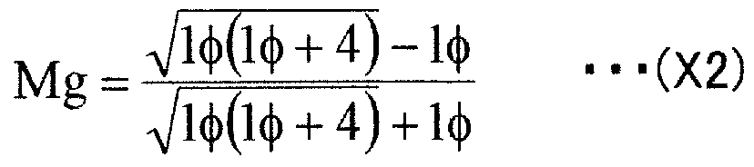
- the composite video generation unit 111 generates a composite video by synthesizing the background video with the attached video in accordance with an instruction from a controller (not shown). Based on the distance 1 between the monitor 101 and the background surface 1, the display size conversion unit 112 expands / contracts the background image or the composite image according to the conditional expression (X2) for determining the size (magnification) of the background image described later. ) The stretched background video or composite video is displayed on the monitor 101.
- the distance adjustment mechanism 105 is configured to make the parallax of the monitor image and the background BG force, which will be described later, substantially match based on the distance 1 between the monitor 101 and the background surface detected by the distance measuring means 103.
- the distance d between the monitor 101 and the optical lens 104 is adjusted according to the conditional expression (XI).
- FIG. 4 is a schematic diagram for explaining an example of an image that is visually recognized when the observer OBS observes the monitor 101.
- the virtual image of the monitor image is seamlessly connected to the background surface, and the observer OBS does not have the monitor 101. Only the video and character information synthesized by the processing means 106 can be observed so as to be superimposed on the background video.
- Conditional expression (XI) is an expression for determining the distance between the monitor 101 and the optical lens 104 so that the parallax from the monitor image and the background BG substantially matches as described above.
- “parallax coincides” means that the light power from a point on the background and the corresponding point on the monitor 101 reaches the observer OBS at the same angle regardless of the observation position of the observer OBS. Means that.
- the virtual image of the monitor image by the optical lens 104 coincides with the background surface. If the parallaxes are matched, the observer OBS cannot distinguish the light from the monitor 101 from the light generated by the background surface, so that the monitor image can be observed as displayed on the background surface. In this case, not only the parallax but also the convergence (the rotation angle of the crystalline lens) and the focus adjustment (the thickness of the crystalline lens) become equal.
- the point on the monitor 101 corresponding to one point P on the background surface is P ′.
- the observation position of the observer OBS is observation position 1
- the light rays from P and the light rays from P ' both arrive at an angle of 0 (horizontal force, etc.).
- the observation position of the observer OBS is the observation position 2
- the light beam from the point P on the background BG surface arrives at an angle u.
- the horizontal axis represents the distance l [m] between the monitor 101 and the background surface
- the vertical axis represents the distance d [m] between the motor 101 and the optical lens 104.
- the distance 1 between the monitor 101 and the background surface is relatively large, the distance d between the monitor 101 and the optical lens 104 is substantially constant.
- the distance adjusting mechanism 105 that adjusts the distance between the monitor 101 and the optical lens 104 is not necessarily required. .
- Conditional expression (X2) is an expression for determining the size (magnification) of the background video displayed on the monitor 101 as described above.
- the points on the monitor 101 corresponding to the two points P and Q on the background are P ′ and Q ′.
- ⁇ is the refractive power of the optical lens 104
- d is the distance between the monitor 101 and the optical lens 104
- z is the distance between the motor 101 and the observer OBS.
- Conditional Expression (XI) and Conditional Expression (X2) by satisfying the conditions of Conditional Expression (XI) and Conditional Expression (X2), by observing the monitor 101 through the optical lens 104, the background image reflected on the monitor 101 and the actual background BG can be seamlessly displayed. It becomes possible to observe.
- the monitor 101 may be seen directly without the optical lens 104 depending on the viewpoint position of the observer OBS. is there. This makes it impossible to observe the background BG video and the monitor video seamlessly. Therefore, conditional expressions (X3) and (X4) for preventing the monitor 101 from being seen directly without using the optical lens 104 will be described.
- FIG. 8 is an explanatory diagram for explaining the derivation of conditional expressions (X3) and (X4).
- r is the lens size when the optical lens 104 is measured in a direction (predetermined direction) from the optical axis in a plane parallel to the background surface, and m 0 is the same direction as the optical lens 104.
- the monitor size z and z, which also measure the optical axis force, are the expected distance between the observer OBS and the lens z on the system.
- conditional expression (X3) can be derived from the above expressions (2) and (3).
- Equation (X4) can be derived.
- FIG. 9 is an explanatory diagram for deriving a conditional expression for limiting the observation position of the observer OBS and a conditional expression for determining the lens characteristics based on the observation position restriction lens.
- r represents the optical lens 104 in a certain direction from the optical axis in a plane parallel to the background surface
- the lens size, ⁇ when measured in the (predetermined direction) indicates the observable range of the observer OBS in the axial direction perpendicular to the background surface.
- the distance ⁇ between the monitor 101 and the observer OBS can be expressed by the following equation (4) using paraxial theory as follows.
- R is a diagram showing the relationship.
- Figure 12 is a contour plot showing the maximum lens focal length, n max
- the horizontal axis indicates z and the vertical axis indicates ⁇ .
- the camera 102 that captures the background the monitor 101 that displays the captured background video, and the display surface side of the monitor 101 are provided. Since the virtual image of the monitor image by the optical lens 104 is substantially matched to the background surface of the monitor 101, the monitor image is displayed when the observer OBS views the monitor 101 through the optical lens 104. And the background BG can be visually recognized while maintaining continuity.
- the distance measuring means 103 for measuring the distance 1 between the monitor 101 and the background surface the distance adjusting mechanism 105 for adjusting the distance d between the optical lens 104 and the monitor 101
- the distance adjusting mechanism 105 adjusts the distance d between the monitor 101 and the optical lens 104 according to the conditional expression (XI) based on the distance 1 between the monitor 101 and the background surface measured by the distance measuring means 103. Therefore, the observer OBS cannot distinguish the light from the monitor 101 from the light emitted from the background surface, so that the monitor image can be observed as displayed on the background surface.
- the display size conversion unit 112 of the image processing unit 106 is set to 1 when the distance between the motor 101 and the background surface is 1 and the power of the optical lens 104 is ⁇ . Based on the distance 1 between the monitor 101 measured by the distance measuring means 103 and the background surface 1, the background image is scaled according to the above conditional expression (X2), so the observer OBS is displayed on the monitor 101.
- the background image size can be seen with the same size as the actual background BG.
- the size measured by the optical axis force in a certain direction of the monitor is m, the light
- the lens size r measured in a certain direction, such as the axis, is configured to satisfy the above conditional expression (X3), and the power ⁇ or focal length f of the optical lens 104 satisfies the above conditional expression (X4).
- the monitor 101 can be directly seen without passing through the optical lens 104, and the end M of the monitor 101 can be prevented from being seen through the optical lens 104.
- the composite video generation unit 111 of the image processing means 106 generates the composite video by synthesizing the additional video with the background video. It is possible to embody augmented reality as if observing the real world in daily life.
- FIG. 13 is an external configuration diagram of the video display system 200 according to the second embodiment.
- the camera 102 and the distance measuring unit 103 are integrated with the monitor 101, but it is not always necessary to integrate them.
- the video display system 200 according to the second embodiment has a configuration in which a camera 102 and a distance measuring unit 103 are arranged on a shield 201 existing between a monitor 101 and a background BG.
- the camera 102 is disposed at a position facing the background BG
- the distance measuring means 103 is disposed at a position facing the monitor 101.
- the distance measuring means 103 in order to measure the distance 1 between the monitor 101 and the background surface, the distance between the background surface and the shielding object 201 is fixed, and the distance between the shielding object 201 and the monitor 101 is measured.
- the distance between the shielding object 201 and the monitor 101 may be fixed, and the distance measuring means 103 may be installed on the power camera side to measure the distance between the background surface and the shielding object 201.
- the observer OBS can visually recognize the shielding object 201 so that it does not exist.
- the video display system 200 according to the second embodiment can be applied to, for example, an in-vehicle video display device.
- the pillar connecting the body of the moving body and the roof (usually a part expressed as a pillar) is used as a shield, a monitor is installed on the inner side of the pillar, and a camera is installed on the outer side of the vehicle.
- the force described as arranging the camera 102 for imaging the background BG between the monitor 101 and the background BG is particularly limited. Is not to be done. However, if the position of the camera 102 is significantly different from the position of the observer OBS, the background image captured by the camera 102 can be changed even if the parallax conditions and display magnification are adjusted using the above conditional expressions (XI) and (X2). Observer OBS's position force Seen Background BG is greatly different, making it difficult to observe seamlessly.
- FIG. 14 is a diagram showing an external configuration of video display system 300 according to Embodiment 3.
- a video display system 300 according to Embodiment 3 has a configuration in which a multi-eye mela 301 having 3 ⁇ 3 camera forces is disposed on the background surface side of the monitor 101. Note that the multi-eye melody 301 is not necessarily arranged on the monitor 101.
- FIG. 15 is a block configuration diagram of video display system 300 according to Embodiment 3.
- the multi-eye melody 301 captures a plurality of background images. Based on these multiple background images, Positional force of the observer A background image that should be visible is created, and the distance 1 between the monitor 101 and the background surface is measured using a stereo method or the like.
- the image processing means 302 includes a distance calculation unit 314 that calculates a distance 1 between the monitor 101 and the background surface using a stereo method or the like based on a plurality of background images captured by the multi-eye melody 301, Using the above-described arbitrary viewpoint image generation technology, the viewpoint position conversion image generation unit 311 that generates a background image that should be viewed based on a plurality of background images captured by the multi-eye melody 301 Based on the distance 1 between the monitor 101 and the background surface measured by the distance calculation unit 314 and the composite video generation unit 312 that synthesizes the additional video with the background video in accordance with instructions from the controller (not shown), the above conditional expression (X2) And a display size conversion unit 313 that expands and contracts the background video or the composite video.
- a distance calculation unit 314 that calculates a distance 1 between the monitor 101 and the background surface using a stereo method or the like based on a plurality of background images captured by the multi-eye melody 301.
- the background video or the synthesized video expanded and contracted by the display size conversion unit 313 is displayed on the monitor 101.
- the distance adjustment mechanism 105 adjusts the distance d between the monitor 101 and the optical lens 104 according to the conditional expression (XI) based on the distance 1 between the monitor 101 and the background surface measured by the distance calculation unit 314.
- a plurality of background images are captured by the multi-eye melody 301, and the viewpoint position conversion image generation unit 311 creates a background image of the observer viewpoint based on the plurality of background images. Therefore, the background image that should be visible from the observer's position can be displayed on the monitor 101 regardless of the position of the camera.
- the video display system and video display method according to the present invention are useful for video display devices in general, in-vehicle video display devices, and the like.
Landscapes
- Engineering & Computer Science (AREA)
- Multimedia (AREA)
- Signal Processing (AREA)
- Physics & Mathematics (AREA)
- General Physics & Mathematics (AREA)
- Optics & Photonics (AREA)
- Controls And Circuits For Display Device (AREA)
Abstract
Description


Claims

Priority Applications (2)
| Application Number | Priority Date | Filing Date | Title |
|---|---|---|---|
| US11/662,946 US7907200B2 (en) | 2004-09-15 | 2005-08-25 | Seamless image viewing system and method |
| JP2006535112A JP4417386B2 (ja) | 2004-09-15 | 2005-08-25 | 映像表示システムおよび映像表示方法 |
Applications Claiming Priority (2)
| Application Number | Priority Date | Filing Date | Title |
|---|---|---|---|
| JP2004-267738 | 2004-09-15 | ||
| JP2004267738 | 2004-09-15 |
Publications (1)
| Publication Number | Publication Date |
|---|---|
| WO2006030613A1 true WO2006030613A1 (ja) | 2006-03-23 |
Family
ID=36059869
Family Applications (1)
| Application Number | Title | Priority Date | Filing Date |
|---|---|---|---|
| PCT/JP2005/015476 Ceased WO2006030613A1 (ja) | 2004-09-15 | 2005-08-25 | 映像表示システムおよび映像表示方法 |
Country Status (3)
| Country | Link |
|---|---|
| US (1) | US7907200B2 (ja) |
| JP (1) | JP4417386B2 (ja) |
| WO (1) | WO2006030613A1 (ja) |
Cited By (5)
| Publication number | Priority date | Publication date | Assignee | Title |
|---|---|---|---|---|
| JP2008096868A (ja) * | 2006-10-16 | 2008-04-24 | Sony Corp | 撮像表示装置、撮像表示方法 |
| JP2011164184A (ja) * | 2010-02-05 | 2011-08-25 | Casio Computer Co Ltd | 画像表示装置、表示制御プログラム、及び画像表示システム |
| JP2014515854A (ja) * | 2011-03-29 | 2014-07-03 | クアルコム,インコーポレイテッド | 拡張現実システムにおける実世界表面への仮想画像のアンカリング |
| JP2020136947A (ja) * | 2019-02-21 | 2020-08-31 | いすゞ自動車株式会社 | 運転支援装置 |
| JP2020136948A (ja) * | 2019-02-21 | 2020-08-31 | いすゞ自動車株式会社 | 運転支援装置 |
Families Citing this family (13)
| Publication number | Priority date | Publication date | Assignee | Title |
|---|---|---|---|---|
| JP5158062B2 (ja) * | 2009-12-01 | 2013-03-06 | ブラザー工業株式会社 | ヘッドマウントディスプレイ |
| TW201331787A (zh) * | 2011-12-07 | 2013-08-01 | Microsoft Corp | 將虛擬資料顯示為列印的內容 |
| US9183807B2 (en) | 2011-12-07 | 2015-11-10 | Microsoft Technology Licensing, Llc | Displaying virtual data as printed content |
| US9229231B2 (en) | 2011-12-07 | 2016-01-05 | Microsoft Technology Licensing, Llc | Updating printed content with personalized virtual data |
| US9182815B2 (en) | 2011-12-07 | 2015-11-10 | Microsoft Technology Licensing, Llc | Making static printed content dynamic with virtual data |
| KR101332253B1 (ko) * | 2011-12-13 | 2013-12-02 | 현대자동차주식회사 | 사각지대를 발생시키지 않는 영상출력장치 |
| US9672796B2 (en) * | 2012-02-17 | 2017-06-06 | Lg Electronics Inc. | Electronic device including flexible display |
| US9165381B2 (en) | 2012-05-31 | 2015-10-20 | Microsoft Technology Licensing, Llc | Augmented books in a mixed reality environment |
| CN103605209A (zh) * | 2013-11-05 | 2014-02-26 | 中国科学技术大学 | 一种透射式立体显示眼镜装置 |
| TWI571655B (zh) * | 2014-08-22 | 2017-02-21 | 財團法人資訊工業策進會 | 顯示方法及顯示裝置 |
| KR102547821B1 (ko) * | 2016-11-25 | 2023-06-26 | 삼성전자주식회사 | 3d 디스플레이 장치 |
| JP7118650B2 (ja) * | 2018-01-18 | 2022-08-16 | キヤノン株式会社 | 表示装置 |
| US11899214B1 (en) | 2018-09-18 | 2024-02-13 | Apple Inc. | Head-mounted device with virtually shifted component locations using a double-folded light path |
Citations (5)
| Publication number | Priority date | Publication date | Assignee | Title |
|---|---|---|---|---|
| JPH0863089A (ja) * | 1994-08-19 | 1996-03-08 | Japan Radio Co Ltd | 頭部搭載型表示装置 |
| US5550585A (en) * | 1993-03-26 | 1996-08-27 | Allan Cherri | Video inter-view system |
| JP2001211403A (ja) * | 2000-01-25 | 2001-08-03 | Mixed Reality Systems Laboratory Inc | 頭部装着型表示装置及び頭部装着型表示システム |
| JP3092719U (ja) * | 2002-09-11 | 2003-03-28 | 英雄 堀田 | 車両用安全確認装置 |
| JP2004064131A (ja) * | 2002-07-24 | 2004-02-26 | Honda Motor Co Ltd | 車両用表示装置 |
Family Cites Families (5)
| Publication number | Priority date | Publication date | Assignee | Title |
|---|---|---|---|---|
| US5815411A (en) * | 1993-09-10 | 1998-09-29 | Criticom Corporation | Electro-optic vision system which exploits position and attitude |
| JP3338837B2 (ja) * | 1997-12-10 | 2002-10-28 | キヤノン株式会社 | 複合表示装置 |
| US6259470B1 (en) * | 1997-12-18 | 2001-07-10 | Intel Corporation | Image capture system having virtual camera |
| US6408257B1 (en) | 1999-08-31 | 2002-06-18 | Xerox Corporation | Augmented-reality display method and system |
| US6980363B1 (en) * | 1999-11-08 | 2005-12-27 | Canon Kabushiki Kaisha | Image observation apparatus and system |
-
2005
- 2005-08-25 US US11/662,946 patent/US7907200B2/en not_active Expired - Fee Related
- 2005-08-25 WO PCT/JP2005/015476 patent/WO2006030613A1/ja not_active Ceased
- 2005-08-25 JP JP2006535112A patent/JP4417386B2/ja not_active Expired - Fee Related
Patent Citations (5)
| Publication number | Priority date | Publication date | Assignee | Title |
|---|---|---|---|---|
| US5550585A (en) * | 1993-03-26 | 1996-08-27 | Allan Cherri | Video inter-view system |
| JPH0863089A (ja) * | 1994-08-19 | 1996-03-08 | Japan Radio Co Ltd | 頭部搭載型表示装置 |
| JP2001211403A (ja) * | 2000-01-25 | 2001-08-03 | Mixed Reality Systems Laboratory Inc | 頭部装着型表示装置及び頭部装着型表示システム |
| JP2004064131A (ja) * | 2002-07-24 | 2004-02-26 | Honda Motor Co Ltd | 車両用表示装置 |
| JP3092719U (ja) * | 2002-09-11 | 2003-03-28 | 英雄 堀田 | 車両用安全確認装置 |
Cited By (14)
| Publication number | Priority date | Publication date | Assignee | Title |
|---|---|---|---|---|
| US9665167B2 (en) | 2006-10-16 | 2017-05-30 | Sony Corporation | Imaging display apparatus and method |
| US9772686B2 (en) | 2006-10-16 | 2017-09-26 | Sony Corporation | Imaging display apparatus and method |
| US8253760B2 (en) | 2006-10-16 | 2012-08-28 | Sony Corporation | Imaging display apparatus and method |
| US8514149B2 (en) | 2006-10-16 | 2013-08-20 | Sony Corporation | Imaging display apparatus and method |
| US8624798B2 (en) | 2006-10-16 | 2014-01-07 | Sony Corporation | Imaging display apparatus and method |
| JP2008096868A (ja) * | 2006-10-16 | 2008-04-24 | Sony Corp | 撮像表示装置、撮像表示方法 |
| JP2011164184A (ja) * | 2010-02-05 | 2011-08-25 | Casio Computer Co Ltd | 画像表示装置、表示制御プログラム、及び画像表示システム |
| US9384594B2 (en) | 2011-03-29 | 2016-07-05 | Qualcomm Incorporated | Anchoring virtual images to real world surfaces in augmented reality systems |
| JP2014515854A (ja) * | 2011-03-29 | 2014-07-03 | クアルコム,インコーポレイテッド | 拡張現実システムにおける実世界表面への仮想画像のアンカリング |
| US9047698B2 (en) | 2011-03-29 | 2015-06-02 | Qualcomm Incorporated | System for the rendering of shared digital interfaces relative to each user's point of view |
| US9142062B2 (en) | 2011-03-29 | 2015-09-22 | Qualcomm Incorporated | Selective hand occlusion over virtual projections onto physical surfaces using skeletal tracking |
| JP2020136948A (ja) * | 2019-02-21 | 2020-08-31 | いすゞ自動車株式会社 | 運転支援装置 |
| JP2020136947A (ja) * | 2019-02-21 | 2020-08-31 | いすゞ自動車株式会社 | 運転支援装置 |
| JP7255230B2 (ja) | 2019-02-21 | 2023-04-11 | いすゞ自動車株式会社 | 運転支援装置 |
Also Published As
| Publication number | Publication date |
|---|---|
| JPWO2006030613A1 (ja) | 2008-07-31 |
| US20070285338A1 (en) | 2007-12-13 |
| JP4417386B2 (ja) | 2010-02-17 |
| US7907200B2 (en) | 2011-03-15 |
Similar Documents
| Publication | Publication Date | Title |
|---|---|---|
| JP4417386B2 (ja) | 映像表示システムおよび映像表示方法 | |
| JP7528344B2 (ja) | 仮想/拡張現実システムにおけるビーム角度センサ | |
| CN112424671B (zh) | 用于显示双目变形补偿的系统和方法 | |
| US11606548B2 (en) | Head mounted display device and method for providing visual aid using same | |
| JP7431267B2 (ja) | 虚像表示装置およびそれを用いたヘッドマウントディスプレイ | |
| US6222675B1 (en) | Area of interest head-mounted display using low resolution, wide angle; high resolution, narrow angle; and see-through views | |
| EP0702494B1 (en) | Three-dimensional image display apparatus | |
| US20100134495A1 (en) | Mixed reality presentation system and brightness adjustment method of virtual light source | |
| US9905143B1 (en) | Display apparatus and method of displaying using image renderers and optical combiners | |
| JPH10327433A (ja) | 合成画像の表示装置 | |
| JP2017204674A (ja) | 撮像装置、ヘッドマウントディスプレイ、情報処理システム、および情報処理方法 | |
| CN104076513A (zh) | 头戴式显示装置、头戴式显示装置的控制方法、以及显示系统 | |
| JPH08292394A (ja) | 頭部搭載型画像表示装置 | |
| JP2020511687A (ja) | ビデオシースルー型ディスプレイシステム | |
| JPH11102438A (ja) | 距離画像生成装置及び画像表示装置 | |
| JP2015060071A (ja) | 画像表示装置、画像表示方法、および画像表示プログラム | |
| JP2015231106A (ja) | ヘッドマウントディスプレイ装置及びヘッドマウントディスプレイシステム | |
| JP2011085830A (ja) | 映像表示システム | |
| JP2010181826A (ja) | 立体画像形成装置 | |
| KR20120066472A (ko) | 전방 물체를 이용한 증강 현실 출력 장치 및 방법 | |
| WO2011145311A1 (ja) | 表示装置および表示方法 | |
| CN115018942A (zh) | 用于车辆的图像显示的方法和设备 | |
| JP2019534493A (ja) | 拡張現実感のための装置および方法 | |
| CN105866948A (zh) | 在双目头戴设备上调节虚像投影距离及角度的方法 | |
| JP2011059435A (ja) | ヘッドマウントディスプレイ |
Legal Events
| Date | Code | Title | Description |
|---|---|---|---|
| AK | Designated states |
Kind code of ref document: A1 Designated state(s): AE AG AL AM AT AU AZ BA BB BG BR BW BY BZ CA CH CN CO CR CU CZ DE DK DM DZ EC EE EG ES FI GB GD GE GH GM HR HU ID IL IN IS JP KE KG KM KP KR KZ LC LK LR LS LT LU LV MA MD MG MK MN MW MX MZ NA NG NI NO NZ OM PG PH PL PT RO RU SC SD SE SG SK SL SM SY TJ TM TN TR TT TZ UA UG US UZ VC VN YU ZA ZM ZW |
|
| AL | Designated countries for regional patents |
Kind code of ref document: A1 Designated state(s): BW GH GM KE LS MW MZ NA SD SL SZ TZ UG ZM ZW AM AZ BY KG KZ MD RU TJ TM AT BE BG CH CY CZ DE DK EE ES FI FR GB GR HU IE IS IT LT LU LV MC NL PL PT RO SE SI SK TR BF BJ CF CG CI CM GA GN GQ GW ML MR NE SN TD TG |
|
| 121 | Ep: the epo has been informed by wipo that ep was designated in this application | ||
| DPE1 | Request for preliminary examination filed after expiration of 19th month from priority date (pct application filed from 20040101) | ||
| WWE | Wipo information: entry into national phase |
Ref document number: 2006535112 Country of ref document: JP |
|
| NENP | Non-entry into the national phase |
Ref country code: DE |
|
| WWE | Wipo information: entry into national phase |
Ref document number: 11662946 Country of ref document: US |
|
| 122 | Ep: pct application non-entry in european phase | ||
| WWP | Wipo information: published in national office |
Ref document number: 11662946 Country of ref document: US |