WO2005055543A1 - Channel estimation for ofdm systems - Google Patents

Channel estimation for ofdm systems Download PDF

Info

Publication number
WO2005055543A1
WO2005055543A1 PCT/AU2004/001704 AU2004001704W WO2005055543A1 WO 2005055543 A1 WO2005055543 A1 WO 2005055543A1 AU 2004001704 W AU2004001704 W AU 2004001704W WO 2005055543 A1 WO2005055543 A1 WO 2005055543A1
Authority
WO
WIPO (PCT)
Prior art keywords
matrix
sparse
smoothing
channel
row
Prior art date
Application number
PCT/AU2004/001704
Other languages
French (fr)
Inventor
Michael Faulkner
Igor Tolochko
Original Assignee
Australian Telecommunications Cooperative Research Centre
Priority date (The priority date is an assumption and is not a legal conclusion. Google has not performed a legal analysis and makes no representation as to the accuracy of the date listed.)
Filing date
Publication date
Priority claimed from AU2003906690A external-priority patent/AU2003906690A0/en
Application filed by Australian Telecommunications Cooperative Research Centre filed Critical Australian Telecommunications Cooperative Research Centre
Priority to US10/581,488 priority Critical patent/US20070110172A1/en
Publication of WO2005055543A1 publication Critical patent/WO2005055543A1/en

Links

Classifications

    • HELECTRICITY
    • H04ELECTRIC COMMUNICATION TECHNIQUE
    • H04LTRANSMISSION OF DIGITAL INFORMATION, e.g. TELEGRAPHIC COMMUNICATION
    • H04L25/00Baseband systems
    • H04L25/02Details ; arrangements for supplying electrical power along data transmission lines
    • H04L25/0202Channel estimation
    • H04L25/024Channel estimation channel estimation algorithms
    • H04L25/0242Channel estimation channel estimation algorithms using matrix methods
    • HELECTRICITY
    • H04ELECTRIC COMMUNICATION TECHNIQUE
    • H04LTRANSMISSION OF DIGITAL INFORMATION, e.g. TELEGRAPHIC COMMUNICATION
    • H04L25/00Baseband systems
    • H04L25/02Details ; arrangements for supplying electrical power along data transmission lines
    • H04L25/0202Channel estimation
    • H04L25/022Channel estimation of frequency response
    • HELECTRICITY
    • H04ELECTRIC COMMUNICATION TECHNIQUE
    • H04LTRANSMISSION OF DIGITAL INFORMATION, e.g. TELEGRAPHIC COMMUNICATION
    • H04L25/00Baseband systems
    • H04L25/02Details ; arrangements for supplying electrical power along data transmission lines
    • H04L25/0202Channel estimation
    • H04L25/0224Channel estimation using sounding signals
    • H04L25/0228Channel estimation using sounding signals with direct estimation from sounding signals
    • HELECTRICITY
    • H04ELECTRIC COMMUNICATION TECHNIQUE
    • H04LTRANSMISSION OF DIGITAL INFORMATION, e.g. TELEGRAPHIC COMMUNICATION
    • H04L27/00Modulated-carrier systems
    • H04L27/26Systems using multi-frequency codes
    • H04L27/2601Multicarrier modulation systems
    • H04L27/2647Arrangements specific to the receiver only

Definitions

  • the present invention relates generally to methods of channel estimation in wireless Orthogonal Frequency Division Multiplexing (OFDM) systems, and in particular to methods of channel estimation using Linear Minimum Means Square Error (LMMSE) estimation techniques.
  • OFDM Orthogonal Frequency Division Multiplexing
  • LMMSE Linear Minimum Means Square Error
  • OFDM Orthogonal Frequency Division Multiplexing
  • Transmitted diversity is an effective method to further improve wireless communication systems in fading environments.
  • space-time coded systems require accurate estimation of channel frequency responses.
  • LS estimators have low complexity, but suffer from a high Means Square Error (MSE), especially if the system operates with low signal to noise ratios.
  • MSE Means Square Error
  • MMSE estimators based on time-domain channel statistics, are highly complex and require significant numbers of multipliers and adders in any practical implementation. MMSE estimators provide good performance for sample spaced channel environments, but have limited performance for non-sample spaced channels and high signal to noise ratios. LMMSE estimators provide good performance for sample spaced and non- sample spaced channels.
  • LMMSE estimators suffer from being highly complex and require a large number of computations to be performed in order to achieve accurate channel estimation. It would be desirable to provide a method for performing channel estimation in an OFDM system with transmitter diversity that is simple and efficient, and minimises the computational complexity of existing channel estimation techniques. It would also be desirable to provide a method for performing channel estimation that alleviates or overcomes one or more problems of known channel estimation techniques.
  • One aspect of the present invention provides a method for performing linear channel estimation in an orthogonal frequency-division multiplexing system, the method including the steps of: receiving transmitted pilot symbols from a plurality of transmit antennas; forming a least-squares estimation matrix from the transmitted pilot symbols; forming a sparse smoothing matrix approximating a fixed weighting matrix, wherein each row vector in the sparse smoothing matrix contains one or more of the strongest weights in each row of the fixed weighting matrix; and deriving a channel estimation matrix from the sparse smoothing matrix and the least-squares estimation matrix.
  • the sparse smoothing matrix is defined according to:
  • E j (k) is the row energy of the sparse smoothing matrix with non-zero terms W j (k,m) formed from the M strongest weights of the k'th row of the fixed weighting matrix W j (k)
  • k represents the frequency bin number and j the transmitting antenna number.
  • the repeated pilot symbols may be preceded and/or followed by a cyclic prefix and may be transmitted on interleaved sub-carriers from the plurality of transmit antennas.
  • the independent pilot symbols may each be preceded and /or followed by a cyclic prefix, and may be transmitted on interleaved sub-carriers from the plurality of transmit antennas.
  • each pilot symbol may be preceded and/or followed by a cyclic prefix that is transmitted on interleaved sub-carriers from the plurality of transmit antennas.
  • a cyclic prefix window length or delay spread approximation length is chosen to enable the real and imaginary parts of the fixed weighting matrix to contain equal or zero entries.
  • the length of the cyclic prefix window or the delay spread approximation can be (l+N/2) or (l+N/4) where N is the length of the Inverse
  • the step of forming a sparse smoothing matrix includes: calculating a plurality of possible sparse smoothing matrices; storing the plurality of matrices in a storage device; and selectively retrieving one of the plurality of possible sparse smoothing matrices from the storage device.
  • the storage device may conveniently be a look-up table.
  • the smoothing matrix may be selected for retrieval from the storage device according to characteristics derived from the least squares estimation matrix.
  • the characteristics may include any one or more of the signal to noise ratio SNR, the root mean square delay spread of the power delay profile ⁇ rms and the delay spread of the power delay profiler x .
  • the method may further include the step of: making coefficients of the fixed weighting matrix real by performing a cyclic shift to locate the channel impulse response symmetrically around zero. Conveniently, cyclic shift may be performed in either the time domain or by an equivalent linear phase rotation in the frequency domain.
  • the method may further include the step of: using a symmetrically shaped delay spread approximation for the channel estimation. The delay spread approximation may be rectangular-shaped.
  • Another aspect of the invention provides a channel estimator for use in an orthogonal frequency-division multiplexing system, the channel estimator including: a least-squares estimation unit for forming a least-squares estimation matrix from pilot symbols transmitted from a plurality of transit antennas; a matrix formation unit for forming a sparse smoothing matrix approximating a fixed weighting matrix, wherein each row vector in the sparse smoothing matrix contains one or more of the strongest weights in each row of the fixed weighting matrix; and a channel estimation unit for forming a channel estimation matrix from the sparse smoothing matrix and the least-squares estimation matrix.
  • the matrix formation unit may include: a storage device for storing a plurality of possible sparse smoothing matrices; and a matrix selection unit for selectively retrieving one of the plurality of possible sparse smoothing matrices from the storage device.
  • the storage device may be a look-up table.
  • the matrix formation unit may act to select the sparse smoothing matrices for retrieval from the storage device according to characteristics derived from the least squares estimation matrix.
  • Figure 1 is schematic diagram of an OFDM system
  • Figure 2 is a schematic diagram of a channel estimator forming part of a receiver in the OFDM system of Figure 1
  • Figure 3 is a flow chart illustrating operation of the channel estimation of Figure 2
  • Figure 4 is a diagrammatic representation of three different pilot symbol allocation schemes for use in the channel estimation process shown in Figure 3
  • Figure 5 is a diagrammatic representation of the symmetrical location around zero of the channel impulse response and uniform delay spread approximation used in the LMMSE channel estimation shown in Figure 3
  • Figure 6 shows the mean squared error performance vs complexity of the SWC method compared to the SND method
  • Figure 7 shows the mean squared error performance vs S ⁇ R for the SND and SWC schemes.
  • FIG. 1 there is shown generally an OFDM based system 10 which exploits channel estimation and signal detection operations in equalisation.
  • a digital signal source 12 is protected by channel coding from a channel encoder 14 and is interleaved by an interleaver 16 against fading phenomenon. After this, the binary signal is modulated by an OFDM modulator 18 and transmitted over a multipath fading channel 20. During transmission, noise 22 is added. The sum signal is received at a receiver filter 24, which can take the form of a
  • the signal detector 26 DFT (Discrete Fourier Transform), and the output of the filter then passed to a signal detector 26. Due to the multipath channel transmission, some inter-symbol interference occurs in the received signal. Accordingly, the signal detector 26 requires knowledge of the Channel Impulse Response (CIR) characteristics in order to ensure successful removal of the inter-symbol interference.
  • CIR Channel Impulse Response
  • the channel impulse response characteristics are determined by a channel estimator 28. After detection, the signal is de-interleaved by a de-interleaver 30 and the channel decoded by a channel decoder 32 to extract the original message. Transmitter diversity is achieved in the OFDM system 10 shown in Figure 1 by the use of multiple transmit antennas.
  • pilot symbols are simultaneously sent from the multiple transmitter antennas on interleaved sub-carriers.
  • the LMMSE channel estimator 28 identifies channel characteristics in the non-measured sub channels by interpolating different sets of measured sub channels from each specified antenna.
  • the channel estimator 28 is a packet-type channel estimator, where only the frequency correlation of the channel is used in the channel estimation.
  • the frequency domain correlation depends on the multipath channel delay spread and can be described by a frequency domain correlation function rf k).
  • rf k For an exponentially decaying multipath power delay profile, the frequency domain correlation function rf(k) can be given by
  • ⁇ rms is the root-mean square (rms) delay spread of the power delay profile and Af denotes the sub-carrier spacing.
  • the LMMSE channel estimation vector H. corresponding to the f transmitter in a 2 x 1 diversity system can be obtained as follows:
  • I is the identity matrix and S ⁇ R is the expected value of S ⁇ R.
  • P j is the least-squares (LS) estimation vector of length K/2 at the pilot positions corresponding to antenna j, given by where X . is a diagonal matrix containing the transmitted pilot points xj(k) given by (1).
  • U and Vf are unitary matrices, and is the r x r upper left corner diagonal matrix, containing the strongest singular values.
  • the superscripts (.) r and (.) H denote rank-r and Hermitian transpose respectively.
  • the rank-r approaches a value of K/3, the low rank approximation no longer reduces the estimator complexity.
  • the channel estimator 28 provides an alternative sparse approximation of the fixed weighting matrix, namely LMMSE by significant weight catching (SWC).
  • SWC significant weight catching
  • the channel estimator 28 acts to restrict the frequency domain of the fixed weighting matrix W j to be a sparse (i.e only including limited number of non-zone elements) smoothing matrix containing the M strongest weights in each row, where M ⁇ K/2.
  • the sparse smoothing matrix approximating the fixed weighting matrix is obtained from:
  • W j (k) denotes a row vector from the fixed weighting matrix
  • FIG. 2 shows a practical implementation of the channel estimator 28.
  • a demultiplexer block 40 acts de-interleave pilot symbols into streams based on the transmit antenna from which the pilot symbols originated.
  • Least squared estimators 42 and 44 are based on known pilot data and receive the pilot symbol streams from the de-multiplexer block 40.
  • Inverse Fast Fourier Transform (IFFT) blocks 46 and 48 act to estimate the impulse response from which the route mean square delay spread (in blocks 50 and 52) and signal-to-noise ratio estimates (in blocks 54 and 56), together with other features, for example the absolute delay spread, are extracted.
  • IFFT Inverse Fast Fourier Transform
  • a common logic block 48 receives the signal-to-noise ratio estimates and route mean squared delay spread estimates and other features, and acts to select an appropriate sparse smoothing matrix from a lookup table stored in the non-volatile memory device 60.
  • Rotators 62 and 64 act to rotate the least squared estimates generated by blocks 42 and 44, which are then multiplied and summed with the sparse smoothing matrix identified by the common logic block 58, by means of the multiply and sum blocks 66 and 68.
  • the rotator block 62 and 64 perform a channel impulse response rotation in the frequency domain.
  • the multiply and sum blocks 66 and 68 act to smooth and interpolate the least squared estimates exploiting the significant weight catching technique of the present invention.
  • the rotating blocks 70 and 72 then act to de-rotate the output of the multiply and sum blocks 66 and 68 in order to generate the channel estimates. It should be noted that the de-rotation blocks 70 and 72 can be avoided if the data is pre-rotated.
  • the steps carried out by the channel estimator are depicted in Figure 3. This figure shows that initially, at step 80, transmitted pilot symbols are received from the multiple transmit antennas used in the OFDM system with transmitted diversity shown in Figure 1.
  • the LMMSE channel estimation effector ⁇ can be obtained from the product of a sparse smoothing matrix and the least squares estimation.
  • a number of possible sparse smoothing matrices may be calculated and stored in a lookup table within the channel estimator 28 beforehand.
  • a channel impulse response is initially obtained by performing an Inverse Fast Fourier Transform (IFFT) operation at step 84 on the least squares estimation matrix.
  • IFFT Inverse Fast Fourier Transform
  • the signal to noise ratio From the Inverse Fast Fourier Transform, the mean square delay spread of the power delay profile and delay spread of the received pilot symbols are firstly calculated.
  • the power delay profile is the output of the IFFT and it is confined to the length of the cyclic prefix.
  • a noise estimate can be taken from the other outputs to form an SNR estimate.
  • the time between the first and last significant multipath component of the power delay profile is the delay spread and the rms delay spread can be obtained from:
  • the most appropriate interpolation or sparse smoothing matrices is then selected by the channel estimator 28 from a lookup table, at step 88.
  • the LMMSE channel estimation is carried out by computing the product of the sparse smoothing matrix selected by the channel estimator at step 58 and the least squares estimation matrix as determined in step 82.
  • WLANs Broadband Wireless Local Area Networks
  • the pilot symbols are preceded by a double length Cyclic Prefix (CP) to effectively eliminate inter-symbol interference and inter-carrier interference due to a fading channel.
  • CP Cyclic Prefix
  • the following modified pilot schemes that enable the inclusion of transmitter diversity or multiple input multiple output systems within existing OFDM standards have been found to be particularly suitable for use with the present invention.
  • the first scheme shown in Figure 4(a) consists of a standard pilot system in which two repeated (in this case long) pilot symbols 190 and 102 are preceded with a cyclic prefix 104.
  • the cyclic prefix is a double length cyclic prefix of 1600 ns.
  • the second scheme shown in Figure 4(b) splits the two repeated pilot symbols into two independent pilot symbols 106 and 108, each of which is preceded with a cyclic prefix, in this case a single cyclic prefix of length 800 ns.
  • the cyclic prefix preceding the pilot symbol 106 is referenced 110 in Figure 4, whilst the cyclic prefix preceding the pilot symbol 108 is referenced 112.
  • the third scheme shown in Figure 4(c) transmits a single pilot symbol 114 preceded by a cyclic prefix, in this case a double length cyclic prefix length of 1600 ns referenced 116 over twice the number of sub channels but half the bandwidth of the two previously mentioned schemes.
  • the three exemplary schemes shown in Figure 4 are 4x1 antenna diversity system.
  • the least squares estimation matrix P j of the two repetitive OFDM symbols in the first pilot scheme, shown in Figure 4(a) can be obtained in step 82 as follows
  • the least P. squares estimation matrix in the second pilot scheme shown in Figure 4(b) , can be obtained in step 62 by:
  • P. (i) is the LS estimates vector of length K/Q, corresponding to the z ' th received pilot OFDM symbol from transmitter j, given by:
  • Channel estimator complexity can be further reduced (where the exponential power delay profile of the channel can be approximated as uniform), if the length of the uniform power delay profile is chosen correctly reduced complexity weighting coefficients result.
  • the length of the power delay profile is usually set to the cyclic prefix length. "Good" Cyclic Prefix (CP) length windows are (l+N/2) or (l+N/4), where N is the length of the IDFT used to form the OFDM symbol. In this way the real and imaginary parts of the fixed weighting matrix values are made to contain equal or zero entries when "good" cyclic prefix length windows are chosen.
  • FIG. 5 shows a typical channel impulse response 120.
  • a uniform (rectangular) shaped power delay profile 122 is drawn encompassing the impulse response.
  • Figure 5 (bottom) shows both the channel impulse response and the assumed uniform power delay profile shifted to the left and therefore centering this power delay profile about zero. This is achieved by a cyclic shift when used with DFT/TDFT block processing, as used by OFDM systems.
  • the sequence of steps carried out by the channel estimator 28 in order to provide the LMMSE channel estimation by significant weight catching may optionally include the steps of performing, at step 92, a phase rotation of the least squares estimation matrix derived in step 82, and a complimentary step 94 of performing a de-rotation of the LMMSE channel estimates derived in step 90.
  • the channel estimation vectors are provided to the detector 26 in step 96.
  • the cyclic shift for the channel impulse response can be achieved in the frequency domain by applying a linear phase rotation across the LS frequency estimates of (-2 ⁇ kp/N), where the shift, p, is half the length of the uniform power delay profile.
  • Note p is negative for the complementary step of 94.
  • the latter step can be avoided if the data symbols are pre-rotated. If the "good" cyclic prefix windows are used, steps 92 and 94 may not be required. However, this approach can reduce the results provided by the channel estimator 28 due to a less than optimal windowing of the channel impulse response.
  • MSE mean squared error
  • the MSE channel estimation performance was evaluated by transmitting two long OFDM-BPSK pilot symbols through a fading multipath channel 1000 times. For each iteration, the pilot symbols were simultaneously sent from the two transmit antennas on interleaved sub-carriers.
  • the LMMSE by SWC is a better compromise in performance versus complexity, as shown in Figure 6.
  • the LMMSE by SWC requires only 12 complex multipliers in order to reach an adequate performance in channel B and the estimator complexity is reduced by more than 50% compared to the full LMMSE.
  • the performance of the simplified LMMSE algorithm remains almost unchanged in all the channels, especially for the low number of complex multipliers ( ⁇ 12).
  • the MSE in channel B is presented in Figure 7.
  • the number of complex multipliers M 3r/2 in the sparse approximations was set to the fixed nominal values of 12 and 21.

Abstract

A method for performing channel estimation in an orthogonal frequency-division multiplexing system, the method including the steps of: receiving (80) transmitting pilot symbols from a plurality of transmit antennas; forming (82) a least-squares estimation matrix from the transmitted pilot symbols; forming (84-88) a sparse smoothing matrix approximating a fixed weighting matrix, wherein each row vector in the sparse smoothing matrix contains one or more of the strongest weights in each row of the fixed weighting matrix; and (90) deriving a channel estimation matrix from the sparse smoothing matrix and the least-squares estimation matrix.

Description

CHANNEL ESTIMATION FOR OFDM SYSTEMS
The present invention relates generally to methods of channel estimation in wireless Orthogonal Frequency Division Multiplexing (OFDM) systems, and in particular to methods of channel estimation using Linear Minimum Means Square Error (LMMSE) estimation techniques. Orthogonal Frequency Division Multiplexing (OFDM) is a high spectral efficiency type of multi-carrier modulation system, which has many advantages of single carrier systems, especially for high data rate transmission in time dispersive channels. Transmitted diversity is an effective method to further improve wireless communication systems in fading environments. Space-time coded OFDM systems with transmitter diversity capable of reliable high data rate wireless communications promise to be an effective alternative for broadband wireless services. However, space-time coded systems require accurate estimation of channel frequency responses. Traditional one-dimensional channel estimation techniques for OFDM systems include (a) Leased Squares (LS), (b) Minimum Means Square Error (MMSE) and (c) Linear Minimum Means Squared Error (LMMSE) estimation techniques. LS estimators have low complexity, but suffer from a high Means Square Error (MSE), especially if the system operates with low signal to noise ratios. On the other hand, MMSE estimators, based on time-domain channel statistics, are highly complex and require significant numbers of multipliers and adders in any practical implementation. MMSE estimators provide good performance for sample spaced channel environments, but have limited performance for non-sample spaced channels and high signal to noise ratios. LMMSE estimators provide good performance for sample spaced and non- sample spaced channels. Nevertheless, practical implementations of LMMSE estimators suffer from being highly complex and require a large number of computations to be performed in order to achieve accurate channel estimation. It would be desirable to provide a method for performing channel estimation in an OFDM system with transmitter diversity that is simple and efficient, and minimises the computational complexity of existing channel estimation techniques. It would also be desirable to provide a method for performing channel estimation that alleviates or overcomes one or more problems of known channel estimation techniques. One aspect of the present invention provides a method for performing linear channel estimation in an orthogonal frequency-division multiplexing system, the method including the steps of: receiving transmitted pilot symbols from a plurality of transmit antennas; forming a least-squares estimation matrix from the transmitted pilot symbols; forming a sparse smoothing matrix approximating a fixed weighting matrix, wherein each row vector in the sparse smoothing matrix contains one or more of the strongest weights in each row of the fixed weighting matrix; and deriving a channel estimation matrix from the sparse smoothing matrix and the least-squares estimation matrix. In one embodiment the sparse smoothing matrix is defined according to:
Figure imgf000004_0001
where Ej (k) is the row energy of the sparse smoothing matrix with non-zero terms Wj(k,m) formed from the M strongest weights of the k'th row of the fixed weighting matrix Wj(k), k represents the frequency bin number and j the transmitting antenna number. The repeated pilot symbols may be preceded and/or followed by a cyclic prefix and may be transmitted on interleaved sub-carriers from the plurality of transmit antennas.
Alternatively, the independent pilot symbols, may each be preceded and /or followed by a cyclic prefix, and may be transmitted on interleaved sub-carriers from the plurality of transmit antennas.
In another alternative, each pilot symbol may be preceded and/or followed by a cyclic prefix that is transmitted on interleaved sub-carriers from the plurality of transmit antennas.
Preferably, a cyclic prefix window length or delay spread approximation length is chosen to enable the real and imaginary parts of the fixed weighting matrix to contain equal or zero entries. The length of the cyclic prefix window or the delay spread approximation can be (l+N/2) or (l+N/4) where N is the length of the Inverse
Discrete Fourier Transform used to form the pilot symbol.
In a preferred arrangement the step of forming a sparse smoothing matrix includes: calculating a plurality of possible sparse smoothing matrices; storing the plurality of matrices in a storage device; and selectively retrieving one of the plurality of possible sparse smoothing matrices from the storage device.
The storage device may conveniently be a look-up table. The smoothing matrix may be selected for retrieval from the storage device according to characteristics derived from the least squares estimation matrix.
The characteristics may include any one or more of the signal to noise ratio SNR, the root mean square delay spread of the power delay profile τrms and the delay spread of the power delay profiler x. The method may further include the step of: making coefficients of the fixed weighting matrix real by performing a cyclic shift to locate the channel impulse response symmetrically around zero. Conveniently, cyclic shift may be performed in either the time domain or by an equivalent linear phase rotation in the frequency domain. The method may further include the step of: using a symmetrically shaped delay spread approximation for the channel estimation. The delay spread approximation may be rectangular-shaped.
Another aspect of the invention provides a channel estimator for use in an orthogonal frequency-division multiplexing system, the channel estimator including: a least-squares estimation unit for forming a least-squares estimation matrix from pilot symbols transmitted from a plurality of transit antennas; a matrix formation unit for forming a sparse smoothing matrix approximating a fixed weighting matrix, wherein each row vector in the sparse smoothing matrix contains one or more of the strongest weights in each row of the fixed weighting matrix; and a channel estimation unit for forming a channel estimation matrix from the sparse smoothing matrix and the least-squares estimation matrix. Conveniently, the matrix formation unit may include: a storage device for storing a plurality of possible sparse smoothing matrices; and a matrix selection unit for selectively retrieving one of the plurality of possible sparse smoothing matrices from the storage device.
The storage device may be a look-up table.
The matrix formation unit may act to select the sparse smoothing matrices for retrieval from the storage device according to characteristics derived from the least squares estimation matrix.
In order to assist in arriving at an understanding of the present invention, a preferred embodiment is illustrated in the attached drawings. However, it should be understood that the following description is illustrative only and should not be taken in any way as a restriction on the generality of the invention as described here above. In the drawings: Figure 1 is schematic diagram of an OFDM system; Figure 2 is a schematic diagram of a channel estimator forming part of a receiver in the OFDM system of Figure 1; Figure 3 is a flow chart illustrating operation of the channel estimation of Figure 2; Figure 4 is a diagrammatic representation of three different pilot symbol allocation schemes for use in the channel estimation process shown in Figure 3; Figure 5 is a diagrammatic representation of the symmetrical location around zero of the channel impulse response and uniform delay spread approximation used in the LMMSE channel estimation shown in Figure 3; Figure 6 shows the mean squared error performance vs complexity of the SWC method compared to the SND method; and Figure 7 shows the mean squared error performance vs SΝR for the SND and SWC schemes. Referring now to Figure 1, there is shown generally an OFDM based system 10 which exploits channel estimation and signal detection operations in equalisation. A digital signal source 12 is protected by channel coding from a channel encoder 14 and is interleaved by an interleaver 16 against fading phenomenon. After this, the binary signal is modulated by an OFDM modulator 18 and transmitted over a multipath fading channel 20. During transmission, noise 22 is added. The sum signal is received at a receiver filter 24, which can take the form of a
DFT (Discrete Fourier Transform), and the output of the filter then passed to a signal detector 26. Due to the multipath channel transmission, some inter-symbol interference occurs in the received signal. Accordingly, the signal detector 26 requires knowledge of the Channel Impulse Response (CIR) characteristics in order to ensure successful removal of the inter-symbol interference. The channel impulse response characteristics are determined by a channel estimator 28. After detection, the signal is de-interleaved by a de-interleaver 30 and the channel decoded by a channel decoder 32 to extract the original message. Transmitter diversity is achieved in the OFDM system 10 shown in Figure 1 by the use of multiple transmit antennas. To enable channel estimation, pilot symbols are simultaneously sent from the multiple transmitter antennas on interleaved sub-carriers. At the receiver end, the LMMSE channel estimator 28 identifies channel characteristics in the non-measured sub channels by interpolating different sets of measured sub channels from each specified antenna. In a downlink diversity environment with two transmit antennas and one receiver, the two transmit antennas j = 1, 2 simultaneously send to OFDM pilot symbols on K interleaved sub-carriers. The pilot symbols X, and X2 are defined as follows: xl = {ao, 0, ai, 0, a2, ..., aκ/2-1, 0} x2 = {0, b0, 0, b1, 0, b2, ..., 0, bκ/2-1} (1) where α& and bk are arbitrary complex numbers with magnitude of 1. Each of these signal forms an OFDM block. With the channel impulse response confined to a cyclic prefix (CP) length, the Digital Fourier Transform (DFT) of the received symbols can be given by y(k) = jHJ(k)xj(k) + v(k) (2)
where k = 0, 1, ..., K - 1 denotes the sub-carrier number, H J) is the channel frequency response corresponding to transmit antenna j and v(k) is the additive complex Gaussian noise with zero mean and variance one. In this exemplary embodiment, the channel estimator 28 is a packet-type channel estimator, where only the frequency correlation of the channel is used in the channel estimation. The frequency domain correlation depends on the multipath channel delay spread and can be described by a frequency domain correlation function rf k). For an exponentially decaying multipath power delay profile, the frequency domain correlation function rf(k) can be given by
^ + j2πτrmsk( f)
where τrms is the root-mean square (rms) delay spread of the power delay profile and Af denotes the sub-carrier spacing. The LMMSE channel estimation vector H. corresponding to the f transmitter in a 2 x 1 diversity system can be obtained as follows:
Figure imgf000009_0001
where R„ s = RH P and R= ε = R Po Pn + - -/ are the correlation matrices of size K x J ' O SINVJRK. J
K/2 and K/2 x K/2 respectively [3]. I is the identity matrix and SΝR is the expected value of SΝR. Pj is the least-squares (LS) estimation vector of length K/2 at the pilot positions corresponding to antenna j, given by
Figure imgf000009_0002
where X . is a diagonal matrix containing the transmitted pilot points xj(k) given by (1).
The best low-rank approximation of RH p R~ ~ R~ ~ is given by Singular Value
Decomposition (SND). Then, with the appropriate substitutions in (4), the rank- r estimator is defined by
Figure imgf000009_0003
where U and Vf are unitary matrices, and is the r x r upper left corner diagonal matrix, containing the strongest singular values. The superscripts (.)r and (.) H denote rank-r and Hermitian transpose respectively. In channels with large delay spreads, the rank-r approaches a value of K/3, the low rank approximation no longer reduces the estimator complexity. The channel estimator 28 provides an alternative sparse approximation of the fixed weighting matrix, namely LMMSE by significant weight catching (SWC). For notional convenience, the equation (4) can be rewritten.
Figure imgf000009_0004
where TV, = R„ = R~ ~ is the fixed weighting matrix (otherwise known as the 
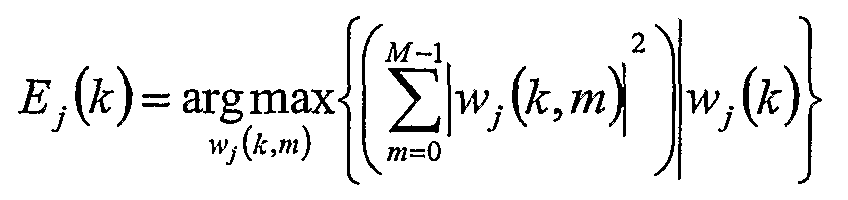
J nAι ^A interpolation matrix). Some row entries of the W- contain stronger weights than the others, with the strongest values on its diagonal. The channel estimator 28 acts to restrict the frequency domain of the fixed weighting matrix Wj to be a sparse (i.e only including limited number of non-zone elements) smoothing matrix containing the M strongest weights in each row, where M ≤K/2. The sparse smoothing matrix approximating the fixed weighting matrix is obtained from:
Figure imgf000010_0001
where Wj(k) denotes a row vector from the fixed weighting matrix.
Figure 2 shows a practical implementation of the channel estimator 28. A demultiplexer block 40 acts de-interleave pilot symbols into streams based on the transmit antenna from which the pilot symbols originated. Least squared estimators 42 and 44 are based on known pilot data and receive the pilot symbol streams from the de-multiplexer block 40. Inverse Fast Fourier Transform (IFFT) blocks 46 and 48 act to estimate the impulse response from which the route mean square delay spread (in blocks 50 and 52) and signal-to-noise ratio estimates (in blocks 54 and 56), together with other features, for example the absolute delay spread, are extracted. A common logic block 48 receives the signal-to-noise ratio estimates and route mean squared delay spread estimates and other features, and acts to select an appropriate sparse smoothing matrix from a lookup table stored in the non-volatile memory device 60. Rotators 62 and 64 act to rotate the least squared estimates generated by blocks 42 and 44, which are then multiplied and summed with the sparse smoothing matrix identified by the common logic block 58, by means of the multiply and sum blocks 66 and 68. The rotator block 62 and 64 perform a channel impulse response rotation in the frequency domain. The multiply and sum blocks 66 and 68 act to smooth and interpolate the least squared estimates exploiting the significant weight catching technique of the present invention. The rotating blocks 70 and 72 then act to de-rotate the output of the multiply and sum blocks 66 and 68 in order to generate the channel estimates. It should be noted that the de-rotation blocks 70 and 72 can be avoided if the data is pre-rotated. The steps carried out by the channel estimator are depicted in Figure 3. This figure shows that initially, at step 80, transmitted pilot symbols are received from the multiple transmit antennas used in the OFDM system with transmitted diversity shown in Figure 1. At step 82, the least squares estimation matrix Pj is computed by the channel estimator 28 according to the expression Pj = X^yj . The LMMSE channel estimation effector } can be obtained from the product of a sparse smoothing matrix and the least squares estimation. In order to further minimise channel estimator complexity and improve the estimation accuracy of the channel estimator 28, a number of possible sparse smoothing matrices may be calculated and stored in a lookup table within the channel estimator 28 beforehand. In order for this to occur, a channel impulse response is initially obtained by performing an Inverse Fast Fourier Transform (IFFT) operation at step 84 on the least squares estimation matrix. From the Inverse Fast Fourier Transform, the signal to noise ratio, the mean square delay spread of the power delay profile and delay spread of the received pilot symbols are firstly calculated. The power delay profile is the output of the IFFT and it is confined to the length of the cyclic prefix. A noise estimate can be taken from the other outputs to form an SNR estimate. The time between the first and last significant multipath component of the power delay profile is the delay spread and the rms delay spread can be obtained from:
Figure imgf000011_0001
where the al is the amplitude and τt is the delay of the i'th multipath component.
With the knowledge of the aforementioned channel impulse response characteristics having been estimated at step 86, the most appropriate interpolation or sparse smoothing matrices is then selected by the channel estimator 28 from a lookup table, at step 88. At step 90, the LMMSE channel estimation is carried out by computing the product of the sparse smoothing matrix selected by the channel estimator at step 58 and the least squares estimation matrix as determined in step 82. Broadband Wireless Local Area Networks (WLANs) incorporate two long OFDM pilot symbols at the beginning of a data packet, to enable channel estimation. The pilot symbols are preceded by a double length Cyclic Prefix (CP) to effectively eliminate inter-symbol interference and inter-carrier interference due to a fading channel. The following modified pilot schemes that enable the inclusion of transmitter diversity or multiple input multiple output systems within existing OFDM standards have been found to be particularly suitable for use with the present invention. The first scheme, shown in Figure 4(a) consists of a standard pilot system in which two repeated (in this case long) pilot symbols 190 and 102 are preceded with a cyclic prefix 104. In this case, the cyclic prefix is a double length cyclic prefix of 1600 ns. The second scheme, shown in Figure 4(b) splits the two repeated pilot symbols into two independent pilot symbols 106 and 108, each of which is preceded with a cyclic prefix, in this case a single cyclic prefix of length 800 ns. The cyclic prefix preceding the pilot symbol 106 is referenced 110 in Figure 4, whilst the cyclic prefix preceding the pilot symbol 108 is referenced 112. The third scheme shown in Figure 4(c) transmits a single pilot symbol 114 preceded by a cyclic prefix, in this case a double length cyclic prefix length of 1600 ns referenced 116 over twice the number of sub channels but half the bandwidth of the two previously mentioned schemes. The three exemplary schemes shown in Figure 4 are 4x1 antenna diversity system. The first two schemes form two consecutive OFDM pilot symbols xj (i), i = (0, 1) for each antennay = (1, 2, ..., 4). The third scheme forms only one pilot symbol xj (i), i = 0 for each antennaj. All three schemes have a preamble length of 8 μs. In channels with a limited mobility, the least squares estimation matrix Pj of the two repetitive OFDM symbols in the first pilot scheme, shown in Figure 4(a) can be obtained in step 82 as follows:
Pj = x?∑ ι=0 y (9)
where X} = Xj (i), i = (0,1) is a diagonal matrix of size K/Q x K/Q containing the transmitted pilot points Xj (k).
The least P. squares estimation matrix in the second pilot scheme, shown in Figure 4(b) , can be obtained in step 62 by:
P = ζ.(θ) ζ.(l) (10)
where P. (i) is the LS estimates vector of length K/Q, corresponding to the z'th received pilot OFDM symbol from transmitter j, given by:
Figure imgf000013_0001
Equation (11) also represents the LS estimation vector P. = Pj (i), i = 0 of length 2K/Q for the third pilot scheme shown in Figure 4(c). With 2K sub-carriers, this scheme requires a twofold increase for the correlation matrix size and FFT lengths, when calculating H . and y j) respectively.
Channel estimator complexity can be further reduced (where the exponential power delay profile of the channel can be approximated as uniform), if the length of the uniform power delay profile is chosen correctly reduced complexity weighting coefficients result. The length of the power delay profile is usually set to the cyclic prefix length. "Good" Cyclic Prefix (CP) length windows are (l+N/2) or (l+N/4), where N is the length of the IDFT used to form the OFDM symbol. In this way the real and imaginary parts of the fixed weighting matrix values are made to contain equal or zero entries when "good" cyclic prefix length windows are chosen. With a uniform power delay profile, coefficients of the fixed weighting matrix can be made real if the Channel Impulse Response (CIR) is located symmetrically around zero by performing a cyclic shift, as shown in Figure 5. This approach makes all the coefficients of the fixed weighting matrix real, thus reducing the complexity of the computations required to be performed by the channel estimator 28. Figure 5 (top) shows a typical channel impulse response 120. A uniform (rectangular) shaped power delay profile 122 is drawn encompassing the impulse response. Figure 5 (bottom) shows both the channel impulse response and the assumed uniform power delay profile shifted to the left and therefore centering this power delay profile about zero. This is achieved by a cyclic shift when used with DFT/TDFT block processing, as used by OFDM systems. The negative time components appear at the end of the block as shown in Figure 5 (bottom). Returning once again to Figure 3, the sequence of steps carried out by the channel estimator 28 in order to provide the LMMSE channel estimation by significant weight catching may optionally include the steps of performing, at step 92, a phase rotation of the least squares estimation matrix derived in step 82, and a complimentary step 94 of performing a de-rotation of the LMMSE channel estimates derived in step 90. Finally, the channel estimation vectors are provided to the detector 26 in step 96. The cyclic shift for the channel impulse response can be achieved in the frequency domain by applying a linear phase rotation across the LS frequency estimates of (-2πkp/N), where the shift, p, is half the length of the uniform power delay profile. Note p is negative for the complementary step of 94. The latter step can be avoided if the data symbols are pre-rotated. If the "good" cyclic prefix windows are used, steps 92 and 94 may not be required. However, this approach can reduce the results provided by the channel estimator 28 due to a less than optimal windowing of the channel impulse response.
The Applicants have carried out simulations in an 802.11a system with 2 transmitters and 1 receiver. The mean squared error (MSE) for antenna y is given by:
Figure imgf000014_0001
The system operated in an indoor HIPERLAN/2 non-sample-spaced channels A (τms = 50 ns), B (τms = 100 ns) and C (τrms = 150 ns), with the total transmit power normalized to unity. It was assumed that perfect knowledge of the SNR and τ rmS were available for calculation of the Wj . The MSE channel estimation performance was evaluated by transmitting two long OFDM-BPSK pilot symbols through a fading multipath channel 1000 times. For each iteration, the pilot symbols were simultaneously sent from the two transmit antennas on interleaved sub-carriers. The duration of the two long pilots was 8 μs including double length CP of 1.6 μs and the total system bandwidth was subdivided into K = 52 sub-carriers (out of a possible 64). For the sparse approximations, the number of complex multipliers (M < K/2) was chosen to give targeted MSE error floor <_- 25 dB. It was observed that the LMMSE by Single Value Decomposition (SND) outperforms the LMMSE by Significant Weight Catching (SWC) in channel A, when the rank r <8 as can be seen in Figure 6. At a fixed value of SΝR = 25 dB, its MSE error floor is well below of 25 dB and the estimator requires 12 complex multipliers. However, if the channel's delay spread is increased (channels B and C), the LMMSE by SWC is a better compromise in performance versus complexity, as shown in Figure 6. The LMMSE by SWC requires only 12 complex multipliers in order to reach an adequate performance in channel B and the estimator complexity is reduced by more than 50% compared to the full LMMSE. It should also be noted that the performance of the simplified LMMSE algorithm remains almost unchanged in all the channels, especially for the low number of complex multipliers (≤12). To illustrate the performance for a dynamic SΝR range, the MSE in channel B is presented in Figure 7. The number of complex multipliers M = 3r/2 in the sparse approximations was set to the fixed nominal values of 12 and 21. With the MSE gain of 9 dB over the LMMSE by SND for M = 12 at SΝR = 30 dB, it can be seen that the LMMSE by SWC is the better choice for a reduced complexity LMMSE channel estimator. From the foregoing, it is apparent that LMMSE by SWC estimation technique described above can reduce computational complexity of the traditional LMMSE channel estimator by more than 50% and it outperforms the LMMSE by SND when channel delay spreads exceeding 50 ns. Finally, it is to be understood that various modifications and/or additions may be made to the above described method of channel estimation without departing from the ambit of the present invention as defined in the claims appended hereto.

Claims

CLAIMS:
1. A method for performing channel estimation in an orthogonal frequency- division multiplexing system, the method including the steps of: receiving transmitted pilot symbols from a plurality of transmit antennas; forming a least-squares estimation matrix from the transmitted pilot symbols; forming a sparse smoothing matrix approximating a fixed weighting matrix, wherein each row vector in the sparse smoothing matrix contains one or more of the strongest weights in each row of the fixed weighting matrix; and deriving a channel estimation matrix from the sparse smoothing matrix and the least-squares estimation matrix.
2. A method according to claim 1, wherein the sparse smoothing matrix is defined according to:
Figure imgf000017_0001
where E7(&) is the row of the sparse smoothing matrix with non-zero terms w.(k,m) formed from the M strongest weights of the k'th row of the fixed weighting matrix Wj (k) ; k represents the frequency bin number and j the transmitting antenna number.
3. A method according to either one of claims 1 or 2, wherein repeated pilot symbols preceded and/or followed by a cyclic prefix are transmitted on interleaved sub-carriers from the plurality of transmit antennas.
4. A method according to either one of claims 1 or 2, wherein independent pilot symbols, each preceded and/or followed by a cyclic prefix, are transmitted on interleaved sub-carriers from the plurality of transmit antennas.
5. A method according to either one of claims 1 or 2, wherein a pilot symbol preceded and/or followed by a cyclic prefix is transmitted on interleaved sub-carriers from the plurality of transmit antennas.
6. A method according to any one of the preceding claims, and further including the step of: selecting a cyclic prefix window length or delay spread approximation length to enable real and imaginary parts of the fixed weighting matrix to contain equal or zero entries.
7. A method according to claim 6, wherein the length of the cyclic prefix window or the delay spread approximation is (l+N/2) or (l+N/4), where N is the length of the Inverse Discrete Fourier Transform used to form the pilot symbol.
8. A method according to any one of the preceding claims, wherein the step of forming a sparse smoothing matrix includes: calculating a plurality of possible sparse smoothing matrices; storing the plurality of matrices in a storage device; and selectively retrieving one of the plurality of possible sparse smoothing matrices from the storage device.
9. A method according to claim 8, wherein the storage device is a look-up table.
10. A method according to either one of claims 8 or 9, wherein the smoothing matrix is selected for retrieval from the storage device according to characteristics derived from the least squares estimation matrix.
11. A method according to claim 10, wherein the characteristics include any one or more of the signal to noise ratio SNR, the root mean square delay spread of the power delay profile τrm and the delay spread of the power delay profile τ x.
12. A method according to any one of the preceding claims, and further including the step of: making coefficients of the fixed weighting matrix real by performing a cyclic shift to locate the channel impulse response symmetrically around zero.
13. A method according to claim 12, wherein the cyclic shift is performed in either the time domain or by an equivalent linear phase rotation in the frequency domain..
14. A method according to any one of the preceding claims, and further including the step of: using a symmetrically shaped delay spread approximation for the channel estimation.
15. A method according to claim 14, wherein the delay spread approximation is rectangular-shaped.
16. A channel estimator for use in an orthogonal frequency-division multiplexing system, the channel estimator including: a least-squares estimation unit for forming a least-squares estimation matrix from pilot symbols transmitted from a plurality of transit antennas; a matrix formation unit for forming a sparse smoothing matrix approximating a fixed weighting matrix, wherein each row vector in the sparse smoothing matrix contains one or more of the strongest weights in each row of the fixed weighting matrix; and a channel estimation unit for forming a channel estimation matrix from the sparse smoothing matrix and the least-squares estimation matrix.
17. A channel estimator according to claim 16, wherein the sparse smoothing matrix is defined according to:
Figure imgf000019_0001
where Ej(k) is the row of the sparse smoothing matrix with non-zero terms Wj(k,m) formed from the M strongest weights of the k'th row of the fixed weighting matrix Wjik); k represents the frequency bin number and j the transmitting antenna
18. A channel estimator according to either one of claims 16 or 17, wherein the matrix formation unit includes: a storage device for storing a plurality of possible sparse smoothing matrices; and a matrix selection unit for selectively retrieving one of the plurality of possible sparse smoothing matrices from the storage device.
19. A channel estimator according to claim 8, wherein the storage device is a lookup table.
20. A channel estimator according to either one of claims 18 or 19, wherein the matrix formation unit acts to select the sparse smoothing matrices for retrieval from the storage device according to characteristics derived from the least squares estimation matrix.
21. A channel estimator according to claim 20, wherein the characteristics include any one or more of the signal to noise ratio SNR, the root mean square delay spread of the power delay profile τrms and the delay spread of the power delay profile τ x.
PCT/AU2004/001704 2003-12-03 2004-12-03 Channel estimation for ofdm systems WO2005055543A1 (en)

Priority Applications (1)

Application Number Priority Date Filing Date Title
US10/581,488 US20070110172A1 (en) 2003-12-03 2004-12-03 Channel estimation for ofdm systems

Applications Claiming Priority (2)

Application Number Priority Date Filing Date Title
AU2003906690A AU2003906690A0 (en) 2003-12-03 Channel estimation for orthogonal frequency-division multiplexing systems
AU2003906690 2003-12-03

Publications (1)

Publication Number Publication Date
WO2005055543A1 true WO2005055543A1 (en) 2005-06-16

Family

ID=34637693

Family Applications (1)

Application Number Title Priority Date Filing Date
PCT/AU2004/001704 WO2005055543A1 (en) 2003-12-03 2004-12-03 Channel estimation for ofdm systems

Country Status (3)

Country Link
US (1) US20070110172A1 (en)
CN (1) CN1890935A (en)
WO (1) WO2005055543A1 (en)

Cited By (19)

* Cited by examiner, † Cited by third party
Publication number Priority date Publication date Assignee Title
KR100814733B1 (en) 2006-10-11 2008-03-19 포스데이타 주식회사 Apparatus for estimating channel in multiple input multiple output communication system of ofdm or ofdma and method using the same
WO2008078932A1 (en) * 2006-12-27 2008-07-03 Posdata Co., Ltd. Method and apparatus for generating pilot tone in orthogonal frequency division multiplexing access system, and method and apparatus for estimating channel using it
US7830998B2 (en) 2006-01-17 2010-11-09 Edgewater Computer Systems, Inc. Approximate linear FM synchronization symbols for a bandwidth configurable OFDM modem
CN101984617A (en) * 2010-11-26 2011-03-09 浙江大学 Method for processing peak-to-average power ratio (PAPR) of filter bank based on compressed sensing technology
CN101127745B (en) * 2006-08-16 2011-09-14 大唐移动通信设备有限公司 A chancel estimation method and device
CN101447957B (en) * 2008-12-29 2011-09-28 华为技术有限公司 Channel estimation method and communication equipment
CN101494627B (en) * 2009-03-11 2013-06-05 北京邮电大学 Channel estimation method for reducing pilot number by using compression perception in wideband mobile communication
CN103188200A (en) * 2013-03-25 2013-07-03 北京大学 Improved synchronization algorithm for Expanded Time and Frequency (ETF) OFDM (Orthogonal Frequency Division Multiplexing) system
WO2014046688A1 (en) * 2012-09-21 2014-03-27 Qualcomm Incorporated Cyclic shift delay detection using a channel impulse response
US8971429B2 (en) 2012-09-21 2015-03-03 Qualcomm Incorporated Cyclic shift delay detection using autocorrelations
CN104410590A (en) * 2014-12-29 2015-03-11 重庆邮电大学 Short-wave OFDM (Orthogonal Frequency Division Multiplexing) interference suppression joint channel estimation method based on compressed sensing
US9001775B2 (en) 2009-05-21 2015-04-07 Lg Electronics Inc. Method and apparatus for transmitting reference signal in multi-antenna system
US9270497B2 (en) 2014-06-18 2016-02-23 Ixia Systems and methods for improved wireless channel estimation
US9325533B2 (en) 2013-11-06 2016-04-26 Ixia Systems and methods for improved wireless channel estimation
US9392474B2 (en) 2014-07-08 2016-07-12 Ixia Methods, systems, and computer readable media for determining a metric of radio frequency channel quality for idle channels in LTE and LTE advanced networks
US9497641B2 (en) 2012-09-21 2016-11-15 Qualcomm Incorporated Cyclic shift delay detection using a classifier
US9564932B1 (en) 2015-07-16 2017-02-07 LGS Innovations LLC Software defined radio front end
US9726748B2 (en) 2012-09-21 2017-08-08 Qualcomm Incorporated Cyclic shift delay detection using signaling
US11672018B2 (en) 2008-08-11 2023-06-06 Equo Ip Llc Data transmission method and user equipment for the same

Families Citing this family (71)

* Cited by examiner, † Cited by third party
Publication number Priority date Publication date Assignee Title
US7295509B2 (en) 2000-09-13 2007-11-13 Qualcomm, Incorporated Signaling method in an OFDM multiple access system
US9130810B2 (en) 2000-09-13 2015-09-08 Qualcomm Incorporated OFDM communications methods and apparatus
US9270410B2 (en) * 2002-04-22 2016-02-23 Texas Instruments Incorporated MIMO PGRC system and method
US10644916B1 (en) 2002-05-14 2020-05-05 Genghiscomm Holdings, LLC Spreading and precoding in OFDM
US9148256B2 (en) 2004-07-21 2015-09-29 Qualcomm Incorporated Performance based rank prediction for MIMO design
US9137822B2 (en) 2004-07-21 2015-09-15 Qualcomm Incorporated Efficient signaling over access channel
US11381285B1 (en) 2004-08-02 2022-07-05 Genghiscomm Holdings, LLC Transmit pre-coding
US8270514B2 (en) * 2005-01-17 2012-09-18 Sharp Kabushiki Kaisha Communication device
US9246560B2 (en) 2005-03-10 2016-01-26 Qualcomm Incorporated Systems and methods for beamforming and rate control in a multi-input multi-output communication systems
US9154211B2 (en) 2005-03-11 2015-10-06 Qualcomm Incorporated Systems and methods for beamforming feedback in multi antenna communication systems
US8446892B2 (en) 2005-03-16 2013-05-21 Qualcomm Incorporated Channel structures for a quasi-orthogonal multiple-access communication system
US9461859B2 (en) 2005-03-17 2016-10-04 Qualcomm Incorporated Pilot signal transmission for an orthogonal frequency division wireless communication system
US9520972B2 (en) 2005-03-17 2016-12-13 Qualcomm Incorporated Pilot signal transmission for an orthogonal frequency division wireless communication system
US9143305B2 (en) 2005-03-17 2015-09-22 Qualcomm Incorporated Pilot signal transmission for an orthogonal frequency division wireless communication system
US9184870B2 (en) 2005-04-01 2015-11-10 Qualcomm Incorporated Systems and methods for control channel signaling
US9408220B2 (en) 2005-04-19 2016-08-02 Qualcomm Incorporated Channel quality reporting for adaptive sectorization
US9036538B2 (en) 2005-04-19 2015-05-19 Qualcomm Incorporated Frequency hopping design for single carrier FDMA systems
US8611284B2 (en) 2005-05-31 2013-12-17 Qualcomm Incorporated Use of supplemental assignments to decrement resources
US8565194B2 (en) 2005-10-27 2013-10-22 Qualcomm Incorporated Puncturing signaling channel for a wireless communication system
US8879511B2 (en) 2005-10-27 2014-11-04 Qualcomm Incorporated Assignment acknowledgement for a wireless communication system
US8462859B2 (en) 2005-06-01 2013-06-11 Qualcomm Incorporated Sphere decoding apparatus
US9179319B2 (en) 2005-06-16 2015-11-03 Qualcomm Incorporated Adaptive sectorization in cellular systems
US8599945B2 (en) 2005-06-16 2013-12-03 Qualcomm Incorporated Robust rank prediction for a MIMO system
US8885628B2 (en) 2005-08-08 2014-11-11 Qualcomm Incorporated Code division multiplexing in a single-carrier frequency division multiple access system
US9209956B2 (en) 2005-08-22 2015-12-08 Qualcomm Incorporated Segment sensitive scheduling
US20070041457A1 (en) 2005-08-22 2007-02-22 Tamer Kadous Method and apparatus for providing antenna diversity in a wireless communication system
US8644292B2 (en) 2005-08-24 2014-02-04 Qualcomm Incorporated Varied transmission time intervals for wireless communication system
US9136974B2 (en) 2005-08-30 2015-09-15 Qualcomm Incorporated Precoding and SDMA support
EP2194659A1 (en) * 2005-09-02 2010-06-09 Mitsubishi Electric R&D Centre Europe B.V. Method for controlling the transfer of signals from a first communication device to a second communication device through a wireless network
US9210651B2 (en) * 2005-10-27 2015-12-08 Qualcomm Incorporated Method and apparatus for bootstraping information in a communication system
US9172453B2 (en) 2005-10-27 2015-10-27 Qualcomm Incorporated Method and apparatus for pre-coding frequency division duplexing system
US8045512B2 (en) 2005-10-27 2011-10-25 Qualcomm Incorporated Scalable frequency band operation in wireless communication systems
US8693405B2 (en) 2005-10-27 2014-04-08 Qualcomm Incorporated SDMA resource management
US8582509B2 (en) 2005-10-27 2013-11-12 Qualcomm Incorporated Scalable frequency band operation in wireless communication systems
US9225488B2 (en) 2005-10-27 2015-12-29 Qualcomm Incorporated Shared signaling channel
US8477684B2 (en) 2005-10-27 2013-07-02 Qualcomm Incorporated Acknowledgement of control messages in a wireless communication system
US9225416B2 (en) 2005-10-27 2015-12-29 Qualcomm Incorporated Varied signaling channels for a reverse link in a wireless communication system
US9144060B2 (en) 2005-10-27 2015-09-22 Qualcomm Incorporated Resource allocation for shared signaling channels
US9088384B2 (en) 2005-10-27 2015-07-21 Qualcomm Incorporated Pilot symbol transmission in wireless communication systems
BRPI0617783A2 (en) 2005-10-31 2011-08-09 Lg Electronics Inc method of transmitting and receiving radio access information in a wireless mobile communications system
US8582548B2 (en) * 2005-11-18 2013-11-12 Qualcomm Incorporated Frequency division multiple access schemes for wireless communication
TWI378690B (en) 2005-11-28 2012-12-01 Lg Electronics Inc Method and apparatus for generatin and transmitting code sequence in a wireless communication system
US8831607B2 (en) 2006-01-05 2014-09-09 Qualcomm Incorporated Reverse link other sector communication
TWI625954B (en) 2006-06-09 2018-06-01 進化無線責任有限公司 Method and apparatus of transmitting data in a mobile communication system
US7904092B2 (en) * 2007-01-04 2011-03-08 Cisco Technology, Inc. Locally adjusted radio frequency coverage maps in wireless networks
US20080232237A1 (en) * 2007-03-19 2008-09-25 Legend Silicon Corp. Method and apparatus for robust timing recovery of ofdm system for fast fading channels
KR101133907B1 (en) * 2007-07-06 2012-04-12 주식회사 코아로직 Apparatus and method for de-interleave and interleaving index procucing and computer readable medium stored thereon computer executable instruction for performing the method
US7991059B2 (en) * 2007-07-09 2011-08-02 Nokia Corporation Robust channel estimation for wireless systems
KR100890182B1 (en) * 2007-12-18 2009-03-25 인하대학교 산학협력단 Joint estimation apparatus of channel and frequency offset based on multiband-orthogonal frequency division multiplexing and thereof
US9100256B2 (en) * 2009-01-15 2015-08-04 Arndt Mueller Systems and methods for determining the number of channel estimation symbols based on the channel coherence bandwidth
TW201038024A (en) * 2009-04-13 2010-10-16 Univ Nat Chiao Tung Channel estimation method of multi-carrier system
CN101771651B (en) * 2009-04-29 2012-07-25 香港应用科技研究院有限公司 OFMD (Orthogonal Frequency Division Multiplexing) channel estimation technology
CN101621486B (en) * 2009-08-07 2012-05-23 温炳华 Estimation of data transmission channel
CN101729456B (en) * 2009-12-14 2012-11-28 上海交通大学 Channel estimation method of orthogonal frequency division multiplexing (OFDM) communication system
TW201132074A (en) * 2010-03-15 2011-09-16 Ralink Technology Corp Preamble sequence generating method and wireless local area network device
CN101951353B (en) * 2010-09-30 2013-02-13 电子科技大学 Channel estimation method for orthogonal frequency division multiplexing (OFDM) system under interference environment
US8699644B1 (en) 2010-10-28 2014-04-15 Marvell International Ltd. Adaptive low-complexity channel estimation
US9258150B2 (en) * 2010-12-29 2016-02-09 Zte Wistron Telecom Ab Channel estimation filtering
US8995515B2 (en) 2010-12-29 2015-03-31 Zte Wistron Telecom Ab Dynamically adjusted OFDM channel estimation filtering in OFDM communications
US20120250533A1 (en) * 2011-03-29 2012-10-04 Tom Harel Symmetrization of channel impulse response
WO2012153659A1 (en) * 2011-05-10 2012-11-15 Necカシオモバイルコミュニケーションズ株式会社 Reception device, reception method, and computer program
CN103166878B (en) * 2011-12-08 2016-02-03 联芯科技有限公司 A kind of method and apparatus of channel estimating
US9325395B1 (en) * 2012-10-02 2016-04-26 Marvell International Ltd. Channel processing with dedicated pilots utilizing information from broadcast pilots
CN104506468A (en) * 2015-01-09 2015-04-08 南京理工大学 Time domain sparse channel estimation method
US10454716B2 (en) 2016-12-15 2019-10-22 Qualcomm Incorporated Soft-windowing channel estimation
US10637705B1 (en) 2017-05-25 2020-04-28 Genghiscomm Holdings, LLC Peak-to-average-power reduction for OFDM multiple access
US10243773B1 (en) * 2017-06-30 2019-03-26 Genghiscomm Holdings, LLC Efficient peak-to-average-power reduction for OFDM and MIMO-OFDM
CN107181515B (en) * 2017-06-26 2020-06-16 浙江理工大学 MIMO system joint precoding and antenna selection method based on smooth approximation idea
EP3534580B1 (en) * 2018-02-28 2021-04-28 Nxp B.V. Method and apparatus to reduce delays in channel estimation
US11917604B2 (en) 2019-01-25 2024-02-27 Tybalt, Llc Orthogonal multiple access and non-orthogonal multiple access
WO2020242898A1 (en) 2019-05-26 2020-12-03 Genghiscomm Holdings, LLC Non-orthogonal multiple access

Citations (3)

* Cited by examiner, † Cited by third party
Publication number Priority date Publication date Assignee Title
US20010036235A1 (en) * 1999-12-22 2001-11-01 Tamer Kadous Channel estimation in a communication system
EP1178640A1 (en) * 2000-08-01 2002-02-06 Sony International (Europe) GmbH Device and method for channel estimating an OFDM system
WO2003050993A1 (en) * 2001-12-13 2003-06-19 Koninklijke Philips Electronics N.V. Bit level diversity combining for cofd system

Family Cites Families (3)

* Cited by examiner, † Cited by third party
Publication number Priority date Publication date Assignee Title
NZ509688A (en) * 2001-02-01 2003-06-30 Ind Res Ltd Maximum likelihood sychronisation (estimating time delay) for wireless digital communications system using a pilot symbol
GB2393618B (en) * 2002-09-26 2004-12-15 Toshiba Res Europ Ltd Transmission signals methods and apparatus
US7298805B2 (en) * 2003-11-21 2007-11-20 Qualcomm Incorporated Multi-antenna transmission for spatial division multiple access

Patent Citations (3)

* Cited by examiner, † Cited by third party
Publication number Priority date Publication date Assignee Title
US20010036235A1 (en) * 1999-12-22 2001-11-01 Tamer Kadous Channel estimation in a communication system
EP1178640A1 (en) * 2000-08-01 2002-02-06 Sony International (Europe) GmbH Device and method for channel estimating an OFDM system
WO2003050993A1 (en) * 2001-12-13 2003-06-19 Koninklijke Philips Electronics N.V. Bit level diversity combining for cofd system

Cited By (40)

* Cited by examiner, † Cited by third party
Publication number Priority date Publication date Assignee Title
US7830998B2 (en) 2006-01-17 2010-11-09 Edgewater Computer Systems, Inc. Approximate linear FM synchronization symbols for a bandwidth configurable OFDM modem
CN101127745B (en) * 2006-08-16 2011-09-14 大唐移动通信设备有限公司 A chancel estimation method and device
KR100814733B1 (en) 2006-10-11 2008-03-19 포스데이타 주식회사 Apparatus for estimating channel in multiple input multiple output communication system of ofdm or ofdma and method using the same
US10833821B2 (en) 2006-12-27 2020-11-10 Guangdong Oppo Mobile Telecommunications Corp., Ltd. Method and apparatus for generating pilot tone in orthogonal frequency division multiplexing access system, and method and apparatus for estimating channel using it
US10819481B2 (en) 2006-12-27 2020-10-27 Guangdong Oppo Mobile Telecommunications Corp., Ltd. Method and apparatus for generating pilot tone in orthogonal frequency division multiplexing access system, and method and apparatus for estimating channel using it
US10749650B2 (en) 2006-12-27 2020-08-18 Guangdong Oppo Mobile Telecommunications Corp., Ltd. Method and apparatus for generating pilot tone in orthogonal frequency division multiplexing access system, and method and apparatus for estimating channel using it
US9276719B2 (en) 2006-12-27 2016-03-01 Intellectual Discovery Co., Ltd. Method and apparatus for generating pilot tone in orthogonal frequency division multiplexing access system, and method and apparatus for estimating channel using it
US10749649B2 (en) 2006-12-27 2020-08-18 Guangdong Oppo Mobile Telecommunications Corp., Ltd. Method and apparatus for generating pilot tone in orthogonal frequency division multiplexing access system, and method and apparatus for estimating channel using it
US8588274B2 (en) 2006-12-27 2013-11-19 Intellectual Discovery, Ltd. Method and apparatus for generating pilot tone in orthogonal frequency division multiplexing access system, and method and apparatus for estimating channel using it
US10764006B2 (en) 2006-12-27 2020-09-01 Guangdong Oppo Mobile Telecommunications Corp., Ltd. Method and apparatus for generating pilot tone in orthogonal frequency division multiplexing access system, and method and apparatus for estimating channel using it
US10812233B2 (en) 2006-12-27 2020-10-20 Guangdong Oppo Mobile Telecommunications Corp., Ltd. Method and apparatus for generating pilot tone in orthogonal frequency division multiplexing access system, and method and apparatus for estimating channel using it
US10819480B2 (en) 2006-12-27 2020-10-27 Guangdong Oppo Mobile Telecommunications Corp., Ltd. Method and apparatus for generating pilot tone in orthogonal frequency division multiplexing access system, and method and apparatus for estimating channel using it
US11411702B2 (en) 2006-12-27 2022-08-09 Guangdong Oppo Mobile Telecommunications Corp., Ltd. Method and apparatus for generating pilot tone in orthogonal frequency division multiplexing access system, and method and apparatus for estimating channel using it
WO2008078932A1 (en) * 2006-12-27 2008-07-03 Posdata Co., Ltd. Method and apparatus for generating pilot tone in orthogonal frequency division multiplexing access system, and method and apparatus for estimating channel using it
US11672018B2 (en) 2008-08-11 2023-06-06 Equo Ip Llc Data transmission method and user equipment for the same
CN101447957B (en) * 2008-12-29 2011-09-28 华为技术有限公司 Channel estimation method and communication equipment
CN101494627B (en) * 2009-03-11 2013-06-05 北京邮电大学 Channel estimation method for reducing pilot number by using compression perception in wideband mobile communication
US9001775B2 (en) 2009-05-21 2015-04-07 Lg Electronics Inc. Method and apparatus for transmitting reference signal in multi-antenna system
US9219587B2 (en) 2009-05-21 2015-12-22 Lg Electronics Inc. Method and apparatus for transmitting reference signal in multi-antenna system
CN101984617A (en) * 2010-11-26 2011-03-09 浙江大学 Method for processing peak-to-average power ratio (PAPR) of filter bank based on compressed sensing technology
US9497641B2 (en) 2012-09-21 2016-11-15 Qualcomm Incorporated Cyclic shift delay detection using a classifier
JP2015536071A (en) * 2012-09-21 2015-12-17 クゥアルコム・インコーポレイテッドQualcomm Incorporated Cyclic shift delay detection using autocorrelation
JP2015534767A (en) * 2012-09-21 2015-12-03 クゥアルコム・インコーポレイテッドQualcomm Incorporated Cyclic shift delay detection using channel impulse response
US9726748B2 (en) 2012-09-21 2017-08-08 Qualcomm Incorporated Cyclic shift delay detection using signaling
US8971429B2 (en) 2012-09-21 2015-03-03 Qualcomm Incorporated Cyclic shift delay detection using autocorrelations
US8971428B2 (en) 2012-09-21 2015-03-03 Qualcomm Incorporated Cyclic shift delay detection using a channel impulse response
WO2014046688A1 (en) * 2012-09-21 2014-03-27 Qualcomm Incorporated Cyclic shift delay detection using a channel impulse response
CN103188200A (en) * 2013-03-25 2013-07-03 北京大学 Improved synchronization algorithm for Expanded Time and Frequency (ETF) OFDM (Orthogonal Frequency Division Multiplexing) system
US9325533B2 (en) 2013-11-06 2016-04-26 Ixia Systems and methods for improved wireless channel estimation
US9270497B2 (en) 2014-06-18 2016-02-23 Ixia Systems and methods for improved wireless channel estimation
US9392474B2 (en) 2014-07-08 2016-07-12 Ixia Methods, systems, and computer readable media for determining a metric of radio frequency channel quality for idle channels in LTE and LTE advanced networks
CN104410590A (en) * 2014-12-29 2015-03-11 重庆邮电大学 Short-wave OFDM (Orthogonal Frequency Division Multiplexing) interference suppression joint channel estimation method based on compressed sensing
US10594469B2 (en) 2015-07-16 2020-03-17 LGS Innovations LLC Secure radio methods and apparatus
US10574428B2 (en) 2015-07-16 2020-02-25 LGS Innovations LLC Self-interference channel estimation system and method
US10164756B2 (en) 2015-07-16 2018-12-25 LGS Innovations LLC Self-interference cancellation antenna systems and methods
US10090989B2 (en) 2015-07-16 2018-10-02 LGS Innovations LLC Software defined radio front end
US9787460B2 (en) 2015-07-16 2017-10-10 LGS Innovations LLC Self-interference channel estimation system and method
US9660674B2 (en) 2015-07-16 2017-05-23 LGS Innovations LLC Self-interference cancellation antenna systems and methods
US9647705B2 (en) 2015-07-16 2017-05-09 LGS Innovations LLC Digital self-interference residual cancellation
US9564932B1 (en) 2015-07-16 2017-02-07 LGS Innovations LLC Software defined radio front end

Also Published As

Publication number Publication date
CN1890935A (en) 2007-01-03
US20070110172A1 (en) 2007-05-17

Similar Documents

Publication Publication Date Title
US20070110172A1 (en) Channel estimation for ofdm systems
US7733989B2 (en) Method and system of channel estimation
EP1414177A1 (en) Channel estimation for OFDM using orthogonal training sequences
US20050195734A1 (en) Transmission signals, methods and apparatus
US7848356B2 (en) Frequency domain channel estimation in a single carrier frequency division multiple access system
US8223862B2 (en) OFDM inter-carrier interference cancellation method
Auer Analysis of pilot-symbol aided channel estimation for OFDM systems with multiple transmit antennas
US7450490B2 (en) Channel estimation using the guard interval of a multicarrier signal
WO2005043851A1 (en) Apparatus and method for precoding a multicarrier signal
Hijazi et al. Time-varying channel complex gains estimation and ICI suppression in OFDM systems
Zhang et al. Decision-directed channel estimation based on iterative linear minimum mean square error for orthogonal frequency division multiplexing systems
He et al. A novel OFDM interpolation algorithm based on comb-type pilot
Chou et al. A modified decision directed channel tracking of 802.11 p OFDM system
Hijazi et al. OFDM Channel Parameters Estimation used for ICI Reduction in time-varying Multipath channels
Pham et al. Channel estimation and data detection for insufficient cyclic prefix SIMO-OFDM with pilot sub-carriers
Haifang et al. An efficient iterative DFT-based channel estimation for MIMO-OFDM systems on multipath channels
Wang et al. A low complexity channel estimation approach of LTE downlink system
Liu et al. Channel estimation method for LTE downlink MIMO transmission
Jeng et al. WLAN smart antenna with Bluetooth interference reduction
Kanwar et al. Performance Evaluation of Block Type and Comb Type Channel Estimation for OFDM System under Various Modulation Techniques.
Padmavathi et al. Implementation of Pilot Channel Estimation Techniques for OFDM System with Low Mean Square Error
AlSusa et al. Joint blind channel and control signal estimation for OFDM systems
Tahat Multi-user channel estimation in a 4G OFDM system
Tolochko et al. Channel estimation in wireless LANs with transmitter diversity
Ullah et al. A Virtually Blind Spectrum Efficient Channel Estimation Technique for MIMO-OFDM Systems.

Legal Events

Date Code Title Description
WWE Wipo information: entry into national phase

Ref document number: 200480035995.X

Country of ref document: CN

AK Designated states

Kind code of ref document: A1

Designated state(s): AE AG AL AM AT AU AZ BA BB BG BR BW BY BZ CA CH CN CO CR CU CZ DE DK DM DZ EC EE EG ES FI GB GD GE GH GM HR HU ID IL IN IS JP KE KG KP KR KZ LC LK LR LS LT LU LV MA MD MG MK MN MW MX MZ NA NI NO NZ OM PG PH PL PT RO RU SC SD SE SG SK SL SY TJ TM TN TR TT TZ UA UG US UZ VC VN YU ZA ZM ZW

AL Designated countries for regional patents

Kind code of ref document: A1

Designated state(s): GM KE LS MW MZ NA SD SL SZ TZ UG ZM ZW AM AZ BY KG KZ MD RU TJ TM AT BE BG CH CY CZ DE DK EE ES FI FR GB GR HU IE IS IT LT LU MC NL PL PT RO SE SI SK TR BF BJ CF CG CI CM GA GN GQ GW ML MR NE SN TD TG

121 Ep: the epo has been informed by wipo that ep was designated in this application
WWE Wipo information: entry into national phase

Ref document number: 2007110172

Country of ref document: US

Ref document number: 10581488

Country of ref document: US

122 Ep: pct application non-entry in european phase
WWP Wipo information: published in national office

Ref document number: 10581488

Country of ref document: US