WO2004013073A1 - Anthracene derivatives and organic electroluminescent devices made by using the same - Google Patents
Anthracene derivatives and organic electroluminescent devices made by using the same Download PDFInfo
- Publication number
- WO2004013073A1 WO2004013073A1 PCT/JP2003/009606 JP0309606W WO2004013073A1 WO 2004013073 A1 WO2004013073 A1 WO 2004013073A1 JP 0309606 W JP0309606 W JP 0309606W WO 2004013073 A1 WO2004013073 A1 WO 2004013073A1
- Authority
- WO
- WIPO (PCT)
- Prior art keywords
- group
- substituted
- unsubstituted
- carbon atoms
- general formula
- Prior art date
Links
- 0 *c1cc2c(-c(cc3CC4)cc5c3-c3c4cccc3CC5)c3ccccc3c(-c(cc3CC4)cc(CCc5c6)c3-c5c4cc6-c(cc3CC4)cc(CCc5c6)c3-c5c4cc6-c3c(cccc4)c4c(-c(cc4CC5)cc6c4-c4c5cccc4CC6)c4c3cccc4)c2cc1 Chemical compound *c1cc2c(-c(cc3CC4)cc5c3-c3c4cccc3CC5)c3ccccc3c(-c(cc3CC4)cc(CCc5c6)c3-c5c4cc6-c(cc3CC4)cc(CCc5c6)c3-c5c4cc6-c3c(cccc4)c4c(-c(cc4CC5)cc6c4-c4c5cccc4CC6)c4c3cccc4)c2cc1 0.000 description 1
- WSIHUZZZEILCRE-UHFFFAOYSA-N CC1(C)c(cc(cc2)-c3c(cccc4)c4c(-c(cccc4)c4-c(cc4)ccc4-c4ccccc4)c4c3cccc4)c2-c2ccccc12 Chemical compound CC1(C)c(cc(cc2)-c3c(cccc4)c4c(-c(cccc4)c4-c(cc4)ccc4-c4ccccc4)c4c3cccc4)c2-c2ccccc12 WSIHUZZZEILCRE-UHFFFAOYSA-N 0.000 description 1
Classifications
-
- C—CHEMISTRY; METALLURGY
- C07—ORGANIC CHEMISTRY
- C07C—ACYCLIC OR CARBOCYCLIC COMPOUNDS
- C07C13/00—Cyclic hydrocarbons containing rings other than, or in addition to, six-membered aromatic rings
- C07C13/28—Polycyclic hydrocarbons or acyclic hydrocarbon derivatives thereof
- C07C13/32—Polycyclic hydrocarbons or acyclic hydrocarbon derivatives thereof with condensed rings
- C07C13/72—Spiro hydrocarbons
-
- C—CHEMISTRY; METALLURGY
- C07—ORGANIC CHEMISTRY
- C07C—ACYCLIC OR CARBOCYCLIC COMPOUNDS
- C07C13/00—Cyclic hydrocarbons containing rings other than, or in addition to, six-membered aromatic rings
- C07C13/28—Polycyclic hydrocarbons or acyclic hydrocarbon derivatives thereof
- C07C13/32—Polycyclic hydrocarbons or acyclic hydrocarbon derivatives thereof with condensed rings
- C07C13/54—Polycyclic hydrocarbons or acyclic hydrocarbon derivatives thereof with condensed rings with three condensed rings
- C07C13/547—Polycyclic hydrocarbons or acyclic hydrocarbon derivatives thereof with condensed rings with three condensed rings at least one ring not being six-membered, the other rings being at the most six-membered
- C07C13/567—Polycyclic hydrocarbons or acyclic hydrocarbon derivatives thereof with condensed rings with three condensed rings at least one ring not being six-membered, the other rings being at the most six-membered with a fluorene or hydrogenated fluorene ring system
-
- C—CHEMISTRY; METALLURGY
- C07—ORGANIC CHEMISTRY
- C07C—ACYCLIC OR CARBOCYCLIC COMPOUNDS
- C07C13/00—Cyclic hydrocarbons containing rings other than, or in addition to, six-membered aromatic rings
- C07C13/28—Polycyclic hydrocarbons or acyclic hydrocarbon derivatives thereof
- C07C13/32—Polycyclic hydrocarbons or acyclic hydrocarbon derivatives thereof with condensed rings
- C07C13/54—Polycyclic hydrocarbons or acyclic hydrocarbon derivatives thereof with condensed rings with three condensed rings
- C07C13/573—Polycyclic hydrocarbons or acyclic hydrocarbon derivatives thereof with condensed rings with three condensed rings with three six-membered rings
- C07C13/60—Completely or partially hydrogenated phenanthrenes
-
- C—CHEMISTRY; METALLURGY
- C07—ORGANIC CHEMISTRY
- C07C—ACYCLIC OR CARBOCYCLIC COMPOUNDS
- C07C13/00—Cyclic hydrocarbons containing rings other than, or in addition to, six-membered aromatic rings
- C07C13/28—Polycyclic hydrocarbons or acyclic hydrocarbon derivatives thereof
- C07C13/32—Polycyclic hydrocarbons or acyclic hydrocarbon derivatives thereof with condensed rings
- C07C13/62—Polycyclic hydrocarbons or acyclic hydrocarbon derivatives thereof with condensed rings with more than three condensed rings
- C07C13/66—Polycyclic hydrocarbons or acyclic hydrocarbon derivatives thereof with condensed rings with more than three condensed rings the condensed ring system contains only four rings
-
- C—CHEMISTRY; METALLURGY
- C07—ORGANIC CHEMISTRY
- C07C—ACYCLIC OR CARBOCYCLIC COMPOUNDS
- C07C15/00—Cyclic hydrocarbons containing only six-membered aromatic rings as cyclic parts
- C07C15/20—Polycyclic condensed hydrocarbons
- C07C15/27—Polycyclic condensed hydrocarbons containing three rings
- C07C15/28—Anthracenes
-
- C—CHEMISTRY; METALLURGY
- C07—ORGANIC CHEMISTRY
- C07C—ACYCLIC OR CARBOCYCLIC COMPOUNDS
- C07C17/00—Preparation of halogenated hydrocarbons
- C07C17/093—Preparation of halogenated hydrocarbons by replacement by halogens
- C07C17/10—Preparation of halogenated hydrocarbons by replacement by halogens of hydrogen atoms
- C07C17/12—Preparation of halogenated hydrocarbons by replacement by halogens of hydrogen atoms in the ring of aromatic compounds
-
- C—CHEMISTRY; METALLURGY
- C07—ORGANIC CHEMISTRY
- C07C—ACYCLIC OR CARBOCYCLIC COMPOUNDS
- C07C46/00—Preparation of quinones
-
- C—CHEMISTRY; METALLURGY
- C07—ORGANIC CHEMISTRY
- C07C—ACYCLIC OR CARBOCYCLIC COMPOUNDS
- C07C49/00—Ketones; Ketenes; Dimeric ketenes; Ketonic chelates
- C07C49/587—Unsaturated compounds containing a keto groups being part of a ring
- C07C49/657—Unsaturated compounds containing a keto groups being part of a ring containing six-membered aromatic rings
- C07C49/665—Unsaturated compounds containing a keto groups being part of a ring containing six-membered aromatic rings a keto group being part of a condensed ring system
-
- C—CHEMISTRY; METALLURGY
- C07—ORGANIC CHEMISTRY
- C07F—ACYCLIC, CARBOCYCLIC OR HETEROCYCLIC COMPOUNDS CONTAINING ELEMENTS OTHER THAN CARBON, HYDROGEN, HALOGEN, OXYGEN, NITROGEN, SULFUR, SELENIUM OR TELLURIUM
- C07F7/00—Compounds containing elements of Groups 4 or 14 of the Periodic System
- C07F7/02—Silicon compounds
- C07F7/08—Compounds having one or more C—Si linkages
- C07F7/0803—Compounds with Si-C or Si-Si linkages
- C07F7/0805—Compounds with Si-C or Si-Si linkages comprising only Si, C or H atoms
- C07F7/0807—Compounds with Si-C or Si-Si linkages comprising only Si, C or H atoms comprising Si as a ring atom
-
- C—CHEMISTRY; METALLURGY
- C09—DYES; PAINTS; POLISHES; NATURAL RESINS; ADHESIVES; COMPOSITIONS NOT OTHERWISE PROVIDED FOR; APPLICATIONS OF MATERIALS NOT OTHERWISE PROVIDED FOR
- C09K—MATERIALS FOR MISCELLANEOUS APPLICATIONS, NOT PROVIDED FOR ELSEWHERE
- C09K11/00—Luminescent, e.g. electroluminescent, chemiluminescent materials
- C09K11/06—Luminescent, e.g. electroluminescent, chemiluminescent materials containing organic luminescent materials
-
- H—ELECTRICITY
- H05—ELECTRIC TECHNIQUES NOT OTHERWISE PROVIDED FOR
- H05B—ELECTRIC HEATING; ELECTRIC LIGHT SOURCES NOT OTHERWISE PROVIDED FOR; CIRCUIT ARRANGEMENTS FOR ELECTRIC LIGHT SOURCES, IN GENERAL
- H05B33/00—Electroluminescent light sources
- H05B33/12—Light sources with substantially two-dimensional radiating surfaces
- H05B33/14—Light sources with substantially two-dimensional radiating surfaces characterised by the chemical or physical composition or the arrangement of the electroluminescent material, or by the simultaneous addition of the electroluminescent material in or onto the light source
-
- H—ELECTRICITY
- H10—SEMICONDUCTOR DEVICES; ELECTRIC SOLID-STATE DEVICES NOT OTHERWISE PROVIDED FOR
- H10K—ORGANIC ELECTRIC SOLID-STATE DEVICES
- H10K85/00—Organic materials used in the body or electrodes of devices covered by this subclass
- H10K85/60—Organic compounds having low molecular weight
- H10K85/615—Polycyclic condensed aromatic hydrocarbons, e.g. anthracene
- H10K85/626—Polycyclic condensed aromatic hydrocarbons, e.g. anthracene containing more than one polycyclic condensed aromatic rings, e.g. bis-anthracene
-
- H—ELECTRICITY
- H10—SEMICONDUCTOR DEVICES; ELECTRIC SOLID-STATE DEVICES NOT OTHERWISE PROVIDED FOR
- H10K—ORGANIC ELECTRIC SOLID-STATE DEVICES
- H10K85/00—Organic materials used in the body or electrodes of devices covered by this subclass
- H10K85/60—Organic compounds having low molecular weight
- H10K85/631—Amine compounds having at least two aryl rest on at least one amine-nitrogen atom, e.g. triphenylamine
- H10K85/633—Amine compounds having at least two aryl rest on at least one amine-nitrogen atom, e.g. triphenylamine comprising polycyclic condensed aromatic hydrocarbons as substituents on the nitrogen atom
-
- C—CHEMISTRY; METALLURGY
- C07—ORGANIC CHEMISTRY
- C07C—ACYCLIC OR CARBOCYCLIC COMPOUNDS
- C07C2602/00—Systems containing two condensed rings
- C07C2602/02—Systems containing two condensed rings the rings having only two atoms in common
- C07C2602/04—One of the condensed rings being a six-membered aromatic ring
- C07C2602/10—One of the condensed rings being a six-membered aromatic ring the other ring being six-membered, e.g. tetraline
-
- C—CHEMISTRY; METALLURGY
- C07—ORGANIC CHEMISTRY
- C07C—ACYCLIC OR CARBOCYCLIC COMPOUNDS
- C07C2603/00—Systems containing at least three condensed rings
- C07C2603/02—Ortho- or ortho- and peri-condensed systems
- C07C2603/04—Ortho- or ortho- and peri-condensed systems containing three rings
- C07C2603/06—Ortho- or ortho- and peri-condensed systems containing three rings containing at least one ring with less than six ring members
- C07C2603/10—Ortho- or ortho- and peri-condensed systems containing three rings containing at least one ring with less than six ring members containing five-membered rings
- C07C2603/12—Ortho- or ortho- and peri-condensed systems containing three rings containing at least one ring with less than six ring members containing five-membered rings only one five-membered ring
- C07C2603/18—Fluorenes; Hydrogenated fluorenes
-
- C—CHEMISTRY; METALLURGY
- C07—ORGANIC CHEMISTRY
- C07C—ACYCLIC OR CARBOCYCLIC COMPOUNDS
- C07C2603/00—Systems containing at least three condensed rings
- C07C2603/02—Ortho- or ortho- and peri-condensed systems
- C07C2603/04—Ortho- or ortho- and peri-condensed systems containing three rings
- C07C2603/22—Ortho- or ortho- and peri-condensed systems containing three rings containing only six-membered rings
- C07C2603/24—Anthracenes; Hydrogenated anthracenes
-
- C—CHEMISTRY; METALLURGY
- C07—ORGANIC CHEMISTRY
- C07C—ACYCLIC OR CARBOCYCLIC COMPOUNDS
- C07C2603/00—Systems containing at least three condensed rings
- C07C2603/02—Ortho- or ortho- and peri-condensed systems
- C07C2603/04—Ortho- or ortho- and peri-condensed systems containing three rings
- C07C2603/22—Ortho- or ortho- and peri-condensed systems containing three rings containing only six-membered rings
- C07C2603/26—Phenanthrenes; Hydrogenated phenanthrenes
-
- C—CHEMISTRY; METALLURGY
- C07—ORGANIC CHEMISTRY
- C07C—ACYCLIC OR CARBOCYCLIC COMPOUNDS
- C07C2603/00—Systems containing at least three condensed rings
- C07C2603/02—Ortho- or ortho- and peri-condensed systems
- C07C2603/40—Ortho- or ortho- and peri-condensed systems containing four condensed rings
- C07C2603/42—Ortho- or ortho- and peri-condensed systems containing four condensed rings containing only six-membered rings
- C07C2603/50—Pyrenes; Hydrogenated pyrenes
-
- C—CHEMISTRY; METALLURGY
- C07—ORGANIC CHEMISTRY
- C07C—ACYCLIC OR CARBOCYCLIC COMPOUNDS
- C07C2603/00—Systems containing at least three condensed rings
- C07C2603/93—Spiro compounds
- C07C2603/94—Spiro compounds containing "free" spiro atoms
-
- C—CHEMISTRY; METALLURGY
- C07—ORGANIC CHEMISTRY
- C07C—ACYCLIC OR CARBOCYCLIC COMPOUNDS
- C07C2603/00—Systems containing at least three condensed rings
- C07C2603/93—Spiro compounds
- C07C2603/95—Spiro compounds containing "not free" spiro atoms
- C07C2603/96—Spiro compounds containing "not free" spiro atoms containing at least one ring with less than six members
- C07C2603/97—Spiro compounds containing "not free" spiro atoms containing at least one ring with less than six members containing five-membered rings
-
- C—CHEMISTRY; METALLURGY
- C09—DYES; PAINTS; POLISHES; NATURAL RESINS; ADHESIVES; COMPOSITIONS NOT OTHERWISE PROVIDED FOR; APPLICATIONS OF MATERIALS NOT OTHERWISE PROVIDED FOR
- C09K—MATERIALS FOR MISCELLANEOUS APPLICATIONS, NOT PROVIDED FOR ELSEWHERE
- C09K2211/00—Chemical nature of organic luminescent or tenebrescent compounds
- C09K2211/10—Non-macromolecular compounds
- C09K2211/1003—Carbocyclic compounds
- C09K2211/1011—Condensed systems
-
- H—ELECTRICITY
- H10—SEMICONDUCTOR DEVICES; ELECTRIC SOLID-STATE DEVICES NOT OTHERWISE PROVIDED FOR
- H10K—ORGANIC ELECTRIC SOLID-STATE DEVICES
- H10K2102/00—Constructional details relating to the organic devices covered by this subclass
- H10K2102/10—Transparent electrodes, e.g. using graphene
- H10K2102/101—Transparent electrodes, e.g. using graphene comprising transparent conductive oxides [TCO]
- H10K2102/103—Transparent electrodes, e.g. using graphene comprising transparent conductive oxides [TCO] comprising indium oxides, e.g. ITO
-
- H—ELECTRICITY
- H10—SEMICONDUCTOR DEVICES; ELECTRIC SOLID-STATE DEVICES NOT OTHERWISE PROVIDED FOR
- H10K—ORGANIC ELECTRIC SOLID-STATE DEVICES
- H10K50/00—Organic light-emitting devices
- H10K50/10—OLEDs or polymer light-emitting diodes [PLED]
- H10K50/11—OLEDs or polymer light-emitting diodes [PLED] characterised by the electroluminescent [EL] layers
-
- H—ELECTRICITY
- H10—SEMICONDUCTOR DEVICES; ELECTRIC SOLID-STATE DEVICES NOT OTHERWISE PROVIDED FOR
- H10K—ORGANIC ELECTRIC SOLID-STATE DEVICES
- H10K85/00—Organic materials used in the body or electrodes of devices covered by this subclass
- H10K85/30—Coordination compounds
- H10K85/321—Metal complexes comprising a group IIIA element, e.g. Tris (8-hydroxyquinoline) gallium [Gaq3]
- H10K85/324—Metal complexes comprising a group IIIA element, e.g. Tris (8-hydroxyquinoline) gallium [Gaq3] comprising aluminium, e.g. Alq3
-
- H—ELECTRICITY
- H10—SEMICONDUCTOR DEVICES; ELECTRIC SOLID-STATE DEVICES NOT OTHERWISE PROVIDED FOR
- H10K—ORGANIC ELECTRIC SOLID-STATE DEVICES
- H10K85/00—Organic materials used in the body or electrodes of devices covered by this subclass
- H10K85/60—Organic compounds having low molecular weight
- H10K85/631—Amine compounds having at least two aryl rest on at least one amine-nitrogen atom, e.g. triphenylamine
Definitions
- the present invention relates to an anthracene derivative and an organic electroluminescence device using the same, and more particularly, to an anthracene derivative having high luminous efficiency and capable of emitting uniform light even at a high temperature, and an organic electroluminescence device using the same. is there.
- An organic electroluminescent device (hereinafter, EL of an electron-emitting device) emits a fluorescent material by the recombination energy of holes injected from an anode and electrons injected from a cathode by applying an electric field.
- This is a self-luminous element using the principle of emitting light.
- Eastman's Kodak C. W. Tang et al. Report on low-voltage driven organic EL devices with stacked devices (W. Tang, SA Vans lyke, Applied Physics Letters, 5 (Vol. 1, pp. 9, pp. 1978, etc.), research on organic EL devices using organic materials as constituent materials has been actively conducted. Tan et al.
- the element structure of the organic EL element is a two-layer type of a hole transport (injection) layer and an electron transport / emission layer, or a hole transport (injection) layer, a light emitting layer, and an electron transport (injection) layer.
- the three-layer type is well known.
- the injected positive In such a stacked structure element, the device structure and formation method have been devised.
- chelating complexes such as tris (8-quinolinolate) aluminum complex, coumarin derivatives, and tetraphenylbutadiene are used as light-emitting materials.
- Light emitting materials such as derivatives, bisstyrarylylene derivatives, and oxaziazole derivatives are known, and it has been reported that they can emit light in the visible region from blue to red, which is expected to realize a color display element. (For example, Japanese Patent Application Laid-Open Nos.
- Japanese Patent Application Laid-Open No. H08-1200600 discloses a light-emitting element using a compound in which an anthracene ring and a fluorene ring are directly bonded. It has not been possible to improve uniformity.
- the present invention has been made to solve the above-mentioned problems, and an object of the present invention is to provide an anthracene derivative having high luminous efficiency and capable of emitting light uniformly even at a high temperature, and an organic EL device using the same. _
- the present inventors have conducted intensive studies to achieve the above object, and as a result, a specific anthracene derivative represented by the following general formula (1) is difficult to crystallize, has a high glass transition temperature, and has a high glass transition temperature.
- the inventors have found that, when used as a light-emitting material—a hole-transporting material in an EL device, the light-emitting efficiency is high and uniform light emission is possible even at a high temperature, and the present invention has been completed.
- an anthracene derivative represented by the following general formula (1).
- Ar is a substituted or unsubstituted group represented by the following general formula (2).
- L ′ and L 2 are each a linking group having a substituted or unsubstituted ring structure, and at least one of them is present.
- a r ' is a substituted or unsubstituted aryl group having 6 to 50 nuclear carbon atoms.
- X is a substituted or unsubstituted alkyl group having 1 to 50 carbon atoms, a substituted or unsubstituted alkoxy group having 1 to 50 carbon atoms, a substituted or unsubstituted cycloalkyl group having 5 to 50 carbon atoms.
- a and b each representing a ring group, a substituted or unsubstituted aryloxy group having 5 to 50 nuclear atoms, or a substituted or unsubstituted aryloxy group having 5 to 50 nuclear atoms are each an integer of 0 to 4; Yes, if there is more than one X, each may be the same or different.
- n is an integer of 1-3. If n is 2 or more,
- Ar is represented by the following general formula (3)
- 1 Ar ' is an aryl group represented by the following general formula (4), or 2 a and b are not 0 at the same time
- X is a substituted or unsubstituted alkyl group having 4 to 50 carbon atoms, a substituted or unsubstituted alkoxy group having 4 to 50 carbon atoms, a substituted or unsubstituted cycloalkyl group having 5 to 50 carbon atoms, Or an unsubstituted aralkyl group having 6 to 60 carbon atoms, a substituted or unsubstituted aryl group having 10 to 50 nuclear carbon atoms, and an aromatic group having 10 to 50 substituted or unsubstituted nuclear atoms Group heterocyclic group, substituted or unsubstituted 5 to 50 atomic atoms A reel group or a substituted or unsubstituted arylthio group having 5 to 50 nuclear atoms.
- Ar ' is an aryl group represented by the following general formula (4).
- R 1 and R 2 are each a hydrogen, a substituted or unsubstituted alkyl group having 1 to 6 carbon atoms, a substituted or unsubstituted alkoxy group having 1 to 6 carbon atoms, a substituted or unsubstituted funil group, is there. )
- Y is a substituted or unsubstituted fused aromatic ring residue having 10 or more nuclear atoms or a substituted or unsubstituted aromatic non-fused ring residue having 12 or more nuclear atoms.
- R is a substituted or unsubstituted alkyl group having 1 to 50 carbon atoms, a substituted or unsubstituted alkoxy group having 1 to 50 carbon atoms, a substituted or unsubstituted aryl group having 6 to 50 carbon atoms.
- n is an integer from 0 to 4.
- the present invention provides an organic EL device in which one or more organic thin-film layers including at least a light-emitting layer are sandwiched between a cathode and an anode, wherein at least one of the organic thin-film layers is represented by the general formula: 1)
- the anthracene derivative represented by An object of the present invention is to provide an organic EL device which is contained as a component of a compound.
- the anthracene derivative of the present invention comprises a compound represented by the following general formula (1).
- Ar is a substituted or unsubstituted group represented by the following general formula (2)
- L 1 and L 2 are each a linking group having a substituted or unsubstituted ring structure, and at least one of them is present.
- the linking group for L 1 and L 2 is not particularly limited as long as it connects two phenyl groups through at least one or more carbon atoms and is non-conjugated with the two phenyl groups.
- Examples include those having a structure of a methylene group, an ethylene group, a dimethylmethylene group, a diphenylmethylene group, a lactone ring, a peptide group, and the like, and particularly those having a structure of a methylene group or an ethylene group.
- R 1 and R 2 in the above formula are the same as described above.
- Ar is a substituted or unsubstituted aryl group having 6 to 50 nuclear carbon atoms.
- the aryl group include phenyl, 1-naphthyl, 2-naphthyl, and 1-anthryl Group, 2-anthryl group, 9_anthryl group, 1-phenanthryl group, 2-phenanthryl group, 3-fananthryl group, 4-phenanthryl group, 9-phenanthryl group, 1-naphthacenyl group, 2-naphthacenyl group, 9- Naphthacenyl group, 1-pyrenyl group, 2-pyrenyl group, 4-pyrenyl group, 2-biphenylyl group, 3-biphenylyl group, 4-biphenylyl group, p-ylphenyl-1-yl group, p — 1-phenyl 2-yl, 1-phenyl 2-yl, m-4-yl 4-m, m-phenyl 3-yl, m-
- X is a substituted or unsubstituted alkyl group having 1 to 50 carbon atoms, a substituted or unsubstituted alkoxy group having 1 to 50 carbon atoms, a substituted or unsubstituted cycloalkyl group having 5 to 50 carbon atoms.
- Examples of the substituted or unsubstituted alkyl group in X include methyl group, ethyl group, propyl group, isopropyl group, ⁇ -butyl group, s-butyl group, isobutyl group, t-butyl group, n-pentyl group, n —Hexyl group, n-heptyl group, n-octyl group, hydroxymethyl group, 1-hydroxyethyl group, 2-hydroxyethyl group, 2-hydroxyisobutyl group, 1,2-dihydroxyethyl Group, 1,3-dihydroxyisopropyl group, 2,3-dihydroxy_t-butyl group, 1,2,3-trihydroxypropyl group, chloromethyl group, 1-chloroethyl group, 2_chloroethyl group , 2-chloroisobutyl group, 1,2-dichloroethyl group, 1,3-dichloroisopropyl group
- the substituted or unsubstituted alkoxy group for X is a group represented by OA, and examples of A include a methyl group, an ethyl group, a propyl group, an isopropyl group, an n-butyl group, an s-butyl group, Isobutyl group, t-butyl group, n-pentyl group, n-hexyl group, n-heptyl group, n-hexyl group, hydroxymethyl group, 1-hydroxyxethyl group, 2-hydroxyethyl group, 2-hydroxyisobutyl 1,2-dihydroxyethyl, 1,3-dihydroxyisopropyl, 2,3-dihydroxy-t-butyl, 1,2,3-trihydroxypropyl, chloromethyl, 1-chloro Ethyl group, 2-chloroethyl group, 2-chloroisobutyl group, 1,2-dichloroethyl group, 1,3-
- Examples of the substituted or unsubstituted cycloalkyl group for X include a cyclopropyl group, a cyclobutyl group, a cyclopentyl group, a cyclohexyl group, a 4-methylcyclohexyl, an adamantyl group, a norbornyl group, and the like.
- Examples of the substituted or unsubstituted aralkyl group for X include benzyl group, 1-phenylethyl group, 2-phenylethyl group, 1-phenylisopropyl group, 2-phenylisopropyl group, phenyl-t-butyl group, ⁇ —Naphthylmethyl group, 1- ⁇ -naphthylethyl group, 2- ⁇ -naphthylethyl group, 1- ⁇ -naphthylisopropyl group, 2- ⁇ -naphthylisopropyl group, S-naphthylmethyl group, I- ⁇ —naphthylethyl group, 2— 1-naphthylethyl group, 1-l-naphthylisopropyl group, 2- / 3-naphthylisopropyl group, 1-pyrrolylmethyl group, 2- (1-piralyl) e
- Examples of the substituted or unsubstituted aryl group for X include a phenyl group, Naphthyl group, 2-naphthyl group, 1-anthryl group, 2-anthryl group, 91-anthryl group, 1-phananthryl group, 2-phenanthryl group, 3-phenanthryl group, 4-phenanthryl group, 9-phenanthryl group, 1- Naphthacenyl group, 2-naphdacenyl group, 9-naphthacenyl group, 1-pyrenyl group, 2-pyrenyl group, 4-pyrenyl group, 2-biphenylyl group, 3-biphenylyl group, 4-biphenylyl group, p-evening 4-phenyl group, p-terphenyl-1-yl group, p-evening-phenyl-2-yl group, m-terphenyl 4-yl group, m-phenyl-1 3-yl group, m-nitrophen
- Examples of the substituted or unsubstituted aromatic heterocyclic group for X include: 1-pyrrolyl group, 1-pyrrolyl group, 3-pyrrolyl group, virazinyl group, 2-pyridinyl group, 3-pyridinyl group, 4-pyridinyl group, 1 1 indolyl group, 2—indolyl group, 3—indolyl group, 4—1 indolyl group, 5—indolyl group, 6—indolyl group, 7—indolyl group, 1 1 isoindolyl group, 2—isoindolyl group, 3—isoindolyl group 4-isoindolyl, 5-isoindolyl, 6-isoindolyl, 7-isoindolyl, 2-furyl, 3-furyl, 2-benzofuranyl, 3-benzofuranyl, 4-benzofuranyl, 5-benzofuranyl Benzofuranyl, 6-benz
- the substituted or unsubstituted aryloxy group in X is represented by OZ, and examples of Z include phenyl, 1-naphthyl, 2-naphthyl, 1-anthryl, 2-anthryl, 9-anthryl, 1-phenanthryl, 2-phenanthryl, 3-phenanthryl, 4-fananthryl, 9-pentanthryl, 1-naphthacenyl, 2-naphthacenyl, 9- Naphthacenyl group, 1-pyrenyl group, 2-pyrenyl group, 4-pyrenyl group, 2-biphenylyl group, 3-biphenylyl group, 4-biphenylyl group, p-terphenyl-4-yl group, p- Even phenyl 3-yl group, p-terphenyl 2-yl group, m-even phenyl 4-yl group, m-even phenyl 3-yl group, m-terphenyl 2-y
- 6-yl group 1,9-phenanthroline-1 7-yl group, 1,9-phenanthroline-8-yl group, 1,9-phenanthroline-1 10-yl group, 1,10-phenyl 1- 10-Fenanthroline 1-4-yl group, 1, 10-Fenanthroline 1-4-yl group, 1, 10-Fenanthroline-1-5-yl group, 2, 9 1-Fenanslorine 1-yl group, 2,9-Fenanslorine_3-yl group, 2,9-Fenanslorine-14-yl group, 2,9 1-Fenanslorine-15-yl group, 2, 9— 6-yl group, 2,9-phenyl group
- the substituted or unsubstituted arylthio group in X is represented by 1 SZ, and examples of Z include the same as Z in the aryloxy group.
- a and b are each an integer of 0 to 4, and preferably 0 to 1. When there are a plurality of Xs, they may be the same or different.
- n is an integer of 1-3. If n is 2 or more,
- an anthracene derivative has high crystallinity, and when used as a light emitting material for an organic EL device, there is a possibility that uniformity of light emission and a decrease in the yield of the device may be caused.
- Ar ′ is an aryl group represented by the following general formula (4)
- X is a substituted or unsubstituted alkyl group having 4 to 50 carbon atoms, a substituted or unsubstituted alkoxy group having 4 to 50 carbon atoms, substituted or Unsubstituted cycloalkyl group having 5 to 50 carbon atoms, substituted or unsubstituted aralkyl group having 6 to 60 carbon atoms, substituted or unsubstituted aryl group having 10 to 50 carbon atoms, substituted or unsubstituted nuclear atom
- Ar' is an aryl group represented by the following general formula (4).
- R 1 and R 2 each represent hydrogen, a substituted or unsubstituted alkyl group having 1 to 6 carbon atoms, a substituted or unsubstituted alkyl group having 1 to 6 carbon atoms.
- Y is a substituted or unsubstituted aromatic fused ring residue having 10 or more nuclear atoms, or a substituted or unsubstituted aromatic non-fused ring residue having 12 or more nuclear atoms. is there.
- Examples of the substituted or unsubstituted aromatic condensed ring in Y include naphthalene, fullerene lanthanum, perylene, pursensen, penanthrene, chrysene, benzuanthracene, pyrene and the like.
- Examples of the substituted or unsubstituted aromatic non-condensed ring in Y include biphenyl, evening phenyl, quarter phenyl and the like.
- R is a substituted or unsubstituted alkyl group having 1 to 50 carbon atoms, a substituted or unsubstituted alkoxy group having 1 to 50 carbon atoms, a substituted or unsubstituted aryl group having 6 to 50 carbon atoms.
- n is an integer from 0 to 4.
- Examples of the substituent in the group represented by X, ⁇ , ⁇ ′, R 1 , R 2 , Y and R include a halogen atom, a hydroxyl group, a nitro group, a cyano group, an alkyl group, an aryl group and a cycloalkyl group.
- Examples include an alkyl group, an alkoxy group, an aromatic heterocyclic group, an aralkyl group, an aryloxy group, an arylthio group, an alkoxycarbonyl group, and a carboxyl group.
- the anthracene derivative of the present invention is preferably used as a light emitting material for an organic EL device and a hole transporting material.
- the organic EL device of the present invention is an organic EL device in which one or more organic thin film layers including at least a light-emitting layer are sandwiched between a cathode and an anode. Contains the anthracene derivative represented by the general formula (1) alone or as a component of a mixture.
- the light emitting layer preferably contains the anthracene derivative represented by the general formula (1), and particularly preferably contains the light emitting layer as a main component.
- the light emitting layer further contains an arylamine compound and / or a styrylamine compound.
- the styrylamine compound those represented by the following general formula (A) are preferable
- a r 2 is Fuweniru group, Bifuweniru group, data one Fuweniru group, a stilbene group, a group selected from distyryl Rua aryl group,
- a r 3 and Alpha gamma 4 are each a hydrogen atom or a carbon atoms Is an aromatic group of 6 to 20, and Ar 2 , Ar 3 and Ar 4 may be substituted, and m is an integer of 1 to 4. More preferably, Ar 3 or Ar 4 At least one is substituted with a styryl group.
- examples of the aromatic group having 6 to 20 carbon atoms include a phenyl group, a naphthyl group, an anthranyl group, a phenanthryl group, and a terphenyl group.
- a compound represented by the following general formula (B) is preferable.
- a r 5 ⁇ A r 7 is a substituted or unsubstituted Ariru group with carbon number. 5 to 4 0.
- P is an integer from 1 to 4.
- an aryl group having a nuclear carbon number of 5 to 40 includes, for example, a phenyl group, a naphthyl group, an anthranyl group, a phenanthryl group, a pyrenyl group, a coronyl group, a biphenyl group, a terphenyl group, and a pyro group.
- Preferred substituents for this aryl group include alkyl groups having 1 to 6 carbon atoms (ethyl, methyl, i-propyl, n-propyl, s-butyl, t-butyl).
- the organic thin film layer has a hole transport layer, and the hole transport layer may contain the anthracene derivative represented by the general formula (1) alone or as a component of a mixture. preferable.
- Anode / organic semiconductor layer / insulating layer / light emitting layer / insulating layer / cathode (12) Anode / Insulation layer / Hole injection layer / Hole transport layer / Emitting layer / Insulation layer / Cathode
- the configuration (8) is usually preferably used, but is not limited to these.
- This organic EL device is usually manufactured on a light-transmitting substrate.
- the light-transmitting substrate is a substrate that supports the organic EL element.
- the light-transmitting substrate preferably has a light transmittance of 50% or more in the visible region of 400 to 70 Onm. Preferably, it is used.
- a translucent substrate for example, a glass plate, a synthetic resin plate or the like is suitably used.
- the glass plate include a plate formed of soda-lime glass, barium-strontium-containing glass, lead glass, aluminogate glass, borosilicate glass, barium borate glass, quartz, or the like.
- the synthetic tti plate include plates of polycarbonate resin, acrylic resin, polyethylene terephthalate resin, polyether sulfide resin, polysulfone resin, and the like.
- anode those using a metal, an alloy, an electrically conductive compound or a mixture thereof having a large work function (4 eV or more) as an electrode material are preferably used.
- metals such as Au, Cu l, IT_ ⁇ (I Njiumuchin old Kishido), S .eta.0 2, ZnO, include a conductive material such as I .eta. Zeta .eta.0.
- a thin film can be formed from these electrode substances by a method such as a vapor deposition method or a sputtering method.
- the anode desirably has such a characteristic that when the light emitted from the light emitting layer is extracted from the anode, the transmittance of the anode to the emitted light is greater than 10%.
- the sheet resistance of the anode is preferably several hundred / portion or less.
- the thickness of the anode is selected in the range of usually 10 nm to 1 m, preferably 10 to 200 nm, although it depends on the material.
- a metal, an alloy, an electrically conductive compound having a low work function (4 eV or less), and a mixture thereof are used as an electrode material.
- Electrodes materials include sodium, sodium - Power potassium alloy, Maguneshiu arm, lithium, magnesium-silver alloy, aluminum / aluminum oxide, A 1 / and i 2 0, Al / L I_ ⁇ 2, Al / LiF, aluminum-lithium alloys, aluminum alloys, rare earth metals, etc.
- This cathode can be manufactured by forming a thin film from these electrode substances by a method such as vapor deposition or sputtering.
- the transmittance of the cathode with respect to the emitted light be greater than 10%.
- the sheet resistance as the cathode is preferably several hundred ⁇ / port or less, and the film thickness is usually 1 Onm to 1 m, preferably 50 to 20.0 nm.
- a chalcogenide layer, a metal halide layer or a metal oxide layer (hereinafter referred to as a surface layer) is formed on at least one of the surfaces of the pair of electrodes thus manufactured. It is preferable to arrange. Specifically, a chalcogenide (including oxide) layer of a metal such as gay or aluminum is provided on the anode surface on the light emitting layer side, and a metal halide layer or metal oxide layer is provided on the cathode surface on the light emitting layer side. It is good to arrange. Thereby, the driving can be stabilized.
- the chalcogenide include Si0X (1 ⁇ X ⁇ 2), A1Ox (1 ⁇ X ⁇ 1.5), SiON, SiA1ON and the like.
- the metal oxide for example, C s 2 0, L i 2 0, Mg 0, S r 0, BaO, C a 0 and the like are preferred.
- a mixed region of an electron transfer compound and a reducing dopant or a mixed region of a hole transfer compound and an oxidizable dopant is provided on at least one surface of the pair of electrodes thus manufactured.
- the electron transfer compound is reduced and becomes an anion, so that the mixed region can more easily inject and transfer electrons to the light emitting layer.
- the hole transfer compound is oxidized and becomes a cation, so that the mixed region can more easily inject and transfer holes to the light emitting layer.
- Preferred oxidizing dopants include various Lewis acid acceptor compounds.
- Preferred reducing dopants include alkali metal, alkaline metal compounds, alkaline earth metals, rare earth metals, and these compounds.
- the light emitting layer comprises:
- Injection function A function that can inject holes from the anode or hole injection layer when an electric field is applied, and can inject electrons from the cathode or electron injection layer.
- Light-emitting function Provides a field for recombination of electrons and holes, and has the function of connecting this to light emission.
- the light emitting layer is particularly preferably a molecular deposition film.
- the molecular deposition film is a thin film formed by deposition from a material compound in a gas phase or a film formed by solidification from a material compound in a solution state or a liquid phase. Films can be distinguished from thin films (molecule accumulation films) formed by the LB method by differences in the cohesive structure and higher-order structure, and the resulting functional differences.
- a binder such as a resin and a material compound are dissolved in a solvent to form a solution, which is then subjected to a spin coating method or the like.
- the light emitting layer can also be formed by making the film thinner.
- the light-emitting layer may contain a known light-emitting material other than the light-emitting material comprising the anthracene derivative of the present invention, as long as the object of the present invention is not impaired.
- a light-emitting layer containing another known light-emitting material is laminated on a light-emitting layer containing a light-emitting material composed of the andrracene derivative of the invention.
- the hole injection / transport layer is a layer that assists hole injection into the light-emitting layer and transports it to the light-emitting region. It has a high hole mobility and usually has an ionization energy of 5.5 eV or less. small.
- Electric field application of such materials are preferred which can transport holes to the emitting layer at a lower electric field intensity as the hole injecting and transporting layer, further hole mobility of, for example, 1 0 4 ⁇ 1 0 6 V / cm sometimes, those at least 1 0- 6 cm 2 / V ⁇ sec is preferred.
- the anthracene derivative of the present invention is useful, such as a material conventionally used as a charge transporting material for holes in photoconductive materials, and a hole transporting material for an organic EL device. Any one of known ones used for the injection layer can be selected and used.
- the hole injecting / transporting material may be formed into a thin film by a known method such as a vacuum evaporation method, a spin coating method, a casting method, and an LB method.
- the thickness of the hole injecting / transporting layer is not particularly limited, but is generally 5 nm to 5 m.
- the electron injection layer and the transport layer are layers that help inject electrons into the light emitting layer and transport the electrons to the light emitting region.
- the electron mobility is high, and the adhesion improving layer is formed in the electron injection layer.
- This is a layer made of a material having good adhesion to the cathode.
- a metal complex of 8-hydroxyquinoline or a derivative thereof is preferable.
- Specific examples of the above-mentioned metal complex of 8-hydroxyquinoline or a derivative thereof include metal chelates containing a chelate of peroxin (generally 8-quinolinol or 8-hydroxyquinoline), for example, tris (8-quinolinol) Aluminum can be used as an electron injection material.
- an organic EL element is likely to have pixel defects due to a leak short because an electric field is applied to an ultra-thin film.
- an insulating thin film layer may be inserted between the pair of electrodes.
- Examples of the material used for the insulating layer include aluminum oxide, lithium fluoride, lithium oxide, cesium fluoride, cesium oxide, magnesium oxide, and magnesium fluoride.
- Examples include shim, calcium oxide, calcium fluoride, aluminum nitride, titanium oxide, silicon oxide, germanium oxide, silicon nitride, boron nitride, molybdenum oxide, ruthenium oxide, and vanadium oxide. These mixtures and laminates may be used.
- an anode, a light emitting layer, a hole injection layer as needed, and an electron injection layer as needed are formed by the above materials and methods.
- a cathode may be formed.
- an organic EL device can be manufactured in the reverse order from the cathode to the anode.
- an organic EL device having a configuration in which an anode, a hole injection layer, a light emitting layer, an electron injection layer, and a cathode are sequentially provided on a light-transmitting substrate will be described.
- a thin film made of an anode material is formed on an appropriate translucent substrate by a vapor deposition method or a sputtering method so as to have a thickness of 1 m or less, preferably in a range of 10 to 200 nm.
- a hole injection layer is provided on the anode.
- the hole injection layer can be formed by a vacuum deposition method, a spin coating method, a casting method, an LB method, or the like, but a uniform film is easily obtained and pinholes are generated. It is preferably formed by a vacuum evaporation method from the viewpoint of difficulty.
- the deposition conditions vary depending on the compound to be used (the material of the hole injection layer), the crystal structure and the recombination structure of the target hole injection layer, and the like.
- the deposition source temperature 5 0 to 4 5 0 ° C vacuum degree of 1 0- 7 ⁇ 1 0- 3 1 0 rr, deposition rate 0 0. 1 to 5 0 nm / sec, substrate temperature -. 5 0-3 0 0
- a light emitting layer is provided on the hole injection layer.
- This light emitting layer can also be formed by thinning the light emitting material using the light emitting material according to the present invention by a method such as a vacuum evaporation method, a sputtering method, a spin coating method, or a casting method. It is preferable to form the film by a vacuum deposition method from the viewpoint that a film is easily obtained and force and pinholes are hardly generated.
- the evaporation conditions Although it depends on the compound used, it can be generally selected from the same condition range as the formation of the hole injection layer.
- the thickness is preferably in the range of 10 to 4 O nm.
- an electron injection layer is provided on the light emitting layer.
- the film by a vacuum evaporation method because it is necessary to obtain a uniform film.
- the deposition conditions can be selected from the same condition ranges as for the hole injection layer and the light emitting layer.
- the cathode is laminated to obtain an organic EL device.
- the cathode is made of metal, and can be formed by vapor deposition or sputtering. However, in order to protect the underlying organic layer from damage during film formation, a vacuum deposition method is preferable.
- the anode In the production of the organic EL device described above, it is preferable to produce the anode to the cathode consistently by a single evacuation.
- the anode When a DC voltage is applied to this organic EL device, the anode can be made to have a polarity and the cathode can be made to have a single polarity, and a voltage of 3 to 40 V can be applied to emit light. Even if a voltage is applied in the opposite polarity, no current flows and no light emission occurs. Further, when an AC voltage is applied, uniform light emission is observed only when the anode has ten polarities and the cathode has one polarity. In this case, the waveform of the applied AC may be arbitrary.
- the precipitated crystals were collected by filtration, washed with water, washed with ethanol, dissolved in 3 liters of chloroform, washed with an aqueous solution of sodium hydrogen carbonate, washed with water, dried over anhydrous magnesium sulfate, and evaporated.
- reaction mixture was quenched with a saturated aqueous solution of ammonium chloride, and the resulting solid was filtered off and washed with methanol. This compound was purified by column chromatography to obtain 1.6 g of a pale yellow solid.
- reaction mixture was quenched with a saturated aqueous solution of ammonium chloride, and the resulting solid was filtered off and washed with methanol. This compound was purified by column chromatography to obtain 1.8 g of a pale yellow solid.
- reaction solution was poured into ice, and the precipitated crystals were collected by filtration, washed with water, dissolved in chloroform, dried over anhydrous magnesium sulfate, and purified by column.
- the desired fraction was concentrated, hexane was added, and 98.7 g of precipitated crystals were collected by filtration.
- reaction mixture was quenched with a saturated aqueous solution of ammonium chloride, and the resulting solid was filtered off and washed with methanol. This compound was purified by column chromatography to obtain 2. Og of a pale yellow solid.
- reaction mixture is quenched with a saturated aqueous solution of ammonium chloride, the resulting solid is filtered off, It was washed with methanol. 'This compound was purified by column chromatography to obtain 2.2 g of a pale yellow solid.
- reaction mixture was quenched with a saturated aqueous solution of ammonium chloride, and the resulting solid was filtered off and washed with methanol.
- reaction mixture was quenched with a saturated aqueous solution of ammonium chloride, and the resulting solid was filtered off and washed with methanol.
- reaction mixture was quenched with a saturated aqueous solution of ammonium chloride, and the resulting solid was filtered off and washed with methanol. This compound was purified by column chromatography to obtain 2.4 g of a pale yellow solid.
- Thickness of glass substrate with IT0 transparent electrode (manufactured by Dioma Teitsk) is subjected to ultrasonic cleaning in isopropyl alcohol for 5 minutes, followed by UV ozone cleaning. Minutes. Clean the glass substrate with the transparent electrode line after cleaning.
- PT / JP2003 / 009606 Attach it to the substrate holder of the vacuum evaporation system. First, cover the transparent electrode on the surface on the side where the transparent electrode line is formed.
- TPD232 film Bis (N, N, 1-diphenyl-4-aminophenyl) 1N, N-diphenyl-4,4'-diamino_1,1,1-biphenyl film (hereinafter, TPD232 film) was formed.
- This TPD232 film functions as a hole injection layer.
- a 20 nm-thick N, N, ⁇ ', (' -tetra (4-biphenyl) diamino biphenylene layer (hereinafter referred to as a TBDB layer) having a thickness of 20 nm was formed on the TPD232 film.
- This film functions as a hole transport layer.
- AN1 having a thickness of 40 nm was deposited as a luminescent material on the TBDB film to form a film.
- This film functions as a light emitting layer.
- An A1Q film having a thickness of 10 nm was formed on this film. This functions as an electron injection layer.
- the reducing dopant Li Li source: manufactured by Sasgetter Co., Ltd.
- Alq are binary deposited, and the Alq: Li film (10 nm thick) is used as an electron injection layer (cathode).
- Metal A1 was vapor-deposited on the A1q: Li film to form a metal cathode to form an organic EL device.
- the luminous efficiency was measured when the current density was 1 OmA / cm 2, and after storing for 500 hours at a storage temperature of 120 ° C, the state of the luminescent surface when energized was observed. Table 1 shows the results.
- Example 9 (manufacture of organic EL device)
- An organic EL device was manufactured in the same manner as in Example 8, except that AN2 was used instead of AN1 as the light-emitting material.
- the luminous efficiency was measured in the same manner, and the state of the light-emitting surface was observed. Table 1 shows the results.
- An organic EL device was manufactured in the same manner as in Example 8, except that AN3 was used instead of AN1 as the light-emitting material, the luminous efficiency was measured in the same manner, and the state of the light-emitting surface was observed. Table 1 shows the results.
- An organic EL device was manufactured in the same manner as in Example 8, except that AN4 was used instead of AN1 as the light-emitting material, the luminous efficiency was measured in the same manner, and the state of the light-emitting surface was observed. Table 1 shows the results.
- Example 1 2 Manufacture of organic EL element
- An organic EL device was manufactured in the same manner as in Example 8, except that AN5 was used instead of AN1 as the light-emitting material, the luminous efficiency was measured in the same manner, and the state of the light-emitting surface was observed. Table 1 shows the results.
- Example 8 AN7 was used instead of AN1 as the light emitting material. Outside the above, an organic EL device was manufactured in the same manner, the luminous efficiency was measured in the same manner, and the state of the light emitting surface was observed. Table 1 shows the results.
- An organic EL device was manufactured in the same manner as in Example 8, except that AN11 was used instead of AN1 as the light-emitting material, the luminous efficiency was measured in the same manner, and the state of the light-emitting surface was observed. Table 1 shows the results. Comparative Example 1 (Manufacture of organic EL device)
- Example 8 an organic EL device was manufactured in the same manner except that an1 described below was used instead of AN1 as the light-emitting material, the luminous efficiency was measured in the same manner, and the state of the light-emitting surface was observed. Table 1 shows the results.
- Example 8 an organic EL element was manufactured in the same manner as in Example 8, except that an 2 was used instead of AN 1 as a light-emitting material. The light-emitting efficiency was measured in the same manner, and the state of the light-emitting surface was observed. Table 1 shows the results.
- Example 8 the following an 3 was used as the light emitting material instead of AN 1
- An organic EL device was manufactured in the same manner as above, and the luminous efficiency was measured in the same manner, and the state of the light emitting surface was observed. Table 1 shows the results.
- Example 8 an organic EL device was manufactured in the same manner as in Example 8, except that an AN1 was used instead of AN1, and the luminous efficiency was measured in the same manner, and the state of the light emitting surface was observed. Table 1 shows the results.
- Example 8 an organic EL device was manufactured in the same manner as in Example 8, except that the following an5 was used instead of AN1, and the luminous efficiency was measured in the same manner, and the state of the luminescent surface was observed. Table 1 shows the results.
- the temperature of the vapor deposition boat was 400 ° C. or higher, and vapor deposition was performed while decomposing. This was inferred from the fact that a low-molecular-weight peak was also observed in the mass spectrometer attached to the vacuum chamber.
- the obtained organic EL device did not emit blue light, and emitted white blue light due to the influence of impurities mixed with the thermal decomposition.
- the organic EL devices of Examples 8 to 14 have higher luminous efficiency than Comparative Examples 1 to 5, and can emit blue light uniformly even when driven for a long time at a high temperature. .
- Comparative Examples 1 to 3 were compounds having high symmetry, crystallization occurred.
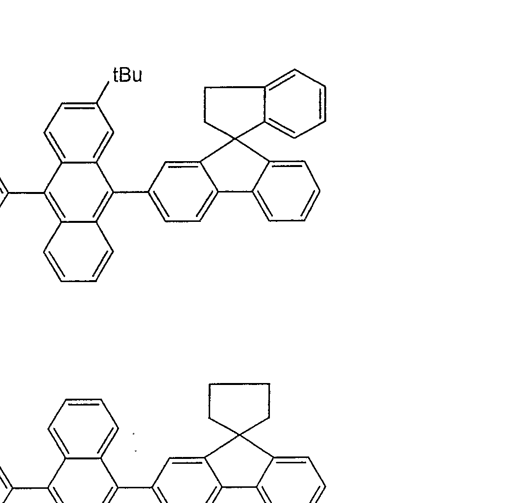
- An 4 of Comparative Example 4 had a relatively low symmetry because a substituent was introduced into the anthracene ring, but was still insufficient and crystallization occurred. It has been found that a substituent having at least 4 carbon atoms is required to prevent crystallization.
- AN7 in Example 13 had a spirofluorenyl group having a large molecular weight, but had only one place, and thus did not undergo thermal decomposition as in Comparative Example 5 and had a vapor deposition temperature of 4. Vapor deposition was performed at a temperature of 0 ° C or lower. Therefore, blue uniform light emission was obtained, and the luminous efficiency was higher than that of Comparative Example 5.
- AN 11 in Example 14 has a spiro skeleton, the molecular weight is smaller than that of the spirofluorenyl group.
- the film could be deposited at a deposition temperature of 400 ° C. or less without being thermally decomposed. Accordingly, blue uniform light emission was obtained, and the luminous efficiency was higher than that of Comparative Example 5.
- Example 8 an organic EL device was manufactured in the same manner except that the following D2 was used instead of D1 as the light-emitting material, and the luminous efficiency was measured in the same manner, and the state of the light-emitting surface was observed.
- the luminous efficiency was 5.0 cd / A
- the light emission was pure blue
- the light emitting surface after the storage at 120 ° C for 500 hours maintained uniform light emission.
- the organic EL device using the anthracene derivative of the present invention has high luminous efficiency, can emit light uniformly even when driven for a long time at a high temperature, and can be used at a high temperature.
Abstract
Description


Claims


Priority Applications (3)
| Application Number | Priority Date | Filing Date | Title |
|---|---|---|---|
| US10/519,934 US20050233165A1 (en) | 2002-08-02 | 2003-07-29 | Anthracene derivatives and organic electroluminescent devices made by using the same |
| EP03766655A EP1533289A4 (en) | 2002-08-02 | 2003-07-29 | Anthracene derivatives and organic electroluminescent devices made by using the same |
| US12/585,067 US20090321729A1 (en) | 2002-08-02 | 2009-09-02 | Anthracene Derivatives and Organic Electroluminescent Devices Made by Using the Same |
Applications Claiming Priority (2)
| Application Number | Priority Date | Filing Date | Title |
|---|---|---|---|
| JP2002225636A JP4025137B2 (en) | 2002-08-02 | 2002-08-02 | Anthracene derivative and organic electroluminescence device using the same |
| JP2002-225636 | 2002-08-02 |
Related Child Applications (1)
| Application Number | Title | Priority Date | Filing Date |
|---|---|---|---|
| US12/585,067 Continuation US20090321729A1 (en) | 2002-08-02 | 2009-09-02 | Anthracene Derivatives and Organic Electroluminescent Devices Made by Using the Same |
Publications (1)
| Publication Number | Publication Date |
|---|---|
| WO2004013073A1 true WO2004013073A1 (en) | 2004-02-12 |
Family
ID=31492162
Family Applications (1)
| Application Number | Title | Priority Date | Filing Date |
|---|---|---|---|
| PCT/JP2003/009606 WO2004013073A1 (en) | 2002-08-02 | 2003-07-29 | Anthracene derivatives and organic electroluminescent devices made by using the same |
Country Status (7)
| Country | Link |
|---|---|
| US (2) | US20050233165A1 (en) |
| EP (1) | EP1533289A4 (en) |
| JP (1) | JP4025137B2 (en) |
| KR (1) | KR20050025195A (en) |
| CN (3) | CN1971971A (en) |
| TW (1) | TW200402405A (en) |
| WO (1) | WO2004013073A1 (en) |
Cited By (93)
| Publication number | Priority date | Publication date | Assignee | Title |
|---|---|---|---|---|
| WO2005101540A2 (en) * | 2004-04-12 | 2005-10-27 | Eastman Kodak Company | Oled device with short reduction |
| EP1623968A1 (en) * | 2003-05-15 | 2006-02-08 | Idemitsu Kosan Co., Ltd. | Compound having spiro bond, material for luminescent coating formation and organic electroluminescence element including the same |
| WO2007021117A1 (en) * | 2005-08-16 | 2007-02-22 | Gracel Display Inc. | Green electroluminescent compounds and organic electroluminescent device using the same |
| WO2007022845A1 (en) | 2005-08-26 | 2007-03-01 | Merck Patent Gmbh | Novel materials for organic electroluminescent devices |
| EP1780191A1 (en) * | 2004-06-16 | 2007-05-02 | Idemitsu Kosan Co., Ltd. | Fluorene derivative and organic electroluminescent device using same |
| WO2007110129A1 (en) | 2006-03-24 | 2007-10-04 | Merck Patent Gmbh | New materials for organic electroluminescent devices |
| WO2008006449A1 (en) | 2006-07-11 | 2008-01-17 | Merck Patent Gmbh | Novel materials for organic electroluminescent devices |
| WO2008082178A1 (en) * | 2006-12-29 | 2008-07-10 | Doosan Corporation | Diaryl trianthracene derivatives and organic light emitting layer or diode comprising the same |
| DE102007024850A1 (en) | 2007-05-29 | 2008-12-04 | Merck Patent Gmbh | New materials for organic electroluminescent devices |
| DE102008008953A1 (en) | 2008-02-13 | 2009-08-20 | Merck Patent Gmbh | New materials for organic electroluminescent devices |
| DE102008018670A1 (en) | 2008-04-14 | 2009-10-15 | Merck Patent Gmbh | New materials for organic electroluminescent devices |
| WO2010013675A1 (en) * | 2008-07-28 | 2010-02-04 | 出光興産株式会社 | Organic light-emitting medium and organic el element |
| DE102008054141A1 (en) | 2008-10-31 | 2010-05-06 | Merck Patent Gmbh | New materials for organic electroluminescent devices |
| DE102009005746A1 (en) | 2009-01-23 | 2010-07-29 | Merck Patent Gmbh | Materials for organic electroluminescent devices |
| US7851995B2 (en) | 2006-05-05 | 2010-12-14 | Global Oled Technology Llc | Electroluminescent device having improved light output |
| DE102009034625A1 (en) | 2009-07-27 | 2011-02-03 | Merck Patent Gmbh | New materials for organic electroluminescent devices |
| WO2011015265A2 (en) | 2009-08-04 | 2011-02-10 | Merck Patent Gmbh | Electronic devices comprising multi cyclic hydrocarbons |
| DE102009051172A1 (en) | 2009-10-29 | 2011-05-05 | Merck Patent Gmbh | Materials for electronic devices |
| DE102009053191A1 (en) | 2009-11-06 | 2011-05-12 | Merck Patent Gmbh | Materials for electronic devices |
| DE102009052428A1 (en) | 2009-11-10 | 2011-05-12 | Merck Patent Gmbh | Connection for electronic devices |
| DE102009033371A1 (en) | 2009-07-16 | 2011-05-12 | Merck Patent Gmbh | Materials for electronic devices |
| WO2011076314A1 (en) | 2009-12-22 | 2011-06-30 | Merck Patent Gmbh | Electroluminescent formulations |
| WO2011076323A1 (en) | 2009-12-22 | 2011-06-30 | Merck Patent Gmbh | Formulations comprising phase-separated functional materials |
| WO2011076326A1 (en) | 2009-12-22 | 2011-06-30 | Merck Patent Gmbh | Electroluminescent functional surfactants |
| WO2011088877A1 (en) | 2010-01-25 | 2011-07-28 | Merck Patent Gmbh | Compounds for electronic devices |
| DE102010009193A1 (en) | 2010-02-24 | 2011-08-25 | Merck Patent GmbH, 64293 | Fluorine-fluorine associates |
| WO2011110275A2 (en) | 2010-03-11 | 2011-09-15 | Merck Patent Gmbh | Radiative fibers |
| WO2011110277A1 (en) | 2010-03-11 | 2011-09-15 | Merck Patent Gmbh | Fibers in therapy and cosmetics |
| WO2011147522A1 (en) | 2010-05-27 | 2011-12-01 | Merck Patent Gmbh | Compositions comprising quantum dots |
| WO2012013270A1 (en) | 2010-07-26 | 2012-02-02 | Merck Patent Gmbh | Nanocrystals in devices |
| WO2012013272A1 (en) | 2010-07-26 | 2012-02-02 | Merck Patent Gmbh | Quantum dots and hosts |
| US8129037B2 (en) | 2004-10-11 | 2012-03-06 | Merck Patent Gmbh | Phenanthrene derivative |
| DE102010048074A1 (en) | 2010-10-09 | 2012-04-12 | Merck Patent Gmbh | Materials for electronic devices |
| WO2012048780A1 (en) | 2010-10-15 | 2012-04-19 | Merck Patent Gmbh | Compounds for electronic devices |
| DE102010054316A1 (en) | 2010-12-13 | 2012-06-14 | Merck Patent Gmbh | Substituted tetraarylbenzenes |
| DE102011011104A1 (en) | 2011-02-12 | 2012-08-16 | Merck Patent Gmbh | Substituted dibenzonaphthacenes |
| WO2012110178A1 (en) | 2011-02-14 | 2012-08-23 | Merck Patent Gmbh | Device and method for treatment of cells and cell tissue |
| WO2012126566A1 (en) | 2011-03-24 | 2012-09-27 | Merck Patent Gmbh | Organic ionic functional materials |
| WO2012152366A1 (en) | 2011-05-12 | 2012-11-15 | Merck Patent Gmbh | Organic ionic compounds, compositions and electronic devices |
| WO2013113349A1 (en) | 2012-01-30 | 2013-08-08 | Merck Patent Gmbh | Nanocrystals on fibers |
| US8679645B2 (en) | 2005-06-09 | 2014-03-25 | Merck Patent Gmbh | Materials for organic electroluminescence devices |
| US8785001B2 (en) | 2005-12-08 | 2014-07-22 | Merck Patent Gmbh | Organic electroluminescent devices |
| US8795847B2 (en) | 2005-12-08 | 2014-08-05 | Merck Patent Gmbh | Materials for organic electroluminescent devices |
| WO2015165563A1 (en) | 2014-04-30 | 2015-11-05 | Merck Patent Gmbh | Materials for electronic devices |
| WO2015192941A1 (en) | 2014-06-18 | 2015-12-23 | Merck Patent Gmbh | Compositions for electronic devices |
| WO2016034262A1 (en) | 2014-09-05 | 2016-03-10 | Merck Patent Gmbh | Formulations and electronic devices |
| WO2016107663A1 (en) | 2014-12-30 | 2016-07-07 | Merck Patent Gmbh | Formulations and electronic devices |
| WO2016155866A1 (en) | 2015-03-30 | 2016-10-06 | Merck Patent Gmbh | Formulation of an organic functional material comprising a siloxane solvent |
| WO2016198141A1 (en) | 2015-06-12 | 2016-12-15 | Merck Patent Gmbh | Esters containing non-aromatic cycles as solvents for oled formulations |
| WO2017036572A1 (en) | 2015-08-28 | 2017-03-09 | Merck Patent Gmbh | Formulation of an organic functional material comprising an epoxy group containing solvent |
| WO2017097391A1 (en) | 2015-12-10 | 2017-06-15 | Merck Patent Gmbh | Formulations containing ketones comprising non-aromatic cycles |
| WO2017102048A1 (en) | 2015-12-15 | 2017-06-22 | Merck Patent Gmbh | Esters containing aromatic groups as solvents for organic electronic formulations |
| WO2017102049A1 (en) | 2015-12-16 | 2017-06-22 | Merck Patent Gmbh | Formulations containing a mixture of at least two different solvents |
| WO2017102052A1 (en) | 2015-12-16 | 2017-06-22 | Merck Patent Gmbh | Formulations containing a solid solvent |
| WO2017140404A1 (en) | 2016-02-17 | 2017-08-24 | Merck Patent Gmbh | Formulation of an organic functional material |
| WO2017157783A1 (en) | 2016-03-15 | 2017-09-21 | Merck Patent Gmbh | Receptacle comprising a formulation containing at least one organic semiconductor |
| WO2017194435A1 (en) | 2016-05-11 | 2017-11-16 | Merck Patent Gmbh | Compositions for electrochemical cells |
| WO2017216129A1 (en) | 2016-06-16 | 2017-12-21 | Merck Patent Gmbh | Formulation of an organic functional material |
| WO2017216128A1 (en) | 2016-06-17 | 2017-12-21 | Merck Patent Gmbh | Formulation of an organic functional material |
| WO2018001928A1 (en) | 2016-06-28 | 2018-01-04 | Merck Patent Gmbh | Formulation of an organic functional material |
| WO2018024719A1 (en) | 2016-08-04 | 2018-02-08 | Merck Patent Gmbh | Formulation of an organic functional material |
| WO2018077660A1 (en) | 2016-10-31 | 2018-05-03 | Merck Patent Gmbh | Formulation of an organic functional material |
| WO2018077662A1 (en) | 2016-10-31 | 2018-05-03 | Merck Patent Gmbh | Formulation of an organic functional material |
| WO2018087346A1 (en) | 2016-11-14 | 2018-05-17 | Merck Patent Gmbh | Compounds with an acceptor and a donor group |
| WO2018104202A1 (en) | 2016-12-06 | 2018-06-14 | Merck Patent Gmbh | Preparation process for an electronic device |
| WO2018108760A1 (en) | 2016-12-13 | 2018-06-21 | Merck Patent Gmbh | Formulation of an organic functional material |
| WO2018114883A1 (en) | 2016-12-22 | 2018-06-28 | Merck Patent Gmbh | Mixtures comprising at least two organofunctional compounds |
| WO2018138318A1 (en) | 2017-01-30 | 2018-08-02 | Merck Patent Gmbh | Method for forming an organic element of an electronic device |
| WO2018138319A1 (en) | 2017-01-30 | 2018-08-02 | Merck Patent Gmbh | Method for forming an organic electroluminescence (el) element |
| WO2018178136A1 (en) | 2017-03-31 | 2018-10-04 | Merck Patent Gmbh | Printing method for an organic light emitting diode (oled) |
| WO2018189134A1 (en) | 2017-04-13 | 2018-10-18 | Merck Patent Gmbh | Composition for organic electronic devices |
| WO2018189050A1 (en) | 2017-04-10 | 2018-10-18 | Merck Patent Gmbh | Formulation of an organic functional material |
| WO2018202603A1 (en) | 2017-05-03 | 2018-11-08 | Merck Patent Gmbh | Formulation of an organic functional material |
| WO2019016184A1 (en) | 2017-07-18 | 2019-01-24 | Merck Patent Gmbh | Formulation of an organic functional material |
| WO2019115573A1 (en) | 2017-12-15 | 2019-06-20 | Merck Patent Gmbh | Formulation of an organic functional material |
| WO2019162483A1 (en) | 2018-02-26 | 2019-08-29 | Merck Patent Gmbh | Formulation of an organic functional material |
| WO2019238782A1 (en) | 2018-06-15 | 2019-12-19 | Merck Patent Gmbh | Formulation of an organic functional material |
| WO2020064582A1 (en) | 2018-09-24 | 2020-04-02 | Merck Patent Gmbh | Method for the production of a granular material |
| EP3647393A1 (en) | 2013-07-30 | 2020-05-06 | Merck Patent GmbH | Materials for electronic devices |
| WO2020094538A1 (en) | 2018-11-06 | 2020-05-14 | Merck Patent Gmbh | Method for forming an organic element of an electronic device |
| EP3712229A1 (en) | 2013-07-30 | 2020-09-23 | Merck Patent GmbH | Materials for electronic devices |
| WO2021213917A1 (en) | 2020-04-21 | 2021-10-28 | Merck Patent Gmbh | Emulsions comprising organic functional materials |
| WO2021213918A1 (en) | 2020-04-21 | 2021-10-28 | Merck Patent Gmbh | Formulation of an organic functional material |
| WO2021259824A1 (en) | 2020-06-23 | 2021-12-30 | Merck Patent Gmbh | Method for producing a mixture |
| WO2022122607A1 (en) | 2020-12-08 | 2022-06-16 | Merck Patent Gmbh | An ink system and a method for inkjet printing |
| CN114716295A (en) * | 2021-01-04 | 2022-07-08 | 浙江光昊光电科技有限公司 | Fused ring compound and application thereof in organic electronic device |
| WO2022223675A1 (en) | 2021-04-23 | 2022-10-27 | Merck Patent Gmbh | Formulation of an organic functional material |
| WO2022243403A1 (en) | 2021-05-21 | 2022-11-24 | Merck Patent Gmbh | Method for the continuous purification of at least one functional material and device for the continuous purification of at least one functional material |
| US11512039B2 (en) | 2016-11-23 | 2022-11-29 | Guangzhou Chinaray Optoelectronic Materials Ltd. | Aromatic amine derivatives, preparation methods therefor, and uses thereof |
| US11518723B2 (en) | 2016-11-23 | 2022-12-06 | Guangzhou Chinaray Optoelectronic Materials Ltd. | Fused ring compound, high polymer, mixture, composition and organic electronic component |
| WO2023012084A1 (en) | 2021-08-02 | 2023-02-09 | Merck Patent Gmbh | A printing method by combining inks |
| WO2023057327A1 (en) | 2021-10-05 | 2023-04-13 | Merck Patent Gmbh | Method for forming an organic element of an electronic device |
| WO2023237458A1 (en) | 2022-06-07 | 2023-12-14 | Merck Patent Gmbh | Method of printing a functional layer of an electronic device by combining inks |
Families Citing this family (48)
| Publication number | Priority date | Publication date | Assignee | Title |
|---|---|---|---|---|
| KR100924462B1 (en) | 2002-08-23 | 2009-11-03 | 이데미쓰 고산 가부시키가이샤 | Organic electroluminescence device and anthracene derivative |
| JP5015459B2 (en) * | 2003-12-01 | 2012-08-29 | 出光興産株式会社 | Asymmetric monoanthracene derivative, material for organic electroluminescence device, and organic electroluminescence device using the same |
| WO2005061656A1 (en) * | 2003-12-19 | 2005-07-07 | Idemitsu Kosan Co., Ltd. | Light-emitting material for organic electroluminescent device, organic electroluminescent device using same, and material for organic electroluminescent device |
| JP4393249B2 (en) * | 2004-03-31 | 2010-01-06 | 株式会社 日立ディスプレイズ | ORGANIC LIGHT EMITTING ELEMENT, IMAGE DISPLAY DEVICE, AND MANUFACTURING METHOD THEREOF |
| DE102004024075B4 (en) * | 2004-05-13 | 2010-12-23 | BLüCHER GMBH | Adsorption filter material, its use and protective materials |
| CN1960957A (en) * | 2004-05-27 | 2007-05-09 | 出光兴产株式会社 | Asymmetric pyrene derivative and organic electroluminescent device using the same |
| DE102004031000A1 (en) * | 2004-06-26 | 2006-01-12 | Covion Organic Semiconductors Gmbh | Organic electroluminescent devices |
| CN1976883A (en) * | 2004-06-28 | 2007-06-06 | 出光兴产株式会社 | Polycyclic aromatic compound, material for forming light-emitting coating film using the same, and organic electroluminescent device |
| KR100689017B1 (en) | 2004-09-09 | 2007-03-02 | 네오뷰코오롱 주식회사 | Blue luminescent organic compound and organic light-emitting diode including the same |
| JP2006131519A (en) * | 2004-11-04 | 2006-05-25 | Idemitsu Kosan Co Ltd | Condensed ring-containing compound and organic electroluminescent element using the same |
| JP2006140235A (en) * | 2004-11-10 | 2006-06-01 | Idemitsu Kosan Co Ltd | Organic electroluminescence element |
| US7505122B2 (en) * | 2005-04-28 | 2009-03-17 | Semiconductor Energy Laboratory Co., Ltd. | Evaluation method and manufacturing method of light-emitting element material, manufacturing method of light-emitting element, light-emitting element, and light-emitting device and electric appliance having light-emitting element |
| JP2006332034A (en) * | 2005-04-28 | 2006-12-07 | Semiconductor Energy Lab Co Ltd | Evaluation method and manufacturing method of material for light emitting element, manufacturing method of light emitting element, light emitting element, light emitting device having light emitting element and electronic equipment |
| US7479330B2 (en) * | 2005-05-26 | 2009-01-20 | Au Optronics Corporation | Anthracene derivatives for organic electroluminescent device |
| JPWO2007032161A1 (en) * | 2005-09-15 | 2009-03-19 | 出光興産株式会社 | Asymmetric fluorene derivatives and organic electroluminescence devices using them |
| US8298683B2 (en) | 2005-09-15 | 2012-10-30 | Lg Chem, Ltd. | Organic compound and organic light emitting device using the same |
| JP4029897B2 (en) | 2005-10-19 | 2008-01-09 | ソニー株式会社 | Dibenzoanthracene derivative, organic electroluminescent element, and display device |
| KR100851739B1 (en) * | 2006-01-13 | 2008-08-11 | 주식회사 엘지화학 | Emitting materials and organic light emitting device using the same |
| KR100841417B1 (en) * | 2006-10-31 | 2008-06-25 | 주식회사 대림화학 | Electroluminescent compounds and organic electroluminescent device using the same |
| JP2010509775A (en) * | 2006-11-13 | 2010-03-25 | イー・アイ・デュポン・ドウ・ヌムール・アンド・カンパニー | Organic electronic devices |
| KR100807202B1 (en) | 2006-12-29 | 2008-02-28 | 주식회사 두산 | Trianthracene arylamine derivatives and organic light emitting layer or diode comprising the same |
| KR100943535B1 (en) * | 2007-05-10 | 2010-02-22 | 대주전자재료 주식회사 | Spiro type Organic Light Emitting Materials |
| KR100857023B1 (en) * | 2007-05-21 | 2008-09-05 | (주)그라쎌 | Organic electroluminescent compounds and organic light emitting diode using the same |
| FR2920623B1 (en) | 2007-09-03 | 2011-09-23 | Airbus France | FRAME SWITCHING DEVICE FOR AFDX NETWORK. |
| JPWO2009066666A1 (en) * | 2007-11-20 | 2011-04-07 | 出光興産株式会社 | Polymer compound and organic electroluminescence device using the same |
| US20090220680A1 (en) * | 2008-02-29 | 2009-09-03 | Winters Dustin L | Oled device with short reduction |
| US7947974B2 (en) * | 2008-03-25 | 2011-05-24 | Global Oled Technology Llc | OLED device with hole-transport and electron-transport materials |
| KR100910150B1 (en) * | 2008-04-02 | 2009-08-03 | (주)그라쎌 | Novel organic electroluminescent compounds and organic electroluminescent device using the same |
| CN101967079B (en) * | 2009-07-28 | 2013-09-04 | 靳焕改 | Organic material and application thereof in organic electroluminescent devices |
| JP2012020947A (en) * | 2010-07-13 | 2012-02-02 | Canon Inc | New spiro(anthracene-9,9'-fluoren)-10-one compound and organic light-emitting element having the same |
| US8546617B1 (en) | 2012-03-23 | 2013-10-01 | Empire Technology Development Llc | Dioxaborinanes and uses thereof |
| US9290598B2 (en) | 2012-03-29 | 2016-03-22 | Empire Technology Development Llc | Dioxaborinane co-polymers and uses thereof |
| US9095141B2 (en) | 2012-07-31 | 2015-08-04 | Empire Technology Development Llc | Antifouling compositions including dioxaborinanes and uses thereof |
| US9312500B2 (en) | 2012-08-31 | 2016-04-12 | Idemitsu Kosan Co., Ltd. | Organic electroluminescence device |
| RU2572414C2 (en) * | 2013-08-29 | 2016-01-10 | Федеральное государственное бюджетное учреждение науки Институт проблем химической физики Российской академии наук (ИПХФ РАН) | Organic luminescent substance, based on pyrene derivatives, device, and thereof-containing electroluminescent device |
| CN106033798B (en) * | 2015-03-09 | 2017-11-14 | 广东阿格蕾雅光电材料有限公司 | Organic electroluminescence device |
| CN106033801B (en) * | 2015-03-09 | 2018-04-06 | 广东阿格蕾雅光电材料有限公司 | Organic electroluminescence device |
| CN106033793B (en) * | 2015-03-09 | 2018-11-13 | 广东阿格蕾雅光电材料有限公司 | Organic electroluminescence device |
| WO2018009861A1 (en) | 2016-07-08 | 2018-01-11 | Biolegend | Substituted polyfluorene compounds |
| KR102563713B1 (en) | 2017-04-26 | 2023-08-07 | 오티아이 루미오닉스 인크. | Methods of patterning the coating of a surface and apparatus comprising the patterned coating |
| WO2019023463A1 (en) | 2017-07-28 | 2019-01-31 | Biolegend | Conjugated polymers and methods of use |
| KR101981294B1 (en) | 2017-10-31 | 2019-05-23 | 삼성디스플레이 주식회사 | Light absorber and organic electroluminescence device including the same |
| EP3477722B1 (en) * | 2017-10-31 | 2023-09-27 | Samsung Display Co., Ltd. | Light absorber and organic electroluminescence device including the same |
| US11751415B2 (en) | 2018-02-02 | 2023-09-05 | Oti Lumionics Inc. | Materials for forming a nucleation-inhibiting coating and devices incorporating same |
| JP7325731B2 (en) | 2018-08-23 | 2023-08-15 | 国立大学法人九州大学 | organic electroluminescence element |
| KR20210108214A (en) * | 2020-02-25 | 2021-09-02 | 롬엔드하스전자재료코리아유한회사 | Organic electroluminescent compound and organic electroluminescent device comprising the same |
| CN113493445B (en) * | 2020-04-01 | 2022-10-28 | 湖北大学 | Imidazolyl spiro derivative with aggregation-induced emission property and application thereof |
| WO2023078824A1 (en) * | 2021-11-04 | 2023-05-11 | Dottikon Es Holding Ag | Spiro-(indane-fluorene) type compounds and their use in organic electronics |
Citations (2)
| Publication number | Priority date | Publication date | Assignee | Title |
|---|---|---|---|---|
| JP2002154993A (en) * | 2000-08-10 | 2002-05-28 | Mitsui Chemicals Inc | Hydrocarbon compound, material for organic electroluminescent element and organic electroluminescent element |
| JP2003128651A (en) * | 2001-10-16 | 2003-05-08 | Mitsui Chemicals Inc | Hydrocarbon compound, material for organic electroluminescent element and organic electroluminescent element |
Family Cites Families (20)
| Publication number | Priority date | Publication date | Assignee | Title |
|---|---|---|---|---|
| US5759709A (en) * | 1994-03-10 | 1998-06-02 | Sumitomo Chemical Company, Limited | Polymeric fluorescent substance and organic electroluminescence device |
| DE69739752D1 (en) * | 1996-08-19 | 2010-03-18 | Tdk Corp | Organic electroluminescent device |
| US5869929A (en) * | 1997-02-04 | 1999-02-09 | Idemitsu Kosan Co., Ltd. | Multicolor luminescent device |
| US5935721A (en) * | 1998-03-20 | 1999-08-10 | Eastman Kodak Company | Organic electroluminescent elements for stable electroluminescent |
| ATE360892T1 (en) * | 1999-09-21 | 2007-05-15 | Idemitsu Kosan Co | ORGANIC ELECTROLUMINESCENCE AND ORGANIC LUMINESCENT MEDIUM |
| JP2001097897A (en) * | 1999-09-30 | 2001-04-10 | Idemitsu Kosan Co Ltd | Organic compound and organic electroluminescent element using the same |
| AU2001239923A1 (en) * | 2000-02-29 | 2001-09-12 | Thinairapps, Inc. | Flexible wireless advertisement integration in wireless software applications |
| JP4274667B2 (en) * | 2000-03-10 | 2009-06-10 | 三井化学株式会社 | Hydrocarbon compounds and organic electroluminescent devices |
| EP1182183B1 (en) * | 2000-03-29 | 2009-12-09 | Idemitsu Kosan Co., Ltd. | Anthracene derivatives and organic electroluminescent devices made by using the same |
| JP4094203B2 (en) * | 2000-03-30 | 2008-06-04 | 出光興産株式会社 | Organic electroluminescence device and organic light emitting medium |
| US7031931B1 (en) * | 2000-03-30 | 2006-04-18 | Nokia Corporation | Portable device attached to a media player for rating audio/video contents |
| TWI290546B (en) * | 2000-08-10 | 2007-12-01 | Mitsui Chemicals Inc | Hydrocarbon compounds for organic electroluminescent elements and organic electroluminescent elements |
| JP4562884B2 (en) * | 2000-08-25 | 2010-10-13 | 出光興産株式会社 | Organic electroluminescence device |
| KR100377575B1 (en) * | 2000-10-17 | 2003-03-26 | 삼성에스디아이 주식회사 | A blue luiminiscence compound for organic electroluminscene device and the organic electroluminscene device using the same |
| US20030017826A1 (en) * | 2001-07-17 | 2003-01-23 | Dan Fishman | Short-range wireless architecture |
| US20030215667A1 (en) * | 2001-11-02 | 2003-11-20 | Shuang Xie | Electroluminescent devices |
| JP4170655B2 (en) * | 2002-04-17 | 2008-10-22 | 出光興産株式会社 | Novel aromatic compound and organic electroluminescence device using the same |
| CN101068041B (en) * | 2002-07-19 | 2010-08-18 | 出光兴产株式会社 | Organic electroluminescent device and organic light-emitting medium |
| JP4392251B2 (en) * | 2004-01-07 | 2009-12-24 | オークマ株式会社 | Feed drive system controller |
| TWI299355B (en) * | 2005-01-20 | 2008-08-01 | Au Optronics Corp | Organic light emitting diode and display including the same |
-
2002
- 2002-08-02 JP JP2002225636A patent/JP4025137B2/en not_active Expired - Lifetime
-
2003
- 2003-07-29 CN CNA2006101635106A patent/CN1971971A/en active Pending
- 2003-07-29 KR KR1020057001885A patent/KR20050025195A/en not_active Application Discontinuation
- 2003-07-29 US US10/519,934 patent/US20050233165A1/en not_active Abandoned
- 2003-07-29 CN CNA2008100998900A patent/CN101311149A/en active Pending
- 2003-07-29 CN CNA03818561XA patent/CN1675148A/en active Pending
- 2003-07-29 WO PCT/JP2003/009606 patent/WO2004013073A1/en active Application Filing
- 2003-07-29 EP EP03766655A patent/EP1533289A4/en not_active Withdrawn
- 2003-07-31 TW TW092121040A patent/TW200402405A/en unknown
-
2009
- 2009-09-02 US US12/585,067 patent/US20090321729A1/en not_active Abandoned
Patent Citations (2)
| Publication number | Priority date | Publication date | Assignee | Title |
|---|---|---|---|---|
| JP2002154993A (en) * | 2000-08-10 | 2002-05-28 | Mitsui Chemicals Inc | Hydrocarbon compound, material for organic electroluminescent element and organic electroluminescent element |
| JP2003128651A (en) * | 2001-10-16 | 2003-05-08 | Mitsui Chemicals Inc | Hydrocarbon compound, material for organic electroluminescent element and organic electroluminescent element |
Non-Patent Citations (1)
| Title |
|---|
| See also references of EP1533289A4 * |
Cited By (130)
| Publication number | Priority date | Publication date | Assignee | Title |
|---|---|---|---|---|
| EP1623968A4 (en) * | 2003-05-15 | 2007-05-16 | Idemitsu Kosan Co | Compound having spiro bond, material for luminescent coating formation and organic electroluminescence element including the same |
| EP1623968A1 (en) * | 2003-05-15 | 2006-02-08 | Idemitsu Kosan Co., Ltd. | Compound having spiro bond, material for luminescent coating formation and organic electroluminescence element including the same |
| WO2005101540A3 (en) * | 2004-04-12 | 2005-12-29 | Eastman Kodak Co | Oled device with short reduction |
| WO2005101540A2 (en) * | 2004-04-12 | 2005-10-27 | Eastman Kodak Company | Oled device with short reduction |
| US7183707B2 (en) | 2004-04-12 | 2007-02-27 | Eastman Kodak Company | OLED device with short reduction |
| EP1780191A1 (en) * | 2004-06-16 | 2007-05-02 | Idemitsu Kosan Co., Ltd. | Fluorene derivative and organic electroluminescent device using same |
| US7781628B2 (en) | 2004-06-16 | 2010-08-24 | Idemitsu Kosan Co., Ltd. | Fluorene-based derivative and organic electroluminescence device employing the same |
| US8013160B2 (en) | 2004-06-16 | 2011-09-06 | Idemitsu Kosan Co., Ltd. | Fluorene-based derivative and organic electroluminescence device employing the same |
| EP1780191A4 (en) * | 2004-06-16 | 2008-07-02 | Idemitsu Kosan Co | Fluorene derivative and organic electroluminescent device using same |
| US7683225B2 (en) | 2004-06-16 | 2010-03-23 | Idemitsu Kosan Co., Ltd. | Fluorene-based derivative and organic electroluminescence device employing the same |
| KR101213383B1 (en) * | 2004-06-16 | 2012-12-17 | 이데미쓰 고산 가부시키가이샤 | Fluorene derivative and organic electroluminescent device using same |
| EP3287506A1 (en) | 2004-10-11 | 2018-02-28 | Merck Patent GmbH | Phenanthrene derivatives |
| US8129037B2 (en) | 2004-10-11 | 2012-03-06 | Merck Patent Gmbh | Phenanthrene derivative |
| US8679645B2 (en) | 2005-06-09 | 2014-03-25 | Merck Patent Gmbh | Materials for organic electroluminescence devices |
| US9893292B2 (en) | 2005-06-09 | 2018-02-13 | Merck Patent Gmbh | Materials for organic electroluminescence devices |
| CN101243157B (en) * | 2005-08-16 | 2012-09-05 | 葛来西雅帝史派有限公司 | Green electroluminescent compounds and organic electroluminescent device using the same |
| WO2007021117A1 (en) * | 2005-08-16 | 2007-02-22 | Gracel Display Inc. | Green electroluminescent compounds and organic electroluminescent device using the same |
| EP3211058A1 (en) | 2005-08-26 | 2017-08-30 | Merck Patent GmbH | New materials for organic electroluminescent devices |
| WO2007022845A1 (en) | 2005-08-26 | 2007-03-01 | Merck Patent Gmbh | Novel materials for organic electroluminescent devices |
| US8795847B2 (en) | 2005-12-08 | 2014-08-05 | Merck Patent Gmbh | Materials for organic electroluminescent devices |
| US8785001B2 (en) | 2005-12-08 | 2014-07-22 | Merck Patent Gmbh | Organic electroluminescent devices |
| US8999521B2 (en) | 2006-03-24 | 2015-04-07 | Merck Patent Gmbh | Materials for organic electroluminescent devices |
| WO2007110129A1 (en) | 2006-03-24 | 2007-10-04 | Merck Patent Gmbh | New materials for organic electroluminescent devices |
| US7851995B2 (en) | 2006-05-05 | 2010-12-14 | Global Oled Technology Llc | Electroluminescent device having improved light output |
| WO2008006449A1 (en) | 2006-07-11 | 2008-01-17 | Merck Patent Gmbh | Novel materials for organic electroluminescent devices |
| WO2008082178A1 (en) * | 2006-12-29 | 2008-07-10 | Doosan Corporation | Diaryl trianthracene derivatives and organic light emitting layer or diode comprising the same |
| DE102007024850A1 (en) | 2007-05-29 | 2008-12-04 | Merck Patent Gmbh | New materials for organic electroluminescent devices |
| DE102008008953B4 (en) | 2008-02-13 | 2019-05-09 | Merck Patent Gmbh | New materials for organic electroluminescent devices |
| DE102008008953A1 (en) | 2008-02-13 | 2009-08-20 | Merck Patent Gmbh | New materials for organic electroluminescent devices |
| US8993123B2 (en) | 2008-02-13 | 2015-03-31 | Merck Patent Gmbh | Materials for organic electroluminescent devices |
| DE102008018670A1 (en) | 2008-04-14 | 2009-10-15 | Merck Patent Gmbh | New materials for organic electroluminescent devices |
| WO2010013675A1 (en) * | 2008-07-28 | 2010-02-04 | 出光興産株式会社 | Organic light-emitting medium and organic el element |
| DE102008054141A1 (en) | 2008-10-31 | 2010-05-06 | Merck Patent Gmbh | New materials for organic electroluminescent devices |
| WO2010083869A2 (en) | 2009-01-23 | 2010-07-29 | Merck Patent Gmbh | Materials for organic electroluminescence devices |
| US8710284B2 (en) | 2009-01-23 | 2014-04-29 | Merck Patent Gmbh | Materials for organic electroluminescent devices containing substituted 10-benzo[c]phenanthrenes |
| DE102009005746A1 (en) | 2009-01-23 | 2010-07-29 | Merck Patent Gmbh | Materials for organic electroluminescent devices |
| US9006503B2 (en) | 2009-01-23 | 2015-04-14 | Merck Patent Gmbh | Organic electroluminescence devices containing substituted benzo[C]phenanthrenes |
| DE102009033371A1 (en) | 2009-07-16 | 2011-05-12 | Merck Patent Gmbh | Materials for electronic devices |
| WO2011012212A1 (en) | 2009-07-27 | 2011-02-03 | Merck Patent Gmbh | Novel materials for organic electroluminescent devices |
| DE102009034625A1 (en) | 2009-07-27 | 2011-02-03 | Merck Patent Gmbh | New materials for organic electroluminescent devices |
| WO2011015265A2 (en) | 2009-08-04 | 2011-02-10 | Merck Patent Gmbh | Electronic devices comprising multi cyclic hydrocarbons |
| DE102009051172A1 (en) | 2009-10-29 | 2011-05-05 | Merck Patent Gmbh | Materials for electronic devices |
| WO2011050888A1 (en) | 2009-10-29 | 2011-05-05 | Merck Patent Gmbh | Materials for electronic devices |
| WO2011054442A2 (en) | 2009-11-06 | 2011-05-12 | Merck Patent Gmbh | Materials for electronic devices |
| DE102009053191A1 (en) | 2009-11-06 | 2011-05-12 | Merck Patent Gmbh | Materials for electronic devices |
| WO2011057701A1 (en) | 2009-11-10 | 2011-05-19 | Merck Patent Gmbh | Organic compounds for electroluminescent devices |
| DE102009052428A1 (en) | 2009-11-10 | 2011-05-12 | Merck Patent Gmbh | Connection for electronic devices |
| WO2011076314A1 (en) | 2009-12-22 | 2011-06-30 | Merck Patent Gmbh | Electroluminescent formulations |
| WO2011076326A1 (en) | 2009-12-22 | 2011-06-30 | Merck Patent Gmbh | Electroluminescent functional surfactants |
| WO2011076323A1 (en) | 2009-12-22 | 2011-06-30 | Merck Patent Gmbh | Formulations comprising phase-separated functional materials |
| DE102010005697A1 (en) | 2010-01-25 | 2011-07-28 | Merck Patent GmbH, 64293 | Connections for electronic devices |
| WO2011088877A1 (en) | 2010-01-25 | 2011-07-28 | Merck Patent Gmbh | Compounds for electronic devices |
| DE102010009193B4 (en) | 2010-02-24 | 2022-05-19 | MERCK Patent Gesellschaft mit beschränkter Haftung | Composition containing fluorine-fluorine associates, processes for their production, their use and organic electronic devices containing them |
| DE102010009193A1 (en) | 2010-02-24 | 2011-08-25 | Merck Patent GmbH, 64293 | Fluorine-fluorine associates |
| WO2011103953A1 (en) | 2010-02-24 | 2011-09-01 | Merck Patent Gmbh | Fluorine-fluorine associates |
| WO2011110275A2 (en) | 2010-03-11 | 2011-09-15 | Merck Patent Gmbh | Radiative fibers |
| WO2011110277A1 (en) | 2010-03-11 | 2011-09-15 | Merck Patent Gmbh | Fibers in therapy and cosmetics |
| WO2011147522A1 (en) | 2010-05-27 | 2011-12-01 | Merck Patent Gmbh | Compositions comprising quantum dots |
| EP3309236A1 (en) | 2010-05-27 | 2018-04-18 | Merck Patent GmbH | Compositions comprising quantum dots |
| WO2012013270A1 (en) | 2010-07-26 | 2012-02-02 | Merck Patent Gmbh | Nanocrystals in devices |
| WO2012013272A1 (en) | 2010-07-26 | 2012-02-02 | Merck Patent Gmbh | Quantum dots and hosts |
| WO2012045384A1 (en) | 2010-10-09 | 2012-04-12 | Merck Patent Gmbh | Materials for electronic devices |
| DE102010048074A1 (en) | 2010-10-09 | 2012-04-12 | Merck Patent Gmbh | Materials for electronic devices |
| WO2012048780A1 (en) | 2010-10-15 | 2012-04-19 | Merck Patent Gmbh | Compounds for electronic devices |
| DE102010048607A1 (en) | 2010-10-15 | 2012-04-19 | Merck Patent Gmbh | Connections for electronic devices |
| WO2012079678A1 (en) | 2010-12-13 | 2012-06-21 | Merck Patent Gmbh | Substituted tetraarylbenzenes |
| DE102010054316A1 (en) | 2010-12-13 | 2012-06-14 | Merck Patent Gmbh | Substituted tetraarylbenzenes |
| WO2012107163A1 (en) | 2011-02-12 | 2012-08-16 | Merck Patent Gmbh | Substituted dibenzonaphthacene |
| DE102011011104A1 (en) | 2011-02-12 | 2012-08-16 | Merck Patent Gmbh | Substituted dibenzonaphthacenes |
| WO2012110178A1 (en) | 2011-02-14 | 2012-08-23 | Merck Patent Gmbh | Device and method for treatment of cells and cell tissue |
| WO2012126566A1 (en) | 2011-03-24 | 2012-09-27 | Merck Patent Gmbh | Organic ionic functional materials |
| WO2012152366A1 (en) | 2011-05-12 | 2012-11-15 | Merck Patent Gmbh | Organic ionic compounds, compositions and electronic devices |
| WO2013113349A1 (en) | 2012-01-30 | 2013-08-08 | Merck Patent Gmbh | Nanocrystals on fibers |
| EP3647393A1 (en) | 2013-07-30 | 2020-05-06 | Merck Patent GmbH | Materials for electronic devices |
| EP3712229A1 (en) | 2013-07-30 | 2020-09-23 | Merck Patent GmbH | Materials for electronic devices |
| EP3533794A2 (en) | 2014-04-30 | 2019-09-04 | Merck Patent GmbH | Materials for electronic devices |
| WO2015165563A1 (en) | 2014-04-30 | 2015-11-05 | Merck Patent Gmbh | Materials for electronic devices |
| WO2015192941A1 (en) | 2014-06-18 | 2015-12-23 | Merck Patent Gmbh | Compositions for electronic devices |
| DE102014008722A1 (en) | 2014-06-18 | 2015-12-24 | Merck Patent Gmbh | Compositions for electronic devices |
| WO2016034262A1 (en) | 2014-09-05 | 2016-03-10 | Merck Patent Gmbh | Formulations and electronic devices |
| WO2016107663A1 (en) | 2014-12-30 | 2016-07-07 | Merck Patent Gmbh | Formulations and electronic devices |
| WO2016155866A1 (en) | 2015-03-30 | 2016-10-06 | Merck Patent Gmbh | Formulation of an organic functional material comprising a siloxane solvent |
| WO2016198141A1 (en) | 2015-06-12 | 2016-12-15 | Merck Patent Gmbh | Esters containing non-aromatic cycles as solvents for oled formulations |
| EP3581633A1 (en) | 2015-06-12 | 2019-12-18 | Merck Patent GmbH | Esters containing non-aromatic cycles as solvents for oled formulations |
| WO2017036572A1 (en) | 2015-08-28 | 2017-03-09 | Merck Patent Gmbh | Formulation of an organic functional material comprising an epoxy group containing solvent |
| WO2017097391A1 (en) | 2015-12-10 | 2017-06-15 | Merck Patent Gmbh | Formulations containing ketones comprising non-aromatic cycles |
| WO2017102048A1 (en) | 2015-12-15 | 2017-06-22 | Merck Patent Gmbh | Esters containing aromatic groups as solvents for organic electronic formulations |
| EP4084109A1 (en) | 2015-12-15 | 2022-11-02 | Merck Patent GmbH | Esters containing aromatic groups as solvents for organic electronic formulations |
| WO2017102052A1 (en) | 2015-12-16 | 2017-06-22 | Merck Patent Gmbh | Formulations containing a solid solvent |
| WO2017102049A1 (en) | 2015-12-16 | 2017-06-22 | Merck Patent Gmbh | Formulations containing a mixture of at least two different solvents |
| WO2017140404A1 (en) | 2016-02-17 | 2017-08-24 | Merck Patent Gmbh | Formulation of an organic functional material |
| WO2017157783A1 (en) | 2016-03-15 | 2017-09-21 | Merck Patent Gmbh | Receptacle comprising a formulation containing at least one organic semiconductor |
| DE102016003104A1 (en) | 2016-03-15 | 2017-09-21 | Merck Patent Gmbh | Container comprising a formulation containing at least one organic semiconductor |
| WO2017194435A1 (en) | 2016-05-11 | 2017-11-16 | Merck Patent Gmbh | Compositions for electrochemical cells |
| WO2017216129A1 (en) | 2016-06-16 | 2017-12-21 | Merck Patent Gmbh | Formulation of an organic functional material |
| WO2017216128A1 (en) | 2016-06-17 | 2017-12-21 | Merck Patent Gmbh | Formulation of an organic functional material |
| WO2018001928A1 (en) | 2016-06-28 | 2018-01-04 | Merck Patent Gmbh | Formulation of an organic functional material |
| WO2018024719A1 (en) | 2016-08-04 | 2018-02-08 | Merck Patent Gmbh | Formulation of an organic functional material |
| WO2018077662A1 (en) | 2016-10-31 | 2018-05-03 | Merck Patent Gmbh | Formulation of an organic functional material |
| WO2018077660A1 (en) | 2016-10-31 | 2018-05-03 | Merck Patent Gmbh | Formulation of an organic functional material |
| EP4271163A2 (en) | 2016-11-14 | 2023-11-01 | Merck Patent GmbH | Compounds with an acceptor and a donor group |
| WO2018087346A1 (en) | 2016-11-14 | 2018-05-17 | Merck Patent Gmbh | Compounds with an acceptor and a donor group |
| US11512039B2 (en) | 2016-11-23 | 2022-11-29 | Guangzhou Chinaray Optoelectronic Materials Ltd. | Aromatic amine derivatives, preparation methods therefor, and uses thereof |
| US11518723B2 (en) | 2016-11-23 | 2022-12-06 | Guangzhou Chinaray Optoelectronic Materials Ltd. | Fused ring compound, high polymer, mixture, composition and organic electronic component |
| WO2018104202A1 (en) | 2016-12-06 | 2018-06-14 | Merck Patent Gmbh | Preparation process for an electronic device |
| WO2018108760A1 (en) | 2016-12-13 | 2018-06-21 | Merck Patent Gmbh | Formulation of an organic functional material |
| WO2018114883A1 (en) | 2016-12-22 | 2018-06-28 | Merck Patent Gmbh | Mixtures comprising at least two organofunctional compounds |
| WO2018138318A1 (en) | 2017-01-30 | 2018-08-02 | Merck Patent Gmbh | Method for forming an organic element of an electronic device |
| WO2018138319A1 (en) | 2017-01-30 | 2018-08-02 | Merck Patent Gmbh | Method for forming an organic electroluminescence (el) element |
| WO2018178136A1 (en) | 2017-03-31 | 2018-10-04 | Merck Patent Gmbh | Printing method for an organic light emitting diode (oled) |
| WO2018189050A1 (en) | 2017-04-10 | 2018-10-18 | Merck Patent Gmbh | Formulation of an organic functional material |
| US11778907B2 (en) | 2017-04-13 | 2023-10-03 | Merck Patent Gmbh | Composition for organic electronic devices |
| WO2018189134A1 (en) | 2017-04-13 | 2018-10-18 | Merck Patent Gmbh | Composition for organic electronic devices |
| WO2018202603A1 (en) | 2017-05-03 | 2018-11-08 | Merck Patent Gmbh | Formulation of an organic functional material |
| WO2019016184A1 (en) | 2017-07-18 | 2019-01-24 | Merck Patent Gmbh | Formulation of an organic functional material |
| WO2019115573A1 (en) | 2017-12-15 | 2019-06-20 | Merck Patent Gmbh | Formulation of an organic functional material |
| WO2019162483A1 (en) | 2018-02-26 | 2019-08-29 | Merck Patent Gmbh | Formulation of an organic functional material |
| WO2019238782A1 (en) | 2018-06-15 | 2019-12-19 | Merck Patent Gmbh | Formulation of an organic functional material |
| WO2020064582A1 (en) | 2018-09-24 | 2020-04-02 | Merck Patent Gmbh | Method for the production of a granular material |
| WO2020094538A1 (en) | 2018-11-06 | 2020-05-14 | Merck Patent Gmbh | Method for forming an organic element of an electronic device |
| WO2021213918A1 (en) | 2020-04-21 | 2021-10-28 | Merck Patent Gmbh | Formulation of an organic functional material |
| WO2021213917A1 (en) | 2020-04-21 | 2021-10-28 | Merck Patent Gmbh | Emulsions comprising organic functional materials |
| WO2021259824A1 (en) | 2020-06-23 | 2021-12-30 | Merck Patent Gmbh | Method for producing a mixture |
| WO2022122607A1 (en) | 2020-12-08 | 2022-06-16 | Merck Patent Gmbh | An ink system and a method for inkjet printing |
| CN114716295A (en) * | 2021-01-04 | 2022-07-08 | 浙江光昊光电科技有限公司 | Fused ring compound and application thereof in organic electronic device |
| WO2022223675A1 (en) | 2021-04-23 | 2022-10-27 | Merck Patent Gmbh | Formulation of an organic functional material |
| WO2022243403A1 (en) | 2021-05-21 | 2022-11-24 | Merck Patent Gmbh | Method for the continuous purification of at least one functional material and device for the continuous purification of at least one functional material |
| WO2023012084A1 (en) | 2021-08-02 | 2023-02-09 | Merck Patent Gmbh | A printing method by combining inks |
| WO2023057327A1 (en) | 2021-10-05 | 2023-04-13 | Merck Patent Gmbh | Method for forming an organic element of an electronic device |
| WO2023237458A1 (en) | 2022-06-07 | 2023-12-14 | Merck Patent Gmbh | Method of printing a functional layer of an electronic device by combining inks |
Also Published As
| Publication number | Publication date |
|---|---|
| CN1675148A (en) | 2005-09-28 |
| CN101311149A (en) | 2008-11-26 |
| US20050233165A1 (en) | 2005-10-20 |
| JP4025137B2 (en) | 2007-12-19 |
| JP2004067528A (en) | 2004-03-04 |
| CN1971971A (en) | 2007-05-30 |
| EP1533289A4 (en) | 2009-08-12 |
| TW200402405A (en) | 2004-02-16 |
| US20090321729A1 (en) | 2009-12-31 |
| KR20050025195A (en) | 2005-03-11 |
| EP1533289A1 (en) | 2005-05-25 |
Similar Documents
| Publication | Publication Date | Title |
|---|---|---|
| WO2004013073A1 (en) | Anthracene derivatives and organic electroluminescent devices made by using the same | |
| US10079344B2 (en) | Asymmetric monoanthracene derivative, material for organic electroluminescent device and organic electroluminescent device utilizing the same | |
| JP4025136B2 (en) | Anthracene derivative, light emitting material for organic electroluminescence device, and organic electroluminescence device | |
| JP4864931B2 (en) | Organic electroluminescence device | |
| TWI361020B (en) | ||
| KR101290027B1 (en) | Nitrogenous heterocyclic derivative and organic electroluminescence device making use of the same | |
| WO2003087023A1 (en) | Novel aromatic compound and organic electroluminescnet element containing the same | |
| JPWO2004074399A1 (en) | Material for organic electroluminescence device and organic electroluminescence device using the same | |
| WO2004041774A1 (en) | Aromatic amine derivative and organic electroluminescent element employing the same | |
| KR20080085149A (en) | Material for organic electroluminescent device and organic electroluminescent device | |
| JPWO2007007463A1 (en) | Nitrogen-containing heterocyclic derivative having electron-withdrawing substituent and organic electroluminescence device using the same | |
| KR101026627B1 (en) | Aromatic amine derivative and organic electroluminescence element | |
| KR20050040835A (en) | Novel soluble compound and organic electroluminescent devices | |
| JP4065161B2 (en) | Anthracene derivative and organic electroluminescence device using the same | |
| WO2004110968A1 (en) | Compound having spiro bond, material for luminescent coating formation and organic electroluminescence element including the same | |
| JP2004231547A (en) | Aromatic amine derivative and organic electroluminescent element using the same | |
| WO2009084544A1 (en) | Nitrogen-containing heterocyclic derivative and organic electroluminescent device using the same |
Legal Events
| Date | Code | Title | Description |
|---|---|---|---|
| AK | Designated states |
Kind code of ref document: A1 Designated state(s): CN IN KR US |
|
| AL | Designated countries for regional patents |
Kind code of ref document: A1 Designated state(s): AT BE BG CH CY CZ DE DK EE ES FI FR GB GR HU IE IT LU MC NL PT RO SE SI SK TR |
|
| 121 | Ep: the epo has been informed by wipo that ep was designated in this application | ||
| WWE | Wipo information: entry into national phase |
Ref document number: 10519934 Country of ref document: US |
|
| WWE | Wipo information: entry into national phase |
Ref document number: 2003766655 Country of ref document: EP Ref document number: 3120/CHENP/2004 Country of ref document: IN |
|
| WWE | Wipo information: entry into national phase |
Ref document number: 2003818561X Country of ref document: CN Ref document number: 1020057001885 Country of ref document: KR |
|
| WWP | Wipo information: published in national office |
Ref document number: 1020057001885 Country of ref document: KR |
|
| WWP | Wipo information: published in national office |
Ref document number: 2003766655 Country of ref document: EP |