明 細 書 高強度珪酸カルシウム硬化体 技術分野 Description High-strength cured calcium silicate Technical field
本発明は、 高強度珪酸カルシウム硬化体および高強度珪酸 カルシウム複合体.、 並びにその製造方法に関する。 更に詳し く は、 主と して トバモライ トからなり、 粉末 X線回折におけ る トパモライ トの ( 2 2 0 ) 面の回折ピーク強度 I bが、 ト バモライ トの ( 2 2 0 ) 面と ( 2 2 2 ) 面の 2本の回折ピー クに挾まれた角度領域における回折強度の最低値 I a との間 に、 I b Z l aが 3. 0以上となる関係を持ち、 かつ嵩比重 が 0. 1 4〜 1 . 0であ り、 かつ水銀圧入法で測定される微 分細孔分布曲線の最大値の 1 / 4の高さにおける対数分布幅 が 0. 4 0〜 1. 2 0である ことを特徴とする珪酸カルシゥ ム硬化体に関する。 また、 珪酸カルシウム硬化体と、 補強鉄 筋または補強金網とからなる ことを特徴とする珪酸カルシゥ ム複合体に関する。 更に、 これら珪酸カルシウム硬化体及び 珪酸カルシウム複合体の製造方法に関する。 従来技術 The present invention relates to a high-strength hardened calcium silicate and a high-strength calcium silicate composite, and a method for producing the same. More specifically, the diffraction peak intensity Ib of the (220) plane of topamolites in powder X-ray diffraction is mainly composed of tobermorite, and the (220) planes of tobermorite and ( The relationship between IbZla and the minimum value of the diffraction intensity Ia in the angle region between the two diffraction peaks of the 2 2 2) plane is IbZla of 3.0 or more, and the bulk specific gravity is 0.14 to 1.0, and the logarithmic distribution width at a height of 1/4 of the maximum value of the fine pore distribution curve measured by the mercury intrusion method is 0.40 to 1.20. And a cured product of calcium silicate. The present invention also relates to a calcium silicate composite comprising a hardened calcium silicate and a reinforcing bar or a reinforcing wire mesh. Furthermore, the present invention relates to a method for producing the cured calcium silicate and the calcium silicate composite. Conventional technology
近年、 建築物の軽量化への要望から、 不燃性かつ軽量な建 築材料が求められている。
この様な建材として、 これまでにも軽量気泡コ ンク リー ト (以下屡々 「A L C」 と称する) および繊維補強珪酸カルシ ゥム板(以下屡々 「ケィカル板」 と称する)が知られている。 軽量気泡コ ンク リー トは、 セメン ト、 珪石粉を主原料とし、 これに必要により生石灰粉、 石膏等を加え、 水を添加してス ラ リー状とし気泡剤 ( foaming agent) によ り発泡した後、 型枠で成形してオー トク レープ養生して製造される。 これら 軽量気泡コ ンク リー トは、 嵩比重が 0 . 5 から 0 . 6付近と 軽量であ り、 さ らに結晶性の高い トパモライ ト In recent years, there has been a demand for nonflammable and lightweight building materials due to the demand for lighter buildings. As such building materials, lightweight cellular concrete (hereinafter often referred to as "ALC") and fiber reinforced calcium silicate board (hereinafter often referred to as "carboard") have been known. The lightweight foam concrete is mainly made of cement and silica stone powder, and if necessary, is added with quicklime powder, gypsum, etc., and is added with water to form a slurry, which is foamed with a foaming agent. After that, it is molded in a mold and cured by autoclaving. These lightweight foam concretes have a bulk specific gravity of about 0.5 to about 0.6, and are lightweight and have high crystallinity.
( tobermor i te) ( 5 C a O · 6 S i O 2 · 5 H 20 ) を多量 に含むこ とから長期の耐候性、 耐火性、 不朽性に優れ、 建築 物の外壁材、 床材、 内壁材として広く利用されている。 (Tobermor i te) (5 C a O · 6 S i O 2 · 5 H 2 0) a long-term weather resistance and a this containing a large amount of the refractory, excellent enduring properties, building exterior wall materials, flooring It is widely used as interior wall material.
これら軽量気泡コ ンク リー トの弾性率は、 1 7 0 0〜 2 5 0 O N mm2の範囲にある。 また、 圧縮強度は、 4〜 5 N mm2の範囲にある。 一方、 面材として重要な物性である 曲げ強度は、 素材の強度として 1 N Z m m 2程度と低い。 そ のため、 軽量気泡コンク リー トは内部に捕強鉄筋を配して、 壁、 床、 屋根下地等の部位に用いられてきた。 しかし、 比重 あたり の弾性率 (以下 「比弾性率」 と称する) が十分でない ためにパネルとして用いたときのたわみが大きく、 支持部材 間隔が長い部位には使用できないという問題があった。 また 例えば住宅の床板に用いた場合、 弾性率が十分でないために 重量衝撃音に対する遮音性が悪く 、 軽量気泡コ ンク リー トパ
ネルの上にさ らにモルタルを施工する等の複雑な工法がと ら れてきた。 Modulus of lightweight cellular co link Li DOO is in the range of 1 7 0 0~ 2 5 0 ON mm 2. Also, the compressive strength is in the range of 4 to 5 Nmm 2 . On the other hand, the bending strength, which is an important physical property as a surface material, is as low as 1 NZ mm 2 as the material strength. For this reason, lightweight foam concrete has been used for parts such as walls, floors, and roof bases with a reinforcing steel bar inside. However, since the elastic modulus per specific gravity (hereinafter referred to as “specific elastic modulus”) is not sufficient, there is a problem that the flexure when used as a panel is large, and it cannot be used in a portion where a distance between supporting members is long. For example, when used as a floor panel in a house, the elastic modulus is not sufficient, so that the sound insulation against heavy impact noise is poor, and the lightweight bubble concrete panel is used. Complicated construction methods such as constructing mortar on the flannel have been adopted.
一方、 コ ンク リ ー ト系材料の内部に補強鉄筋を配して使用 する場合、 設計強度は素材の圧縮強度に応じて決定される。 軽量気泡コ ンク リー トは圧縮強度が低いために、 その用途が 制限され、 特に高層階の建築物には使用できないという問題 がある。 また従来の軽量気泡コンク リー トは保釘力が木材等 と比べて著しく低く 、 屋根下地材、 野地板等の釘打ちを要求 される部位への使用が制限されている。 保釘力は弾性率と圧 縮強度の関係、 たとえば弾性率に対する圧縮強度によ り決ま る物性であ り、 軽量気泡コ ンク リー トの場合この値が低いた め、 釘打ちによる局所的な歪みに耐えられず、 釘周辺に微細 な破壊が生じるために十分な保釘力が得られていない。 On the other hand, when reinforcing steel is used inside a concrete material, the design strength is determined according to the compressive strength of the material. Light-weight foam concrete has a low compressive strength, so its use is limited, and there is a problem that it cannot be used especially for high-rise buildings. Further, the conventional lightweight foam concrete has a remarkably low nail retention force as compared with wood or the like, and its use in a place where nailing is required, such as a roof base material or a base plate, is restricted. The nail retention force is a property determined by the relationship between the elastic modulus and the compressive strength, for example, the compressive strength with respect to the elastic modulus. Insufficient enough nail strength was obtained due to inability to withstand distortion and microscopic fracture around the nail.
軽量気泡コンク リ ー トの物性を改善する方法として、 気泡 径分布を制御する、 独立気泡の比率を高める、 トバモライ ト の結晶性を高める、 等の方法が試みられている。 As methods for improving the physical properties of lightweight cellular concrete, methods such as controlling the cell diameter distribution, increasing the ratio of closed cells, and increasing the crystallinity of tobermorite have been attempted.
例えば、 軽量気泡コンク リー トの表面や内部に存在する気 泡が見掛け上、 亀裂として作用するために、 強度を著しく低 下させている との観点から研究がなされ、 例えば日本国特開 平 8 — 6 7 5 7 7号公報には気泡の量を低減した高比重 A L Cに関する技術が開示されている。 しかし、 同公報において も高い圧縮強度を維持できる到達最低比重は 1 . 1程度であ り、 嵩比重 1 . 0 以下では圧縮強度が急激に低下する という
問題があった。 また、 粉末 X線回折における トパモライ トの ( 2 2 0 ) 面の回折ピーク強度 l b と トパモライ トの ( 2 2 0 ) 面と ( 2 2 2 ) 面の 2本の回折ピーク に挟まれた角度領 域における回折強度の最低値 I aの比 I b / I aが 3未満で あ り、 軽量気泡コ ンク リー ト中に一般的に見られる トバモラ イ ト と比較して結晶性が低く耐候性が不十分であ り、 特に大 気中に含まれる二酸化炭素と容易に反応して、 炭酸カルシゥ ムと非晶質珪酸に分解する炭酸化反応を起こす中性化に対す る抵抗が不十分であることから、 外装建材としては使用が制 限されるという問題があった。 For example, research has been conducted from the viewpoint that the bubbles existing on the surface and inside of the lightweight foam concrete apparently act as cracks, thereby significantly reducing the strength. — Japanese Patent Publication No. 6 757 7 discloses a technique related to high specific gravity ALC with a reduced amount of bubbles. However, even in this publication, the minimum specific gravity that can maintain high compressive strength is about 1.1, and when the bulk specific gravity is less than 1.0, the compressive strength rapidly decreases. There was a problem. In addition, the diffraction peak intensity lb of the (220) plane of topamolites in the X-ray powder diffraction and the angular area sandwiched by the two diffraction peaks of the (220) and (2222) planes of topamolites. The ratio Ib / Ia of the minimum value Ia of the diffraction intensity in the region is less than 3, and the crystallinity is lower and the weatherability is lower than that of tobermorite, which is generally found in lightweight cellular concrete. Insufficient, especially inadequate resistance to neutralization, which readily reacts with carbon dioxide contained in the atmosphere and causes a carbonation reaction that decomposes into calcium carbonate and amorphous silicic acid Therefore, there was a problem that the use of exterior building materials was restricted.
また、 例えば日本国特開平 7 — 1 0 1 7 8 7号公報には、 気泡を用いずに軽量化した A L Cに関する技術が開示され、 嵩比重 0. 7以上で圧縮強度 2 O NZmm2を超える建材が 報告されている。 しかし、 該技術における嵩比重 1. 0以下 の硬化体は主として結晶性が極めて低い珪酸カルシウム水和 物からなるために耐候性、 特に大気中の二酸化炭素に対する 中性化抵抗は不十分であることから、 外装建材としては使用 が制限されるという問題があった。 Also, for example, Japanese Patent Application Laid-Open No. Hei 7-1101787 discloses a technology related to ALC that is reduced in weight without using bubbles, and has a bulk specific gravity of 0.7 or more and a compressive strength of more than 2 O NZmm 2 . Building materials have been reported. However, the cured product having a bulk specific gravity of 1.0 or less according to this technique is mainly composed of calcium silicate hydrate having extremely low crystallinity, and therefore has insufficient weather resistance, especially insufficient neutralization resistance to atmospheric carbon dioxide. Therefore, there was a problem that the use as exterior building materials was restricted.
また、 鉄筋を配した外壁や床板等の構造部材として、 板の 長尺化や支持部材間隔の長大化が求められている近年では、 構造設計上、 軽量気泡コ ンク リー トの 3倍の強度を有する材 料が求められている。 例えば、 W09 9 — 4 2 4 1 8号公報 には、 同じ く気泡を用いずに軽量化した A L Cに関する技術
が開示され、 例えば嵩比重 0. 5 2で圧縮強度 1 0 Nノ m m 2、 嵩比重 0. 6 9で圧縮強度 1 91^ / 1111112を越ぇる建材が 報告されている。 しかし、 WO 9 9 — 4 2 4 1 8号公報の技 術における建材では、 水銀圧入法で測定される微分細孔分布 曲線における最大値の 1 Z 4の高さにおける対数分布幅 (以 下屡々 「対数 1ノ 4値幅」 と称する) が 1 . 2 0 を越えてお り、 同じ嵩比重のもので比較した場合、 その圧縮強度は軽量 気泡コ ンク リー トの圧縮強度のせいぜい 2倍が限界である。 さ らに、 弾性率に対する圧縮強度が十分でないという問題が あった。 また、 気泡を用いないため従来の A L C製造設備を 用いる ことができす、 生産性が低下するという問題があ り 、 その生産性低下を補償するに十分な物性向上は得られないと いう問題があった。 In addition, in recent years, as structural members such as outer walls and floorboards with reinforcing bars have been required to have longer lengths and longer spacing between support members, the structural design has required three times the strength of lightweight cellular concrete. There is a need for materials with For example, W09 9 — 4 2 4 18 discloses a technology related to ALC, which is also lightweight without using air bubbles. There is disclosed, for example, compressive strength bulk density 0. 5 2 1 0 N Bruno mm 2, the compressive strength 1 91 ^ / 111111 2 bulk density 0.6 9 Yue Eru building materials have been reported. However, in the building materials in the technology of WO99-424218, the logarithmic distribution width at the height of 1 Z4 of the maximum value in the differential pore distribution curve measured by the mercury intrusion method (hereinafter often referred to as (Referred to as “logarithm 1 value 4-value width”) exceeds 1.20, and when compared with the same bulk specific gravity, the compressive strength is at most twice the compressive strength of lightweight cellular concrete. It is. Furthermore, there was a problem that the compressive strength with respect to the elastic modulus was not sufficient. In addition, conventional ALC manufacturing equipment can be used because no air bubbles are used, and there is a problem that productivity is reduced, and there is a problem that physical properties cannot be sufficiently improved to compensate for the reduced productivity. there were.
一方、 繊維補強珪酸カルシウム板 (ケィカル板) は、 結晶 質あるいは非晶質珪酸質原料と石灰を反応させオー トク レー ブによ り、 補強繊維とともに硬化させたものであり、 繊維の 他に トバモライ ト、 ゾノ トライ ト (xono ite:)、 結晶性が極 めて低い珪酸カルシウム水和物 (以下 「 C S H」 と称する) 等を主な構成物としている。 ゲイカル板の用途は嵩比重 0. 3以下の保温材、 0. 3〜 0. 4の耐火被覆材、 0. 6〜 1 2の耐火建材に大別される。 成形法は、 嵩比重 0. 4以下で はフィ ルタープレス; 嵩比重 0. 6以上では抄造法が用いら れる。
ケィ カル板は、 繊維を 5〜 2 0重量%と多量に含むため、 曲げ強度、 靱性に優れ、 高い加工性を持っている。 反面、 吸 水率および乾燥収縮率が大きく、 寸法精度に劣る。 また、 粉 落ちが多い、 表面硬度が低く キズがっき易いなどの欠点を持 つている。 さ らに C S Hを主構成物とするものは耐候性、 耐 久性に劣っている。 従って、 外装建材としての用途は制限さ れ、 主に内装用建材として用いられている。 またこれらケィ カル板は、 曲げ強度に比較して圧縮強度が低く 、 さ らに弾性 率が非常に低いため、 鉄筋を配して構造部材へ応用する こと は不可能である。 On the other hand, the fiber reinforced calcium silicate board (calcare board) is made by reacting a crystalline or amorphous siliceous raw material with lime and hardening it together with the reinforcing fiber by autoclaving. The main components are xonoite (xonoite :), calcium silicate hydrate with extremely low crystallinity (hereinafter referred to as “CSH”). The use of the gaical board is broadly classified into a heat insulating material having a bulk specific gravity of 0.3 or less, a fire-resistant covering material of 0.3 to 0.4, and a fire-resistant building material of 0.6 to 12. For the molding method, a filter press is used when the bulk specific gravity is 0.4 or less; a papermaking method is used when the bulk specific gravity is 0.6 or more. Since the car board contains a large amount of fiber of 5 to 20% by weight, it has excellent bending strength and toughness, and has high workability. On the other hand, the water absorption and drying shrinkage are large, and the dimensional accuracy is poor. In addition, it has disadvantages such as much powder falling, low surface hardness and easy scratching. Furthermore, those with CSH as the main component are inferior in weather resistance and durability. Therefore, their use as exterior building materials is limited, and they are mainly used as interior building materials. In addition, these car plates have a low compressive strength and a very low elastic modulus as compared with the bending strength, so that it is impossible to apply a reinforcing bar to a structural member.
たとえば日本国特開平 3 — 2 3 7 0 5 1号公報 (米国特許 第 5 , 3 3 0, 5 7 3号公報に対応) では、 トパモライ ト と C S Hと石英と補強繊維からなる珪酸カルシウム成形体及び その製造方法が開示され、 嵩比重 0. 5 5で 1 0:^ / 1111112 以上の曲げ強度を有する建材が報告されている。 しかしなが ら、 同方法では珪酸原料と石灰質原料を 5 0 °C以下の温度で 水と混合することにより、 成形体中の トパモライ トの含有量 を高めよう としているが、 粉末 X線回折における トバモライ トの ( 2 2 0 ) 面の回折ピーク強度 l bと トパモライ トのFor example, Japanese Patent Application Laid-Open No. Hei 3 — 237051 (corresponding to U.S. Pat. No. 5,330,573) discloses a calcium silicate molded article composed of topamolite, CSH, quartz and reinforcing fibers. and their preparation methods are disclosed, bulk density 0.5 5 1 0: ^ / 111111 building material having two or more bending strength have been reported. However, in this method, the content of topamolite in the compact is increased by mixing the silicic acid raw material and the calcareous raw material with water at a temperature of 50 ° C or less. Diffraction peak intensity (lb) of the (220) plane of tobermorite
( 2 2 0 ) 面と ( 2 2 2 ) 面の 2本の回折ピークに挟まれた 角度領域における回折強度の最低値. I aの比 I b / I aが 3 未満であ り 、 軽量気泡コ ンク リー ト中に一般的に見られる ト パモライ ト と比較して著しく結晶性が低く 、 耐候性、 特に大
気中の二酸化炭素に対する中性化抵抗は不十分である こ とか ら、 外装建材と しては使用できない。 また トバモライ トの結 晶性が低いことに由来して弾性率が非常に低く構造部材と し ての利用はできない。 発明の概要 The lowest value of the diffraction intensity in the angle region sandwiched between the two diffraction peaks of the (2220) plane and the (2222) plane. The crystallinity is significantly lower than that of topamorite commonly found in concrete, and the weather resistance, especially large It cannot be used as an exterior building material because of its insufficient neutralization resistance to atmospheric carbon dioxide. Also, due to the low crystallinity of tobermorite, it has a very low elastic modulus and cannot be used as a structural member. Summary of the Invention
以上の状況に鑑み、 本発明者らは、 硬化体を構成する物質 の結晶性および硬化体中の微細組織に注目 して、 高強度珪酸 カルシウム硬化体および高強度珪酸カルシウム複合体、 並び にその製造方法について鋭意研究を行った。 In view of the above situation, the present inventors focused on the crystallinity of the substance constituting the cured product and the microstructure in the cured product, and focused on the high-strength calcium silicate cured product and the high-strength calcium silicate composite, We conducted intensive research on the manufacturing method.
その結果、 意外にも、 少なく とも珪酸質原料とセメ ン ト と 石灰質原料を含む水性スラリーを型枠に注入し、 予備硬化し た後にオー トク レープ養生し、 主として トバモライ トからな る珪酸カルシウム硬化体を製造する際に、 5 0重量%以上が 結晶質である珪酸質原料を用い、 硫酸アルミニウムまたはそ の水和物およびその他の硫酸化合物を配合する ことによ り 、 高結晶性の トパモライ 卜を多量に含有し、 かつ、 微細な細孔 が均一に分布するという、 従来にない微細構造を有する珪酸 カルシウム硬化体を得る ことができる ことを見出した。 また 硫酸アルミニウムもしく はその水和物を用いる ことによ り、 ' 高い水/固体比の場合にも固液分離を生じさせるこ となく成 形体が得られるこ とから、 粗大気泡の量が自由に制御された 嵩比重の低い珪酸カルシウム硬化体が得られる こと、 更には
気泡剤によって粗大気泡を導入しなく とも、 嵩比重の低い珪 酸カルシウム硬化体が得られる ことを見出した。 As a result, surprisingly, at least an aqueous slurry containing at least a siliceous raw material, cement and calcareous raw material is poured into a mold, pre-cured, then autoclaved, and cured mainly of calcium silicate mainly composed of tobermorite When the body is manufactured, by using a siliceous raw material in which 50% by weight or more is crystalline and blending aluminum sulfate or its hydrate and other sulfate compounds, a highly crystalline topomolite is obtained. It has been found that it is possible to obtain a hardened calcium silicate having an unprecedented microstructure in which a large amount of is contained and fine pores are uniformly distributed. Also, by using aluminum sulfate or its hydrate, it is possible to obtain a molded body without causing solid-liquid separation even at a high water / solid ratio, so that the amount of coarse bubbles is reduced. It is possible to obtain a freely controlled calcium silicate cured product having a low bulk specific gravity. It has been found that a cured product of calcium silicate having a low bulk specific gravity can be obtained without introducing coarse bubbles by a foaming agent.
本発明は、 これら珪酸カルシウム硬化体が、 従来にない微 細構造を有する ことによ り、 気泡剤による粗大気泡が存在し ても、 従来の軽量気泡コ ンク リー トの数倍の強度、 弾性率、 かつ弾性率に対する圧縮強度を発現する こと、 気泡剤による 粗大気泡が存在しない場合にはさ らに 1 . 5 〜 2 . 0 倍の上 記物性を発揮する こと、 かつ従来の軽量気泡コ ンク リ ー トの 欠点であった欠け易さを大幅に改善し保釘力に代表される釘 打ち性能を大幅に改善する ことができる一方、 高い加工性を も有する ことを見出したこと、 さ らに従来の繊維補強珪酸カ ルシゥム板に比べて高い弾性率、 高い圧縮強度および高耐久 性を有する こ とを見出したことに基づく ものでもある。 According to the present invention, the hardened calcium silicate has an unprecedented fine structure, so that even if coarse bubbles due to a foaming agent are present, the strength and elasticity are several times that of a conventional lightweight foam concrete. To exhibit compressive strength with respect to modulus and elastic modulus, to exhibit 1.5 to 2.0 times the above-mentioned properties in the absence of coarse bubbles due to the foaming agent, and to use conventional lightweight foam cores. It has been found that while it is possible to significantly improve the ease of chipping, which has been a drawback of concrete, and to significantly improve nailing performance represented by nail retention, it also has high workability. Furthermore, they are based on the finding that they have higher elastic modulus, higher compressive strength and higher durability than conventional fiber-reinforced calcium silicate plates.
従って、 本発明の目的は、 嵩比重が 0 . 1 4〜 1 . 0 と軽 量であ り ながら、 建築材料として好適な高比圧縮強度、 高比 弾性率かつ弾性率に対する高い圧縮強度、 さ らには中性化抵 抗に優れた珪酸カルシウム硬化体、 さ らにそれらに加えて、 寸法安定性、 耐欠け性、 釘打ち性能に優れた珪酸カルシウム 硬化体、 およびそれに加えて構造部材に要求される設計強度 を有した珪酸カルシウム複合体、 並びにそれらの製造方法を 提供する ことにある。 Therefore, an object of the present invention is to achieve a high specific compressive strength, a high specific elasticity and a high compressive strength relative to an elastic modulus, which are suitable as building materials, while having a bulk specific gravity of 0.14 to 1.0. In addition to these, there are hardened calcium silicates with excellent neutralization resistance, and in addition, hardened calcium silicates with excellent dimensional stability, chipping resistance and nailing performance, and in addition to structural members An object of the present invention is to provide a calcium silicate composite having required design strength, and a method for producing the same.
本発明の上記及び他の諸目的、 諸特徴ならびに諸利益は、 添付の図面を参照しながら述べる次の詳細な説明及び請求の
範囲から明らかになる。 図面の簡単な説明 The above and other objects, features and advantages of the present invention are set forth in the following detailed description and claims, taken in conjunction with the accompanying drawings. It will be clear from the range. BRIEF DESCRIPTION OF THE FIGURES
図 1 (A) 及び図 1 ( B) は、 珪酸カルシウム硬化体の粉 末 X線回折データ及び、 I a、 l bの算出方法を示す X線回 折図である。 尚、 各図において C P S とは、 counts per secondの意味である。 FIGS. 1 (A) and 1 (B) are X-ray diffraction data showing the powder X-ray diffraction data of the cured calcium silicate and the method of calculating Ia and lb. In each drawing, CPS means counts per second.
図 1 (A) : 実施例 1 の珪酸カルシウム硬化体の粉末 X線回 折データ及び、 I a、 I bの算出方法を示す X線回折図であ る。 FIG. 1 (A) is an X-ray diffraction pattern showing the powder X-ray diffraction data of the cured calcium silicate of Example 1 and the method of calculating Ia and Ib.
図 1 ( B ) : 比較例 3 2の珪酸カルシウム硬化体の粉末 X線 回折データ及び、 I a、 l bの算出方法を示す X線回折図で ある。 FIG. 1 (B): X-ray diffraction data showing the powder X-ray diffraction data of the cured calcium silicate of Comparative Example 32 and the method of calculating Ia and lb.
図 2 ( A ) 〜図 2 ( C ) は、 水銀圧入法によ り測定された 珪酸カルシウム硬化体の微分細孔分布及び、 対数 1 4値幅 の算出方法を示す分布図である。 FIGS. 2 (A) to 2 (C) are distribution diagrams showing a method for calculating the differential pore distribution and the logarithmic 14 value width of the cured calcium silicate measured by the mercury intrusion method.
図 2 ( A ) : 実施例 1 の珪酸カルシウム硬化体の微分細孔分 布及び、 対数 1 4値幅の算出方法を示す分布図である。 図 2 ( B ) : 比較例 2 1 の珪酸カルシウム硬化体の微分細孔 分布及び、 対数 1 Z 4値幅の算出方法を示す分布図である。 図 2 ( C ) : 特異な微分細孔分布を有する珪酸カルシウム硬 化体における対数 1ノ 4値幅の算出方法を示す分布図である 図 3は、 実施例 1 の珪酸カルシウム硬化体の粉末 X線回折
データ及び、 I ( 0 0 2 ) 、 I ( 2 2 0 ) の算出方法を示す X線回折図である。 尚、 図 3 において C P S とは、 counts per second の意味である。 FIG. 2 (A): A distribution diagram showing the differential pore distribution of the cured calcium silicate of Example 1 and the method of calculating the log 14 value width. FIG. 2 (B): is a distribution diagram showing a method for calculating a differential pore distribution and a logarithmic 1Z 4-value width of the cured calcium silicate of Comparative Example 21. Fig. 2 (C): Distribution diagram showing the method of calculating the logarithmic 1 to 4 value width of the hardened calcium silicate having a unique differential pore distribution. diffraction FIG. 3 is an X-ray diffraction diagram showing data and a method of calculating I (002) and I (220). In Fig. 3, CPS means counts per second.
図 4 は、 水銀圧入法によ り測定された珪酸カルシウム硬化 体の微分細孔分布を示す分布図であ り、 (A) は実施例 2 の 珪酸カルシウム硬化体の微分細孔分布を示し、 ( B ) は、 比 較例 2 の珪酸カルシウム硬化体の微分細孔分布を示す。 FIG. 4 is a distribution diagram showing the differential pore distribution of the cured calcium silicate measured by the mercury intrusion method, and (A) shows the differential pore distribution of the cured calcium silicate of Example 2. (B) shows the differential pore distribution of the calcium silicate cured product of Comparative Example 2.
図 5 ( A) 〜図 5 (D ) は、 珪酸カルシウム硬化体の走査 型電子顕微鏡写真である。 5 (A) to 5 (D) are scanning electron micrographs of the cured calcium silicate.
図 5 ( A ) : 破断面に トパモライ ト粒子が観測される面積割 合の評価に用いた実施例 1 の珪酸カルシウム硬化体の走査型 電子顕微鏡写真 (顕微鏡設定倍率 2 5 0 0倍) の代表例であ る。 Fig. 5 (A): A scanning electron micrograph (magnification set at 2500 times) of the cured calcium silicate of Example 1 used to evaluate the area ratio in which topamolite particles are observed in the fracture surface. This is an example.
図 5 ( B ) : 実施例 1 の珪酸カルシウム硬化体の走査型電子 顕微鏡写真 (顕微鏡設定倍率 5 0 0 0倍) である。 Fig. 5 (B): Scanning electron micrograph (magnification set at 500,000 times) of the cured product of calcium silicate of Example 1.
図 5 ( C ) : 比較例 2 7 の珪酸カルシウム硬化体の走査型電 子顕微鏡写真 (顕微鏡設定倍率 5 0 0 0倍) である。 Fig. 5 (C): Scanning electron micrograph (magnification set at 500,000 times) of the cured calcium silicate of Comparative Example 27.
図 5 ( D ) : 比較例 3 2 の珪酸カルシウム硬化体の走査型電 子顕微鏡写真 (顕微鏡設定倍率 5 0 0 0倍) である。 Fig. 5 (D): Scanning electron micrograph (magnification set at 500,000 times) of the cured product of calcium silicate of Comparative Example 32.
図 6 は、 水銀圧入法によ り測定された珪酸カルシウム硬化 体の微分細孔分布を示す分布図であ り、 (A) は実施例 2 0 の珪酸カルシウム硬化体の微分細孔分布を示し、 ( B ) は、 比較例 1 5 の珪酸カルシウム硬化体の微分細孔分布を示す。
図 7 は、 水銀圧入法によ り測定された珪酸カルシウム硬化 体の微分細孔分布を示す分布図であり、 (A) は、 実施例 1 8 の珪酸カルシウム硬化体の微分細孔分布を示し、 ( B ) は 比較例 2 7 の珪酸カルシウム硬化体の微分細孔分布を示す。 FIG. 6 is a distribution diagram showing the differential pore distribution of the cured calcium silicate measured by the mercury intrusion method, and (A) shows the differential pore distribution of the cured calcium silicate of Example 20. And (B) shows the differential pore distribution of the cured calcium silicate of Comparative Example 15. FIG. 7 is a distribution diagram showing the differential pore distribution of the cured calcium silicate measured by the mercury intrusion method, and (A) shows the differential pore distribution of the cured calcium silicate of Example 18. And (B) shows the differential pore distribution of the cured calcium silicate of Comparative Example 27.
図 8 ( A ) 〜図 8 ( C ) は、 珪酸カルシウム硬化体の粉末 X線回折データを示す X線回折図である。 尚、 各図において C P S とは、 counts per second の意味である。 8 (A) to 8 (C) are X-ray diffraction diagrams showing powder X-ray diffraction data of the cured calcium silicate. In each figure, CPS means counts per second.
図 8 ( A ) : 実施例 1 の珪酸カルシウム硬化体の粉末 X線回 折データを示す X線回折図である。 FIG. 8 (A): X-ray diffraction diagram showing powder X-ray diffraction data of the cured product of calcium silicate of Example 1.
図 8 ( B ) : 比較例 1 5 の珪酸カルシウム硬化体の粉末 X線 回折デ一タを示す X線回折図である。 FIG. 8 (B): X-ray diffraction diagram showing powder X-ray diffraction data of the cured product of calcium silicate of Comparative Example 15.
図 8 ( C ) : 比較例 2 7 の珪酸カルシウム硬化体の粉末 X線 回折データ を示す X線回折図である。 FIG. 8 (C): X-ray diffraction diagram showing powder X-ray diffraction data of the cured product of calcium silicate of Comparative Example 27.
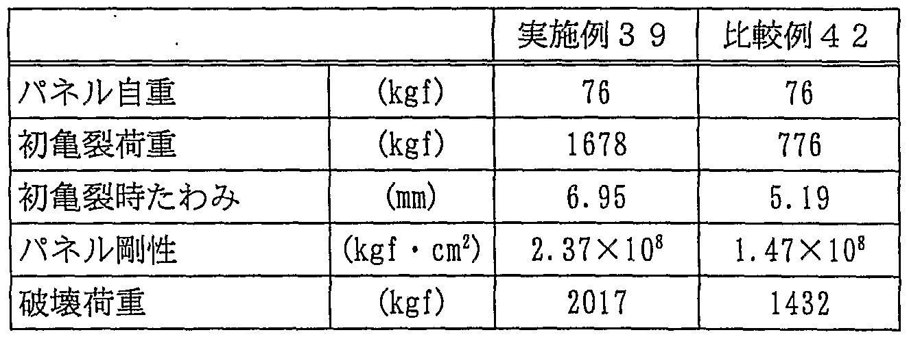
図 9 は、 実施例 3 9および比較例 4 2 の珪酸カルシウム複 合体における補強鉄筋の配置図である。 発明の詳細な説明 FIG. 9 is a layout diagram of reinforcing bars in the calcium silicate composites of Example 39 and Comparative Example 42. Detailed description of the invention
即ち、 本発明の 1 つの態様によれば、 主として トパモライ トからなり 、 粉末 X線回折における トパ乇ライ トの ( 2 2 0 ) 面の回折ピーク強度 I bが、 トノ モライ トの ( 2 2 0 ) 面と ( 2 2 2 ) 面の 2本の回折ピーク に挟まれた角度領域に おける回折強度の最低値 I a との間に、 I b / I aが 3 . 0 以上となる関係を持ち、 かつ嵩比重が 0 . 1 4〜 1 . 0であ
り、 かつ水銀圧入法で測定される微分細孔分布曲線の最大値 の 1ノ 4の高さにおける対数分布幅が 0. 4 0〜 1. 2 0で ある ことを特徴とする珪酸カルシウム硬化体が提供される。 That is, according to one embodiment of the present invention, the diffraction peak intensity Ib of the (220) plane of topalite in powder X-ray diffraction is mainly composed of topomorite, and ) And the minimum value Ia of the diffraction intensity in the angle region between the two diffraction peaks of the (2 2 2) plane has a relationship such that Ib / Ia is 3.0 or more. And the bulk specific gravity is 0.14 to 1.0. And a logarithmic distribution width at a height of 1 to 4 of a maximum value of a differential pore distribution curve measured by a mercury intrusion method is 0.40 to 1.20, wherein the cured product is a calcium silicate. Is provided.
次に、 本発明の理解を容易にするために、 まず本発明の基 本的諸特徵及び好ましい態様を列挙する。 Next, in order to facilitate understanding of the present invention, first, basic features and preferred embodiments of the present invention will be listed.
1. 主として トバモライ トからなり 、 粉末 X線回折における トバモライ トの ( 2 2 0 ) 面の回折ピーク強度 I bが、 トバ モライ トの ( 2 2 0 ) 面と ( 2 2 2 ) 面の 2本の回折ピーク に挟まれた角度領域における回折強度の最低値 I aとの間に I b Z I aが 3. 0以上となる関係を持ち、 かつ嵩比重が 0 1 4〜 1 . 0であ り、 かつ水銀圧入法で測定される微分細孔 分布曲線の最大値の 1 / 4の高さにおける対数分布幅が 0. 4 0〜 1 . 2 0である こ とを特徴とする珪酸カルシウム硬化 体。 1. Mainly composed of tobermorite, the diffraction peak intensity Ib of the (220) plane of tobermorite in powder X-ray diffraction shows two (2,0) and (2,2) planes of tobermorite. And the minimum value of the diffraction intensity Ia in the angle region sandwiched by the diffraction peaks of IbZIa is 3.0 or more, and the bulk specific gravity is 0.14 to 1.0. And a logarithmic distribution width at a height of 1/4 of a maximum value of a differential pore distribution curve measured by a mercury intrusion method is 0.40 to 1.20, wherein the cured product of calcium silicate is .
2. 嵩比重が 0. 1 4〜 0. 9である ことを特徵とする前項 1に記載の珪酸カルシウム硬化体。 2. The cured calcium silicate according to the above item 1, wherein the bulk specific gravity is 0.14 to 0.9.
3. 嵩比重が 0. 2以上 0. 7未満である ことを特徴とする 前項 1 に記載の珪酸カルシウム硬化体。 3. The cured calcium silicate according to item 1, wherein the bulk specific gravity is 0.2 or more and less than 0.7.
4. I b Z l aが 4. 0以上であることを特徴とする前項 1 〜 3 のいずれかに記載の珪酸カルシウム硬化体。
5. 弾性率 Y (N/mm2) と嵩比重 Dから下記式 ( 1 ) を 用いて求め られる値 aが 7以上であり、 かつ圧縮強度 S (N /mm2) と弾性率 Y (N/mm2) から下記式 ( 2 ) を用 いて求め られる値 bが 1. 2 0以上である ことを特徴とする 前項 1〜 4のいずれかに記載の珪酸カルシウム硬化体。 4. The cured calcium silicate according to any one of the above items 1 to 3, wherein IbZla is 4.0 or more. 5. The value a obtained from the elastic modulus Y (N / mm 2 ) and the bulk specific gravity D using the following equation (1) is 7 or more, and the compressive strength S (N / mm 2 ) and the elastic modulus Y (N / mm 2 ), wherein the value b obtained by using the following formula (2) is 1.20 or more: the cured calcium silicate according to any one of the above items 1 to 4.
a = (Y X 1 0 - 3) / (D 1 - 5) ( 1 ) b = S / ( ( Y X 1 0 - 3 ) 1 · 5) ( 2 ) a = (YX 1 0 - 3 ) / (D 1 - 5) (1) b = S / ((YX 1 0 - 3) 1 · 5) (2)
6. 圧縮強度 S (N/mm2) と弾性率 Y (N/mm 2 ) か ら上記式 ( 2 ) を用いて求められる値 bが 1. 3 0以上であ る ことを特徴とする前項 5に記載の珪酸カルシウム硬化体。 6. A value b obtained from the compressive strength S (N / mm 2 ) and the elastic modulus Y (N / mm 2 ) using the above equation (2) is 1.30 or more. 6. The cured product of calcium silicate according to 5.
7. 破断面上の 1 0 mm四方に含まれる最大径 2 0 0 mを 越える気泡が 2 0個よ り多く 、 水銀圧入法で測定される細孔 のうち、 孔径 0. 1 /X m以下の細孔量の割合が、 嵩比重 Dが 0. 5〜 1 . 0の場合には、 下記式 ( 3 ) で計算される7. More than 20 bubbles exceeding the maximum diameter of 200 m contained in a 10 mm square on the fractured surface. Of the pores measured by the mercury intrusion method, the pore diameter is 0.1 / X m or less. When the specific gravity D of the pores is 0.5 to 1.0, the following formula (3) is used.
(D) 〜 9 8 vol%、 Dが 0. 3以上 0. 5未満の場合には、 下記式 ( 4 ) で計算される V 2 (D) 〜 9 5 vol%、 Dが 0. 1 4以上 0. 3未満の場合には下記式 ( 5 ) で計算される V 3 ( D ) 〜 9 0 vol%である こ とを特徴とする前項 1〜 6の いずれかに記載の珪酸カルシウム硬化体。 When (D) to 98 vol% and D is 0.3 or more and less than 0.5, V 2 (D) to 95 vol% calculated by the following equation (4), and D is 0.14 In the case where the value is less than 0.3, V 3 (D) calculated by the following formula (5) is 90 to 90 vol%, and the cured product of calcium silicate according to any one of the above items 1 to 6, .
V x (D ) = 5 0 XD + 4 0 ( 3 )
V 2 (D ) = 1 0 0 XD + 1 5 ( 4 )V x (D) = 50 XD + 40 (3) V 2 (D) = 1 0 0 XD + 1 5 (4)
V 3 (D) = 2 0 0 XD - 1 5 ( 5 ) V 3 (D) = 2 0 0 XD-15 (5)
8. 破断面上の 1 0 mm四方に含まれる最大径 2 0 0 mを 越える気泡が 2 0個以下であ り、 水銀圧入法で測定される細 孔のう ち、 孔径 0. 1 m以下の細孔量の割合が、 嵩比重 D が 0. 8 ~ 1. 0の場合には 9 0〜 9 8 vo 1 %、 Dが 0. 5 以上 0. 8未満の場合には下記式 ( 6 ) で計算される V4 8. No more than 20 bubbles exceeding a maximum diameter of 200 m contained in a 10 mm square on the fractured surface. Of the pores measured by the mercury intrusion method, a pore diameter of 0.1 m or less Is 90 to 98 vo 1% when the bulk specific gravity D is 0.8 to 1.0, and when D is 0.5 or more and less than 0.8, the following formula (6) V 4 calculated by)
( D ) 〜 9 7 vol%、 Dが 0. 1 4以上 0. 5未満の場合に は下記式 ( 7 ) で計算される V 5 ( D ) 〜 9 2 vol%である ことを特徴とする前項 1〜 6のいずれかに記載の珪酸カルシ ゥム硬化体。 (D) ~ 9 7 vol%, and wherein the in case D is 1 less than 4 or more 0.5 0.5 a V 5 (D) ~ 9 2 vol% as calculated by the following formula (7) 7. The cured calcium silicate according to any one of the above items 1 to 6.
V 4 (D) = 1 0 0 XD + 1 0 ( 6 ) V 5 (D ) = 1 5 0 XD— 1 5 ( 7 ) V 4 (D) = 1 0 0 XD + 1 0 (6) V 5 (D) = 1 5 0 XD—1 5 (7)
9. 粉末 X線回折において、 トパモライ トの ( 2 2 0 ) 面の 回折ピーク強度 I bに対する トパモライ ト以外の高結晶性の 共存物質の最強線の回折強度 I c の比 ( I c Z l b ) が 3.9. In powder X-ray diffraction, the ratio (IcZlb) of the diffraction intensity Ic of the strongest line of a highly crystalline coexisting substance other than topamolites to the diffraction peak intensity Ib of the (220) plane of topamolites Is 3.
0以下である ことを特徴とする前項 1 〜 8のいずれかに記載 の珪酸カルシウム硬化体。 9. The cured calcium silicate according to any one of the above items 1 to 8, which is 0 or less.
1 0. 前項 1〜 9のいずれかに記載の珪酸カルシウム硬化体 と、 補強鉄筋または補強金網とからなることを特徵とする珪
酸カルシウム複合体。 10. A silica comprising the cured calcium silicate according to any one of the above items 1 to 9 and a reinforcing steel bar or a reinforcing wire mesh. Calcium acid complex.
1 1 . 少なく とも珪酸質原料とセメ ン ト と石灰質原料を含む 水性スラ リーを型枠に注入し、 予備硬化した後にオー トク レ —ブ養生し、 主として トバモライ トからなる珪酸カルシウム 硬化体を製造する方法であって、 上記珪酸質原料のうち、 5 0重量%以上が結晶質である珪酸質原料であ り、 かつ上記水 性スラ リーが、 硫酸アルミニウムもしく はその水和物を、 酸 化物換算 ( A l 2〇 3 ) で固体原料の総重量に対して 0 . 0 9 〜 1 0重量%、 その他の硫酸化合物を、 上記硫酸アルミ二 ゥムもしく はその水和物を含めて、 S 03量換算で固体原料 の総重量に対して 0. 1 5〜 1 5重量%含有することを特徵 とする珪酸カルシウム硬化体の製造方法。 1 1. Aqueous slurry containing at least siliceous raw material, cement and calcareous raw material is injected into the mold, pre-cured, and then autoclaved to produce a hardened calcium silicate mainly composed of tobamolite. Wherein 50% by weight or more of the siliceous raw material is a crystalline siliceous raw material, and the aqueous slurry contains aluminum sulfate or a hydrate thereof. 0 relative to the total weight of the solid material in the product terms (a l 2 〇 3). 0 9-1 0% by weight, of other sulfate compounds, the aluminum sulfate two © beam also is properly including its hydrate the method of calcium silicate hardened body to Toku徵to 0.5 containing 1 5-1 5% by weight relative to the total weight of the solid material in the S 0 3 amount conversion.
1 2. 予備硬化により得られた予備硬化体を、 型枠からはず した後に、 オー トク レープ養生するこ とを特徴とする前項 1 1 に記載の珪酸カルシウム硬化体の製造方法。 1 2. The method for producing a cured product of calcium silicate according to the above item 11, wherein the pre-cured product obtained by the pre-curing is removed from a mold and then autoclaved.
1 3 . 少なく とも珪酸質原料とセメン トと石灰質原料と水を 固体原料の総重量に対する使用した全ての水の重量比が 0 . 6 7〜 3 . 5 になるよう に混合した後に、 気泡剤としてアル ミニゥム粉末を固体アルミニウム換算で固体原料の総重量に 対して 0 . 0 0 2 〜 0 . 8重量%混合して水性スラ リ ーを得
該水性スラ リーを型枠に注入する ことを特徴とする前項 1 1 又は 1 2 に記載の珪酸カルシウム硬化体の製造方法。 13 3. Mix at least the siliceous raw material, cement, calcareous raw material and water so that the weight ratio of all water used to the total weight of the solid raw material is 0.67 to 3.5, and then use the foaming agent. As an aqueous slurry, 0.02 to 0.8% by weight of aluminum powder was mixed with the total weight of the solid material in terms of solid aluminum to obtain an aqueous slurry. 13. The method for producing a cured calcium silicate according to the above item 11 or 12, wherein the aqueous slurry is injected into a mold.
1 4 . 少なく とも珪酸質原料とセメン ト と石灰質原料と水を . 固体原料の総重量に対する使用した全ての水の重量比が 0 .14. At least the weight ratio of all water used to the total weight of the solid material is 0.
6 7 〜 3 . 5 になるよう に混合した後に、 起泡剤又はその水 溶液に空気を送り込んで作製されたフォームを上記水性スラ リーに対して 5 〜 3 0 O v o i %混合して水性スラ リーを得、 該水性スラ リーを型枠に注入する ことを特徴とする前項 1 1 又は 1 2 に記載の珪酸カルシウム硬化体の製造方法。 After mixing so as to obtain 67 to 3.5, the foam produced by blowing air into the foaming agent or its aqueous solution is mixed with the aqueous slurry in an amount of 5 to 30% by mixing with the aqueous slurry. 13. The method for producing a cured product of calcium silicate according to the above item 11 or 12, wherein a slurry is obtained and the aqueous slurry is poured into a mold.
1 5 . 少なく とも珪酸質原料とセメ ン ト と石灰質原料と水を 固体原料の総重量に対する使用した全ての水の重量比が 0 .15. At least the weight ratio of all water using siliceous raw materials, cement, calcareous raw materials and water to the total weight of solid raw materials is 0.
7 7 〜 5 になるように混合して水性スラ リーを得、 該水性ス ラ リーを型枠に注入する ことを特徴とする前項 1 1又は 1 2 に記載の珪酸カルシウム硬化体の製造方法。 77. The method for producing a hardened calcium silicate according to the above item 11 or 12, wherein the aqueous slurry is mixed by mixing so as to obtain the aqueous slurry, and the aqueous slurry is poured into a mold.
1 6 . 少なく とも珪酸質原料とセメ ン ト と石灰質原料を含む 水性スラ リ ーを得る工程が、 珪酸質原料とセメ ン トと硫酸ァ ルミニゥムもしく はその水和物とその他の硫酸化合物と石灰 質原料の一部と水を混合する第一工程と、 引き続き、 残りの 石灰質原料を加えてさ らに混合する第二工程とを有すること を特徴とする前項 1 1 〜 1 5 のいずれかに記載の珪酸カルシ
ゥム硬化体の製造方法。 16. The process of obtaining an aqueous slurry containing at least a siliceous raw material, cement, and calcareous raw material includes a step of obtaining an aqueous slurry containing the siliceous raw material, cement, aluminum sulfate, or a hydrate thereof and other sulfate compounds. Any one of the above items 11 to 15, characterized by comprising a first step of mixing a part of the calcareous raw material with water and a second step of continuously adding and mixing the remaining calcareous raw material. Silicate calcium described in Manufacturing method of rubber cured body.
1 7 . 少な く と も珪酸質原料とセメ ン ト と石灰質原料を含む 水性スラリ ーを得る工程が、 珪酸質原料とセメ ン ト と水と硫 酸アルミニウムもしく はその水和物と石灰質原料の一部とを 混合する第一工程と、 引き続き、 その他の硫酸化合物および 残り の石灰質原料を加えてさ らに混合する第二工程を有する ことを特徴とする前項 1 1 〜 1 5 のいずれかに記載の珪酸カ ルシゥム硬化体の製造方法。 17. The process of obtaining an aqueous slurry containing at least a siliceous raw material, cement, and calcareous raw material is a process of obtaining a siliceous raw material, cement, water, aluminum sulfate, or a hydrate and calcareous raw material. Any one of the above items 11 to 15, characterized by comprising a first step of mixing a part of the mixture with a second step, followed by a second step of adding another sulfuric acid compound and the remaining calcareous material and further mixing. The method for producing a cured calcium silicate according to the above.
1 8 . 硫酸アルミニウム及びその水和物以外の他の硫酸化合 物が二水石膏である ことを特徴とする前項 1 1 ~ 1 7 のいず れかに記載の珪酸カルシウム硬化体の製造方法。 18. The process for producing a cured calcium silicate according to any one of items 11 to 17, wherein the sulfate compound other than aluminum sulfate and its hydrate is gypsum.
1 9 . 結晶質珪酸原料が、 ブレーン比表面積で 5 0 0 0 〜 3 0 0 0 0 0 c m 2ノ g の微粉珪石である こ とを特徴とする前 項 1 1 〜 1 8 のいずれかに記載の珪酸カルシウム硬化体の製 造方法。 1 9. Crystalline silicate raw materials, either prior to claim 1 1 to 1 8, characterized in that it is a fine powder silica in 5 0 0 0 ~ 3 0 0 0 0 0 cm 2 Roh g in Blaine specific surface area A method for producing the cured calcium silicate according to the above.
2 0 . 前項 1 1 〜 1 9 のいずれかに記載の珪酸カルシウム硬 化体の製造方法において、 補強鉄筋または補強金網が配置さ れた型枠に注入する ことを特徴とする珪酸カルシウム複合体 の製造方法。
本発明における珪酸カルシウム硬化体とは、 珪酸カルシゥ ム化合物を含み、 かつ硬化して得られる任意の形状を有する 建築材料の総称であり、 一般にコンク リ ー ト、 硬化モルタル. 軽量気泡コ ンク リー ト、 ゲイカル板、 珪酸カルシウム板等を 指す。 また、 本発明の珪酸カルシウム複合体とは、 本発明の 珪酸カルシウム硬化体と補強鉄筋または補強金網からなる建 築材料を言う。 20. The method for producing a hardened calcium silicate according to any one of the above items 11 to 19, wherein the calcium silicate composite is injected into a mold provided with a reinforcing steel bar or a reinforcing wire mesh. Production method. The hardened calcium silicate in the present invention is a general term for a building material containing a calcium silicate compound and having an arbitrary shape obtained by hardening, and is generally a concrete or hardened mortar. Lightweight foam concrete , Gaical plate, calcium silicate plate, etc. Further, the calcium silicate composite of the present invention refers to a building material comprising the hardened calcium silicate of the present invention and a reinforcing steel bar or a reinforcing wire mesh.
本発明の珪酸カルシウム硬化体は、 主として トパモライ ト ( 5 C a O · 6 S i 0 2 · 5 H 2 0 ) からなる ことが大きな 特徴である。 トパモライ トは、 軽量気泡コンク リート (A L C ) などの組織中に通常見られる代表的な結晶性珪酸カルシ ゥム水和物の 1 つであ り、 板状あるいは短冊状の粒子形態を とる。 Calcium silicate hardened product of the present invention are mainly Topamorai bets (5 C a O · 6 S 0 2 · 5 H 2 0) becomes It is important feature from. Topamolyte is one of the typical crystalline calcium silicate hydrates commonly found in tissues such as lightweight cellular concrete (ALC) and takes the form of plate-like or strip-like particles.
本発明の珪酸カルシウム硬化体において、 トバモライ トが 主体であるか否かは、 珪酸カルシウム硬化体の破断面の走査 型電子顕微鏡観察と粉末 X線観察を併用する ことによ り以下 のよう に判断する。 In the calcium silicate cured product of the present invention, whether or not tobermorite is mainly determined is determined as follows by using both a scanning electron microscope observation and a powder X-ray observation of the fracture surface of the calcium silicate cured product. I do.
まず第一に、 粉末 X線回折において、 トパモライ トの最強 線 ( 2 2 0 ) を越える他の回折ピークが存在しないこ とであ る。 ただし トバモライ ト とともに、 結晶質シリ カ、 炭酸カル シゥム、 石膏が共存する場合、 トバモライ トが主体であって も、 これら共存物質の高い結晶性のために、 これらの物質の
最強線が トバモライ トの最強線を超える場合がある。 そこで 第二に、 破断面を走査型電子顕微鏡を用いて、 顕微鏡の設定 倍率 2 5 0 0倍、 3 5 . 4 m X 1 8 . 9 mの領域で、 気 泡剤による粗大気泡部以外のマ ト リ ッ クスを無作為に 2 0箇 所観察し、 板状あるいは短冊状の トパモライ ト粒子が観測さ れる面積割合の平均が 5 0 %以上であれば、 主として トパモ ライ トか らなる とする (図 5 ( A ) 参照) 。 また、 上記面積 割合の平均は、 6 0 %以上である ことが好ましく 、 8 0 %以 上である こ とがよ り好ましい。 こ こで粗大気泡部とは、 粗大 気泡および粗大気泡から周囲約 5 ^ mの領域をいい、 自 由空 間が存在するために トバモライ トが生成しやすい領域をいう, しかし、 このような場合でも、 粉末 X線回折において、 トバ モライ トの ( 2 2 0 ) 面の回折ピーク強度 l b に対する トバ モライ ト以外の高結晶性の共存物質、 すなわち結晶質シリ カ 炭酸カルシウム、 石膏の最強線の回折強度 I c の比 ( I c / I b ) が 3 以下であるこ とが好ましく 、 2以下である こ とが よ り好ましい。 こ こで板状あるいは短冊状の粒子とは、 上記 のよう に顕微鏡の設定倍率 2 5 0 0倍で観測された板状ある いは短冊状の トバモライ ト粒子を顕微鏡の設定倍率 5 0 0 0 倍で観察し、 1 つの粒子において、 互いにほぼ平行な 2 つの 表面間の距離がその粒子の最小長さ (以下 「厚み」 と称す る) に相当 し、 その粒子の最大長さが最小長さの 5 倍以上で ある粒子とする (図 5 ( B ) 参照) 。 もちろん、 こ こで言う
最大長さ、 厚みは二次元への投影長さである。 これら トバモ ライ トの粒子の大きさは特に規定はしないが、 最大長さが数 / m〜 l 0 mである こ とが好ましい。 First of all, in the powder X-ray diffraction, there is no other diffraction peak exceeding the strongest line (220) of topamolites. However, when crystalline silica, calcium carbonate, and gypsum coexist with tobermorite, even if tobermorite is the main component, due to the high crystallinity of these coexisting substances, these substances are not used. The strongest line may exceed the tobermorite's strongest line. Then, second, using a scanning electron microscope, the fracture surface was examined at a microscope magnification of 2500 ×, 35.4 mx 18.9 m, except for the large bubbles caused by the foaming agent. The matrix is randomly observed at 20 locations, and if the average area ratio where plate-like or strip-like topomolite particles are observed is 50% or more, it is considered that the matrix mainly consists of topomalite. (See Fig. 5 (A)). Further, the average of the area ratio is preferably 60% or more, more preferably 80% or more. Here, the coarse bubble portion refers to the region around the coarse bubble and about 5 m from the coarse bubble, and a region where tobermorite is easily generated due to the existence of free space. However, in the powder X-ray diffraction, the diffraction peak intensity of the (220) plane of tobamolite was lb, and the coexisting material of high crystallinity other than tobamolite, that is, the diffraction of the strongest line of crystalline calcium carbonate and gypsum The ratio of the intensity I c (I c / I b) is preferably 3 or less, and more preferably 2 or less. Here, the plate-like or strip-like particles refer to the plate-like or strip-like tobermorite particles observed at the microscope setting magnification of 250 × as described above, and the microscope setting magnification of 500 μm. Observed at × 2, the distance between two surfaces almost parallel to each other in one particle corresponds to the minimum length of the particle (hereinafter referred to as “thickness”), and the maximum length of the particle is the minimum length Particles that are at least five times as large as (see Fig. 5 (B)). Of course, say here The maximum length and thickness are the projected lengths in two dimensions. The size of these tobermorite particles is not particularly limited, but the maximum length is preferably several / m to 10 m.
通常トバモライ トは、 低結晶性珪酸カルシウム水和物 ( C S H) と共存することが多い。 C S Hは様々な粒子形態をと ることが知られているが、 通常、 繊維状、 粒状、 塊状の粒子 形態をとるために電子顕微鏡下で トバモライ ト粒子と区別で きる (図 5 ( C ) 、 図 5 ( D ) 参照) 。 この様な C S Hは、 トバモライ トの基本骨格を崩さない範囲で含有できるが、 C S Hは強度、 耐候性、 耐久性など建材と しての様々な必要性 能を低下させるので、 可能な限り含有しないことが好ましい さ らに、 少量の軽量骨材、 補強繊維、 樹脂等も トバモライ ト の基本骨格を崩さない範囲で含有させる ことができる。 Tobermorite usually coexists with low crystalline calcium silicate hydrate (CSH). CSH is known to take various particle morphologies, but usually it can be distinguished from tobermorite particles under an electron microscope due to its fibrous, granular, and massive particle morphology (Fig. 5 (C), See Fig. 5 (D)). Such CSH can be contained in a range that does not destroy the basic skeleton of tobermorite, but CSH is not contained as much as possible because it reduces various necessary properties as a building material such as strength, weather resistance and durability In addition, a small amount of lightweight aggregate, reinforcing fiber, resin, and the like can be contained in a range that does not break the basic skeleton of tobermorite.
本発明の珪酸カルシウム硬化体は粉末 X線回折において観 察される、 2つの トバモライ トの回折線 ( 2 2 0 ) 、 ( 2 2 2 ) に挟まれた角度領域における回折強度の最低値 I aに対 する トパモライ トの ( 2 2 0 ) 回折ピーク強度 l bの比 ( I b / I a ) が 3. 0以上である。 珪酸カルシウム硬化体中に C S Hが多量に存在すると、 前述したよう に建材としての 様々な性質が低下する。 こ こで粉末 X線回折とは、 X線とし て C u K o!線を用いた粉末 X線回折を言う。 珪酸カルシウム 硬化体中に C S Hが多量に存在すると、 乾湿繰り返し時の寸 法安定性が低下する。 さ らに長期間大気中に放置されると、
これら C S Hは大気中に含まれる二酸化炭素と容易に反応し て、 炭酸カルシウムと非晶質珪酸に分解する炭酸化反応を起 こす。 この時、 体積の収縮を伴う ことから亀裂、 組織劣化が 発生する。 嵩比重が 1 . 0以下の場合、 通気性がある程度あ るためにこれら炭酸化反応が内部まで起こ り易く 、 外装用建 材と して使用する場合には致命的な欠陥となる。 トバモライ ト と C S Hが共存する硬化体について、 粉末 X線回折を行う と、 卜パモライ 卜の ( 2 2 0 ) 回折ピーク と ( 2 2 2 ) 回折 ピークに挟まれた領域に、 ブロー ドな C S Hの回折ピークが 認められる。 この C S Hの回折ピークは通常 2 9 . 1 〜 2 9 4 ° ( 2 0 ) 付近に出現する。 また C S Hが トバモライ トに 比べて少ない場合、 C S Hの回折ピークは、 トバモライ トの 回折線に吸収された形になり、 通常 C S Hの回折強度の測定 は不可能となる。 The cured product of calcium silicate of the present invention is observed in powder X-ray diffraction, and has the lowest value of diffraction intensity I a in the angle region between two diffraction lines (220) and (222) of tobermorite. The ratio (I b / I a) of the (220) diffraction peak intensity lb of topamolites with respect to is not less than 3.0. If a large amount of CSH is present in the hardened calcium silicate, various properties as a building material are reduced as described above. Here, powder X-ray diffraction refers to powder X-ray diffraction using Cu K O! Rays as X-rays. If a large amount of CSH is present in the calcium silicate cured product, the dimensional stability during repeated drying and drying will be reduced. If left in the air for a long time, These CSH readily react with the carbon dioxide contained in the atmosphere, causing a carbonation reaction that decomposes into calcium carbonate and amorphous silicic acid. At this time, cracks and structural deterioration occur due to volume shrinkage. When the bulk specific gravity is 1.0 or less, the carbonation reaction easily occurs to the inside due to a certain degree of air permeability, and this is a fatal defect when used as an exterior building material. When X-ray powder diffraction was performed on the cured product in which tobermorite and CSH coexisted, broad CSH was found in the region between the (220) diffraction peak and the (222) diffraction peak of A diffraction peak is observed. The diffraction peak of this CSH usually appears around 29.1 to 29.4 ° (20). If the CSH is smaller than that of tobermorite, the diffraction peak of CSH will be absorbed by the diffraction lines of tobermorite, and it will not be possible to measure the diffraction intensity of CSH.
と ころが C S Hが多量に存在する場合、 卜パモライ トの ( 2 2 0 ) 回折ピーク と ( 2 2 2 ) 回折ピークに挟まれた領 域における X線の回折強度は、 バックグラウン ドに比べて高 い値となる ことから、 C S Hの存在の有無を判定する ことが できる。 珪酸カルシウム硬化体が C S Hを全く含まず、 かつ 高結晶性の トパモライ トを主体とする場合、 同領域における X線強度の最 値はパックグラン ド強度と一致する。 However, when a large amount of CSH is present, the diffraction intensity of X-rays in the region between the (220) diffraction peak and the (222) diffraction peak of topomolite is lower than that in the background. Since the value is high, the presence or absence of CSH can be determined. When the hardened calcium silicate does not contain CSH at all and is mainly composed of topomorite with high crystallinity, the maximum value of the X-ray intensity in the same region coincides with the pack ground intensity.
一方、 たとえ C S Ηが存在しない場合でも、 トパモライ ト の結晶性が低い場合には、 I b / I a は小さく なる。 これは
( 2 2 0 ) と ( 2 2 2 ) が近接しているために、 ピークのす そのが重な り合うためである。 トパモライ トの結晶性が低い と、 珪酸カルシウム硬化体の強度低下、 および耐候性の低下 が起こる。 On the other hand, even if CS I does not exist, if the crystallinity of topamolites is low, I b / I a will be small. this is This is because the peaks of (220) and (222) are close to each other, and the peaks of the peaks overlap. If the crystallinity of topamolites is low, the strength of the cured calcium silicate and the weather resistance are reduced.
従って、 2つの トバモライ トの回折線、 ( 2 2 0 ) と ( 2 2 2 ) に挾まれた角度領域における回折強度の最低値 I aに 対する トバモライ トの ( 2 2 0 ) 面の回折ピーク強度 l bの 比 ( I b / I a ) が大きい程、 珪酸カルシウム硬化体中に含 有される トパモライ トの結晶性が高いことを示す。 また、 珪 酸カルシウム硬化体中に C S Hが存在する場合においては、 I b / I aが大きい程、 珪酸カルシウム硬化体中に含有され る トバモライ トの結晶性が高く 、 かつ C S Hの含有量が少な いことを示す。 Therefore, the diffraction peak intensity on the (2 0 0) plane of tobermorite with respect to the lowest value I a of the diffraction intensity in the angle region between (2 2 0) and (2 2 2) The higher the lb ratio (Ib / Ia), the higher the crystallinity of topamolites contained in the cured calcium silicate. In the case where CSH is present in the cured calcium silicate, as Ib / Ia is larger, the crystallinity of tobermorite contained in the cured calcium silicate is higher and the CSH content is lower. To indicate that
本発明においては、 いずれの場合でも、 I bノ I aの値は 3. 0以上である ことが必要であ り、 好ましく は 4. 0以上 さ らに好ましく は 5. 0以上である。 また、 嵩比重が 0. 5 以上の珪酸カルシウム硬化体においては、 I b Z I aの値が 5. 0以上である と、 特に圧縮強度及び弾性率が高くなり好 ましい。 従来から市販されている軽量気泡コ ンク リー トは、 結晶性の高い珪石を原料として用いる ことによ り、 トバモラ イ トの結晶性を高め、 結果と して I bノ I aの ί直は高くなつ ている場合が多い。 この値が高いにも拘らず強度が低い理由 は、 未反応の珪石が多量に残存していて トバモライ トが真の
主成分になっていないこ と、 および後に述べるように、 マ ト リ ックスに存在する空隙が広い分布を持つこと、 等の理由に よる。 なお、 こ こでの強度 I aおよび I bは、 ノ ックグラン ド強度を含めた値であ り、 後述の I ( 2 2 0 ) とは区別する , I a、 l bの算出方法を図 1 に示すが、 2つの トバモライ ト 回折線 ( 2 2 0 ) , ( 2 2 2 ) に挟まれた角度領域における パッ ク グラン ドを含めた回折強度の最低値を I a、 バック グ ラン ドを含めた トパモライ ト回折線 ( 2 2 0 ) の最大強度を I b とする。 In the present invention, in any case, the value of Ib / Ia needs to be 3.0 or more, preferably 4.0 or more, and more preferably 5.0 or more. In addition, in the cured product of calcium silicate having a bulk specific gravity of 0.5 or more, it is preferable that the value of IbZIa is 5.0 or more, since the compressive strength and the elastic modulus are particularly high. Conventionally available lightweight foam concrete uses high-crystalline silica as a raw material to enhance the crystallinity of tobermorite, and as a result, the Ib / Ia In many cases, it is higher. The reason for the low strength despite this high value is that a large amount of unreacted silica remains and This is because they are not the main component, and as described later, the voids existing in the matrix have a wide distribution. Here, the intensities Ia and Ib are values including the knock ground intensity, and are distinguished from I (220) described later.The calculation method of Ia and lb is shown in FIG. As shown in the figure, the minimum value of the diffraction intensity including the packing ground in the angle region between the two tobermorite diffraction lines (2220) and (222) is defined as Ia and the back ground is included. Let Ib be the maximum intensity of the topamolite diffraction line (220).
本発明の珪酸カルシウム硬化体の嵩比重は、 0 . 1 4〜 1 0 の範囲にあ り、 好ましく は 0 . 1 4〜 0 . 9 、 より好まし く は 0 . 2以上 0 . 7未満である。 こ こで言う嵩比重とは、 1 0 5 °Cで 2 4時間乾燥させた際の嵩比重、 すなわち絶乾比 重を指す。 0 . 1 4未満では本発明の目的とする高い強度は 得られず、 1 . 0 を越えると硬化体の重量が重くなりすぎる ため軽量建材としては適さない。 The bulk specific gravity of the hardened calcium silicate of the present invention is in the range of 0.14 to 10, preferably 0.14 to 0.9, more preferably 0.2 or more and less than 0.7. is there. Here, the bulk specific gravity refers to the bulk specific gravity when dried at 105 ° C. for 24 hours, that is, the absolute dry specific gravity. If it is less than 0.14, the high strength intended by the present invention cannot be obtained, and if it exceeds 1.0, the cured product becomes too heavy and thus is not suitable as a lightweight building material.
本発明の珪酸カルシウム硬化体は、 水銀圧入法で測定され る微分細孔分布曲線における最大値の 1 4 の高さにおける 対数分布幅が 0 . 4 0 〜 1 . 2 0 である ことが必要であ り 、 好ましく は 0 . 4 0 〜 : L . 1 0 、 さ らに好ましく は 0 . 4 0 〜 1 . 0 0である。 The calcium silicate cured product of the present invention needs to have a logarithmic distribution width of 0.40 to 1.20 at a maximum value of 14 in a differential pore distribution curve measured by a mercury intrusion method. Yes, preferably 0.40 to: L.10, and more preferably 0.40 to 1.00.
ここで水銀圧入法とは、 硬化体内部へ水銀を圧入させて、 その時の圧力と侵入量の関係から細孔径の分布を測定するも
のであ り 、 細孔の形状が円筒形である と仮定して計算された ものである。 水銀圧入法による細孔径の測定可能範囲は 6 n m〜 3 6 O jLt mであるが、 この値は実際の細孔の直径を表す ものではなく 、 構成物質間の間隙の大きさの指標として使用 され、 特に本発明の珪酸カルシウム硬化体の細孔構造を記述 する際には有効な解析手段である。 水銀圧入法で測定された '微分細孔分布は、 測定された細孔径に対する細孔量の積算曲 線を 1次微分して得られる。 通常、 嵩比重が 0. 1 4〜 1 . 0の嵩比重が低い珪酸カルシウム硬化体の場合には、 その測 定範囲内の細孔径 6 nm〜 5 0 i mの間に微分細孔分布が存 在する。 Here, the mercury intrusion method is to inject mercury into the inside of the cured product and measure the pore size distribution from the relationship between the pressure and the amount of penetration at that time. It is calculated based on the assumption that the shape of the pores is cylindrical. The measurable range of the pore size by the mercury intrusion method is 6 nm to 36 OjLtm, but this value does not represent the actual pore diameter but is used as an index of the size of the gap between the constituent materials In particular, it is an effective means for describing the pore structure of the cured calcium silicate of the present invention. The 'differential pore distribution' measured by the mercury intrusion method is obtained by first-order differentiation of the integrated curve of the pore volume with respect to the measured pore diameter. Usually, in the case of a hardened calcium silicate having a bulk specific gravity of 0.14 to 1.0 and a low bulk specific gravity, a differential pore distribution exists between the pore diameters of 6 nm to 50 im within the measurement range. Exist.
微分細孔分布曲線における最大値の 1 4の高さにおける 対数分布幅 (対数 1 4値幅) とは、 細孔径分布の広がり を 表す 1つの指標であ り、 微分細孔分布曲線における最大値の 1 4の高さにおける細孔径分布の幅を対数にて表示したも のである。 その算出方法を図 2に示すが、 水銀圧入法によ り 測定された細孔径に対する細孔量の積算曲線を 1次微分して 得られる微分細孔分布曲線における最大値の 1 4の高さを 与える細孔径が二つである場合 (図 2 ( A) 、 図 2 (B) ) 大きい順に A 2、 A iとすると、 対数 1 4値幅は、 A 2、 八ェそれぞれの常用対数の差となる。 尚、 図 2 ( C ) に示す ように、 微分細孔分布曲線における最大値の 1 4の高さを 与える細孔径が二つより多い場合は、 それらのうち最大の細
孔径 A 2の常用対数と最小の細孔径 Aェの常用対数の差とな る。 対数 1 ノ 4値幅が 1 . 2 0 を越えると、 空隙径が 5 0 m以下の細孔領域における細孔径分布は広い分布を持つこ と になり 、 これは即ち、 応力を担う骨格を形成する部分 (以下 「マ ト リ ッ クス」 という) の間隙の均一性が低いこ とを示す, そのために、 局所的な応力集中が生じやすくなり、 弾性率、 圧縮強度、 弾性率に対する圧縮強度の低下をもたらす。 該対 数分布幅は小さい方が強度その他の物性は向上する方向であ るが、 本発明の製造方法をもってしても 0 . 4 0 よ り 小さい 対数分布幅を得ることは難しい。 従来の材料、 たとえば軽量 気泡コ ンク リー トは、 気泡剤により導入された粗大気泡部を 除いた部分、 すなわち骨格を形成するマ ト リ ッ クスに存在す る空隙は広い分布を持ち、 対数 1 Z 4値幅は 1 . 2 0 を越え ている。 従来の材料では、 粗大気泡のみならず、 これら細孔 領域に存在する広い分布を持つ空隙が、 強度、 弾性率等の物 性を改善する こ との障壁になっていたと本発明者らは推測し ている。 The logarithmic distribution width (logarithmic 14-value width) at a height of 14 of the maximum value in the differential pore distribution curve is one index indicating the spread of the pore size distribution, and the maximum value in the differential pore distribution curve is The width of the pore diameter distribution at a height of 14 is expressed as a logarithm. The calculation method is shown in Fig. 2.The maximum value of 14 in the differential pore distribution curve obtained by first-order differentiation of the integrated curve of the pore volume with respect to the pore size measured by the mercury intrusion method (Figure 2 (A), Figure 2 (B)) If A 2 and A i are in descending order, the logarithmic 14 value width is the difference between the common logarithms of A 2 and H Becomes As shown in Fig. 2 (C), when there are more than two pore diameters giving the maximum height of 14 in the differential pore distribution curve, the largest Pore size A difference between the logarithm of common logarithm and the minimum pore size A E of 2 and ing. When the logarithmic 1-to-4 value width exceeds 1.20, the pore size distribution in the pore region having a pore size of 50 m or less has a wide distribution, that is, forms a skeleton that bears stress. This indicates that the uniformity of the gaps in the part (hereinafter referred to as “matrix”) is low, so local stress concentration is likely to occur, and the elastic modulus, compressive strength, and the decrease in compressive strength relative to the elastic modulus Bring. The smaller the log distribution width is, the more the strength and other physical properties are improved, but it is difficult to obtain a log distribution width smaller than 0.40 even by the production method of the present invention. Conventional materials, such as lightweight foam concrete, have a wide distribution of voids in the part excluding the coarse bubbles introduced by the foaming agent, that is, in the matrix forming the skeleton, and have a logarithm of 1 The Z4 value width exceeds 1.20. The present inventors speculate that, in conventional materials, not only coarse bubbles but also voids having a wide distribution existing in these pore regions became barriers to improving physical properties such as strength and elastic modulus. are doing.
ところで、 一般に C S Hは繊維状、 粒状、 塊状の粒子形態 をと り 、 結晶質の トバモライ トより微細である ことに加えて ゲル細孔と呼ばれる 0 . l i m以下の細孔を多量に含有して いる。 そのため、 珪酸カルシウム硬化体中に C S Hが多量に 存在する場合にも対数 1 / 4値幅が非常に小さ くなる こ とが ある。 しかしながら、 対数 1 / 4値幅が小さい場合でも、 C
S Hを多量に含有している場合もしく はトバモライ トの結晶 性が低い場合には、 それらに起因して本発明の珪酸カルシゥ ム硬化体の特徴である、 高い弾性率、 高い圧縮強度、 弾性率 に対する高い圧縮強度は得られない。 By the way, CSH generally takes the form of fibrous, granular, or massive particles, is finer than crystalline tobermorite, and contains a large amount of pores called gel pores of less than 0.1 lim . Therefore, even when a large amount of CSH is present in the hardened calcium silicate, the logarithmic 1/4 width may be extremely small. However, even if the logarithmic 1/4 value width is small, C When a large amount of SH is contained or when the crystallinity of tobermorite is low, the high elastic modulus, high compressive strength, and elasticity characteristic of the calcium silicate cured product of the present invention are attributed to them. No high compressive strength is obtained for the modulus.
本発明の珪酸カルシウム硬化体は、 主として トパモライ ト からなり、 トバモライ トの結晶性の高い、 すなわち上記 I b / I aが 3 . 0 以上の珪酸カルシウム硬化体であ り、 そのマ 卜 リ ックスを構成する トバモライ 卜の板状あるいは短冊状粒 子間の空隙径分布、 すなわちマ ト リ ッ クスにおける細孔分布 を均一化しているこ とが大きな特徴である。 それによ り、 気 泡剤による粗大気泡が存在しても従来の軽量気泡コンク リー 卜の 1 . 7 〜 2 . 2倍の圧縮強度、 弾性率、 かつ弾性率あた り の圧縮強度を発揮する。 また、 気泡剤による粗大気泡が存 在しない場合には、 さ らに 1 . 5 〜 2 . 0倍の上記物性を発 揮する こ とが可能となった。 The hardened calcium silicate of the present invention is mainly made of topamolites, and is a hardened calcium silicate having a high crystallinity of tobermorite, that is, the above Ib / Ia of 3.0 or more. The major feature is that the pore size distribution between the plate-shaped or strip-shaped particles of the tobermorite, that is, the pore distribution in the matrix is made uniform. As a result, even if coarse bubbles due to the foaming agent are present, the compressive strength, elastic modulus, and compressive strength per elastic modulus are 1.7 to 2.2 times that of the conventional lightweight foam concrete. . In addition, when no coarse bubbles due to the foaming agent were present, it was possible to exhibit the above-mentioned physical properties 1.5 to 2.0 times more.
本発明の珪酸カルシウム硬化体は、 従来にない微細構造を 主として トバモライ トからなるマ ト リ ックスによって実現す る ことによ り、 従来の軽量気泡コ ンク リー ト と比較して高い 比弾性率、 比圧縮強度、 さ らには弾性率に対する圧縮強度を 有する。 本発明において、 気泡剤による粗大気泡が存在して も、 従来の軽量気泡コンク リー トの 1 . 7 〜 2 . 2倍の物性 値を発揮する こと、 また粗大気泡が存在しない場合にはさ ら に 1 . 5 〜 2 . 0倍の上記物性値を発揮する ことは、 それぞ
れに重要な意義を有する。 The hardened calcium silicate of the present invention achieves a higher specific elastic modulus and a higher elastic modulus than a conventional lightweight cellular concrete by realizing an unprecedented microstructure mainly by a matrix composed of tobermorite. It has specific compressive strength and compressive strength for the elastic modulus. In the present invention, even if coarse bubbles due to the foaming agent are present, they exhibit 1.7 to 2.2 times the physical property values of the conventional lightweight foam concrete. To exhibit the above physical property value of 1.5 to 2.0 times each time This has important significance.
従来、 軽量気泡コ ンク リー トは、 粗大気泡を含有する こと が高い生産性を可能にしていた。 従って、 本発明によ り 、 従 来用いられてきた設備の範囲もしく は最小限の付加設備によ つて高い生産性を維持しながら従来の数倍の物性値を有する 建材の提供が可能になった。 一方、 気泡剤による粗大気泡を 含有しない場合には、 さ らに著しい物性向上が得られるため に、 従来問題となっていた、 補強鉄筋を用いる場合の用途の 制限をなくすことができる。 即ち、 従来技術では考えられな かった支持部材間隔の長い部位への使用や高層階の建築物へ の使用への展開が可能になり、 生産性の低下を補償するに十 分な効果を有する。 Conventionally, lightweight foam concrete has high productivity because it contains coarse bubbles. Therefore, according to the present invention, it is possible to provide a building material having several times the physical property value of the conventional material while maintaining high productivity with the range of the equipment conventionally used or the minimum additional equipment. became. On the other hand, when coarse bubbles due to the foaming agent are not contained, the remarkable improvement in physical properties can be obtained, so that the limitation on the use of the reinforcing steel bar, which has been a problem in the past, can be eliminated. In other words, it can be used for parts with long spacing between support members and used for high-rise buildings, which were not considered in the conventional technology, and has a sufficient effect to compensate for the decrease in productivity. .
本発明の珪酸カルシウム硬化体が、 最大径 2 0 0 mを越 える気泡を実質的に有する場合には、 水銀圧入法で測定され る細孔のう ち、 細孔径が 0. 1 t m以下の細孔量の割合は、 嵩比重 Dが 0. 5〜 1 . 0の場合には、 下記式 ( 3 ) で求め られる ( D ) 〜 9 8 vol%が好まし く 、 よ り好まし く は 下記式 ( 3 ' ) で求め られる V 1 2 ( D ) 〜 9 8 vol%であ り , 嵩比重 Dが 0. 3以上、 0. 5未満の場合には、 下記式 When the hardened calcium silicate of the present invention substantially has air bubbles exceeding a maximum diameter of 200 m, of the fine pores measured by a mercury intrusion method, the fine pore diameter is 0.1 tm or less. When the bulk specific gravity D is 0.5 to 1.0, the ratio of the pore amount is preferably (D) to 98 vol%, which is obtained by the following equation (3), and more preferably: V 12 (D) to 98 vol% determined by the following equation (3 '). When the bulk specific gravity D is 0.3 or more and less than 0.5, the following equation is used.
( 4 ) で求められる V 2 ( D ) 〜 9 5 v o l %が好ま しく 、 よ り好まし く は下記式 ( 4 ' ) で求め られる V 2 2 (D ) 〜V 2 (D) obtained from (4) is preferably 95 to 95 vol%, and more preferably V 2 2 (D) obtained from the following equation (4 ′).
9 5 vol %であり、 9 5 vol%,
嵩比重 Dが 0. 1 4以上、 0. 3未満の場合には、 下記式
( 5 ) で求められる V 3 ( D ) 〜 9 5 vol%が好ましく 、 よ り好ま しく は下記式 ( 5 ' ) で求められる V 3 2 (D ) 〜 9 O vol%以下である。 When the bulk specific gravity D is 0.14 or more and less than 0.3, the following formula (5) V 3 (D) ~ 9 5 vol% is preferably sought, yo Ri favored properly is less V 3 2 (D) ~ 9 O vol% as determined by the following formula (5 ').
V ! ( D ) = 5 0 XD + 4 0 ( 3 ) 、 V! (D) = 50 XD + 40 (3),
V ? ( D ) = 1 0 0 XD + 1 5 ( 4 ) 、V ? (D) = 1 0 0 XD + 15 (4),
V 3 ( D ) = 2 0 0 X D ( 5 ) , 1 2 ( D ) = 5 0 XD + 4 5 ( 3 、V 3 (D) = 200 XD (5), 1 2 (D) = 50 XD + 45 (3,
V 2 2 ( D ) 0 0 X D + 2 0 ( 4 ' )V 2 2 (D) 0 0 XD + 2 0 (4 ')
V a 2 ( D ) = 2 0 0 XD - 1 0 ( 5 ' ) さ ら に、 本発明の珪酸カルシウム硬化体が、 最大径 2 0 0 mを越える気泡が実質的に無い場合には、 水銀圧入法で測 定される細孔のうち、 細孔径が 0 . 1 m以下の細孔量の割 合は、 V a 2 (D) = 200 XD−10 (5 ′) Furthermore, when the calcium silicate cured product of the present invention has substantially no bubbles exceeding a maximum diameter of 200 m, mercury Of the pores measured by the indentation method, the percentage of the pore volume with a pore diameter of 0.1 m or less is
嵩比重 Dが 0 . 8〜 1 . 0 の場合には、 9 0 〜 9 8 vol%が 好ましく 、 より好ましく は 9 5 ~ 9 8 vol%であ り、 嵩比重 Dが 0 . 5以上 0. 8未満の場合には、 下記式 ( 6 ) で求め られる V 4 ( D ) 〜 9 7 vol%が好ましく 、 よ り好ま しく は下記式 ( 6 ' ) で求められる V 4 2 (D ) 〜 9 7 vol% であり 、 When the bulk specific gravity D is 0.8 to 1.0, it is preferably 90 to 98 vol%, more preferably 95 to 98 vol%, and the bulk specific gravity D is 0.5 or more and 0.5 to 0.9 vol%. If it is less than 8, V 4 (D) ~ 9 7 vol% is preferably obtained by the following formula (6), yo Ri preferred V 4 properly is obtained by the following formula (6 ') 2 (D) ~ 9 7 vol%
嵩比重 Dが 0 . 1 4以上 0 . 5未満の場合には、 下記式 When the bulk specific gravity D is 0.14 or more and less than 0.5,
( 7 ) で求められる V 5 ( D ) 〜 9 2 vol%であるこ とが好 ましく 、 よ り好ましく下記式 ( 7 ' ) で求められる V 5 2 ( D ) 〜 9 2 vol%である。
V 4 ( D ) = 1 0 0 XD + 1 0 ( 6 ) 、 V 5 ( D ) = 1 5 0 XD - 1 5 ( 7 ) 、 V 4 2 ( D ) = 1 0 0 XD + 1 5 ( 6 ' ) 、 V 5 2 ( D ) = 1 5 0 XD - 1 0 ( 7 ' ) 細孔径 0 . 1 m以下の細孔量の割合が上記範囲内であれ ば、 各々の嵩比重において、 よ り高い弾性率、 圧縮強度およ び弾性率に対する圧縮強度を得る こ とができる。 尚、 上限は、 現在の製造方法における限界値である。 (7) V 5 (D) obtained in ~ 9 2 vol% Dearuko TogaYoshimi preferred, a V 5 2 (D) ~ 9 2 vol% as determined by good Ri preferably the following formula (7 '). V 4 (D) = 1 0 0 XD + 1 0 (6), V 5 (D) = 1 5 0 XD - 1 5 (7), V 4 2 (D) = 1 0 0 XD + 1 5 (6 '), V 5 2 (D ) = 1 5 0 XD - 1 0 (7'. if) pore size 0 ratio of ≤ 1 m of pore volume is within the above range, in each of the bulk density, good Ri High elastic modulus, compressive strength, and compressive strength for elastic modulus can be obtained. Note that the upper limit is the limit value in the current manufacturing method.
本発明の珪酸カルシウム硬化体において実質的に最大径が 2 0 0 mを越える気泡を有するとは、 従来の軽量気泡コ ン ク リー ト同様に、 直径約 1 0 0 m〜 l mmの気泡が気泡剤 を用いて導入された場合を意味し、 本発明の珪酸カルシウム 硬化体を破断させて生じた面上において、 1 O mm四方に最 大径が 2 0 0 を越える気泡が 2 0個よ り多いことである, こ こでいう気泡とは、 原料混合時あるいは予備硬化時に気体 が内部に閉じ込められて生じた球状の空隙を言い、 通常、 球. 楕円体、 水滴状、 あるいはこれらが結合した形状をなすこと から、 亀裂や欠けによって発生した空隙とは容易に区別でき る。 In the hardened calcium silicate product of the present invention, having substantially bubbles having a maximum diameter of more than 200 m means that bubbles having a diameter of about 100 m to lmm are in the same manner as a conventional lightweight cell concrete. This means the case where the bubbles were introduced using a foaming agent, and on the surface formed by breaking the calcium silicate cured product of the present invention, 20 bubbles with a maximum diameter exceeding 200 in 1 O mm square were found. The term “bubbles” refers to spherical voids created when gas is trapped inside during raw material mixing or pre-curing, and is usually a sphere. Ellipsoid, water droplet, or a combination of these The shape is easily distinguished from the voids caused by cracks and chips.
一方、 実質的に最大径が 2 0 0 ti mを越える気泡が無いこ ととは、 上記の逆で気泡剤による気泡を含まないことを意味 し、 本発明の珪酸カルシウム硬化体を破断させて生じた面上 において、 1 O mm四方に最大径が 2 0 0 を越える気泡
が 2 0個以下である こととする。 On the other hand, the absence of air bubbles having a maximum diameter substantially exceeding 200 tim means that no air bubbles due to the foaming agent are contained in the reverse of the above, and the cured calcium silicate of the present invention is broken. Bubbles with a maximum diameter of more than 200 in 1 O mm square on the generated surface Is 20 or less.
こ こで言う最大径とは、 破断面上において観察される気 泡の断面形状 (円、 楕円、 水滴状あるいはこれらの合体した 形状等) の最大長さを言う。 これら気泡は実体顕微鏡等を用 いて容易に観察できる。 The maximum diameter here refers to the maximum length of the cross-sectional shape of a bubble (circle, ellipse, water droplet, or a combination thereof) observed on the fracture surface. These bubbles can be easily observed using a stereomicroscope or the like.
上記細孔径 0. 1 m以下の細孔量の割合は、 各々 の嵩比 重におけるマ ト リ ックスの細孔径の微細度、 すなわち緻密度 の指標である。 従って、 本発明の請求項 1 に規定される細孔 径の相対的な分布広さに加えて、 上記細孔径 0. 1 m以下 の細孔量の割合を用いる ことによ り、 応力を担う骨格部であ るマ ト リ ックスにおける細孔径の微細化および均一化度合い の指標を得る ことができる。 すなわち、 上記の条件を満足す る ことは、 各々の嵩比重において、 マ ト リ ッ クスの細孔径を 極限まで微細化しかつ細孔径分布の均一化を実現したもので あ り、 この従来にない微細構造を主と して トバモライ トから なるマ ト リ ッ クスによって実現する こ とによ り、 著しい物性 向上を可能としたものである。 The ratio of the amount of the pores having a pore diameter of 0.1 m or less is an index of the fineness of the pore diameter of the matrix at each bulk density, that is, the density. Therefore, in addition to the relative distribution width of the pore diameter defined in claim 1 of the present invention, the stress is borne by using the ratio of the amount of the pores having the pore diameter of 0.1 m or less. It is possible to obtain an index of the degree of fineness and uniformity of the pore diameter in the matrix as the skeleton. That is, satisfying the above conditions means that the pore diameter of the matrix is reduced to the minimum and the pore diameter distribution is made uniform at each bulk specific gravity. By realizing the matrix mainly composed of tobermorite with a fine structure, it is possible to significantly improve the physical properties.
また、 本発明の珪酸カルシウム硬化体は、 弾性率 Y (Nノ mm2) と嵩比重 Dから下記式 ( 1 ) を用いて求められる値 aがが好ましく は 7以上、 よ り好ましく は 8. 5以上、 さ ら に好ましく は 9以上であ り、 かつ圧縮強度 S (N/mm2) と弾性率 Y (N/mm2) から下記式 ( 2 ) を用いて求めら れる値 bが好ましく 1. 2 0以上、 よ り好ましく は 1 . 3 0
以上、 さ ら に好ましく は 1 . 4 0以上、 特に好ましく は 1 . 5 0以上である。 Also, calcium silicate hardened product of the present invention has an elastic modulus Y (N Roh mm 2) and the following formulas bulk density D (1) the value a obtained by using preferably is 7 or more, good Ri preferably 8. The value b is preferably 5 or more, more preferably 9 or more, and the value b obtained from the compressive strength S (N / mm 2 ) and the elastic modulus Y (N / mm 2 ) using the following equation (2) is preferable. 1.20 or more, more preferably 1.30 As described above, it is more preferably at least 1.40, particularly preferably at least 1.5.
a = ( Y X 1 0 - 3 ) / ( D 1 - 5) ≥ 7 ( 1 ) b = S / ( ( Y X 1 0 - 3 ) 1 ■ ") ≥ 1 . 2 0 ( 2 ) 本発明の珪酸カルシウム硬化体は、 微細構造を主として ト バモライ トからなるマ ト リ ックスによって実現するこ とによ り 、 従来の軽量気泡コンク リー ト と比較して高い弾性率、 圧 縮強度を有する一方で、 従来限界であった弾性率に対する圧 縮強度を著しく 向上させるものである。 式 ( 1 ) を用いて求 め られる aが 7 よ り小さいと、 鉄筋を配したと してもそのた わみ性能は低く 、 構造部材への使用、 特に支持部材間隔が長 い部位への使用が制限される ことから好ましく ない。 a = (YX 1 0 - 3 ) / (D 1 - 5) ≥ 7 (1) b = S /. ((YX 1 0 - 3) 1 ■ ") ≥ 1 2 0 (2) calcium silicate of the present invention The cured product has a high elastic modulus and compressive strength compared to the conventional lightweight cellular concrete by realizing the microstructure mainly by the matrix composed of tobermorite. If the value of a obtained by using equation (1) is smaller than 7, the flexural performance will be improved even if a reinforcing bar is provided. However, it is not preferable because its use for structural members is limited, particularly for use at a site where the distance between support members is long.
一方、 従来の軽量気泡コ ンク リート もしく はその延長線上 にある従来技術によって製造される材料は全て式 ( 2 ) を用 いて求め られる値 bがほぼ 1 である こ とから、 弾性率に対し て圧縮強度が一義的に決まってしまう という大きな制約を持 つている。 本発明は、 これらの材料が本質的に持つ制約を打 破し、 弾性率に対する圧縮強度を向上させるこ とに成功した ものである。 On the other hand, for the conventional lightweight foam concrete or the material produced by the conventional technology on the extension of it, the value b obtained by using equation (2) is almost 1, so that the elastic modulus Therefore, there is a major restriction that the compressive strength is uniquely determined. The present invention has succeeded in overcoming the inherent limitations of these materials and improving the compressive strength against the elastic modulus.
一般的に材料の破壊時の歪み、 すなわち限界歪みは、 限界 歪み-破壊強度/弾性率で表され、 これは式 ( 2 ) を用いて 求められる値 b に相当する。 すなわち本発明の珪酸カルシゥ ム硬化体は、 従来にない限界歪みを有する材料とも言える。
従って、 本発明の珪酸カルシウム硬化体は局所的に大きな歪 みを伴う様な使われ方にも対応できる。 たとえば、 本発明の 珪酸カルシウム硬化体を釘あるいはビスを用いて固定する場 合、 あるいは本発明の珪酸カルシウム硬化体上にさ らに他の 建築材料をそれら固定具を用いて固定する場合、 大きな保持 力を発揮する。 また、 大きな保持力を必要とする屋根下地材 等への使用も可能となる。 Generally, the strain at the time of fracture of a material, that is, the critical strain, is expressed by critical strain-fracture strength / elastic modulus, which corresponds to the value b obtained by using equation (2). That is, it can be said that the calcium silicate cured product of the present invention is a material having an unprecedented critical strain. Therefore, the cured product of calcium silicate of the present invention can be used in a manner that locally causes large distortion. For example, when the hardened calcium silicate of the present invention is fixed using nails or screws, or when other building materials are further fixed on the hardened calcium silicate of the present invention using these fasteners, the following problems may occur. Demonstrate holding power. It can also be used for roofing materials that require large holding power.
本発明の珪酸カルシウム硬化体は、 式 ( 1 ) および式 ( 2 ) において規定される要件を同時に満たすことから、 建 築材料と しての優れた性能が発揮される。 The hardened calcium silicate of the present invention simultaneously satisfies the requirements defined by the formulas (1) and (2), and therefore exhibits excellent performance as a building material.
なお、 本発明において規定される弾性率とは、 動弾性率す なわち材料の共振周波数から計算される弾性率であり 、 静的 な応力による変位応答から求めたものではない。 動弾性率で 規定する こ とによ り材料のあらゆる方向からの平均的な性能 すなわち材料の本質的な評価が可能である。 The elastic modulus defined in the present invention is a dynamic elastic modulus, that is, an elastic modulus calculated from a resonance frequency of a material, and is not obtained from a displacement response due to a static stress. By specifying the dynamic elastic modulus, it is possible to evaluate the average performance of the material from all directions, that is, the essential evaluation of the material.
本発明の珪酸カルシウム硬化体は、 窒素吸着法 ( B E T吸 着法) (Brunauer-Eimett-Teller equation adsor tion method) で測定される比表面積が、 好ましく は 2 0〜 8 5 m 2 Z gであ り、 よ り好ましく は 6 0 m2 / g以下、 さ らに好 ましく は S O n^Z g以下である。 こ こで トバモライ トの比 表面積は結晶度が高くなるにつれて小さ くなり、 高結晶性の トバモライ トは、 4 0 〜 5 0 m2/ gである ことが報告され ている (石膏と石灰, N o . 2 1 4 P . 1 2 9 ( 1 9 8
8 ) 石膏石灰学会) 。 一方、 同文献によると、 C S Hの比表 面積は 2 0 0〜 2 5 0 m 2 / gと著しく 高い。 すなわち比 表面積の値は、 トパモライ トの結晶度と C S Hの含有率を併 せた指標と考える こ とができ、 トバモライ トを含有する建材 の性能を表す物性の一つと言える。 従って比表面積が 8 5 m 2/ gを越える と、 トパモライ トの結晶度の低下あるいは C S Hの含有量の増加を意味するところとなり、 硬化体の強度 弾性率が低下する とともに、 耐候性、 寸法安定性に代表され る建材としての性能が低下することから好ましく ない。 一方 比表面積が著しく 低下するこ とは、 トバモライ ト以外の低い 比表面積を持つ物質が多量に混入している ことを意味する こ とから、 比表面積は 2 0 m 2Z g以上が好ましい。 The cured product of the calcium silicate of the present invention has a specific surface area measured by a nitrogen adsorption method (BET adsorption method) (Brunauer-Eimett-Teller equation adsortion method) of preferably 20 to 85 m 2 Zg. And more preferably 60 m 2 / g or less, and even more preferably SO n ^ Z g or less. The specific surface area of Tobamorai preparative here is no longer small as crystallinity increases, highly crystalline Tobamorai metropolitan, 4 0 ~ 5 0 m has been reported that a 2 / g (plaster and lime, N o. 2 1 4 P. 1 2 9 (1 9 8 8) Gypsum and Lime Society). On the other hand, according to the literature, the specific surface area of CSH is remarkably high, from 200 to 250 m 2 / g. In other words, the value of the specific surface area can be considered as an index combining the crystallinity of topamolites and the content of CSH, and can be said to be one of the physical properties that indicate the performance of building materials containing tobermorite. Therefore, when the specific surface area exceeds 85 m 2 / g, it means that the crystallinity of topamolites or the content of CSH increases, and the strength and elastic modulus of the cured product decreases, as well as weather resistance and dimensional stability. It is not preferable because the performance as a building material typified by its properties deteriorates. On the other hand, a remarkable decrease in the specific surface area means that a large amount of a substance having a low specific surface area other than tobermorite is mixed, and therefore the specific surface area is preferably 20 m 2 Zg or more.
水銀圧入法による細孔量と同様、 比表面積は嵩比重に大き く依存する。 嵩比重に応じた比表面積の範囲は、 嵩比重 0. 5〜 : L . 0 の場合は、 好ましく は 2 0〜 6 0 m2 / g、 よ り 好ましく は 5 Ο ιη2/ ^以下であり、 嵩比重 0. 3 5以上 0. 5未満の場合は、 好ましく は 2 0〜 7 0 m2 / g、 よ り好ま しく は 6 0 m2Z g以下であ り、 嵩比重 0. 1 4以上 0. 3 5未満の場合には、 好ましく は 2 0〜 8 5 m2 Z gであ り、 よ り好ま しく は 7 0 m2 / g以下である。 なお、 比表面積が 著しく低下するこ とは、 トバモライ ト以外の低い比表面積を 持つ物質が多量に混入していることを意味する ことから、 比 表面積は 2 O m2Z g以上が好ましい。
本発明の珪酸カルシウム硬化体は、 粉末 X線回折において 観察される トバモライ トの回折ピークのうち、 ( 2 2 0 ) 面 の回折ピーク強度 I ( 2 2 0 ) に対する ( 0 0 2 ) 面の回折 ピーク強度 I ( 0 0 2 ) の比 ( I ( 0 0 2 ) 1 ( 2 2 As with the amount of pores obtained by the mercury intrusion method, the specific surface area greatly depends on the bulk specific gravity. The range of the specific surface area according to the bulk specific gravity is preferably from 20 to 60 m 2 / g, and more preferably 5Οιη 2 / ^ or less when the bulk specific gravity is 0.5 to: L.0. When the bulk specific gravity is 0.35 or more and less than 0.5, it is preferably 20 to 70 m 2 / g, more preferably 60 m 2 Zg or less, and the bulk specific gravity is 0.14. When it is less than 0.35, it is preferably 20 to 85 m 2 Zg, and more preferably 70 m 2 / g or less. Note that a significant decrease in the specific surface area means that a substance having a low specific surface area other than tobermorite is mixed in a large amount, and therefore the specific surface area is preferably 2 Om 2 Zg or more. The cured calcium silicate of the present invention has a diffraction peak intensity of (220) plane with respect to a diffraction peak intensity I (220) plane of (220) plane, among diffraction peaks of tobermorite observed in powder X-ray diffraction. Ratio of peak intensity I (002) (I (002) 1 (22
0 ) ) が好ま しく は 0 . 2 5 以上、 さ らに好まし く は 0 . 3 0)) is preferably 0.25 or more, more preferably 0.3
5 以上である。 トパモライ トの板状あるいは短冊状の粒子は. 平面に垂直な方向すなわち厚み方向が結晶の C軸方向と考え られている。 従って I ( 0 0 2 ) の相対強度が増加する こ と は、 C軸方向の相対的な規則性が増すことであ り 、 それに伴 い板状結晶の厚みも増加する ことを意味する。 J C P D S 力 ー ド N o . 1 9 - 1 3 6 4 によれば、 理想的な 卜バモライ ト 結晶の I ( 0 0 2 ) / I ( 2 2 0 ) は 0 . 8 と記載されてお り 、 この値に近づく こ とで結晶の厚みが増し、 単一結晶の強 度が増加する。 結果と して、 これら結晶から構成される硬化 体の強度も増加する。 さ らに結晶の規則性が増加する ことに よ り、 硬化体の弾性率が増加し、 また耐炭酸化等の耐候性に 代表される建材としての性能も向上する.と考えられる。 これ ら I ( 0 0 2 ) 、 I ( 2 2 0 ) の算出方法を図 3 に示すが、5 or more. Plate-like or strip-like particles of topamolites are considered to have the direction perpendicular to the plane, that is, the thickness direction, as the C-axis direction of the crystal. Therefore, an increase in the relative intensity of I (002) means an increase in the relative regularity in the C-axis direction, and an accompanying increase in the thickness of the plate-like crystal. According to the JCPDS code No. 19-136, the ideal tobermorite crystal I (002) / I (220) is described as 0.8, As this value is approached, the thickness of the crystal increases and the strength of the single crystal increases. As a result, the strength of the cured body composed of these crystals also increases. It is considered that the increased regularity of the crystal increases the elastic modulus of the cured body, and also improves the performance as a building material typified by weather resistance such as carbonation resistance. The method of calculating these I (002) and I (220) is shown in FIG.
1 ( 0 0 2 ) は、 回折角 6から 9 ° ( 2 Θ ) 付近にかけて、 バック グラ ン ドを直線近似して得られた真の回折強度であ り1 (002) is the true diffraction intensity obtained by linearly approximating the background over a diffraction angle of 6 to 9 ° (2 °).
I ( 2 2 0 ) は、 回折角 2 0から 4 0 ° ( 2 9 ) 付近にかけ て、 バッ ク グラ ン ドを直線近似して得られた真の回折強度で ある。
本発明の珪酸カルシウム硬化体は、 撥水性物質を 0 . 1 〜 3 . 0重量%含有する ことが好ましい。 こ こでいう撥水性物 質とは、 シロキサン化合物、 アルコキシシラン化合物、 脂肪 酸、 脂肪酸塩、 エポキシ系樹脂、 ウレタン系樹脂、 シリ コー ン系樹脂、 酢酸ビエル系樹脂、 アク リル系樹脂、 スチレン一 ブタジエン系樹脂等と水からなる樹脂エマルジョ ン等の撥水 性物質であ り 、 このうち一種または二種以上の混合物を用い ることもできる。 この中でも特に、 シロキサン化合物、 すな わち、 ポリ ジメチルシロキサンやポリ ジメチルシロキサンの メチル基の一部が水素、 フエニル基、 ト リ フロロプロ ピル基 等で置換されたシリ コーンオイル、 アルコキシシラン化合物. すなわち、 メチル ト リ エ トキシシラン、 ェチル ト リエ トキシ シラン、 プロ ピル ト リ エ トキシシラン、 イソブチルト リエ ト キシシラン等のアルキルアルコキシシラン化合物を使用する ことがさ らに好ましい。 I (220) is the true diffraction intensity obtained by linearly approximating the background from a diffraction angle of 20 to around 40 ° (29). The hardened calcium silicate of the present invention preferably contains a water-repellent substance in an amount of 0.1 to 3.0% by weight. The water-repellent material here includes siloxane compounds, alkoxysilane compounds, fatty acids, fatty acid salts, epoxy resins, urethane resins, silicone resins, biel acetate resins, acrylic resins, and styrene resins. It is a water-repellent substance such as a resin emulsion composed of butadiene resin and water, and one or a mixture of two or more thereof can be used. Among them, siloxane compounds, that is, polydimethylsiloxanes, silicone oils in which some of the methyl groups of polydimethylsiloxane are replaced with hydrogen, phenyl groups, trifluoropropyl groups, and the like, and alkoxysilane compounds. It is more preferable to use an alkylalkoxysilane compound such as methyltriethoxysilane, ethyltriethoxysilane, propyltriethoxysilane, or isobutyltriethoxysilane.
本発明の珪酸カルシウム硬化体の従来にない細孔構造に撥 水性物質の疎水基の作用が加わって、 優れた撥水性を発現す る ことができる。 本発明の珪酸カルシウム硬化体では、 それ ぞれの嵩比重において、 マ ト リ ックスの細孔径の極限まで微 細化かつ分布の均一化を実現している。 この従来にない細孔 構造と撥水性物質との相乗作用によ り 、 新規な撥水性の向上 が得られたものと推定される。 具体的には、 硬化体の表面と 水との接触角が 9 0 ° を越える場合、 硬化体と水との接触角
が同じであってもその細孔に水が入るためには、 細孔分布が 小さい硬化体の方がより大きな水の浸透圧を必要とすること に基づいている。 撥水性物質の含有量は 0 . 1〜 3 . 0重 量%が好ましく、 さ らに好ましく は、 0 . 5〜 2重量%であ る。 0 . 1 重量%未満では撥水性が期待できず、 3 . 0重 量%よ り多いと本発明に規定される細孔構造、 強度が得られ なく なる。 The hydrophobic group of the water-repellent substance is added to the unprecedented pore structure of the cured calcium silicate of the present invention, so that excellent water-repellency can be exhibited. In the calcium silicate cured product of the present invention, at each bulk specific gravity, the fineness and uniform distribution are realized up to the limit of the pore diameter of the matrix. It is presumed that a novel improvement in water repellency was obtained by the synergistic action of the unprecedented pore structure and the water repellent substance. Specifically, when the contact angle between the surface of the cured product and water exceeds 90 °, the contact angle between the cured product and water It is based on the fact that a cured product with a small pore distribution requires a higher water osmotic pressure to allow water to enter the pores even if the pores are the same. The content of the water-repellent substance is preferably 0.1 to 3.0% by weight, and more preferably 0.5 to 2% by weight. If the amount is less than 0.1% by weight, water repellency cannot be expected. If the amount is more than 3.0% by weight, the pore structure and strength prescribed in the present invention cannot be obtained.
本発明の珪酸カルシウム硬化体は、 補強繊維を 0 . 0 5〜 3 v o l %含有している ことが好ましい。 こ こでいう補強繊維 とは、 耐アルカ リ ガラス繊維、 カーボン繊維、 ステンレス繊 維、 セラミ ッ ク繊維等の無機繊維、 ァラミ ド繊維、 ビニロン 繊維、 ポリ プロピレン繊維等の有機繊維であ り、 このうち一 種、 あるいは二種類以上の混合物として用いる ことができる , 目的の性熊を得るためには、 ァラミ ド繊維、 耐アルカ リ ガラ ス繊維、 カーボン繊維が好ましく 、 ァラミ ド繊維を用いる こ とがさ らに好ましい。 The hardened calcium silicate of the present invention preferably contains 0.05 to 3 vol% of reinforcing fibers. The reinforcing fibers referred to here are inorganic fibers such as alkali-resistant glass fibers, carbon fibers, stainless fibers, and ceramic fibers, and organic fibers such as aramide fibers, vinylon fibers, and polypropylene fibers. One or a mixture of two or more of them can be used.In order to obtain the desired sex, it is preferable to use an aramide fiber, an alkali-resistant glass fiber, or a carbon fiber, and it is preferable to use an aramide fiber. More preferred.
従来の軽量気泡コンク リー トでは粗大気泡が存在するため 補強繊維を添加しても耐欠け性や建築部材として重要な衝撃 強度を増大させる ことが困難であった。 ところが本発明にお いては、 粗大気泡が存在しても微細空隙が均一に分布してい るため、 硬化体の衝撃強度を大幅に向上させる ことが可能と なった.。 補強繊維の繊維長は、 1 〜 2 0 m mを用いる ことが でき、 好ま しく は 3 〜 ; L 0 m m、 よ り好ましく は 5 〜 8 m m
である。 補強繊維の含有量は、 空隙まで含めた硬化体の体積 に対して、 0. 0 5〜 3 vol%が好ま しく 、 よ り好まし く は 0. l〜 2 vol%である。 0. 0 5 vol %未満では十分な補強 効果が得られず、 一方 3 vol%を超える と混合時にファイバ 一ホールができやすく、 硬化体中への均一な分散が困難にな る。 In the conventional lightweight cellular concrete, since coarse cells exist, it was difficult to increase the chipping resistance and the impact strength, which is important as a building component, even if reinforcing fibers were added. However, in the present invention, even if coarse bubbles exist, the fine voids are uniformly distributed, so that it is possible to greatly improve the impact strength of the cured product. The fiber length of the reinforcing fiber can be 1 to 20 mm, preferably 3 to; L 0 mm, and more preferably 5 to 8 mm. It is. The content of the reinforcing fibers is preferably 0.05 to 3 vol%, more preferably 0.1 to 2 vol%, based on the volume of the cured body including the voids. If the content is less than 0.05 vol%, a sufficient reinforcing effect cannot be obtained. On the other hand, if the content is more than 3 vol%, a hole in the fiber is likely to be formed at the time of mixing, and uniform dispersion in the cured product becomes difficult.
本発明の珪酸カルシウム複合体は、 本発明の珪酸カルシゥ ム硬化体と補強鉄筋あるいは補強金網からなり 、 通常補強鉄 筋あるいは補強金網は珪酸カルシウム硬化体内部に埋設され る。 こ こで捕強鉄筋とは、 鉄筋を所望の形状に配列し、 交叉 接点を溶接加工したものを言う。 また補強金網とは鉄を網状 に加工したもので、 たとえばラス網等がその代表的な例であ る。 補強鉄筋もしく は補強金網の形状、 寸法、 鉄筋の太さ、 金網の目の大きさ、 さ らに珪酸カルシウム硬化体中に埋設す る際の位置等、 すなわち配筋の仕方については、 珪酸カルシ ゥム複合体の大きさ、 用途等に応じて調整される。 なお、 こ れら補強鉄筋または補強金網は、 耐久性上有効な防鲭剤処理 が施されている こ とが好ましい。 The calcium silicate composite of the present invention comprises the cured calcium silicate of the present invention and a reinforcing bar or a reinforcing wire mesh. The reinforcing reinforcing bar or the reinforcing wire mesh is usually embedded inside the cured calcium silicate. Here, the reinforcing bars are formed by arranging reinforcing bars in a desired shape and welding the crossing contacts. Reinforcing wire mesh is a steel wire processed into a net shape. A typical example is a lath net. Regarding the shape and dimensions of reinforcing bars or reinforcing wire mesh, the thickness of reinforcing bars, the size of wire mesh, and the position of embedding in hardened calcium silicate, etc. It is adjusted according to the size, application, etc. of the calcium complex. It is preferable that these reinforcing bars or reinforcing meshes have been subjected to a treatment with a fireproofing agent effective for durability.
防鐯剤としては合成樹脂系等、 公知のものを使用できる。 この様に鉄筋あるいは金網を内部に配置する こ とによ り破壊 時の耐力が著しく 向上する。 特に本発明の珪酸カルシウム硬 化体は、 高結晶性に由来して圧縮弾性率が従来の材料に比べ て格段に高いため、 鉄筋あるいは金網による補強が有効にな
る。 さ らに前述した均一な微細気泡のために、 鉄筋との付着 力も従来の軽量気泡コンク リー トに比べて大幅に向上させる ことが可能となった。 Well-known substances such as synthetic resin can be used as the fire retardant. By arranging a reinforcing bar or a wire mesh inside in this way, the strength at the time of fracture is significantly improved. In particular, the hardened calcium silicate of the present invention has a remarkably higher compression modulus than conventional materials due to its high crystallinity, so that reinforcement with a reinforcing bar or a wire mesh is effective. You. Furthermore, due to the uniform fine bubbles described above, it has become possible to significantly improve the adhesion to the reinforcing bar as compared with the conventional lightweight foam concrete.
以下、 本発明の珪酸カルシウム硬化体の製造方法について 説明する。 Hereinafter, the method for producing the cured product of calcium silicate of the present invention will be described.
本発明の珪酸カルシウム硬化体の製造方法は、 少なく とも 珪酸質原料とセメ ン ト と石灰質原料を含む水性スラリーを型 枠に注入し、 予備硬化した後にオー トク レープ養生し、 主と して トパモライ トからなる珪酸カルシウム硬化体を製造する 方法であって、 上記珪酸質原料として結晶質である珪酸質原 料を 5 0重量%以上用い、 かつ硫酸アルミニウムもしく はそ の水和物を、 酸化物換算 (A 1 2 0 3 ) で固体原料の総重量 に対して 0 . 0 9 〜 1 0重量%、 その他の硫酸化合物を、 上 記硫酸アルミニウムもしく はその水和物を含めて、 S 〇 3量 換算で固体原料の総重量に対して 0 . 1 5 〜 1 5重量% とな るよう に上記水性スラ リーに混合する こ とを特徵とする。 な お、 本発明において予備硬化体とは、 水性スラ リ ーを型枠内 に注入し、 予備硬化させて得られるオー トク レープ養生前の ものをレ う。 According to the method for producing a cured calcium silicate of the present invention, an aqueous slurry containing at least a siliceous raw material, a cement and a calcareous raw material is poured into a mold, pre-cured, and then autoclaved. A method for producing a hardened calcium silicate product comprising: using at least 50% by weight of a crystalline siliceous raw material as the siliceous raw material, and oxidizing aluminum sulfate or its hydrate. 0 relative to the total weight of the solid material in the object in terms of (a 1 2 0 3). 0 9 ~ 1 0 % by weight, of other sulfate compounds, upper SL aluminum sulphate also are properly including their hydrates, S徵 It is characterized in that it is mixed with the above aqueous slurry so as to be 0.15 to 15% by weight based on the total weight of the solid raw material in terms of 3 volumes. In the present invention, the pre-cured body refers to a pre-cured body obtained by injecting an aqueous slurry into a mold and pre-curing the pre-cured body.
こ こで珪酸質原料とは、 S i 〇 2を 7 0重量%以上含有す る原料を言う。 たとえば、 結晶質の珪石、 珪砂、 石英および それらの含有率の高い岩石、 並びに珪藻土、 シリ カヒューム フライ アッ シュ、 天然の粘土鉱物およびそれらの焼成物等で
ある。 これらのうちで結晶質の珪酸質原料とは、 珪石、 珪砂、 石英およびそれらの含有率の高い岩石であ り、 粉末 X線回折 において α —石英あるいはク リ ス トバラィ ト等のシャープな 回折ピークを呈するものをいう。 また、 非晶質珪酸原料とは, 珪藻土、 シリ カ ヒューム、 フライアッ シュ等の粉末 X線回折 において固有の明瞭な回折ピークを示さないものを言う。 Here, the siliceous raw material means a raw material containing 70% by weight or more of Si 2 . For example, crystalline silica, quartz sand, quartz and high-content rocks, as well as diatomaceous earth, silica fume fly ash, natural clay minerals and their fired products is there. Among these, crystalline siliceous raw materials are silica stone, silica sand, quartz and rocks with a high content thereof, and have a sharp diffraction peak such as α-quartz or crystal ballite in powder X-ray diffraction. Which means Amorphous silicic acid raw materials refer to diatomaceous earth, silica fume, fly ash, etc., which do not show a distinctive diffraction peak in powder X-ray diffraction.
本発明の製造方法において、 セメン トは普通ポルト ラン ド セメン ト、 早強ポルトランドセメン ト、 ビーライ トセメン ト 等の珪酸成分とカルシウム成分を主体とするセメン トを言う , さ らに、 石灰質原料とは酸化物換算で C a 〇を 5 0重量%以 上含む原料であ り 、 生石灰あるいは消石灰等を言う。 In the production method of the present invention, the cement refers to a cement mainly composed of a silicate component and a calcium component, such as ordinary Portland cement, early-strength Portland cement, and beelite cement. It is a raw material containing 50% by weight or more of Ca C in terms of oxide, and refers to quicklime or slaked lime.
本発明の珪酸カルシウム硬化体を製造するにあたっては、 用いる珪酸質原料のうち 5 0重量%以上が結晶質であること が必要である。 珪酸質原料の中でもシリ カヒュームに代表さ れる非晶質珪酸質原料は、 結晶質珪酸質原料に比べて著しく 高い反応性を持っている。 その著しく 高い反応性のために、 セメン ト、 石灰質原料と予備硬化させる段階で、 C a O Z S i 〇 2モル比が 1 付近の C S Hが常温下でも特に容易に生成 する こ とが知られている。 これら C S Hは非常に安定な物質 である ことから、 その後に高温高圧の養生を行っても、 トパ モライ トへの変化は遅く 、 硬化体中には寸法安定性、 耐候性 を低下させる C S Hが多く残留してしまう。 また、 トバモラ イ トの結晶性も著しく低下することが知られている。 同時に
径が小さく かつ均一な細孔分布が得られないために、 目的と する高弾性率、 高圧縮強度が得られない。 従って、 珪酸質原 料は 5 0重量%以上が結晶質である必要があり、 好ま しく は 6 0重量%以上である。 In producing the cured calcium silicate of the present invention, it is necessary that 50% by weight or more of the siliceous raw material used is crystalline. Among siliceous raw materials, amorphous siliceous raw materials such as silica fume have significantly higher reactivity than crystalline siliceous raw materials. Because of its extremely high reactivity, cement, at step of calcareous material and precured, it is known that the particularly readily generated even C a ozs i 〇 2 molar ratio near 1 CSH is at room temperature . Since these CSH are very stable substances, even if they are then cured at high temperature and high pressure, they change slowly to totoporite, and many CSH in the cured product deteriorates dimensional stability and weather resistance. Will remain. It is also known that the crystallinity of tobermorite is significantly reduced. at the same time The desired high elastic modulus and high compressive strength cannot be obtained because the diameter is small and uniform pore distribution cannot be obtained. Therefore, the siliceous raw material must be crystalline at least 50% by weight, and preferably at least 60% by weight.
結晶質の珪酸質原料としては、 結晶質の珪石が安価である こ とか ら好ましく 、 中でも微粉碎したブレーン比表面積で測 定して 5 0 0 0 c m 2 Z g以上の微粉珪石が好ましく 、 よ り 好ましく は 7 0 0 0 c m 2 / g以上である。 微粉珪石は余り 細かく しても、 却って取り扱いにく いという弊害が生じる こ とからブレーン比表面積で測定して 3 0 0 0 0 0 c m 2 / g 以下である ことが好ましい。 微粉珪石は結晶質であるために 予備硬化段階ではほとんど反応しない。 しかし、 ォ一 トク レ ーブ養生中の反応性は著しく 高いために結晶性の高い トパモ ライ トを多量に生成させることが可能になる。 珪石の粒度が ブレーン比表面積で測定して 5 0 0 0 c m a / g以上と細か いことは、 オー トク レープ養生後に珪石が未反応のままで残 留した場合にも、 マ ト リ ックス中の残留珪石の界面に生成さ れる空隙の大きさを小さ くする効果も有する。 As the crystalline siliceous raw material, crystalline silica is preferable because of its low cost, and among them, fine silica having a particle size of 500 cm 2 Zg or more as measured by a finely ground Blaine specific surface area is preferable. More preferably, it is at least 700 cm 2 / g. Even if the finely divided silica stone is too fine, it has a bad effect that it is difficult to handle. Therefore, it is preferable that the fine silica stone be 30000 cm 2 / g or less as measured by the Blaine specific surface area. Since finely divided silica is crystalline, it hardly reacts in the pre-curing stage. However, the reactivity during autoclave curing is remarkably high, so that it is possible to produce a large amount of highly crystalline topamolite. The fineness of the silica stone particle size of 500 cma / g or more as measured by the Blaine specific surface area indicates that even if the silica stone remains unreacted after autoclaving, it remains in the matrix. It also has the effect of reducing the size of the voids formed at the interface of the residual silica.
ところで、 たとえば最大径 2 0 0 を越える気泡が実質 的に無い、 すなわち気泡剤を用いずに嵩比重 0 . 5以下の珪 酸カルシウム硬化体を得よう とする場合、 また気泡剤を用い る場合でも嵩比重 0 . 3以下の珪酸カルシウム硬化体を得よ う とする場合には、 水/固体比を高くする必要がある。 その
ような場合には、 製造時に固体の沈降を防ぐ、 および予備硬 化時の硬化速度を速める 目的から、 非晶質珪酸原料を一部使 用する ことが好ましい。 この時、 非晶質珪酸原料を多く使用 するこ とは、 トパモライ トの生成量および結晶性の低下をも たらす。 非晶質珪酸質原料の使用量は、 珪酸質原料のうち 5 重量%以上 5 0重量%未満が好ましく 、 よ り好ましく は 5 〜 4 0重量%である。 こ こで水 固体比とは、 固体重量 (使用 する原料が結晶水を含む場合、 この結晶水の重量は含めな い。 ) に対する使用したすべての水 (使用する原料が結晶水 を含む場合、 この結晶水の重量を含む。 ) の重量比を言う。 By the way, for example, when there is substantially no air bubbles exceeding the maximum diameter of 200, that is, when trying to obtain a cured calcium silicate having a bulk specific gravity of 0.5 or less without using a foaming agent, or when using a foaming agent However, in order to obtain a hardened calcium silicate having a bulk specific gravity of 0.3 or less, it is necessary to increase the water / solid ratio. That In such a case, it is preferable to use a part of the amorphous silicic acid raw material for the purpose of preventing sedimentation of the solid at the time of production and increasing the curing speed at the time of preliminary curing. At this time, the use of a large amount of the amorphous silicic acid raw material causes a decrease in the amount of topamolites produced and in the crystallinity. The amount of the amorphous siliceous material used is preferably 5% by weight or more and less than 50% by weight, more preferably 5 to 40% by weight of the siliceous material. Here, the water-to-solid ratio is defined as the total weight of solid used (if the raw material used contains water of crystallization, the weight of water of crystallization is not included). Including the weight of this water of crystallization.
硫酸アルミニウムもしく はその水和物の添加量は、 本発明 の珪酸カルシウム硬化体を製造する際の固体原料の総重量に 対して酸化物換算 (A 1 203 ) で 0 . 0 9 〜 1 0重量%で あり、 用いる固体の総重量に対する使用するすべての水の比0 amount of aluminum sulphate also are properly hydrate thereof, in terms of oxide for the total weight of the solid material in the production of calcium silicate hardened product of the present invention (A 1 2 0 3). 0 9 ~ 10% by weight and the ratio of all water used to the total weight of solids used
(以下、 水 Z固体比) が 0 . 9 5未満の場合は 0 . 0 9〜 3 重量%である ことが好ま しく 、 よ り好ましく は 0 . 1 2〜 2 重量%であ り、 水ノ固体比が 0. 9 5以上 1 . 9未満の場合 には、 好ましく は 0. 1 5〜 6重量%でぁ り、 よ り好ましく は 0 . 2 〜 4重量%であ り、 水/固体比が 1 . 9以上の場合 は、 0 . 2 〜 1 0重量%であ り、 よ り好ましく は 0 . 2 5〜When the water-to-solids ratio is less than 0.95, it is preferably from 0.09 to 3% by weight, more preferably from 0.12 to 2% by weight. When the solids ratio is 0.95 or more and less than 1.9, it is preferably 0.15 to 6% by weight, more preferably 0.2 to 4% by weight, and the water / solids ratio is Is 1.9 or more, it is 0.2 to 10% by weight, more preferably 0.25 to 10% by weight.
6重量%である。 添加量が 0 . 0 9重量%未満である と、 本 発明の効果が十分に現れず、 1 0重量%よ り も多いと、 水性 スラ リーの粘度が高く な りすぎて、 成形性に問題が生じる。
また、 硫酸アルミニウムもしく はその水和物における硫酸 アルミニウムとは、 ィ匕学式 ( A l 2 ( S 04 ) 3 ) からなる 物質を言い、 その水和物とはたとえば化学式 ( A 1 2 ( S O 4 ) 3 · 1 7 H 20 ) で示されるような結晶水を含む化合 物を言う。 いずれの場合でも結晶水を除いた状態で A 1 2 6% by weight. If the amount is less than 0.09% by weight, the effect of the present invention will not be sufficiently exhibited. If the amount is more than 10% by weight, the viscosity of the aqueous slurry will be too high, resulting in a problem in moldability. Occurs. Further, the aluminum sulfate in aluminum sulphate also are properly hydrate thereof, refers to a substance consisting of I匕学formula (A l 2 (S 0 4 ) 3), and the hydrates thereof for example the formula (A 1 2 A compound containing water of crystallization as shown by (SO 4 ) 3 · 17 H 20 ). In any case, A 1 2 with water of crystallization removed
( S O 4 ) 3 として 8 0重量%以上含有するものを言う。 さ らに原料形態と しては粉末、 水溶液、 スラ リーいずれでも構 わない。 (SO 4 ) 3 means 80% by weight or more. Further, the raw material form may be any of powder, aqueous solution, and slurry.
その他の硫酸化合物の添加量は上記硫酸アルミニウムも し く はその水和物を含めて、 S 03換算で、 珪酸質原料、 セメ ン ト、 硫酸化合物原料、 石灰質原料を含む固体原料の総重量 に対して 0 . 1 5 〜 1 5重量%でぁり 、 好ましく は 0 . 2 〜 1 0 重量%でぁる。 添加量が 0 . 1 5 重量%未満である と、 予備硬化体の硬化が遅く なり、 1 5重量%よ り多いと、 当該 硫酸化合物が主成分の一つとなってしまい、 得られる硬化体 中の トバモライ ト含有量が減少する。 The addition amount of other acid compounds rather also the aluminum sulphate including their hydrates, with S 0 3 in terms of the total weight of the solid raw material containing siliceous raw material, cementite down bets, sulfate compound materials, the calcareous material The amount is preferably 0.15 to 15% by weight, and more preferably 0.2 to 10% by weight. If the amount is less than 0.15% by weight, the curing of the pre-cured product will be delayed. If the amount is more than 15% by weight, the sulfuric acid compound becomes one of the main components, and Tobermorite content of
本発明の珪酸カルシウム硬化体の製造方法において、 硫酸 アルミニウムもしく はその水和物を除いた、 その他の硫酸化 合物は特に限定されるものではなく 、 S 03ないしは S 04 を含有する化合物であれば良い。 例えば、 亜硫酸、 硫酸、 無 水石膏 ( C a S 04) 、 二水石膏 ( C a S 04 * 2 H 20 ) や半水石膏 ( C a S 04 * 1 / 2 H 20 ) 等の石膏の水和物、 硫酸マグネシウムなどのアルカ リ土類金属の硫酸塩、 亜硫酸
ナ ト リ ウム、 亜硫酸カ リ ウム、 硫酸ナ ト リ ウム、 硫酸力 リ ウ ムなどのアル力 リ 金属の硫酸塩、 硫酸銅や硫酸銀などの金属 硫酸塩等であ り、 これらを単独で用いても、 複数同時に用い てもよい。 これらその他の硫酸化合物は、 高結晶性の トバモ ライ トをよ り多量に生成させ、 細孔の微細化かつ細孔分布の 均一化を実現させるために用いられる。 これらその他の硫酸 化合物のう ち、 二水石膏が珪酸カルシウム硬化体の主原料の 一つと して使用するセメ ン トに含まれている こ とから、 特に 好まし く 用い られる。 The method of manufacturing a calcium silicate hardened product of the present invention, aluminum sulphate also properly were excluded hydrates thereof, other sulfated compound is not particularly limited, containing S 0 3 or S 0 4 Any compound may be used. For example, sulphite, sulphate, anhydrous gypsum (C a S 0 4), gypsum (C a S 0 4 * 2 H 2 0) and hemihydrate gypsum (C a S 0 4 * 1 /2 H 2 0) Hydrate of gypsum, etc., sulfate of alkaline earth metal such as magnesium sulfate, sulfurous acid Alkali metal sulfates such as sodium, calcium sulfite, sodium sulfate, sulfate sulfate, metal sulfates such as copper sulfate and silver sulfate, etc. It may be used or two or more may be used at the same time. These other sulphate compounds are used to produce higher crystalline tobermorite in greater amounts and to achieve finer pores and a uniform pore distribution. Among these other sulfuric acid compounds, gypsum dihydrate is particularly preferably used because it is contained in the cement used as one of the main raw materials of the cured calcium silicate.
本発明の製造方法において、 硫酸アルミニウムまたはその 水和物と、 その他の硫酸化合物を同時に用いる ことは、 高い 水ノ固体比の下でも、 固体の沈降を防ぎ、 かつ予備硬化反応 を促進し、 結果と して得られる珪酸カルシウム硬化体の強度 および弾性率の向上をもたらすものであ り 、 本発明の珪酸カ ルシゥム硬化体の製造には必須の原料である。 In the production method of the present invention, simultaneous use of aluminum sulfate or its hydrate and another sulfate compound prevents solid sedimentation and accelerates pre-curing reaction even at a high water / solid ratio, and As a result, the strength and elastic modulus of the obtained calcium silicate cured product are improved, and it is an essential raw material for the production of the cured calcium silicate product of the present invention.
本発明の珪酸カルシウム硬化体の製造方法においては、 硫 酸アルミニウムまたはその水和物をその他の固体原料および 水と一緒に 4 0 〜 1 0 0 °Cで 1 0分以上、 よ り好ましく は 3 0 分以上混合する ことによって、 水ノ固体比 = 5 という非常 に高い水 Z固体比においてまで固液分離を抑制し、 かつ短時 間の間に型枠からはずして移載可能な硬さまで予備硬化させ る ことができる。 この 0 . 6 7 〜 5 に亘る広範囲の水/固体 比で制御された水性スラ リ ーをそのまま硬化させた り、 も し
く はそれぞれの水性スラ リーに適量の気泡剤、 例えばアルミ ニゥム粉末を加える ことによ り 、 目的とする嵩比重かつ粗大 気泡量を自 由にかつ精度良く 制御された珪酸カルシウム硬化 体の製造が可能になった。 In the method for producing a cured product of calcium silicate of the present invention, aluminum sulfate or a hydrate thereof is combined with other solid raw materials and water at 40 to 100 ° C. for 10 minutes or more, and more preferably 3 minutes or more. By mixing for 0 minutes or more, solid-liquid separation is suppressed to a very high water-to-solids ratio of 5 (water-to-solids ratio), and it is removed from the mold in a short period of time to make it hard enough to transfer. Can be cured. This aqueous slurry controlled over a wide range of water / solids ratio ranging from 0.67 to 5 can be cured as it is, Alternatively, by adding an appropriate amount of a foaming agent, for example, aluminum powder, to each aqueous slurry, it is possible to produce a hardened calcium silicate in which the desired bulk specific gravity and coarse bubbles are freely and precisely controlled. It is now possible.
さ らに、 硫酸アルミニウムまたはその水和物と上記結晶質 の微粉珪石の併用により 、 結果として得られる珪酸カルシゥ ム硬化体のマ 卜 リ ッ クスの細孔径を極限まで微細化かつ均一 化する ことができる こと、 それにより弾性率、 圧縮強度、 弹 性率に対する圧縮強度を大幅に向上させる こ とができる。 現 時点では、 そのメカニズムは必ずしも明らかではないが、 硫 酸アルミニウムまたはその水和物および微粉珪石の併用によ り混合された水性スラ リ ーの分散性かつ均一性が向上する、 結晶性の高い トパモライ トの多量生成を可能にする、 同時に マ ト リ ックスと残留した珪石の間に形成された空隙をよ り小 さ く できる、 等のためと推定される。 Further, by using aluminum sulfate or its hydrate and the above-mentioned crystalline fine silica powder in combination, the pore diameter of the resulting matrix of the calcium silicate hardened product can be made extremely fine and uniform to the utmost. Thus, the elastic modulus, the compressive strength, and the compressive strength with respect to the elastic modulus can be greatly improved. At this time, the mechanism is not clear, but the combined use of aluminum sulfate or its hydrate and fine-grained silica improves the dispersibility and uniformity of the aqueous slurry, and has high crystallinity. It is presumed to be because it enables the generation of a large amount of topamorite, and at the same time, the pores formed between the matrix and the remaining silica can be made smaller.
本発明の製造方法において、 最大径 2 0 0 ; を越える気泡 を実質的に含まない珪酸カルシウム硬化体を製造する場合に は、 珪酸質原料、 セメ ン ト、 硫酸化合物原料、 石灰質原料お よびその他の固体原料は、 水ノ固体比が 0 . 7 7 〜 5 になる よう に水性スラ リー状態で混合される。 最大径 2 0 0 t mを 越える気泡を実質的に含まない、 高強度、 高弾性率で、 嵩比 重が小さい珪酸カルシウム硬化体を得るためには、 水ノ固体 比は、 0 . 7 7 〜 5 の範囲であり 、 好ましく は 0 . 9 〜 4の
範囲であ り 、 さ らに好ましく は 1 . 2 〜 3 の範囲である。 一方、 最大径 2 0 0 mを越える気泡を実質的に含む珪酸 カルシウム硬化体を製造する場合には、 水/固体比が 0 . 6 7 〜 3 . 5 、 好ましく は 0 . 8 5 〜 3 . 3 、 よ り好ま しく は 0 . 9 6 〜 2 . 7 になるよう に水性スラ リー状態で混合した 後に、 気泡剤としてアルミニウム粉末を混合したものを型枠 に注入する方法が好まし く用いられる。 アルミニウム粉末の 添加量は、 固体原料の総重量に対して固体アルミニウム換算 で 0 . 0 0 2 〜 0 . 8重量%であ り 、 水ノ固体比が 1 . 1 未 満の場合には 0 . 0 0 2 〜 0 . 1 5重量%である ことが好ま し く、 よ り好ましく は 0 . 0 0 3 〜 0 . 1 重量%であ り 、 水 Z固体比が 1 . 1 以上 1 . 5未満の場合には 0 . 0 0 5 〜 0 2 重量%である こ とが好ましく 、 より好ましく は 0 . 0 0 8 〜 0 . 1 5重量%であ り 、 水ノ固体比が 1 . 5 以上 2 . 2未 満の場合には 0 . 0 0 8 〜 0 . 3重量%である ことが好まし く 、 よ り好ましく は 0 . 0 1 5 〜 0 . 2重量%であり 、 水ノ 固体比が 2 . 2以上の場合には 0 . 0 2〜 0 . 6重量%であ る こ とが好ましく 、 よ り好ましく は 0 . 0 3〜 0 . 4重量% である。 アルミニウム粉末の添加形態は特に限定される もの ではなく 、 通常軽量気泡コ ンク リー トの製造に用いられる添 加形態を用いる こ とができ、 アルミニウム粉末を粉末で添加 する方法、 使用する水の一部をあ らかじめ別にしておき、 そ の水にアルミニウム粉末を混合してアルミニウムスラ リーと
して添加する方法、 軽量気泡コンク リー ト製造用のアルミ二 ゥムペース ト (米国特許第 4 , 3 1 8 , 2 7 0号明細書参 照) を添加する方法などを用いる こ とができる。 気泡剤の添 加量は、 水性スラ リ ーの水/固体比と 目的とする嵩比重によ つて決定される。 気泡を含有させる方法は、 金属アルミニゥ ム粉による発泡に限定される ものでなく 、 例えば従来用いら れているプレフオーム法 (pre-foaming method) 、 すなわち . 起泡剤 (pre- foaming agent) 又はその水溶液に空気を送り 込んでフォームを形成し、 そのフォームを本発明の水性ス,ラ リ ーに混合させる方法 (日本国特開昭 6 3 - 2 9 5 4 8 7 号 公報参照) 、 起泡剤を水性スラ リーに混合した後に起泡機に よってフォームを形成させる方法などが好ましく用い られる こ こで、 起泡剤はこの分野で従来用いられているものを用い る こ とができ、 その種類は特に限定されないが、 例えば、 合 成界面活性剤系起泡剤、 樹脂セッケン系起泡剤、 加水分解夕 ンパグ系起泡剤等が挙げられる。 In the production method of the present invention, when producing a hardened calcium silicate substantially free of bubbles exceeding a maximum diameter of 200; a siliceous raw material, a cement, a sulfuric acid compound raw material, a calcareous raw material and others The solid raw materials are mixed in an aqueous slurry state such that the water / solid ratio becomes 0.777 to 5. In order to obtain a hardened calcium silicate having a high strength, a high elastic modulus and a low bulk specific gravity, which does not substantially contain bubbles exceeding a maximum diameter of 200 tm, the water / solid ratio should be 0.777 to 5 and preferably 0.9 to 4 And more preferably in the range of 1.2 to 3. On the other hand, when producing a cured product of calcium silicate substantially containing air bubbles exceeding a maximum diameter of 200 m, the water / solid ratio is 0.667 to 3.5, preferably 0.85 to 3.5. (3) More preferably, a method is used in which, after mixing in an aqueous slurry state so as to be 0.96 to 2.7, a mixture of aluminum powder as a foaming agent is injected into a mold. . The amount of aluminum powder added is 0.002 to 0.8% by weight in terms of solid aluminum with respect to the total weight of the solid raw material. It is preferably from 0.2 to 0.15% by weight, more preferably from 0.003 to 0.1% by weight, and the water / Z solids ratio is from 1.1 to less than 1.5. In this case, the content is preferably 0.05 to 0.2% by weight, more preferably 0.08 to 0.15% by weight, and the water / solids ratio is 1.5 or more. When it is less than 0.2, it is preferably from 0.008 to 0.3% by weight, more preferably from 0.015 to 0.2% by weight, and the water / solids ratio is In the case of 2.2 or more, the content is preferably from 0.02 to 0.6% by weight, more preferably from 0.03 to 0.4% by weight. The addition form of the aluminum powder is not particularly limited, and an addition form usually used for producing a lightweight cellular concrete can be used. Separate the parts in advance, mix the aluminum powder with the water and mix with the aluminum slurry. And a method of adding aluminum paste for the production of lightweight cellular concrete (see US Pat. No. 4,318,270). The amount of the foaming agent to be added is determined by the water / solid ratio of the aqueous slurry and the desired bulk density. The method of containing air bubbles is not limited to foaming with metal aluminum powder, but may be, for example, a conventionally used pre-foaming method, that is, a pre-foaming agent or a pre-foaming agent thereof. A method of forming a foam by blowing air into an aqueous solution, and mixing the foam with the aqueous slurry of the present invention (see Japanese Patent Application Laid-Open No. 63-2955847). A method in which a foam is formed by a foaming machine after mixing the foaming agent with the aqueous slurry is preferably used, and the foaming agent may be any of those conventionally used in this field. The type is not particularly limited, and examples thereof include a synthetic surfactant-based foaming agent, a resin soap-based foaming agent, and a hydrolyzed resin-based foaming agent.
本発明の製造方法において使用されるすべての原料は、 C a 0ノ S i O 2 モル比が 0 . 5 〜 1 . 5 、 好ま し く は 0. 6 〜 1 . 3 、 よ り好ましく は 0 . 6 5 〜 ; L . 1 となるように水 性スラ リ 一状態で混合される。 この値が 1 . 5 を超えると、 トバモライ ト形成に必要な珪酸質成分が不足するために トバ モライ 卜の生成量が著しく低下するだけでなく 高結晶性の ト バモライ トが生成しない。 また 0. 5未満では、 珪酸質成分
は十分であるが、 未反応の珪酸原料が多量に残留するために トバモライ トの生成量も低下する。 All ingredients used in the manufacturing method of the present invention, C a 0 Bruno S i O 2 molar ratio of 0.5 to 1.5, preferred to rather is from 0.6 to 1.3, good Ri preferably 0 . 65-; mixed in an aqueous slurry state so as to attain L.1. If this value exceeds 1.5, the amount of tobermorite produced will be significantly reduced due to the lack of siliceous components necessary for tobermorite formation, and highly crystalline tobermorite will not be produced. If it is less than 0.5, siliceous components Is sufficient, but the amount of unreacted silicic acid raw material remains, and the amount of tobermorite produced also decreases.
固体原料と水からなる水性スラ リーを混合する温度につい て特に規定はないが、 該混合によ り型枠注入前にセメ ン トの 初期水和を進め、 かつ珪酸質原料と石灰質原料を反応させる こ とによって、 型枠注入後の予備硬化を早める効果がある。 従って、 混合温度が低すぎる と、 反応が進まず、 その後の予 備硬化を遅らせる ことになる。 従って、 混合直後の温度で 4 0 〜 1 0 0 °Cが好ましく 、 5 0 〜 1 0 0 °Cがよ り好ましい。 水性スラリ ーを混合する時間も特に規定はないが、 短すぎる と各固体原料の分散が不十分で均一な水性スラ リーが得られ ずかつセメ ン トの初期水和ならびに珪酸質原料と石灰質原料 との反応が進まない。 また、 長すぎる とその反応やセメ ン ト の水和が進みすぎてかえって予備硬化を遅らせる。 従って、 1 0分以上 5時間未満が好ましく 、 3 0分以上 3時間未満が よ り好ましい。 There is no particular limitation on the temperature at which the aqueous slurry composed of the solid raw material and water is mixed, but this mixing promotes the initial hydration of the cement before pouring the mold, and reacts the siliceous raw material with the calcareous raw material. This has the effect of accelerating pre-curing after mold injection. Therefore, if the mixing temperature is too low, the reaction does not proceed, and the subsequent preliminary curing is delayed. Therefore, the temperature immediately after mixing is preferably from 40 to 100 ° C, more preferably from 50 to 100 ° C. The mixing time of the aqueous slurry is not particularly specified, but if it is too short, the dispersion of each solid raw material is insufficient and a uniform aqueous slurry cannot be obtained, and the initial hydration of cement and the siliceous and calcareous raw materials are not performed. The reaction with does not progress. On the other hand, if it is too long, the reaction and the hydration of the cement proceed too much, and rather delay the pre-cure. Therefore, it is preferably 10 minutes or more and less than 5 hours, and more preferably 30 minutes or more and less than 3 hours.
さ らには、 用い られる石灰質原料の全部を珪酸質原料およ びセメ ン ト と同時に混合すると、 石灰質原料がセメン トの初 期水和を遅らせる場合もある。 従って、 予備硬化を早めたい 場合には、 石灰質原料以外の固体原料と水を 4 0 〜 1 0 0 °C で、 水性スラ リー状態で 1 0分以上 5 時間未満混合する第一 工程を行った後に、 石灰質原料を加えて、 さ ら に 4 0 〜 1 0 0 °Cで 3 0秒以上 1 時間未満混合する第二工程を経てから型
枠に注入して予備硬化させる方法も好ましく用い られる。 ま た、 第一工程で石灰質原料の一部を混合し、 第二工程で残り の石灰質原料を加えても良い。 こ こで原料の投入にあたり 、 第一工程におけるスラ リーへの添加を一次投入、 第二工程に おける水性スラ リ ーへの添加を二次投入と、 以後称する。 Furthermore, if all of the calcareous materials used are mixed together with the siliceous materials and cement, the calcareous materials may delay the initial hydration of the cement. Therefore, in order to accelerate pre-curing, the first step of mixing the solid raw material other than the calcareous raw material and water at 40 to 100 ° C in an aqueous slurry state for 10 minutes or more and less than 5 hours was performed. Later, the calcareous material is added, and the mixture is further mixed at 40 to 100 ° C for 30 seconds or more and less than 1 hour. A method of injecting into a frame and pre-curing is also preferably used. Alternatively, part of the calcareous raw material may be mixed in the first step, and the remaining calcareous raw material may be added in the second step. Here, in the input of the raw materials, the addition to the slurry in the first step is referred to as primary input, and the addition to the aqueous slurry in the second step is referred to as secondary input hereinafter.
硫酸アルミニウムも しく はその水和物を除いたその他の硫 酸化合物は、 固体の沈降を防ぐ効果と同時に、 予備硬化を早 める効果を有する。 固体の沈降を防ぐ効果は、 硫酸アルミ二 ゥムもしく はその水和物を除いたその他の硫酸化合物を、 そ れ以外の固体原料および水と一緒に 4 0 °C以上で 1 0 分以上 混合する第一工程において添加した場合に顕著に現われる。 一方、 予備硬化をよ り早める効果は、 硫酸アルミニウムも し く はその水和物を除いたその他の硫酸化合物の一部または全 部を、 第二工程において添加してさ ら に 4 0 °C以上で 3 0秒 以上混合した後に予備硬化させた場合に、 よ り顕著に現われ る。 Aluminum sulfate or other sulfate compounds other than its hydrate have the effect of preventing solid sedimentation and at the same time speeding up pre-curing. The effect of preventing solid sedimentation is that aluminum sulfate or other sulfate compounds other than its hydrate are combined with other solid materials and water at 40 ° C or more for 10 minutes or more. Appears remarkably when added in the first step of mixing. On the other hand, the effect of accelerating the pre-curing is that the addition of part or all of the aluminum sulfate or other sulfate compounds excluding the hydrate thereof in the second step is further performed at 40 ° C. This is more noticeable when pre-cured after mixing for 30 seconds or more.
水/固体比が高い場合、 特に水ノ固体比が 2 以上の場合に は、 固体の沈降を防ぐ必要性から、 硫酸アルミニウムもしく はその水和物を除いたその他の硫酸化合物を、 それ以外の固 体原料および水と一緒に第一工程において添加する方が好ま しく 、 水 Z固体比が低い場合には、 硫酸アルミニウムもしく はその水和物を除いたその他の硫酸化合物原料を第二工程に おいて添加する方が好ましい。
一方、 硫酸アルミニウムも しく はその水和物も、 固体の沈 降を防ぐ効果と同時に、 予備硬化を早める効果を有する。 こ れら 2 つの効果を得るためには、 硫酸アルミニウムも しく は その水和物をそれ以外の固体原料および水と一緒に第一工程 において添加し 4 0 〜 1 0 0 °Cで、 1 0分以上 5 時間未満混 合する ことが好ましい。 When the water / solids ratio is high, especially when the water / solids ratio is 2 or more, it is necessary to prevent sedimentation of the solids. It is preferable to add the first raw material together with the solid raw material and water in the first step, and when the water-to-Z solid ratio is low, aluminum sulfate or other sulfate compound raw material excluding its hydrate is added to the second step. It is preferable to add them in the process. On the other hand, aluminum sulfate or its hydrate has the effect of preventing the precipitation of solids and at the same time has the effect of accelerating pre-curing. In order to achieve these two effects, aluminum sulfate or its hydrate was added in the first step together with the other solid raw materials and water at 40 to 100 ° C. It is preferable to mix for at least 5 minutes and less than 5 hours.
以上のよう に、 石灰質原料と、 硫酸アルミニウムも しく は その水和物、 およびそれら を除いたその他の硫酸化合物は、 一次投入か二次投入かによつてその効果が異なる。 従って、 用いられる水ノ固体比、 混合条件 (温度、 時間) 、 求められ る製造プロセスなどによって、 他の原料と同時に混合する方 法、 2 つあるいはそれ以上の工程に分割して添加混合する方 法の両方が好ましく用い られる。 As described above, the effects of the calcareous raw material, aluminum sulfate or its hydrate, and other sulfate compounds excluding them differ depending on whether it is primary or secondary. Therefore, depending on the ratio of solid to water used, mixing conditions (temperature, time), required manufacturing process, etc., a method of mixing with other raw materials at the same time, or a method of adding and mixing in two or more steps Both methods are preferably used.
硫酸化合物もしく は石灰質原料を二次投入した場合の混合 温度に特に規定はないが、 低すぎるとその後の予備硬化を遅 らせる ことになる。 従って、 混合直後の温度で 4 0 〜 1 0 0 °Cが好ま しい。 また混合時間についても特に規定はないが 短すぎると均一な分散が得られず、 長すぎるとその後の予備 硬化を遅らせるため、 3 0秒以上 1 時間未満が好ましく 、 1 分以上 1 0 分未満がよ り好ましい。 There is no particular limitation on the mixing temperature when the sulfuric acid compound or calcareous raw material is charged secondarily, but if it is too low, the subsequent pre-curing will be delayed. Therefore, the temperature immediately after mixing is preferably 40 to 100 ° C. The mixing time is also not particularly limited, but if it is too short, uniform dispersion cannot be obtained, and if it is too long, the subsequent pre-curing is delayed, so that the mixing time is preferably 30 seconds or more and less than 1 hour, and 1 minute or more and less than 10 minutes. More preferred.
固体原料と水の混合には、 通常工業的に使用される ミキサ 一が使用可能であるが、 好ましく は低粘度モルタル用の高速 回転羽根を持った攪拌機、 例えば邪魔板付きのパ ドルミキサ
一が用いられる。 混合は、 例えば低粘度モルタル用の高速回 転羽根を持った攪拌機を用い、 6 0 °Cに加温した水に固体原 料を加えた後、 混合槽を 6 0 °Cに加温しながら、 大気圧下で 2 時間混合する方法があげられる。 攪拌機の回転数について 特に規定はないが、 遅すぎると固体原料が沈降するため 1 0 0 〜 2 5 0 0 r p m程度の回転数が用いられる。 混合は、 大 気中でなく 、 例えば窒素のような不活性ガス下でも良いが、 大気中で混合する方が簡便なため好ましい。 また、 第二工程 の混合終了後、 1 〜 5分程度の短時間減圧下でさ らに混合す る こ とによ り 、 攪拌時の巻き込みによる気泡の低減が図れて 好ま しい。 この場合、 第二工程の混合と減圧下の混合時間を 合わせて 1 時間未満にする ことが好ましく 、 よ り好ま しく は 1 0分以下である。 For the mixing of the solid raw material and the water, a mixer generally used industrially can be used. One is used. For mixing, for example, using a stirrer with high-speed rotating blades for low-viscosity mortar, add the solid raw material to water heated to 60 ° C, and then heat the mixing tank to 60 ° C. Mixing under atmospheric pressure for 2 hours. The number of revolutions of the stirrer is not particularly specified, but if it is too slow, the solid material sediments, so a revolution of about 100 to 250 rpm is used. The mixing may be performed under an inert gas such as nitrogen instead of in the air, but mixing in the air is preferred because it is simpler. Further, after the mixing in the second step is completed, by further mixing under reduced pressure for a short time of about 1 to 5 minutes, air bubbles due to entrainment during stirring are preferably reduced. In this case, the total time of the mixing in the second step and the mixing under reduced pressure is preferably less than 1 hour, more preferably 10 minutes or less.
本発明において、 珪酸カルシウム硬化体の物性に悪影響を 与えない範囲で、 パルプ、 発泡スチレンビーズ, 有機マイク 口バルーン等の有機軽量骨材、 パーライ ト, シラスバルーン 等の無機軽量骨材、 メチルセルロース, ポ リ アク リル酸等の 増粘剤、 減水剤, 高性能減水剤等のセメン ト系材料において 一般に用い られる分散剤、 炭酸カルシウム, ド ロマイ ト等の 炭酸塩化合物、 珪酸ナ ト リ ウム等の硬化促進剤、 リ グニンス ルホン酸, ダルコン酸塩等のセメン ト系材料において一般に 用い られる硬化遅延剤、 リ ン酸等の発泡遅延剤等を珪酸カル シゥム硬化体原料と混合する ことができる。 これらは、 この
分野で従来用いられているのと同程度の量を用いる こ とがで きる。 これらは他の原料と同時に混合しても良く 、 また、 第 二工程の後、 即ち、 他の原料の混合がすべて終了した後に混 合しても良い。 混合時間は短すぎると均一性が得られず、 長 すぎる と工程中の全混合時間が長く なる。 そのため好ましい 混合時間は、 1 〜 5 分である。 In the present invention, organic light-weight aggregates such as pulp, expanded styrene beads, organic microphone mouth balloons, inorganic light-weight aggregates such as perlite and shirasu balloons, methylcellulose, methyl cellulose Dispersants commonly used in cement-based materials such as thickeners such as reactylic acid, water reducers, and high-performance water reducers; carbonate compounds such as calcium carbonate and dolomite; and curing of sodium silicate and the like. An accelerator, a setting retarder generally used in cement-based materials such as ligninsulfonate and dalconate, and a foaming retarder such as phosphoric acid can be mixed with the raw material of the cured calcium silicate. These are The same amount used conventionally in the field can be used. These may be mixed simultaneously with other raw materials, or may be mixed after the second step, that is, after all other raw materials have been mixed. If the mixing time is too short, uniformity cannot be obtained, and if it is too long, the total mixing time during the process becomes long. Therefore, the preferred mixing time is 1 to 5 minutes.
パルプは安価な上、 ォー トク レーブ中での劣化が少ないた め好適に用い られる。 パルプは広葉樹、 針葉樹を問わずバー ジンパルプ、 古紙パルプ等を使用できる。 これらパルプは増 粘剤、 分散安定剤、 予備硬化時の硬化収縮低減剤としても有 効である。 パルプの中で、 微粉砕パルプは水性スラ リ ーの水 固体比が高いときの固体の沈降を防ぐ効果、 水性スラ リー に適度な粘度を付与する効果がある他、 予備硬化段階または オー ト ク レープ中での亀裂の発生を抑制する働きがある他、 それ自身も硬化体の加工性、 強度に貢献する こ とから好適に 用い られる。 これら微粉碎パルプは市販品あるいは、 乾式粉 砕品、 あるいはスラ リー状態で高圧ホモジナイザ一等によ り 微粉砕したものを用いる ことができる。 パルプの含有量は好 ま しく は 0 . 1 〜 3 . 0重量%であ り 、 さ ら に好まし く は 0 2 〜 2 . 0 重量%である。 0 . 1 重量%未満では、 その効果 が出現せず、 また含有量が 3 . 0 重量%を越える と、 水性ス ラ リーに混合した時の粘度上昇が著し く、 型枠への注入不良 巻き込み気泡等の原因となる。
この様にして混合された水性スラ リ ーに、 必要に応じて撥' 水性物質あるいは補強繊維が混合され、 そのまま型枠に流し こまれ成形される。 この時、 必要に応じて補強鉄筋あるいは 補強金網が配置された型枠に流し込まれ成形される。 この時、 補強鉄筋あるいは補強金網は防鲭処理が施されている こ とが 好ましい。 型枠に注入された水性スラ リーは、 自己発熱ある いは外部加熱等によ り 、 好ましく は 4 0 〜 1 0 0 °Cの間で 1 〜 4 8 時間かけて予備硬化される。 予備硬化は、 蒸気養生室、 蒸気養生槽等の型枠に注入された水性スラ リーの水分蒸発を 抑制した環境下で行う こ とが好ましい。 また、 予備硬化は、 型枠上面からの水分蒸発を防ぎながら型枠を加温する こ とに よっても行う ことができる。 得られた予備硬化体は、 必要に 応じて任意の形状に切新された後に、 オー トク レープを用い て高温高圧養生される。 切断は軽量気泡コ ンク リー ト の製造 に一般に用い られる方法、 例えばワイヤーによる切断法も使 用できる。 養生の効率を高めるため、 得られた予備硬化体を 型枠か ら外した後にオー トク レープで養生する ことも好ま し い方法である。 ォ一 トク レーブの条件としては 1 6 0 °C (ゲ —ジ圧力 : 約 5 . 3 k g i / c m 2) 以上、 2 2 0 °C (ゲー ジ圧力 : 約 2 2 . 6 k g f / c m 2) 以下が好ま しい。 得ら れた硬化体は乾燥され、 本発明の珪酸カルシウム硬化体が得 られる。 Pulp is preferably used because it is inexpensive and has little deterioration in autoclave. Virgin pulp, waste paper pulp, etc. can be used for pulp regardless of hardwood or softwood. These pulps are also effective as thickeners, dispersion stabilizers, and curing shrinkage reducing agents during pre-curing. Among pulp, finely ground pulp has an effect of preventing solid sedimentation when the water-to-solid ratio of the aqueous slurry is high, an effect of imparting an appropriate viscosity to the aqueous slurry, a pre-curing stage or an autoclave. It is suitably used because it has the function of suppressing the occurrence of cracks in the rape and contributes to the workability and strength of the cured product. These finely ground pulp may be a commercially available product, a dry ground product, or a finely ground one in a slurry state using a high-pressure homogenizer or the like. The pulp content is preferably between 0.1 and 3.0% by weight, more preferably between 0.2 and 2.0% by weight. If the content is less than 0.1% by weight, the effect does not appear, and if the content exceeds 3.0% by weight, the viscosity when mixed with the aqueous slurry increases remarkably, and the injection into the mold is poor It may cause entrained bubbles. The aqueous slurry thus mixed is mixed with a water-repellent water-repellent substance or a reinforcing fiber, if necessary, and poured into a mold as it is to be molded. At this time, if necessary, it is poured into a mold in which a reinforcing steel bar or a reinforcing wire mesh is arranged and formed. At this time, it is preferable that the reinforcing steel bar or the reinforcing wire mesh has been subjected to a waterproof treatment. The aqueous slurry injected into the mold is pre-cured by self-heating or external heating, preferably at 40 to 100 ° C for 1 to 48 hours. The pre-curing is preferably performed in an environment in which water evaporation of the aqueous slurry injected into a mold such as a steam curing room or a steam curing tank is suppressed. The pre-curing can also be performed by heating the mold while preventing moisture evaporation from the upper surface of the mold. The obtained pre-cured body is cut into an arbitrary shape as needed, and then cured using an auto creep at a high temperature and a high pressure. For cutting, a method generally used for producing lightweight cellular concrete, for example, a cutting method using a wire, can also be used. In order to improve the curing efficiency, it is also a preferable method to remove the obtained pre-cured body from the mold and then cure it with autoclaving. The conditions for autoclave are above 160 ° C (gauge pressure: about 5.3 kgi / cm 2 ) and 220 ° C (gauge pressure: about 22.6 kgf / cm 2 ) The following are preferred: The obtained cured product is dried to obtain the calcium silicate cured product of the present invention.
本発明において、 撥水性物質は、 型枠に注入する前の水性
スラ リ ー、 あるいは予備硬化体、 あるいはォ一 トク レーブ後 の硬化体、 いずれのェ程においても添加する こ とが可能であ り、 好まし く は 0 . 1 〜 3重量%、 さ らに好ましく は 0 . 5 〜 2重量%添加される。 こ こで、 水性スラ リーに添加される 場合は、 そのままで、 予備硬化体、 オー トク レープ後の硬化 体に添加する場合は噴霧等の手法とその後の乾燥等の熱処理 を併用する こ とが好ましい。 硬化体内部までの撥水性を実現 するためには、 水性スラ リーに添加するこ とが好ましい。
In the present invention, the water-repellent substance is a water-repellent substance before being injected into a mold. It can be added in any step of the slurry, the pre-cured product, or the cured product after autoclaving, preferably 0.1 to 3% by weight, and furthermore Preferably, it is added in an amount of 0.5 to 2% by weight. Here, when it is added to an aqueous slurry, it is possible to use it as it is, and when it is added to a pre-cured product or a cured product after auto-crapping, it is possible to use a method such as spraying together with a subsequent heat treatment such as drying. preferable. In order to achieve water repellency up to the inside of the cured product, it is preferable to add it to the aqueous slurry.
発明を実施するための最良の形態 BEST MODE FOR CARRYING OUT THE INVENTION
以下に実施例によ り本発明を具体的に説明する。 以下の実 施例および比較例において、 採用される各種の測定方法は以 下の通りである。 Hereinafter, the present invention will be described specifically with reference to Examples. In the following examples and comparative examples, various measurement methods adopted are as follows.
[曲げ強度、 圧縮強度] [Bending strength, compression strength]
温度 2 0 、 相対湿度 ( R H ) 6 0 %の恒温恒湿槽中にォ 一トク レーブ養生後の硬化体を置き、 絶乾状態を基準とした 含水量が 1 0 ± 2 %になった時点の硬化体を測定用試料と し た。 曲げ強度および圧縮強度は、 J I S R 5 2 0 1 の曲げ 強さおよび圧縮強さの測定に準じて測定した。 すなわち、 曲 げ強度測定に用いた試料は、 寸法が 4 0 m m X 4 0 m m X 1 6 0 m mであ り、 スパン幅が 1 0 0 m mである。 また、 曲げ 試験で割れた半分の試料において、 加圧面を 4 0 m m X 4 0 m mと して最大荷重を測定し、 これを圧縮強度とした。 なお ボー ド状試料、 すなわち脱水成形ゃ抄造法によ り得られる成 形体 (硬化体) の厚みが 4 0 m m未満の場合、 接着剤を用い て張り合わせ、 これから一辺 4 0 m mの立方体試料を切り 出 して測定用試料とした。 この場合、 少なく とも直交する 3方 向の圧縮強度を測定して、 これらの平均値を圧縮強度と した [動弾性率] Place the cured product after autoclaving in a constant temperature / humidity bath at a temperature of 20 and a relative humidity (RH) of 60%, and when the water content becomes 10 ± 2% based on the absolute dry condition The cured product was used as a measurement sample. The flexural strength and the compressive strength were measured according to the measurement of the flexural strength and the compressive strength of JIS 52001. That is, the sample used for the bending strength measurement has dimensions of 40 mm × 40 mm × 160 mm and a span width of 100 mm. The maximum load was measured on a half of the sample cracked in the bending test with the pressing surface set to 40 mm x 40 mm, and this was defined as the compressive strength. When the thickness of the board-shaped sample, that is, the molded body (cured body) obtained by the dewatering molding and papermaking method is less than 40 mm, they are bonded together using an adhesive, and then a cube sample having a side length of 40 mm is cut. The sample was taken out and used as a sample for measurement. In this case, the compressive strength was measured in at least three orthogonal directions, and the average value was taken as the compressive strength.
J I S A - 1 1 2 7 の共鳴振動によるコ ンク リー トの動 弾性係数の試験方法に準じて測定を行った。 測定には、 測定 用試料として曲げ強度の測定に用いたものと同一形状、 同一
乾燥条件の試料を用い、 P Cオー トスキャン型動ヤング率測 定器 ( (株) マルイ製 : MODEL MIN-011-0-08) により 、 測定 用試料の縦振動を測定した。 この縦振動の一次共鳴周波数か ら動弹性係数を算出し、 その値を動弾性率とした。 The measurement was performed in accordance with the test method for the kinematic elastic modulus of concrete due to the resonance vibration of JISA-1127. For the measurement, the same shape and the same as those used for the bending strength measurement as the measurement sample Using the sample under dry conditions, the longitudinal vibration of the measurement sample was measured by a PC auto-scan type dynamic Young's modulus measuring instrument (made by Marui Co., Ltd .: MODEL MIN-011-0-08). The dynamic coefficient was calculated from the primary resonance frequency of this longitudinal vibration, and the value was used as the dynamic elastic modulus.
[衝撃強度] [Impact strength]
2 0 °Cおよび 6 0 % R Hの恒温恒湿槽中にオー トク レープ 養生後の硬化体を置き、 絶乾状態を基準とした含水量が 1 0 ± 2 %になった時点の硬化体を測定用試料とした。 衝撃強度 は、 デジタル衝擊試験機 (東洋精機製作所製 : D G— U G ) を用いて、 シャルピー衝撃試験法に基づき測定した。 測定条 件は、 ノ ッチを付けない 1 0 mm X 1 0 mm X 1 0 0 mmの試料 をスパン 6 0 mmで両端を固定し、 ひょ う量 1 J 、 ハンマー のモーメン ト 0 . 3 5 7 Nm、 軸心よ り打撃点までの距離 2 3 . 0 cm, ノヽンマーの持ち上げ角 1 5 0 ° 、 周期 0. 9 6 9 sec である。 なお、 ひょ う量とは、 ある重さの振り子をある 高さから試料に向けて振り下ろす場合の振り子の持つエネル ギーを表す。 Place the cured product after autocure curing in a constant temperature and humidity chamber at 20 ° C and 60% RH, and remove the cured product when the moisture content based on the absolute dry condition reaches 10 ± 2%. A sample for measurement was used. The impact strength was measured based on the Charpy impact test method using a digital impact tester (manufactured by Toyo Seiki Seisaku-sho, Ltd .: DG-UG). The measurement conditions were as follows: a 10 mm x 10 mm x 100 mm unnotched sample was fixed at both ends with a span of 60 mm, the weight of the sample was 1 J, and the hammer moment was 0.3. The distance from the shaft center to the impact point is 5.7 Nm, the lifter angle of the nommer is 150 °, the period is 0.969 sec. The weight of the pendulum indicates the energy of the pendulum when a pendulum of a certain weight is dropped from a certain height toward the sample.
[予備硬化体硬度] [Precured body hardness]
山中式土壌硬度計 (No. 3 5 1 : 標準型) を用いて、 予備 硬化を開始して 5 時間経過した後に予備硬化体の硬度を測定 した。 この測定では、 型枠に接していない硬化体上面におい て、 互いに 3 cm以上離れた箇所で 3 回測定し、 その平均値 を予備硬化体の硬度とした。
[嵩比重] Using a Yamanaka soil hardness tester (No. 351: standard type), the hardness of the pre-cured material was measured 5 hours after the start of pre-curing. In this measurement, the hardness was measured three times on the upper surface of the cured body not in contact with the mold, at a distance of 3 cm or more from each other, and the average value was taken as the hardness of the pre-cured body. [Bulk specific gravity]
曲げ試験に供したたものと同じ寸法のオー トク レープ養生 後の硬化体を 1 0 5 °Cで 2 4時間乾燥させた時の重量と寸法 (体積) から、 嵩比重を算出した。 The bulk specific gravity was calculated from the weight and dimensions (volume) of the cured product after curing in an autoclave having the same dimensions as those subjected to the bending test and dried at 105 ° C for 24 hours.
[気泡径の観察〕 [Observation of bubble diameter]
実体顕微鏡 (ォリ ンパス光学工業 (株) 製 : S Z) を用い て、 曲げ強度試験後の試料破断面を 4 0倍の倍率で観察し、 1 0 ram四方内に存在する最大径 2 0 0 m以上の気泡の数 を数えた。 異なる箇所 5点で測定を行い、 その平均値を気泡 数とした。 Using a stereo microscope (Olympus Optical Industry Co., Ltd .: SZ), the sample fracture surface after the bending strength test was observed at a magnification of 40 times, and the maximum diameter within 100 ram square was 200 mm. The number of bubbles over m was counted. Measurements were made at five different points, and the average was taken as the number of bubbles.
[水銀圧入法 : 対数 1 Z 4値幅、 細孔量割合] [Mercury intrusion method: logarithm 1 Z 4-value width, pore volume ratio]
水銀圧入法(mercury por os ime t ry)によ り 、 多孔性特性及 び孔径分布特性を測定する ことができる。 また、 水銀圧入法 によって表面積も得る ことができる。 この方法は、 試料を真 空条件下に置き、 外部から圧力をかける ことによ り、 水銀を 細孔構造内に浸入させるものである。 加圧量の函数と して水 銀の浸入量を記録する ことによって、 全細孔体積を算出し、 様々な孔径分布特性を求めることができる。 By the mercury porosimetry, the porosity and pore size distribution characteristics can be measured. Also, the surface area can be obtained by the mercury intrusion method. In this method, mercury enters the pore structure by placing the sample under vacuum conditions and applying external pressure. By recording the amount of mercury infiltration as a function of the amount of pressurization, the total pore volume can be calculated, and various pore size distribution characteristics can be obtained.
オー トク レープ養生後の硬化体を粉砕した後に分級して得 られた 2〜 4mm部分を、 1 0 5でで 2 4時間乾燥して測定 用試料とした。 水銀圧入法において、 細孔径分布測定装置 A 2 to 4 mm portion obtained by pulverizing and classifying the cured product after the autoclaved curing was dried at 105 for 24 hours to obtain a measurement sample. In the mercury intrusion method, a pore size distribution measuring device
(米国 Microietr i tics 社製 : Pore Sizer 9320) を用いて、 試料の細孔径分布を求めた。 この時、 水銀と硬化体の接触角
を 1 3 0 ° 、 水銀の表面張力を 4 8 4 dyn/ cm として、 測定 された圧力を細孔径に換算した。 (Pore Sizer 9320, manufactured by Microelectronics, USA) was used to determine the pore size distribution of the sample. At this time, the contact angle between mercury and the cured product The measured pressure was converted to the pore diameter, with the temperature being 130 ° and the surface tension of mercury being 484 dyn / cm.
得られた細孔径に対する細孔量の積算曲線を一次微分して 得られる微分細孔分布曲線における最大値の 1 4の高さを 与える細孔径が二つである場合、 大きい順に A 2 、 A iとす ると、 対数 1 4値幅は、 図 2 (A), 図 2 (B )に示すよう に, A 2、 それぞれの常用対数の差となる。 また、 図 2 (C ) に示すよ う に、 微分細孔分布曲線における最大値め 1 Z 4の 高さを与える細孔径が二つよ り多い場合は、 最大の細孔径 A 2の常用対数と最小の細孔径八 1の常用対数の差となる。 In the case where there are two pore diameters giving the maximum value of 14 in the differential pore distribution curve obtained by first-order differentiation of the integrated curve of the pore volume with respect to the obtained pore diameter, A 2 , A Assuming i, the logarithmic 14-value width is the difference between the common logarithms of A 2 and each, as shown in Figs. 2 (A) and 2 (B). Moreover, Remind as in FIG. 2 (C), if the pore size gives the height of the maximum value Me 1 Z 4 in the differential pore distribution curve is often Ri by twofold includes a maximum of pore diameter A 2 common logarithm the difference between the minimum pore size eight 1 of common logarithm.
細孔径が 0 . 1 m以下の細孔量割合は、 細孔径が 6 n m から 3 6 0 mの範囲で測定された全細孔量を 1 0 0 % とし たとき、 0 . 1 m以下の細孔径の全細孔量の体積分率で表 される。 The ratio of the amount of pores having a pore diameter of 0.1 m or less is 0.1% or less when the total pore amount measured in the range of pore diameters from 6 nm to 360 m is 100%. It is expressed as the volume fraction of the total pore volume of the pore diameter.
[窒素吸着法による比表面積] [Specific surface area by nitrogen adsorption method]
水銀圧入法における条件と同じ乾燥処理を行った試料を更 に真空下に 7 0 で 3時間乾燥して、 測定用試料とした。 比 表面積測定装置 (米国 Quantachrome 社製、 Autosorb 1- MP) を用いて、 試料の比表面積を B E T吸着法 (Brunauer - Emme t t-Te 11 e r equation adsorption method) によ り測定し た。 なお、 測定点は 1試料につき 6点とした。 The sample that had been subjected to the same drying treatment as in the mercury intrusion method was further dried under vacuum at 70 for 3 hours to obtain a sample for measurement. Using a specific surface area measuring device (Autosorb 1-MP, manufactured by Quantachrome Co., USA), the specific surface area of the sample was measured by a BET adsorption method (Brunauer-Emmett-Te 11 er equation adsorption method). The number of measurement points was six for each sample.
[ブレーン比表面積] [Brain specific surface area]
J I S R 5 2 0 1 のセメン トの物理試験法における比表
面積試験に準じて測定した。 Ratio table of JISR 5201 cement in physical test method It was measured according to the area test.
[粉末 X線回折 : I a, I bの測定] [Powder X-ray diffraction: measurement of Ia and Ib]
曲げ強度試験に用いた試料を乳鉢中で粉砕した後に、 X線 回折装置 (理学電気(株)製 : R I N T 2 0 0 0 ) を用いて、 C uの Κ α線の前記回折ピーク強度 I aおよび前記最低値 I bを求めた。 測定条件は、 加速電圧 4 0 k V、 加速電流 2 0 0 mA、 受光ス リ ッ ト幅 0. 1 5 mm、 走査速度 4 ° /分、 サ ンプリ ング 0. 0 2 ° である。 X線回折線は、 グラフ アイ ト のモノク 口メータにより単色化されてカウン トされた。 After the sample used for the bending strength test was pulverized in a mortar, the diffraction peak intensity I a of the Cu α ray was measured using an X-ray diffractometer (RINT 2000, manufactured by Rigaku Denki Co., Ltd.). And the minimum value Ib was determined. The measurement conditions were as follows: acceleration voltage 40 kV, acceleration current 200 mA, light receiving slit width 0.15 mm, scanning speed 4 ° / min, sampling 0.02 °. The X-ray diffraction lines were monochromatized and counted by a graph-item monochromator.
2つの トバモライ ト回折線 ( 2 2 0 ) と ( 2 2 2 ) に挟ま れた角度領域におけるバックグラン ドを含めた回折強度の最 低値を I a、 およびパックグラン ドを含めた トパモライ ト回 折線 ( 2 2 0 ) のピーク強度を l bとする。 これら 2つの回 折線は、 図 1 (A), 図 1 (B)に示すよう に、 それぞれ 2 9. The minimum value of the diffraction intensity including the background in the angle region between the two tobermorite diffraction lines (2220) and (2222) is defined as Ia, and the tobermorite diffraction including the packground is calculated. Let the peak intensity at the polygonal line (220) be lb. These two diffraction lines are shown in Fig. 1 (A) and Fig. 1 (B), respectively.
5 ° および 2 8. 9 ° ( 2 0 ) 付近に現れる回折線に対応す る。 Corresponds to diffraction lines appearing around 5 ° and 28.9 ° (20).
[粉末 X線回折 : I ( 0 0 2 ) , I ( 2 2 0 ) の測定] 試料および測定条件は、 上記 I a, I bの測定の場合と同 様である。 ただし、 I ( 0 0 2 ) は、 回折角 6〜 9 ° (2 0 ) 付近にかけて、 パックグラン ドを直線近似して (図 3参照) 得られた真の回折強度である。 同様に I ( 2 2 0 ) は、 回折 角 2 0〜 4 0 ° ( 2 0 )付近にかけて、 ノ ックグラン ドを直線 近似して得られた真の回折強度である。 なお、 トパモライ ト
の ( 0 0 2 ) 回折線は、 図 3 に示すよう に、 7. 7 ° ( 2 Θ ) 付近に現れる回折線に対応する。 [Powder X-ray Diffraction: Measurement of I (002), I (220)] The sample and the measurement conditions are the same as those for the measurement of Ia, Ib above. Here, I (002) is the true diffraction intensity obtained by linearly approximating the packed ground over a diffraction angle of 6 to 9 ° (20) (see Fig. 3). Similarly, I (220) is a true diffraction intensity obtained by linearly approximating the knock ground over a diffraction angle of around 20 to 40 ° (20). In addition, Topamorite The (002) diffraction line corresponds to a diffraction line that appears around 7.7 ° (2 °) as shown in FIG.
[パネル曲げ強度 ] [Panel bending strength]
J I S A 5 4 1 6 「軽量気泡コンク リー トパネル 9. 5 パネルの曲げ強さ試験」 に従い、 L = 1 9 0 0 mmとして測 定した。 強度試験において測定される荷重一中央部変位曲線 において最初に変曲点を示す荷重 (W) を初亀裂荷重、 その 時の中央部変位 ( <5 ) を初亀裂時たわみと した。 パネル剛性 は、 式 ( 1 1 XWXL 3) / ( 7 6 8 X δ ) によ り算出され る量であ り 、 破壊荷重は、 パネルが破壊するまで強度試験を 行った時の荷重—中央部変位曲線における荷重の最大値であ る。 In accordance with JISA 5416 “Lightweight cellular concrete panel 9.5 Flexural strength test of panel”, it was measured as L = 1900 mm. In the load-central displacement curve measured in the strength test, the load (W) showing the inflection point first was defined as the initial crack load, and the central displacement (<5) at that time was defined as the initial crack deflection. The panel stiffness is the amount calculated by the formula (11 XWXL 3 ) / (768 X δ). The breaking load is the load when the strength test is performed until the panel breaks—the center part. This is the maximum value of the load on the displacement curve.
[パネル衝撃応答試験] [Panel impact response test]
1枚のパネルをスパン 1 8 0 0 mmに単純支持して、 J I S A 1 4 1 8 - 2 「建築物の床衝撃音遮断性能の測定方 法第 2部 : 標準重量衝撃源による方法」 の付属書 2に規定さ れる衝撃力特性 ( 1 ) の標準重量衝撃をパネル中央に 1 回与 え、 衝撃点直下の変位を非接触型変位計を用いて、 変位がな く なるまで測定した。 得られた応答曲線から強制応答変位、 および変位が半分になるまでの時間 (振幅半減期) 、 共振周 波数を測定した。 Simply support one panel to span 180 mm, and attach JISA 1418-2 "Method of measuring floor impact sound insulation performance of building Part 2: Method using standard heavy impact source" The standard weight impact of the impact force characteristic (1) specified in Document 2 was applied once to the center of the panel, and the displacement immediately below the impact point was measured using a non-contact displacement meter until the displacement disappeared. From the obtained response curve, the forced response displacement, the time until the displacement was halved (amplitude half-life), and the resonance frequency were measured.
[一面吸水率] [One-sided water absorption]
2 0 および 6 0 % R Hの条件下で重量変化のない 4 011
X 4 0 mm X 1 6 0 mmの測定用試料を 4 0 m x 4 0 mmの面を 下に向け、 その下面から高さ 1 cm まで 2 0 °Cの水に浸け、 1 日後および 1週間後の重量を測定し、 オー トク レープ養生 後の硬化体が吸水した水の重量を水に浸ける前の試料の重量 で割つた値である。 No change in weight under conditions of 20 and 60% RH 4 011 X 40 mm X 160 mm measuring sample with 40 mx 40 mm face down, immersed in water at 20 ° C from the bottom to 1 cm height, after 1 day and 1 week This is the value obtained by measuring the weight of the sample, and dividing the weight of the water absorbed by the cured product after autocure curing by the weight of the sample before immersion in water.
[寸法安定性] [Dimensional stability]
2 0でおよび 6 0 % R Hの条件下で重量変化のない 4 0 ram X 4 0 mm X 1 6 0 mmの測定用試料にひずみゲージ (株式会 社共和電業製 : KFW-5- 120-C1- 11 L5M3R ) を貼り 、 これを 4 0 mra 1 6 0 mmの面を上にして水面下に 3 cm沈め全面吸水 させた。 試験開始から 1 日後および 1 週間後のゲージのひず み量を測定し、 オー トク レープ養生後の硬化体 l m当たり の ひずみ量を求めた。 A strain gauge (manufactured by Kyowa Dengyo Co., Ltd .: KFW-5-120-) was used to measure 40 ram x 40 mm x 160 mm without change in weight at 20 and 60% RH. C1-11 L5M3R) was affixed, and it was immersed 3 cm below the water surface with the surface of 40 mra 160 mm facing up, and the whole surface was absorbed. One day and one week after the start of the test, the amount of strain in the gauge was measured, and the strain per lm of the cured product after autoclaving was determined.
[炭酸化収縮率] [Carbonation shrinkage]
長期耐久性の尺度として、 促進炭酸化反応時の収縮率を測 定した。 オー トク レープ養生後の硬化体の寸法を 2 0 mm X 4 0 mm X 1 6 0 mm とし、 2 0 および 6 0 % R Hの恒温恒湿 槽中で硬化体が平衡重量に達するまで乾燥した。 この硬化体 を温度 2 0 で、 相対湿度 6 0 %および炭酸ガス濃度 1 0 vol% の試験条件に維持した中性化促進試験装置 (朝日科学 (株) 製 : アサヒールネィァ) 中に置き、 3 日 目、 7 日 目お よび 1 4 日 目に標点間距離 ( 1 5 0 mm) の変化を顕微鏡を用 いて測定し、 下記の式により収縮率を算出した。
収縮率 (% ) = 1 0 0 X ( L。一 / L o As a measure of long-term durability, the shrinkage during accelerated carbonation was measured. The size of the cured product after autocure curing was set to 20 mm × 40 mm × 160 mm, and the cured product was dried in a constant temperature and humidity chamber of 20 and 60% RH until the cured product reached the equilibrium weight. The cured product was placed in a neutralization acceleration test device (Asahi Scientific Co., Ltd .: Asahir Nair) maintained at a temperature of 20 and a test condition of a relative humidity of 60% and a carbon dioxide gas concentration of 10 vol% for 3 days. The changes in the distance between the gauges (150 mm) were measured using a microscope on the 7th, 14th, and 14th days, and the shrinkage was calculated by the following equation. Shrinkage (%) = 100 X (L. One / Lo
L 。 : 中性化試験開始時の標点間距離 L i : 中性化試験開始後、 3 日 目、 7 日 目または 1 4 日 目の標点間距離 L. : Distance between gauge points at the start of neutralization test L i: Distance between gauge points on the third, seventh or 14th day after the start of neutralization test
[保釘力試験] [Nail retention test]
2 0 および 6 0 % R Hの恒温恒湿槽中にオー トク レープ 養生後の硬化体を置き、 硬化体の絶乾状態を基準とした含水 量が、 1 0 ± 2 %になった時点で測定試料とした。 保釘力試 験に供せられた 1 8 O mm X I 8 0 imX 5 0 mmの試料の中央 に、 3 . 0 mm φ、 深さ 2 5 mmの下穴を ド リルによ り穿孔し た後、 4 . 1 mm Φおよび長さ 4 5 mmのサラ木ネジ ( (株) 八幡ねじ製 : 4-020-04145 ) を深さ 3 0 mmまで手動でねじ 込み、 建研式付着力試験機 (山本扛重機株式会社製 ; 能力 1 5 ト ン、 揚程 1 0 mm) を用いて引抜強度を測定した。 なお、 引抜強度測定が終了するには 2つのタイプがあ り、 保釘力が 弱い場合にはネジの抜けだしで終わり、 保釘力が強い場合に はネジを中心と した円錐状に試料が破壊する (コーン破壊) 実施例 1〜 1 9 Place the cured product after autocure in a constant temperature and humidity chamber at 20% and 60% RH.Measure when the moisture content of the cured product is 10 ± 2% based on the absolute dry condition. A sample was used. A prepared hole of 3.0 mm φ and depth of 25 mm was drilled in the center of the 18 O mm XI 80 imX 50 mm sample used for the nail retention test. Later, a 4.1 mm Φ and 45 mm length Sara wood screw (manufactured by Yawata Screw Co., Ltd .: 4-020-04145) was manually screwed to a depth of 30 mm, and the Kenken-type adhesion tester was used. (Yamamoto Hoikiki Co., Ltd .; capacity: 15 tons; lift: 10 mm) was used to measure the pull-out strength. There are two types of pull-out strength measurement.When the nail retention force is weak, the screw is pulled out.When the nail retention force is strong, the sample is shaped like a cone around the screw. Destroy (cone destruction) Examples 1 to 19
( 1 O mm四方内に直径 2 0 0 z m以上の気泡が 2 0個以下 の珪酸カルシウム硬化体の製造) (Manufacture of cured calcium silicate with 20 bubbles or less in diameter of 200 zm or more within 1 O mm square)
これらの実施例において、 硬化体原料として表 1および 2 に示す配合量の次の固体原料および水を用いた。 すなわち、
珪酸質原料として珪石粉砕粉または珪石粉枠粉とシリ カフユ 一ム ( EFAC0社製) を用いた。 更に、 石灰質原料として生石 灰、 セメ ン ト と して普通ポル ト ラン ドセメ ン ト (Ordinary Portland Cement, 表 1 〜マ には O P Cで表示) 、 硫酸アル ミニゥムとしてその 1 8水和物、 その他の硫酸化合物として 二水石膏および有機繊維として微粉砕パルプを用いた。 こ こ で、 硫酸アルミニウム 1 8水和物および二水石膏は、 それら の無水和物の重量部を表 1 および 2 に示している。 In these examples, the following solid raw materials and water in the amounts shown in Tables 1 and 2 were used as the raw materials for the cured product. That is, Pulverized silica stone or silica powder frame powder and silica powder (EFAC0) were used as siliceous raw materials. Further, calcareous raw material such as quicklime, cement as ordinary portland cement (Ordinary Portland Cement, shown as OPC in Table 1 to Table 1), aluminum sulfate as octahydrate and other Gypsum dihydrate was used as the sulfate compound and finely ground pulp was used as the organic fiber. Here, aluminum sulfate octahydrate and gypsum dihydrate are shown in Tables 1 and 2 in terms of parts by weight of their anhydrates.
6 0 °Cに加温した水を投入した容量 1 0 Lのステンレス槽 に、 珪石粉砕粉、 シリ カフユ一ム (実施例 8〜 1 1 ) 、 生石 灰、 普通ポル トラン ドセメ ン ト、 硫酸アルミニウム 1 8 水和 物および二水石膏 (実施例 8〜 1 1 ) を一次投入し、 ステン レス槽を 6 に加温しながら、 攪拌機 ((株)井内盛栄堂 : ウル ト ラ攪拌機 DC- CHRM25) の回転数 1 2 0 0 r p mで水分 の蒸発を抑制した状態で大気圧下に 2時間攪拌、 混合した。 次いで、 生石灰および二水石膏 (実施例 8〜 1 1 を除く) を 二次投入し、 一次投入と同様の条件下で 1 分間攪拌、 混合し た。 実施例 2、 7、 1 0、 1 3 および 1 6 においては、 その 後、 微粉砕パルプを添加して同様の条件下で 1 分間混合した 固体原料と水の混合が終了した後、 得られたスラ リーを型 枠 ( 2 5 cmx 1 5 cmX 7 cm) に流し込み、 水分の蒸発を抑制 した状態で 6 0 °Cで 5時間保持して予備硬化させた。 次いで 予備硬化体を脱型して、 オー トク レープ中で飽和水蒸気雰囲
気下に 1 8 0 °Cで 4時間、 高温高圧養生を行った後、 乾燥し て珪酸カルシウム硬化体を製造した。 Silica crushed powder, silica powder (Examples 8 to 11), quicklime, ordinary portland cement, aluminum sulfate in a 10 L stainless steel tank filled with water heated to 60 ° C 1 8 Hydrate and dihydrate gypsum (Examples 8 to 11) were first charged, and the stainless steel tank was heated to 6 while a stirrer (Iuchi Seieido Co., Ltd .: Ultra stirrer DC-CHRM25) The mixture was stirred and mixed at atmospheric pressure for 2 hours at a rotation speed of 1200 rpm while the evaporation of water was suppressed. Then, quicklime and gypsum dihydrate (except for Examples 8 to 11) were added secondarily, followed by stirring and mixing for 1 minute under the same conditions as in the first charge. In Examples 2, 7, 10, 13 and 16, finely divided pulp was added and mixed under the same conditions for 1 minute. The slurry was poured into a mold (25 cm x 15 cm x 7 cm), and was pre-cured at 60 ° C for 5 hours with water evaporation suppressed. Next, the pre-cured product is released from the mold, and saturated After curing at 180 ° C. for 4 hours under high temperature and high pressure, the cured product was dried to produce a cured product of calcium silicate.
製造された各珪酸カルシウム硬化体の各種物性を表 8およ び 9 に示す。 また、 実施例 1 において得られた硬化体を促進 炭酸化試験および保釘力試験に供した。 その結果をそれぞれ 表 1 6 および 1 7 に示す。 同じく 、 実施例 1 で得られた硬化 体の一面吸水率および寸法安定性の測定結果を表 1 8 に示す < さ らに、 実施例 1 において得られた珪酸カルシウム硬化体 の粉末 X線回折チャー トを図 1 (A)、 図 3 、 図 8 (A)に、 水 銀圧入法における微分細孔分布を図 2 (A)に、 走査型電子顕 微鏡写真として顕微鏡設定倍率 2 5 0 0倍の写真を図 5 (A) および顕微鏡設定倍率 5 0 0 0倍の写真を図 5 (B )にそれぞ れ示す。 実施例 2および 1 8 で得られた珪酸カルシウム硬化 体の水銀圧入法における微分細孔分布をそれぞれ図 4および 図 7 中の各実線(A)で示す。 Tables 8 and 9 show the physical properties of each of the manufactured calcium silicate cured products. The cured product obtained in Example 1 was subjected to an accelerated carbonation test and a nail retention test. The results are shown in Tables 16 and 17, respectively. Similarly, the measurement results of the one-sided water absorption and the dimensional stability of the cured product obtained in Example 1 are shown in Table 18 <In addition, the powder X-ray diffraction chart of the calcium silicate cured product obtained in Example 1 was obtained. Fig. 1 (A), Fig. 3 and Fig. 8 (A) show the differential pore distribution in the mercury intrusion method, and Fig. 2 (A) A magnified photograph is shown in FIG. 5 (A) and a photograph at a magnification of 50,000 is shown in FIG. 5 (B). The solid pore distributions (A) in FIGS. 4 and 7 show the differential pore distribution of the cured calcium silicate obtained in Examples 2 and 18 in the mercury intrusion method, respectively.
製造された各珪酸カルシウム硬化体について、 その破断面 を走査型電子顕微鏡を用いて観察した。 これらの観察結果に よれば、 いずれの硬化体の構造も、 実施例 1 で得られた硬化 体の電子顕微鏡写真を示す図 5 (A)および図 5 (B )で代表さ れる トパモライ トの板状粒子と、 極く 少量の珪石粒子とから 構成されていた。 また、 顕微鏡の設定倍率 2 5 0 0倍下に 3 5 . 4 ii m 1 8 . 9 jti mの領域を無作為に 2 0箇所観察し たところ、 いずれの硬化体も、 板状の トバモライ ト粒子が占
める面積割合の平均は 8 0 %以上であった。 さ ら に粉末 X線 回折の結果は、 いずれの硬化体においても、 トパモライ トの ( 2 2 0 ) が最強線であるか、 あるいは トパモライ トの ( 2 2 0 ) 回折線を僅かに上回る最強線として石英の ( 1 0 1 ) 回折線のみが観測された。 実施例 2 0〜 3 3 The fracture surface of each of the manufactured hardened calcium silicates was observed using a scanning electron microscope. According to these observation results, the structure of any of the cured products was a topomolite plate typified by FIGS. 5 (A) and 5 (B) showing electron micrographs of the cured product obtained in Example 1. It consisted of granular particles and a very small amount of silica particles. In addition, when randomly observing 20 areas of 35.4iim18.9jtim under the microscope setting magnification of 250,000 times, any of the cured products showed a plate-like tobermorite. Particles occupy The average of the area ratios was over 80%. In addition, the results of powder X-ray diffraction show that, for each of the cured products, the (220) of topamolite is the strongest line, or the strongest line slightly exceeds the (220) diffraction line of topamorite. As a result, only the (101) diffraction line of quartz was observed. Example 20 0 to 3 3
( 1 O ram四方内に直径 2 0 O ^ m以上の気泡が 2 1個よ り 多く存在する珪酸カルシウム硬化体の製造) (Production of hardened calcium silicate with more than 21 bubbles with a diameter of 20 O ^ m or more in 1 O ram square)
これらの実施例において、 硬化体原料として、 実施例 1〜 1 9で用いた固体原料の他に、 気泡剤としてアルミニウム粉 末、 増粘剤としてメチルセルロースおよび水を表 3および 4 に示す配合量で用いた。 なお、 二水石膏は、 実施例 2 0、 2 1 、 2 5〜 2 8および 3 1 において一次投入し、 他の実施例 では二次投入した。 また、 微粉碎パルプは実施例 2 3および 2 6でのみ用いた。 In these examples, in addition to the solid raw materials used in Examples 1 to 19 as the hardened material raw materials, aluminum powder as a foaming agent, methylcellulose and water as a thickener were used in the amounts shown in Tables 3 and 4. Using. Note that gypsum was initially charged in Examples 20 and 21, 25 to 28 and 31 and secondary in other Examples. Finely ground pulp was used only in Examples 23 and 26.
実施例 1〜 1 9 と同じ投入方法および条件下で固体原料と 水とを攪拌、 混合した後、 更にメチルセルロースを投入して 混合した。 得られたスラ リーにアルミニウム粉末を添加して 6 0 °Cで 1分間混合した後、 スラ リーを型枠 ( 2 5 cm X 1 5 cm X 7 cm) に流し込んで発泡させた後、 更に実施例 1 〜 1 9 と同様にして、 珪酸カルシウム硬化体を製造した。 After stirring and mixing the solid raw material and water under the same charging method and conditions as in Examples 1 to 19, methyl cellulose was further charged and mixed. After adding aluminum powder to the obtained slurry and mixing at 60 ° C for 1 minute, the slurry was poured into a mold (25 cm X 15 cm X 7 cm) and foamed, and then further performed. In the same manner as in Examples 1 to 19, a cured product of calcium silicate was produced.
製造された各珪酸カルシウム硬化体の各種物性を表 1 0お
よび 1 1 に示す。 また、.実施例 2 0 において製造された硬化 体を促進炭酸化試験および保釘力試験に供した。 その結果を それぞれ表 1 6および 1 7 に示す。 さ らに、 実施例 2 0 で得 られた硬化体の水銀圧入法における微分細孔分布を図 6 中の 実線(A)で示す。 Table 10 shows the physical properties of each of the cured calcium silicates. And 11 are shown. In addition, the cured product produced in Example 20 was subjected to an accelerated carbonation test and a nail retention test. The results are shown in Tables 16 and 17, respectively. Further, the differential pore distribution of the cured product obtained in Example 20 in the mercury porosimetry is shown by a solid line (A) in FIG.
製造された各珪酸カルシウム硬化体について、 その破断面 を走査型電子顕微鏡を用いて観察した。 これらの観察結果に よれば、 いずれの硬化体の構造も、 粗大気泡部に存在する ト バモライ トの板状粒子と、 粗大気泡部以外のマ ト リ ッ クスが 図 5 (A)および図 5 (B )の写真で代表される トバモライ トの 板状粒子および極く少量の珪石粒子とから構成されていた。 また、 顕微鏡の設定倍率 2 5 0 0倍、 3 5 .4 m X 1 8. 9 mの領域で、 気泡剤による粗大気泡部以外のマ ト リ ックス を無作為に 2 0箇所観察し.たところ、 いずれの硬化体も、 板 状の 卜バモライ ト粒子が占める面積割合の平均は 8 0 %以上 であった。 さ らに粉末 X線回折の結果は、 いずれの硬化体に おいても、 トバモライ トの ( 2 2 0 ) が最強線であるか、 あ るいは トパモライ トの ( 2 2 0 ) 回折線を上回る最強線とし て石英の ( 1 0 1 ) 回折線のみが観測された。 実施例 3 4 The fracture surface of each of the manufactured hardened calcium silicates was observed using a scanning electron microscope. According to these observation results, the structure of each of the cured products was confirmed by the plate-like particles of tobermorite present in the coarse bubbles and the matrix other than the coarse bubbles in Figs. It consisted of plate-like particles of tobermorite represented by the photograph in (B) and a very small amount of silica particles. In addition, the matrix other than the coarse bubbles caused by the foaming agent was observed at 20 places randomly in the area of the microscope setting magnification of 2500 times and 35.4 mx 18.9 m. However, in each of the cured products, the average area ratio occupied by plate-like tobermorite particles was 80% or more. In addition, the results of powder X-ray diffraction show that (220) of tobermorite is the strongest or exceeds that of (220) in all cured products. Only the (101) diffraction line of quartz was observed as the strongest line. Example 3 4
セメ ン ト系材料用気泡液 (マール P液、 麻生フォームク リ — ト社製) を 2 . 5重量%含む水溶液を用い、 起泡機 (セル
フォーム技術研究所社製) を用いて、 空気圧力 0 . 2 5 kg/ cm2、 送液圧力 0 . 2 5 kgZcin2でフオームを調製した。 得ら れたフォームの密度は 0 . 0 9 3 g Z cm3であった。 実施例 1 2 と同じ配合および同様の方法によ り、 固体原料と水を混 合してスラ リーを調製した後、 上記フォームをスラリ ーに対 して 2 7 vol% 混合して 1分間混合した後、 型枠に注入した 以外は、 実施例 1 2 と同様にして珪酸カルシウム硬化体を製 造した。 Using an aqueous solution containing 2.5% by weight of foam liquid for cement-based materials (Mal P liquid, made by Aso Foam Kleet), a foaming machine (cell Using a foam technology laboratory, a form was prepared at an air pressure of 0.25 kg / cm 2 and a liquid supply pressure of 0.25 kgZcin 2 . The density of the obtained foam was 0.093 g Z cm 3 . A slurry was prepared by mixing the solid raw material and water by the same composition and the same method as in Example 12, and then the above foam was mixed with the slurry at 27 vol% and mixed for 1 minute. Then, a cured product of calcium silicate was produced in the same manner as in Example 12 except that the mixture was poured into a mold.
得られた珪酸カルシウム硬化体の各種物性を表 1 1 に示す, この硬化体の破断面を走査型電子顕微鏡を用いて観察を行つ た結果、 その構造は、 粗大気泡部に存在する トバモライ トの 板状粒子と、 粗大気泡部以外のマ ト リ ックスが図 5 (A)およ ぴ図 5 (B )の写真で代表される トバモライ トの板状粒子およ び極く 少量の珪石粒子とから構成されていた。 また、 顕微鏡 の設定倍率 2 5 0 0倍、 3 5 .4 m X 1 8 . 9 ΠΙの領域で, 気泡剤による粗大気泡部以外のマ ト リ ックスを無作為に 2 0 箇所観察したところ、 上記領域に板状の トバモライ ト粒子が 占める面積割合の平均は 8 0 %以上であった。 さ らに粉末 X 線回折の結果、 最強線はトバモライ トの ( 2 2 0 ) 回折線と 同定された。 実施例 3 5 および 3 6 The various physical properties of the obtained calcium silicate cured product are shown in Table 11.The fracture surface of this cured product was observed using a scanning electron microscope. The plate-like particles of tobermorite and the very small amount of silica particles whose matrix other than the coarse bubbles are represented by the photographs in Figs. 5 (A) and 5 (B) And was composed of In addition, at a microscope magnification of 250 ×, 35.4 mx 18.9 mm, the matrix other than the coarse bubbles caused by the foaming agent was observed at 20 places at random. The average area ratio of the plate-like tobermorite particles in the above region was 80% or more. Furthermore, as a result of powder X-ray diffraction, the strongest line was identified as the (220) diffraction line of tobermorite. Examples 35 and 36
実施例 3 5 では、 実施例 1 2 と同じ配合および同様の方法
で固体原料と水を混合してスラ リ ーを調製した後にフォーム を 1 4 0 vol% 混合し、 実施例 3 6では、 実施例 1 と同じ配 合および同様の方法で固体原料と水を混合してスラリーを調 製した後にフ ォームを 5 8 vol% 混合した以外は、 実施例 3 4 と同様にして珪酸カルシウム硬化体を製造した。 In Example 35, the same formulation and the same method as in Example 12 were used. After preparing a slurry by mixing the solid raw material and water with each other, the foam was mixed with 140 vol%. A cured product of calcium silicate was produced in the same manner as in Example 34, except that 58 vol% of the form was mixed after the slurry was prepared.
得られた各珪酸カルシウム硬化体の各種物性を表 1 1 に示 す。 これらの硬化体の破断面を走査型電子顕微鏡を用いて観 察を行った結果、 各硬化体の構造は、 粗大気泡部に存在する トバモライ トの板状粒子と、 粗大気泡部以外のマ ト リ ッ クス が図 5 ( A )および図 5 (B )の写真で代表される トバモライ ト の扳状粒子および極く 少量の珪石粒子とから構成されていた また、 顕微鏡の設定倍率 2 5 0 0倍、 3 5 . 4' m X 1 8 . 9 mの領域で、 気泡剤による粗大気泡部以外のマ ト リ ックス を無作為に 2 0箇所観察したと ころ、 上記領域に板状の トバ モライ ト粒子が占める面積割合の平均は 8 0 %以上であった さ らに粉末 X線回折の結果、 最強線は トパモライ トの ( 2 2 0 ) 回折線と同定された。 実施例 3 7 Table 11 shows various physical properties of each of the obtained calcium silicate cured products. As a result of observing the fracture surfaces of these cured products using a scanning electron microscope, the structure of each cured product was found to be plate-like particles of tobermorite existing in the coarse bubble portions and mats other than the coarse bubble portions. The mixture consisted of tobermorite green particles and a very small amount of siliceous particles represented by the photographs in FIGS. 5 (A) and 5 (B). In the area of 35.4 'mx 18.9 m, matrix was observed at random at 20 places other than the coarse bubbles due to the foaming agent. The average area ratio occupied by the particles was 80% or more, and as a result of powder X-ray diffraction, the strongest line was identified as the (220) diffraction line of topamolites. Example 3 7
撥水系物質としてポリ ジメチルシロキサンを主成分とする シリ コーンオイル (信越化学製 : K F 9 6 — 1 0 0 C S ) 1 1 4重量部を二水石膏と共に二次投入した以外は、 実施例 1 と同様にして珪酸カルシウム硬化体を製造した。 得られた珪
酸カルシウム硬化体の各種物性を実施例 1 で得られた硬化体 の物性と共に表 1 8 に示す。 実施例 3 8 Example 1 was the same as Example 1 except that 114 parts by weight of silicone oil containing polydimethylsiloxane as a main component as a water-repellent substance (manufactured by Shin-Etsu Chemical: KF96-100CS) was added together with gypsum dihydrate. Similarly, a cured product of calcium silicate was produced. Obtained silica Table 18 shows various physical properties of the cured calcium acidate, together with the physical properties of the cured product obtained in Example 1. Example 3 8
固体原料と水の混合が全て終了した直後のスラ リー中に、 最終硬化体 (オー トク レープ中での養生が終了し、 乾燥した 後) の空隙を含めた体積に対して、 繊維長 6 mmのァラ ミ ド 短繊維 (帝人製 : Technora 320) を 0 . 5 vol %添加し、 ォム 二ミキサーを用いて 3分間混合した以外は、 実施例 1 と同様 にして珪酸カルシウム硬化体を製造した。 In the slurry immediately after mixing of the solid raw material and water is completed, the fiber length is 6 mm based on the volume including the voids of the final cured product (after curing in the autoclave has been completed and dried). A hardened calcium silicate was produced in the same manner as in Example 1 except that 0.5 vol% of aramid staple fiber (manufactured by Teijin: Technora 320) was added and mixed for 3 minutes using an omni mixer. did.
得られた珪酸カルシウム硬化体の各種物性を表 1 9 に、 圧 縮強度、 衝撃強度および繊維添加量のデータを表 2 0 に、 そ れぞれ実施例 1 の結果と共に示す。 この硬化体の破断面を走 査型電子顕微鏡を用いて観察を行った結果、 その構造は、 図 5 (A)および図 5 (B )の写真で代表される トパモライ トの板 状粒子と、 ァラミ ド短繊維および極く 少量の珪石粒子とから 構成されていた。 また、 顕微鏡の設定倍率 2 5 0 0倍下に 3 5 . 4 m X 1 8 . 9 mの領域を無作為に 2 0箇所観察し たところ、 上記領域に板状の トバモライ ト粒子が占める面積 割合の平均は 8 0 %以上であった。 さ らに粉末 X線回折の結 果、 トバモライ トの ( 2 2 0 ) 回折線を僅かに上回る最強線 として石英の ( 1 0 1 ) 回折線のみが観測された。
実施例 3 9 Table 19 shows various physical properties of the obtained cured product of calcium silicate, and Table 20 shows data of compressive strength, impact strength and added amount of fiber, together with the results of Example 1. As a result of observing the fracture surface of this cured product using a scanning electron microscope, the structure was determined to be plate-like particles of topamolites represented by the photographs in Figs. 5 (A) and 5 (B). It was composed of short aramide fibers and a very small amount of silica particles. In addition, when a region of 35.4 mx 18.9 m was randomly observed at 20 places under a microscope magnification of 250 ×, the area occupied by plate-like tobermorite particles in the above region The average of the percentages was over 80%. Furthermore, as a result of powder X-ray diffraction, only the (101) diffraction line of quartz was observed as the strongest line slightly exceeding the (220) diffraction line of tobermorite. Example 3 9
内寸法が高さ 6 0 0 mm、 長さ 2 0 0 0 mmおよぴ幅 1 0 0 mmであ り 、 6 mm径の鉄筋が配置された型枠に、 実施例 2 と 同じ配合で、 約 4 5 0 0倍スケールで作製したスラリーを流 し込み、 5 時間かけて予備硬化させた。 予備硬化体を脱型し て、 ワイヤーによ り厚み 1 0 0 mm、 厚さ 2 0 0 0 mm、 幅 6 0 0 mmの大きさに切断した後オー トク レープに入れ 1 8 0 X: で 4時間、 高温高圧養生を行った後に、 乾燥して含水率 2 0 重量%の亀裂のない珪酸カルシウム複合体を得た。 この時用 いた補強鉄筋の配置概略図を図 9 に示す。 The inner dimensions are 600 mm in height, 200 mm in length and 100 mm in width, and the same composition as in Example 2 The slurry prepared on a scale of about 450 times was poured and pre-cured for 5 hours. The pre-cured product is removed from the mold, cut into a wire with a thickness of 100 mm, a thickness of 200 mm, and a width of 600 mm, and then put into an auto crepe. After the high-temperature and high-pressure curing for 4 hours, the resultant was dried to obtain a crack-free calcium silicate composite having a water content of 20% by weight. Figure 9 shows a schematic diagram of the arrangement of the reinforcing bars used at this time.
得られた珪酸カルシウム複合体のパネル曲げ強度およびパ ネル衝撃応答の測定結果をそれぞれ表 2 1 および 2 2 に示す 衝撃応答は 3 回測定して平均した。 また、 パネルの鉄筋を除 いた基材部分の各種物性を測定した結果、 実施例 2で得られ た硬化体の物性とほぼ同等であった。 比較例 1 The measurement results of panel bending strength and panel impact response of the obtained calcium silicate composite are shown in Tables 21 and 22, respectively. The impact response was measured three times and averaged. In addition, as a result of measuring various physical properties of the substrate portion excluding the reinforcing bar of the panel, the physical properties were almost the same as those of the cured product obtained in Example 2. Comparative Example 1
硫酸アルミニウムを添加しなかった以外は、 実施例 1 と同 じ配合割合でかつ同様の方法で混合を行い、 混合後のスラ リ 一を型枠に流し込み、 6 0 で 5 時間保持した。 しかし、 固 体の沈降、 すなわち水と固体の分離が生じてお り、 目的とす る嵩比重の珪酸カルシウム硬化体は得られなかった。 分離し た水は使用した水の 1 5重量%であった。
比較例 2 Except that aluminum sulfate was not added, mixing was performed in the same mixing ratio and in the same manner as in Example 1, and the mixed slurry was poured into a mold and kept at 60 for 5 hours. However, sedimentation of solids, that is, separation of water and solids, occurred, and the desired calcium silicate cured product having the desired bulk specific gravity was not obtained. The separated water was 15% by weight of the water used. Comparative Example 2
硫酸アルミニウムを添加しなかった以外は、 実施例 2 と同 じ配合割合で同様の方法によ り、 珪酸カルシウム硬化体を製 造した。 得られた珪酸カルシウム硬化体の各種物性を表 1 2 に示す。 この硬化体の水銀圧入法における微分細孔分布を図 4 中の点線(B )で示す。 また、 得られた硬化体の破断面を走 査型電子顕微鏡を用いて観察を行った結果、 その構造は、 ト パモライ トの板状粒子と、 少量の繊維状粒子および珪石粒子 から構成されていた。 さ らに粉末 X線回折の結果、 トパモラ イ トの ( 2 2 0 ) 最強線を僅かに上回る回折線として石英の ( 1 0 1 ) 回折線のみが観測された。 比較例 3 A cured product of calcium silicate was produced by the same method as in Example 2 except that aluminum sulfate was not added. Table 12 shows various physical properties of the obtained cured product of calcium silicate. The differential pore distribution of this cured product in the mercury intrusion method is shown by the dotted line (B) in FIG. In addition, as a result of observing the fracture surface of the obtained cured body using a scanning electron microscope, the structure was composed of plate-like particles of topamorite, and a small amount of fibrous particles and silica particles. Was. Further, as a result of powder X-ray diffraction, only the (101) diffraction line of quartz was observed as a diffraction line slightly exceeding the (220) strongest line of topamolites. Comparative Example 3
硫酸アルミニウムを添加しなかった以外は、 実施例 7 と同 じ配合割合で同様の方法によ り、 珪酸カルシウム硬化体を製 造した。 得られた珪酸カルシウム硬化体の各種物性を表 1 2 に示す'。 この硬化体の破断面を走査型電子顕微鏡を用いて観 察を行った結果、 その構造は、 トパモライ トの板状粒子と、 少量の繊維状粒子および珪石粒子から構成されていた。 粉末 X線回折の結果、 トパモライ トの ( 2 2 0 ) 回折線を大きく 上回る最強線として石英の ( 1 0 1 ) 回折線のみが観測され た。
比較例 4 A cured product of calcium silicate was produced by the same method as in Example 7 except that aluminum sulfate was not added. Various physical properties of the obtained cured calcium silicate are shown in Table 12. As a result of observing the fracture surface of this cured product using a scanning electron microscope, the structure was composed of plate-like particles of topamorite, a small amount of fibrous particles and silica particles. As a result of powder X-ray diffraction, only the (101) diffraction line of quartz was observed as the strongest line far exceeding the (220) diffraction line of topamorite. Comparative Example 4
硫酸アルミニウムを添加しなかった以外は、 実施例 9 と同 じ配合割合でかつ同様の方法で混合を行い、 混合後のスラ リ 一を型枠に流し込み、 6 0 °Cで 5 時間保持した。 しかし、 固 体の沈降、 すなわち水と固体の分離が生じており 、 目的とす る嵩比重の珪酸カルシウム硬化体は得られなかった。 分離し た水は使用した水の 3 5 重量%であった。 比較例 5 Except that aluminum sulfate was not added, mixing was performed in the same mixing ratio and in the same manner as in Example 9, and the mixed slurry was poured into a mold and kept at 60 ° C for 5 hours. However, sedimentation of the solid, that is, separation of water and solid occurred, and the target calcium silicate cured product having a bulk specific gravity could not be obtained. The separated water was 35% by weight of the water used. Comparative Example 5
硫酸アルミニウムを添加しなかった以外は、 実施例 1 0 と 同じ配合割合で同様の方法によ り 、 珪酸カルシウム硬化体を 製造した。 得られた珪酸カルシウム硬化体の各種物性を表 1 2 に示す。 この硬化体の破断面を走査型電子顕微鏡を用いて 観察を行った結果、 その構造は、 トパモライ トの板状粒子と 少量の繊維状粒子および珪石粒子から構成されていた。 さ ら に粉末 X線回折の結果、 最強線はトバモライ トの ( 2 2 0 ) 回折線と同定された。 比較例 6 A cured product of calcium silicate was produced by the same method as in Example 10 except that aluminum sulfate was not added. Table 12 shows various physical properties of the obtained cured product of calcium silicate. Observation of the fracture surface of this cured product using a scanning electron microscope revealed that the structure consisted of plate-like particles of topamolite, a small amount of fibrous particles and silica particles. Further, as a result of powder X-ray diffraction, the strongest line was identified as the (220) diffraction line of tobermorite. Comparative Example 6
硫酸アルミニウムを添加しなかった以外は、 実施例 1 6 と 同じ配合割合で同様の方法によ り 、 珪酸カルシウム硬化体を 製造した。 得られた珪酸カルシウム硬化体の各種物性を表 1
2 に示す。 この硬化体の破断面を走査型電子顕微鏡を用いて 観察を行った結果、 その構造は、 トパモライ トの板状粒子と、 少量の繊維状粒子および珪石粒子から構成されていた。 さ ら に粉末 : 線回折の結果、 最強線は トパモライ トの ( 2 2 0 ) 回折線と同定された。 比較例 7 A cured product of calcium silicate was produced by the same method as in Example 16 except that aluminum sulfate was not added. Table 1 shows various physical properties of the obtained cured calcium silicate. See Figure 2. Observation of the fracture surface of this cured product using a scanning electron microscope revealed that the structure was composed of plate-like particles of topamolites, small amounts of fibrous particles and silica particles. Furthermore, the powder: line diffraction analysis identified the strongest line as the (220) diffraction line of topamolites. Comparative Example 7
硫酸アルミニウムを添加しなかった以外は、 実施例 2 0 と 同じ配合割合で同様の方法によ り、 珪酸カルシウム硬化体を 製造した。 得られた珪酸カルシウム硬化体の各種物性を表 1 2 に示す。 この硬化体の破断面を走査型電子顕微鏡を用いて 観察を行った結果、 その構造は、 粗大気泡部に存在する トバ モライ ト の板状粒子と、 その他の部位では トバモライ トの板 状粒子と、 少量の繊維状粒子および珪石粒子から構成されて いた。 さ らに粉末 X線回折の結果、 最強線は トバモライ トの ( 2 2 0 ) 回折線と同定された。 比較例 8 A cured product of calcium silicate was produced by the same method as in Example 20 except that aluminum sulfate was not added. Table 12 shows various physical properties of the obtained cured product of calcium silicate. As a result of observing the fracture surface of this cured product using a scanning electron microscope, the structure was found to be composed of plate-like particles of tobermorite existing in the coarse bubble portion and plate-like particles of tobermorite in other parts. It was composed of small amounts of fibrous particles and silica particles. In addition, as a result of powder X-ray diffraction, the strongest line was identified as a (220) diffraction line of tobermorite. Comparative Example 8
硫酸アルミニウムを添加しなかった以外は、 実施例 2 2 と 同じ配合割合で同様の方法によ り、 珪酸カルシウム硬化体を 製造した。 混合したスラ リーを型枠に流し込み、 6 0 °Cで 5 時間保持して予備硬化させた時の予備硬化体の硬度は、 実施 例 2 2 においては 1 0 mmであるのに対し、 0 mmであった。
得られた珪酸カルシウム硬化体の各種物性を表 1 2 に示す。 得られた珪酸カルシウム硬化体の破断面を走査型電子顕微鏡 を用いて観察を行った結果、 その構造は、 粗大気泡部に存在 する トパモライ トの板状粒子と、 その他の部位では トバモラ イ トの板状粒子と、 少量の繊維状粒子および珪石粒子から構 成されていた。 さ らに粉末 X線回折の結果、 最強線はトバモ ライ トの ( 2 2 0 ) 回折線と同定された。 比較例 9 A cured product of calcium silicate was produced by the same method as in Example 22 except that aluminum sulfate was not added. The hardness of the pre-cured body when the mixed slurry was poured into a mold and pre-cured while being maintained at 60 ° C for 5 hours was 10 mm in Example 22 and 0 mm. Met. Table 12 shows various physical properties of the obtained cured product of calcium silicate. As a result of observing the fracture surface of the obtained hardened calcium silicate using a scanning electron microscope, the structure was found to be plate-like particles of topamolites existing in the coarse cell part and tobermorite in other parts. It consisted of plate-like particles and a small amount of fibrous particles and silica particles. In addition, as a result of powder X-ray diffraction, the strongest line was identified as a (220) diffraction line of tobamolite. Comparative Example 9
硫酸アルミニウムを添加しなかった以外は、 実施例 2 3 と 同じ配合割合で同様の方法によ り、 珪酸カルシウム硬化体を 製造した。 混合したスラ リーを型枠に流し込み、 6 0 °Cで 5 時間保持して予備硬化させた時の予備硬化体の硬度は、 実施 例 2 3 においては 1 0 mmであるのに対し、 4 mmであった。 得られた珪酸カルシウム硬化体の各種物性を表 1 2 に示す。 この硬化体の破断面を走査型電子顕微鏡を用いて観察を行つ た結果、 その構造は、 粗大気泡部に存在する 卜バモライ 卜の 板状粒子と、 その他の部位では トバモライ トの板状粒子と、 少量の繊維状粒子および珪石粒子から構成されていた。 さ ら に粉末 X線回折の結果、 最強線はトパモライ トの ( 2 2 0 ) 回折線と同定された。 比較例 1 0
硫酸アルミニウムを添加しなかった以外は、 実施例 2 5 と 同じ配合割合でかつ同様の方法で混合を行い、 混合後のスラ リ ーを型枠に流し込み、 6 0 °Cで 5時間保持した。 しかし、 水と固体の分離が生じており、 発泡した予備硬化体の底に水 がたまっていたため、 目的とする嵩比重の珪酸カルシウム硬 化体は得られなかった。 分離した水は使用した水の 2 5 重 量%であっ た。 比較例 1 1 A cured product of calcium silicate was produced in the same manner as in Example 23 except that aluminum sulfate was not added, in the same mixing ratio. The hardness of the pre-cured product when the mixed slurry was poured into a mold and pre-cured at 60 ° C. for 5 hours was 10 mm in Example 23, whereas the hardness was 4 mm. Met. Table 12 shows various physical properties of the obtained cured product of calcium silicate. As a result of observing the fracture surface of this cured product using a scanning electron microscope, the structure was found to be plate-like particles of tobamorite present in the coarse bubble portion, and plate-like particles of tobamorite in other parts. And a small amount of fibrous particles and silica particles. Further, as a result of powder X-ray diffraction, the strongest line was identified as a (220) diffraction line of topamolites. Comparative Example 10 Except that aluminum sulfate was not added, mixing was performed in the same mixing ratio and in the same manner as in Example 25, and the slurry after mixing was poured into a mold and kept at 60 ° C for 5 hours. However, water and solids were separated, and water was accumulated at the bottom of the foamed pre-cured product, so that a cured calcium silicate product having the desired bulk specific gravity could not be obtained. The separated water was 25% by weight of the used water. Comparative Example 1 1
硫酸アルミニウムを添加しなかった以外は、 実施例 2 6 と 同じ配合割合で同様の方法によ り 、 珪酸カルシウム硬化体を 製造した。 混合したスラ リーを型枠に流し込み、 6 0 °Cで 5 時間保持して予備硬化させた時の予備硬化体の硬度は、 実施 例 2 6 においては 1 0 fflmであるのに対し、 2 mmであった。 得られた珪酸カルシウム硬化体の各種物性を表 1 2 に示す。 この硬化体の破断面を走査型電子顕微鏡を用いて観察を行つ た結果、 その構造は、 粗大気泡部に存在する トバモライ トの 板状粒子と、 その他の部位では トバモライ トの板状粒子と、 少量の繊維状粒子および珪石粒子から構成されていた。 さ ら に粉末 X線回折の結果、 最強線はトパモライ トの ( 2 2 0 ) 回折線と同定された。 比較例 1 2
硫酸アルミニウムを添加しなかった以外は、 実施例 3 1 と 同じ配合割合で同様の方法によ り、 珪酸カルシウム硬化体を 製造した。 得られた珪酸カルシウム硬化体の各種物性を表 1 2 に示す。 この硬化体の破断面を走査型電子顕微鏡を用いて 観察を行った結果、 その構造は、 粗大気泡部に存在する トパ モライ トの板状粒子と、 その他の部位では トバモライ トの板 状粒子と、 少量の繊維状粒子および珪石粒子から構成されて いた。 さ らに粉末 : X線回折の結果、 トパモライ トの ( 2 2A cured product of calcium silicate was produced by the same method as in Example 26 except that aluminum sulfate was not added. The hardness of the pre-cured product when the mixed slurry was poured into a mold and pre-cured at 60 ° C. for 5 hours was 10 fflm in Example 26, whereas the hardness was 2 mm. Met. Table 12 shows various physical properties of the obtained cured product of calcium silicate. As a result of observing the fracture surface of this cured body using a scanning electron microscope, the structure was found to be plate-like particles of tobamorite existing in the coarse bubble portion, and plate-like particles of tobamorite in other parts. It was composed of small amounts of fibrous particles and silica particles. Further, as a result of powder X-ray diffraction, the strongest line was identified as a (220) diffraction line of topamolites. Comparative Example 1 2 A cured product of calcium silicate was produced by the same method as in Example 31 except that aluminum sulfate was not added. Table 12 shows various physical properties of the obtained cured product of calcium silicate. As a result of observing the fracture surface of this cured product using a scanning electron microscope, it was found that the structure consisted of plate-like particles of topamorite existing in the coarse cell part and plate-like particles of tobermorite in other parts. It was composed of small amounts of fibrous particles and silica particles. Further powder: As a result of X-ray diffraction,
0 ) 回折線強度を大きく 上回る ピーク として石英の ( 1 00) Quartz (10)
1 ) 回折線のみが観測された。 比較例 1 3 〜 1 6 1) Only diffraction lines were observed. Comparative Examples 13 to 16
表 5 に示される原料を混合直後のスラ リ ー温度が 5 0 °Cと なるよう に混合した。 珪酸質原料は、 ブレ一ン比表面積 2 5 0 0 c m 2 / g の珪石粉碎粉を用いた。 気泡剤と して表 5 に 示す重量部のアルミニウム粉末を用い、 添加する量を変化さ せる こ とによ り発泡倍率を変化させた。 アルミニウム粉末の 添加混合後、 コ ンク リー ト原料を直ちに型枠に流し込み、 6 0 °Cで 3 時間予備硬化させた。 得られた予備硬化体を脱型し て、 オー トク レープに入れ 1 8 0 °Cで 4時間高温高圧養生を 行った後に乾燥して、 嵩比重の異なる軽量気泡コンク リ一 ト (珪酸カルシウム硬化体) を製造した。 The raw materials shown in Table 5 were mixed so that the slurry temperature immediately after mixing was 50 ° C. As the siliceous raw material, ground silica powder having a specific surface area of 2,500 cm 2 / g was used. The foaming ratio was changed by changing the amount of the aluminum powder in parts by weight shown in Table 5 as the foaming agent. After the addition and mixing of the aluminum powder, the concrete raw material was immediately poured into a mold and pre-cured at 60 ° C for 3 hours. The obtained pre-cured product is removed from the mold, placed in an autoclave, subjected to high-temperature and high-pressure curing at 180 ° C for 4 hours, dried, and dried to obtain a lightweight foam concrete having a different bulk specific gravity (calcium silicate cured). Body).
得られた各軽量気泡コ ンク リ ー トの各種物性を表 1 3 に示
す。 また、 比較例 1 5 で得られた軽量気泡コ ンク リー トを促 進炭酸化試験および保釘力試験に供した。 その結果を表 1 6 および 1 7 に示す。 さ らに、 比較例 1 5で得られた軽量気泡 コ ンク リ一トの水銀圧入法における微分細孔分布を図 6 中の 点線(B )で示し、 その粉末 X線回折チャー ト を図 8 ( B )に示 す。 一方、 各軽量気泡コ ンク リー トの破断面を走査型電子顕 微鏡を用いて観察を行った結果、 これらの構造はいずれも、 粗大気泡部に存在する トパモライ トの板状粒子と、 その他の 部位では トパモライ トの板状粒子および残留珪石と珪石周辺 の粗大空隙が認め られた。 さ らに粉末 X線回折の結果、 トバ モライ トの ( 2 2 0 ) 回折線強度を大きく 上回る ピーク と し て、 例えば図 1 8 ( B )に示すチャー ト図で代表されるよう に 石英の ( 1 0 1 ) 回折線のみが観察された。 比較例 1 7〜 1 9 Table 13 shows the various physical properties of the obtained lightweight foam concrete. You. In addition, the lightweight foam concrete obtained in Comparative Example 15 was subjected to a promotion carbonation test and a nail retention test. The results are shown in Tables 16 and 17. In addition, the differential pore distribution of the lightweight foam concrete obtained in Comparative Example 15 in the mercury intrusion method is shown by the dotted line (B) in FIG. 6, and the powder X-ray diffraction chart is shown in FIG. This is shown in (B). On the other hand, as a result of observing the fracture surface of each lightweight bubble concrete using a scanning electron microscope, it was found that all of these structures were composed of topomolite plate-like particles present in the coarse bubbles and other In this area, topomolite plate-like particles, residual silica and coarse pores around the silica were observed. Furthermore, as a result of powder X-ray diffraction, a peak significantly exceeding the (220) diffraction line intensity of tobermorite was obtained, for example, as shown in the chart of Fig. 18 (B). (101) Only diffraction lines were observed. Comparative Examples 17 to 19
3種の巿販 A L C から無筋部分を採取して、 各種物性を 測定した。 得られた結果を表 1 3 に示す。 これらの A L Cの 破断面を走査型電子顕微鏡を用いて観察を行った結果、 それ らの構造は、 粗大気泡部に存在する トバモライ トの板状粒子 と、 その他の部位では トバモライ トの板状粒子および残留珪 石と珪石周辺の粗大空隙が認め られた。 さ らに粉末 X線回折 の結果、 トバモライ トの ( 2 2 0 ) 回折線強度を大きく 上回 るピーク と して石英の ( 1 0 1 ) 回折線のみが観察された。
比較例 2 0 The streaked parts were collected from three types of commercial ALC and various physical properties were measured. Table 13 shows the obtained results. As a result of observing the fractured surfaces of these ALCs using a scanning electron microscope, their structures were found to be plate-like particles of tobamorite existing in the coarse bubbles, and plate-like particles of tobamorite in other parts. In addition, residual silica and coarse voids around the silica were observed. Furthermore, as a result of powder X-ray diffraction, only the (101) diffraction line of quartz was observed as a peak significantly exceeding the (220) diffraction line intensity of tobermorite. Comparative Example 20
普通ポル ト ラン ドセメ ン ト 3 1重量部、 生石灰 4 2重量部、 ブレーン値 7 5 0 0 の微粉珪石 2 7 重量部、 および水 1 6 0 重量部を攪拌機を用いて 6 0 °Cで混合を行った。 その後、 攪 拌を止めて静置し、 6 0 °Cで 4時間保持して硬化させた。 得 られた硬化体の解碎物 5 0 重量部、 普通ポルト ラ ン ドセメ ン ト 8 . 4重量部、 生石灰 8 . 4重量部、 ブレーン値 1 1 0 0 0 の微粉珪石 3 0 . 1 重量部、 二水石膏 3重量部、 水 5 3 . 9重量部、 および古紙パルプをミ ク ロフイ ブリル化した繊維 0 . 4 2重量部を混合した後、 得られたスラ リーを型枠に流 し込み、 水分の蒸発を抑制した状態で 6 0 °Cで 1 2時間かけ て予備硬化させた。 予備硬化体を脱型して、 オー トク レ一ブ に入れ 1 8 0 °Cで 4時間高温高圧養生を行った後に、 乾燥し て珪酸カルシウム硬化体を得た。 原料の配合量を各原料の総 量に対する割合に換算した重量部を表 5 に示す。 Normal Portland cement 31 parts by weight, quicklime 42 parts by weight, 27 parts by weight of fine silica with a Blaine value of 7500 parts, and 160 parts by weight of water were mixed at 60 ° C using a stirrer. Was done. Thereafter, the stirring was stopped and the mixture was allowed to stand, and was kept at 60 ° C. for 4 hours for curing. 50 parts by weight of the crushed hardened material obtained, 8.4 parts by weight of ordinary Portland cement, 8.4 parts by weight of quicklime, 30.1 parts by weight of fine silica powder having a Blaine value of 1100 After mixing 3 parts by weight of gypsum, 53.9 parts by weight of water, and 0.42 parts by weight of microfibrillated fiber from waste paper pulp, the resulting slurry is poured into a mold. Preliminary hardening was performed at 60 ° C. for 12 hours while the evaporation of water was suppressed. The pre-cured product was removed from the mold, placed in an autoclave, cured at 180 ° C. for 4 hours under high temperature and high pressure, and then dried to obtain a cured product of calcium silicate. Table 5 shows the parts by weight obtained by converting the compounding amount of the raw materials into the ratio to the total amount of each raw material.
得られた珪酸カルシウム硬化体の各種物性を表 1 3 に示す この硬化体の破断面を走査型電子顕微鏡を用いて観察を行つ た結果、 その構造は、 トバモライ 卜の板状粒子と、 少量の繊 維状粒子から構成されていた。 さ らに粉末 X線回折の結果、 最強線は トバモライ トの ( 2 2 0 ) 回折線と同定された。 比較例 2 1
普通ポル 卜 ラン ドセメ ン ト 3 1 重量部、 生石灰 4 2 重量部, ブレーン値 1 1 0 0 0 の微粉珪石 2 7 重量部、 および水 1 6 0重量部を攪拌機を用いて 6 0 °Cで混合した。 その後、 攪拌 を止めて静置し、 6 0 °Cで 4時間保持して硬化させた。 得ら れた硬化体の解砕物 4 0重量部、 普通ポル ト ラン ドセメン ト 1 3 . 6 重量部、 生石灰 1 3 . 6 重量部、 ブレ一ン値 1 1 0 0 0 の微粉珪石 2 9 . 8重量部、 二水石膏 3重量部、 水 1 1 8 重量部、 および古紙パルプをミ ク ロフイ ブリ ル化した繊維 1 重量部を混合した後、 得られたスラ リーを型枠に流し込ん だ以外は、 比較例 2 0 と同様にして珪酸カルシウム硬化体を 得た。 原料の配合量を各原料の総量に対する割合に換算した 重量部を表 5 に示す。 The various physical properties of the obtained cured calcium silicate are shown in Table 13. As a result of observing the fracture surface of this cured product using a scanning electron microscope, the structure was as follows: plate-like particles of tobermorite, Was composed of fibrous particles. In addition, as a result of powder X-ray diffraction, the strongest line was identified as the (220) diffraction line of tobermorite. Comparative Example 2 1 Ordinary port cement 31 parts by weight, quick lime 42 parts by weight, fine silica powder having a Blaine value of 1100, 27 parts by weight, and water 160 parts by weight were stirred at 60 ° C using a stirrer. Mixed. Thereafter, the stirring was stopped and the mixture was allowed to stand, and was kept at 60 ° C. for 4 hours to be cured. 40 parts by weight of the obtained crushed cured product, 13.6 parts by weight of ordinary portland cement, 13.6 parts by weight of quicklime, fine silica powder with a brine value of 1100 29. After mixing 8 parts by weight, 3 parts by weight of dihydrate gypsum, 118 parts by weight of water, and 1 part by weight of microfibrillated fiber from waste paper pulp, the resulting slurry was poured into a mold. In the same manner as in Comparative Example 20, a cured product of calcium silicate was obtained. Table 5 shows the parts by weight obtained by converting the compounding amount of the raw materials into the ratio to the total amount of each raw material.
得られた珪酸カルシウム硬化体の各種物性を表 1 3 に示す また、 この硬化体の保釘力試験の結果を表 1 7 に、 水銀圧入 法における微分細孔分布を図 2 (B )にそれぞれ示す。 さ らに 得られた硬化体の破断面を走査型電子顕微鏡を用いて観察を 行った結果、 その構造は、 トバモライ トの板状粒子と、 少量 の繊維状粒子から構成されていた。 さ らに粉末 X線回折の結 果、 最強線はトパモライ トの ( 2 2 0 ) 回折線と同定された 比較例 2 2 Table 13 shows the physical properties of the obtained cured calcium silicate.Table 17 shows the results of the nail retention test of this cured product, and Fig. 2 (B) shows the differential pore distribution in the mercury intrusion method. Show. As a result of observing the fracture surface of the obtained cured body using a scanning electron microscope, the structure was composed of plate-like particles of tobermorite and a small amount of fibrous particles. Furthermore, as a result of powder X-ray diffraction, the strongest line was identified as the (220) diffraction line of topamolites.
普通ポル トラ ン ドセメン ト 3 8 . 3重量部、 生石灰 4 3 . 2重量部、 ブレーン値 1 1 0 0 0 の微粉珪石 4 . 3重量部、
シリ カフユ一ム 1 4 . 2重量部、 および水 4 1 6重量部を攪 拌機を用いて 6 0 °Cで攪拌しながら 4時間混合した。 得られ たスラ リー 8 9 . 6 5重量部、 ブレーン値 1 1 0 0 0 の微粉 珪石 9 . 1 5重量部、 二水石膏 1 . 2重量部、 水 5 . 8 重量 部、 および古紙パルプをミ ク ロフィ ブリル化した繊維 0 . 8 重量部を混合した後、 得られたスラ リーを型枠に流し込んだ 以外は、 比較例 2 0 と同様にして珪酸カルシウム硬化体を得 た。 原料の配合量を各原料の総量に対する割合に換算した重 量部を表 5 に示す。 38.3 parts by weight of ordinary Portland cement, 43.2 parts by weight of quicklime, 4.3 parts by weight of fine silica powder with a Blaine value of 1100 14.2 parts by weight of silica water and 416 parts by weight of water were mixed for 4 hours while stirring at 60 ° C. using a stirrer. 89.65 parts by weight of the obtained slurry, 9.15 parts by weight of fine silica powder having a Blaine value of 1100, 1.2 parts by weight of gypsum dihydrate, 5.8 parts by weight of water, and waste paper pulp were used. A cured product of calcium silicate was obtained in the same manner as in Comparative Example 20 except that after mixing 0.8 parts by weight of the microfibrillated fibers, the obtained slurry was poured into a mold. Table 5 shows the weight parts obtained by converting the compounding amounts of the raw materials to the ratios to the total amount of each raw material.
得られた珪酸カルシウム硬化体の各種物性を表 1 4 に示す この硬化体の破断面を走査型電子顕微鏡を用いて観察を行つ た結果、 その構造は、 トバモライ トの板状粒子と、 少量の繊 維状粒子から構成されていた。 さ らに粉末 X線回折の結果、 最強線は トパモライ トの ( 2 2 0 ) 回折線と同定された。 比較例 2 3 The various physical properties of the obtained cured calcium silicate are shown in Table 14. As a result of observing the fractured surface of this cured product using a scanning electron microscope, the structure was found to be plate-like particles of tobermorite and a small amount. Was composed of fibrous particles. Further, as a result of powder X-ray diffraction, the strongest line was identified as a (220) diffraction line of topamolites. Comparative Example 2 3
比較例 2 0 において、 古紙パルプをミ ク ロフイ ブリル化し た繊維を混合した後に得られたスラ リーに、 気泡剤と してァ ルミニゥム粉末 0 . 0 6 5重量部を添加し、 さ らに同じ温度 で 3 0秒間混合した後に型枠に流し込んだ以外は、 比較例 2 0 と同様にして珪酸カルシウム硬化体を得た。 得られた硬化 体の各種物性を表 1 4 に示す。 また、 この硬化体の保釘力試 験の結果を表 1 7 に示す。 さ らに、 得られた硬化体の破断面
を走査型電子顕微鏡を用いて観察を行った結果、 その構造は、 粗大気泡部に存在する トバモライ トの板状粒子と、 その他の 部位では トバモライ トの板状粒子と、 少量の繊維状粒子およ び珪石粒子から構成されていた。 さ らに粉末 X線回折の結果、 最強線はトパモライ トの ( 2 2 0 ) 回折線と同定された。 比較例 2 4 In Comparative Example 20, 0.065 parts by weight of aluminum powder was added as a foaming agent to a slurry obtained after mixing fibers obtained by microfibrillating waste paper pulp, and the same process was repeated. A cured product of calcium silicate was obtained in the same manner as in Comparative Example 20, except that the mixture was poured into a mold after mixing at a temperature for 30 seconds. Table 14 shows various physical properties of the obtained cured product. Table 17 shows the results of the nail retention test for this cured product. In addition, the fracture surface of the obtained cured product As a result of observation using a scanning electron microscope, the structure was found to be plate-like particles of tobermorite existing in the coarse bubble portion, plate-like particles of tobermorite in other parts, and a small amount of fibrous particles. And silica particles. Further, as a result of powder X-ray diffraction, the strongest line was identified as a (220) diffraction line of topamolites. Comparative Example 2 4
比較例 2 1 において、 古紙パルプをミク ロフイ ブリ ル化し た繊維を混合した後に得られたスラ リ ーに、 気泡剤と してァ ルミニゥム粉末 0 . 1 0 7重量部を添加し、 さ らに同じ温度 で 3 0秒間混合した後に型枠に流し込んだ以外は、 比較例 2 1 と同様にして珪酸カルシウム硬化体を得た。 得られた硬化 体の各種物性を表 1 4 に示す。 この硬化体の破断面を走査型 電子顕微鏡を用いて観察を行った結果、 その構造は、 粗大気 泡部に存在する トバモライ トの板状粒子と、 その他の部位で は トバモライ トの板状粒子と、 少量の繊維状粒子および珪石 粒子から構成されていた。 さ らに粉末 X線回折の結果、 最強 線は トパモライ トの ( 2 2 0 ) 回折線と同定された。 比較例 2 5 In Comparative Example 21, 0.107 parts by weight of aluminum powder was added as a foaming agent to the slurry obtained after mixing fibers obtained by microfibrillating waste paper pulp, and A cured product of calcium silicate was obtained in the same manner as in Comparative Example 21 except that the mixture was mixed at the same temperature for 30 seconds and then poured into a mold. Table 14 shows various physical properties of the obtained cured product. As a result of observing the fracture surface of this cured product using a scanning electron microscope, the structure was found to be plate-like particles of tobermorite existing in the coarse air bubbles, and plate-like particles of tobermorite in other parts. And a small amount of fibrous particles and silica particles. Further, as a result of powder X-ray diffraction, the strongest line was identified as a (220) diffraction line of topamolites. Comparative Example 2 5
普通ポル ト ラン ドセメン ト 6重量%、 生石灰 3 9 . 4重 量%、 消石灰 1 3重量%、 および平均粒径 2 0 程度の珪 石粉末 4 4 . 8重量% と、 これらの合計に対して 3重量%の
二水石膏を混合し、 全固体原料に対し水 Z固体比 0. 6 2に なるよう に水を添加してスラ リーとした。 このスラリ ーを 4 0 °Cに加熱して、 離型剤を塗布した J I S R 5 2 0 1 のモ ル夕ル強度試験用型枠 ( 1 0 cm X 1 0 cnix 4 0 cm; 鉄筋を配 置していない) に注入した。 この 枠を湿度 8 0 %および温 度 5 0 °Cの雰囲気中に 1 0時間置いて、 スラ リ ーを予備硬化 させた。 予備硬化体を脱型して、 オー トク レープに入れ 1 8 0 °Cで 7時間水蒸気養生を行って、 珪酸カルシウム硬化体を 得た。 原料の配合量を各原料の総量に対する割合に換算した 重量部を表 5に示す。 6% by weight of ordinary portland cement, 39.4% by weight of quicklime, 13% by weight of slaked lime, and 44.8% by weight of silica powder with an average particle size of about 20 3% by weight Gypsum was mixed, and water was added so as to have a water-to-solids ratio of 0.62 to the total solid raw material to form a slurry. This slurry was heated to 40 ° C, and a mold release test mold (JISR5201) for mold strength test (10 cm X 10 cnix 40 cm; rebar placed Not). The frame was placed in an atmosphere at a humidity of 80% and a temperature of 50 ° C. for 10 hours to pre-cure the slurry. The pre-cured product was removed from the mold, placed in an autoclave, and subjected to steam curing at 180 ° C for 7 hours to obtain a cured product of calcium silicate. Table 5 shows parts by weight obtained by converting the compounding amounts of the raw materials into the ratios to the total amount of each raw material.
得られた珪酸カルシウム硬化体の各種物性を表 1 4に示す c この硬化体の破断面を走査型電子顕微鏡を用いて観察を行つ た結果、 主として繊維状粒子、 残留珪石および珪石周辺の粗 大空隙が認められ、 板状の結晶は全く観察されなかった。 さ らに粉末 X線回折の結果、 明確な トバモライ トの回折線は観 測されず、 最強線は石英の ( 1 0 1 ) 回折線と同定された。 比較例 2 6 Results Various properties of the resulting calcium silicate hardened body having conducted the observed fracture surface c the cured product are shown in Table 1 4 with a scanning electron microscope, mainly fibrous particles, the residual silica and silica surrounding crude Large voids were observed, and no plate-like crystals were observed. Further, as a result of powder X-ray diffraction, no clear diffraction line of tobermorite was observed, and the strongest line was identified as the (101) diffraction line of quartz. Comparative Example 2 6
普通ポル トラ ン ドセメ ン ト 1 4重量%、 生石灰 3 0 . 3重 量%、 消石灰 1 7. 2重量%、 および平均粒径 2 0 m程度 の珪石粉末 4 3. 2重量%と、 これらの合計に対して 3重 量%の二水石膏を混合し、 全固体原料に対して水/固体比 0 6 6になるよう に水を添加してスラ リーとした以外は、 比較
例 2 5 と同様にして珪酸カルシウム硬化体を得た。 原料の配 合量を各原料の総量に対する割合に換算した重量部を表 5 に 示す。 Ordinary Portland cement 14% by weight, quicklime 30.3% by weight, slaked lime 17.2% by weight, and silica powder 43.2% by weight with an average particle size of about 20 m Comparison except that 3% by weight of gypsum was added to the total and water was added so that the water / solid ratio was 0.66 with respect to all solid raw materials to form a slurry. A cured product of calcium silicate was obtained in the same manner as in Example 25. Table 5 shows parts by weight obtained by converting the amount of raw materials to the ratio of the total amount of each raw material.
得られた珪酸カルシウム硬化体の各種物性を表 1 4 に示す この硬化体の破断面を走査型電子顕微鏡を用いて観察を行つ た結果、 主と して繊維状粒子、 残留珪石および珪石周辺の粗 大空隙が認められ、 板状の結晶は全く観察されなかった。 さ らに粉末 X線回折の結果、 明確な トバモライ トの回折線は観 測されず、 最強線は石英の ( 1 0 1 ) 回折線と同定された。 比較例 2 7 The various physical properties of the obtained cured calcium silicate are shown in Table 14. As a result of observing the fracture surface of this cured product using a scanning electron microscope, it was found that mainly the fibrous particles, the residual silica and the vicinity of the silica were observed. No coarse crystals were observed, and no plate-like crystals were observed. Furthermore, as a result of powder X-ray diffraction, no clear tobermorite diffraction line was observed, and the strongest line was identified as the (101) diffraction line of quartz. Comparative Example 2 7
普通ポル ト ラン ドセメ ン ト 1 8 重量%、 生石灰 3 2 . 2重 量%、 消石灰 1 0 . 7重量%、 および平均粒径 2 O m程度 の珪石粉末 4 1 . 7 重量% と、 これらの合計に対して 3 重 量%の二水石膏を混合し、 全固体原料に対して水/固体比 0 , • 7 9 になるよう に水を添加してスラ リーとした以外は、 比較 例 2 5 と同様にして珪酸カルシウム硬化体を得た。 原料の配 合量を各原料の総量に対する割合に換算した重量部を表 6 に 示す。 18% by weight of ordinary port cement, 32.2% by weight of quicklime, 10.7% by weight of slaked lime, and 41.7% by weight of silica powder having an average particle size of about 2 Om Comparative Example 2 except that 3% by weight of dihydrate gypsum was added to the total and water was added to make a water / solid ratio of 0, • 79 with respect to all solid raw materials to form a slurry. In the same manner as in 5, a cured product of calcium silicate was obtained. Table 6 shows parts by weight obtained by converting the amount of raw materials to the ratio of the total amount of each raw material.
得られた珪酸カルシウム硬化体の各種物性を表 1 4 に示す また、 促進炭酸化試験における硬化体の収縮率を表 1 6 に示 す。 得られた硬化体の水銀圧入法における微分細孔分布を実 施例 1 8 の水銀圧入法による細孔分布曲線( A )と共に図 7 に
点線( B )で示す。 さ らに、 硬化体の粉末 X線回折チャー トを 図 8 (C )に示す。 一方、 得られた硬化体の破断面を走査型電 子顕微鏡を用いて観察を行った結果、 主として図 5 (C )の写 真に見られるような繊維状粒子、 残留珪石および珪石周辺の 粗大空隙が認められ、 板状の結晶は全く観察されなかった。 さ らに粉末 X線回折の結果、 明確な トパモライ トの回折線は 観測されず、 最強線は石英の ( 1 0 1 ) 回折線と同定された 比較例 2 8 Table 14 shows various physical properties of the obtained cured product of calcium silicate. Table 16 shows the shrinkage of the cured product in the accelerated carbonation test. The differential pore distribution of the obtained cured product in the mercury intrusion method is shown in Fig. 7 together with the pore distribution curve (A) by the mercury intrusion method in Example 18. Shown by dotted line (B). Figure 8 (C) shows the powder X-ray diffraction chart of the cured product. On the other hand, as a result of observing the fracture surface of the obtained cured body using a scanning electron microscope, it was found that fibrous particles, residual silica, and coarseness around the silica mainly as seen in the photo in Fig. 5 (C). Voids were observed, and no plate-like crystals were observed. Further, as a result of powder X-ray diffraction, no clear diffraction line of topamolites was observed, and the strongest line was identified as the (101) diffraction line of quartz.
生石灰 0 . 7 4 kg を 2 . 6 0 kgの 7 0 °Cの温水で水和させ て消石灰ス ラ リーを得た。 これを冷却して 3 2 °Cのスラ リ ー と した後に、 珪藻土 ( 3 2 5 メ ッ シュパス、 S i O 2含有量 7 9 . 0重量% ) 0 . 2 0 kg、 および冷水 0 . 7 0 kgを添加、 混合した。 この時の水/固体比は 3 . 5 であった。 得られた ス ラ リーを 8 8 °Cで 2時間かけてゲル化した。 これを直ちに 6 0 °Cまで冷却し、 実施例 1 で用いた珪石粉砕粉 0. 8 l kg 耐アルカ リ ガラス繊維 0 . 1 1 kg、 釙葉樹バージンパルプ 0 . 1 l kg を添加して、 ォムニミキサーにおいて 2分間均一に 混合した。 この混合物を内寸法 4 0 mm X I 6 0 mmX 4 0 mm の金型に投入し、 金網を通して水を排除しながら 1 2 kg f ノ cm2 の圧力で脱水成形した。 この時、 成形体の厚みは約 2 0 mmであった。 これをオー トク レープに入れ飽和蒸気圧雰 囲気下に 1 8 0 °Cで 8時間反応させた後、 1 0 5 °Cで 2 4時
間乾燥して、 成形体と同じ厚みの珪酸カルシウム硬化体を得 た。 この 2 0' mm厚の硬化体 2枚をエポキシ系接着剤を用い て張り合わせ、 これから一辺 4 0 mmの立方体試料を作製し て圧縮強度測定用試料とした。 原料の配合量を各原料の総量 に対する割合に換算した重量部を表 6 に示す。 0.74 kg of quicklime was hydrated with 2.60 kg of 70 ° C warm water to obtain a slaked lime slurry. After cooling to a slurry at 32 ° C, 0.20 kg of diatomaceous earth (325 mesh pass, 79.0% by weight of SiO 2 content) and 0.7 kg of cold water were used. 0 kg was added and mixed. The water / solid ratio at this time was 3.5. The resulting slurry was gelled at 88 ° C. for 2 hours. This was immediately cooled to 60 ° C, and 0.8 lkg of the ground silica stone used in Example 1 was added, and 0.1 lkg of alkali-resistant glass fiber and 0.1 lkg of hardwood virgin pulp were added. The mixture was mixed uniformly in an omni mixer for 2 minutes. This mixture was put into a mold having an inner dimension of 40 mm XI 60 mm X 40 mm, and was subjected to dehydration molding at a pressure of 12 kgf / cm 2 while excluding water through a wire mesh. At this time, the thickness of the molded body was about 20 mm. This was put in an autoclave and reacted at 180 ° C for 8 hours under a saturated vapor pressure atmosphere, and then at 105 ° C for 24 hours. After drying, a cured product of calcium silicate having the same thickness as the molded product was obtained. The two cured pieces having a thickness of 20 mm were bonded together using an epoxy-based adhesive, and a cubic sample having a side length of 40 mm was prepared, and used as a sample for compressive strength measurement. Table 6 shows parts by weight obtained by converting the compounding amount of the raw materials into the ratio to the total amount of each raw material.
得られた珪酸カルシウム硬化体の各種物性を表 1 4 に示す, また、 促進炭酸化試験における硬化体の収縮率を表 1 6 に示 す。 得られた硬化体の破断面を走査型電子顕微鏡を用いて観 察を行った結果、 その構造は、 主としてパルプとガラス繊維 から構成され、 板状の結晶は極く僅かしか観察されなかった さ らに粉末 X線回折の結果、 最強線は石英の ( 1 0 1 ) 回折 線と同定された。 比較例 2 9 Table 14 shows various physical properties of the obtained cured calcium silicate, and Table 16 shows the shrinkage of the cured calcium carbonate in the accelerated carbonation test. Observation of the fracture surface of the obtained cured product using a scanning electron microscope revealed that the structure was mainly composed of pulp and glass fiber, and very few plate-like crystals were observed. Furthermore, as a result of powder X-ray diffraction, the strongest line was identified as the (101) diffraction line of quartz. Comparative Example 2 9
厚み 2 5 mmの市販耐火被覆用ケィカル板について各種物 性を測定した。 測定された各種物性値を表 1 4 に示す。 なお 圧縮強度の測定は比較例 2 8 と同様の方法で行った。 粉末 X 線回折を行ったところ、 珪酸カルシウムは主成分がゾノ ト ラ ィ トであった。 比較例 3 0 Various physical properties of a commercially-available 25-mm-thick refractory coating car board were measured. Table 14 shows the measured physical properties. The compression strength was measured in the same manner as in Comparative Example 28. X-ray powder diffraction revealed that the main component of calcium silicate was zonotritol. Comparative Example 30
比較例 2 8 において使用 した珪藻土 0 . 4 kg および消石灰 (純度 9 9 %の市販試薬) 0 . 3 2 kgに水 2 . 1 6 kg を加え、
攪拌、 混合しつつ 9 0 °Cに加熱して 3 時間反応させた。 得ら れたゲル状物質に、 普通ポル トラン ドセメン ト 0 . 2 kg 、 実 施例 1 において使用 した珪石粉砕粉 0 . 2 kg 、 および針葉樹 パルプ 0 . 0 1 6 kg 加えて混合した。 この混合物を型枠に流 し込み、 4 0 °Cで 8 時間かけて予備硬化させた。 その後、 予 備硬化体を脱型して、 オー トク レープに入れ 1 8 0 で 8時 間高温高圧養生を行った後、 乾燥して珪酸カルシウム硬化体 を得た。 原料の配合量を各原料の総量に対する割合に換算し た重量部を表 6 に示す。 2.16 kg of water was added to 0.4 kg of the diatomaceous earth used in Comparative Example 28 and 0.32 kg of slaked lime (a commercially available reagent having a purity of 9.9%). The mixture was heated to 90 ° C with stirring and mixing, and reacted for 3 hours. To the obtained gel-like substance, 0.2 kg of ordinary portland cement, 0.2 kg of the crushed silica powder used in Example 1, and 0.016 kg of softwood pulp were added and mixed. The mixture was poured into a mold and pre-cured at 40 ° C. for 8 hours. Thereafter, the preliminarily cured product was removed from the mold, placed in an autoclave, cured at 180 ° C. for 8 hours under high temperature and high pressure, and then dried to obtain a cured product of calcium silicate. Table 6 shows the parts by weight obtained by converting the compounding amount of the raw materials into the ratio to the total amount of each raw material.
得られた珪酸カルシウム硬化体の各種物性を表 1 4 に示す, また、 促進炭酸化試験における硬化体の収縮率を表 1 6 に示 す。 この硬化体の破断面を走査型電子顕微鏡を用いて観察を 行った結果、 その構造は、 不定形および短繊維状の粒子から 構成され、 板状結晶は極く僅かしか観察されなかった。 さ ら に粉末 X線回折の結果、 最強線は トバモライ トの ( 2 2 0 ) 回折線と同定された。 比較例 3 1 Table 14 shows various physical properties of the obtained cured calcium silicate, and Table 16 shows the shrinkage of the cured calcium carbonate in the accelerated carbonation test. As a result of observing the fracture surface of this cured product using a scanning electron microscope, the structure was composed of irregular and short fibrous particles, and very few plate-like crystals were observed. In addition, as a result of powder X-ray diffraction, the strongest line was identified as the (220) diffraction line of tobermorite. Comparative Example 3 1
濃度 5重量%の硫酸アルミニウム水溶液に水酸化カルシゥ ム水性懸濁液 ( C a 0濃度 : 1 0重量% ) を攪拌しながら添 加速度 (モル/分) 0 . 6で添加して、 C a O / A l 2 0 3 のモル比を 6 に調整した。 液温は全て 6 0 X:に調整した。 そ の後、 得られたスラ リ一を 6 0 DCで 1 時間攪拌して合成エ ト
リ ンガイ ト を得た。 次に、 得られた合成エ ト リ ンガイ ト 3 0 重量%、 消石灰 2 6 . 9重量%、 珪砂 2 7 . 6重量%、 ワラ ス トナイ ト 1 0 . 0重量%、 木質パルプ 5 . 0重量%ぉよび 耐アルカ リ ガラス 0 . 5 重量%を添加し、 これに水を加えて 固形分濃度 1 0重量%のスラ リーを調製した。 スラリ ーを単 層式丸網抄造機で抄き取って、 厚さ約 6 mmに成形した。 得 られた成形体をオー トク レープ内で 1 8 0 °Cの飽和蒸気雰囲 気下に 6時間養生した後、 1 0 5 °Cで 2 4時間乾燥するこ と により 、 珪酸カルシウム硬化体を得た。 原料の配合量を各原 料の総量に対する割合に換算した重量部を表 6 に示す。 An aqueous suspension of calcium hydroxide (Ca 0 concentration: 10% by weight) was added to an aqueous solution of aluminum sulfate having a concentration of 5% by weight with stirring at an acceleration rate (mol / min) of 0.6. The molar ratio of / Al 2 O 3 was adjusted to 6. All liquid temperatures were adjusted to 60 X :. Later, it stirred for 1 hour Sula Li one obtained at 6 0 D C to synthesize et DOO I got a link. Next, 30% by weight of the obtained synthetic ettringite, 26.9% by weight of slaked lime, 27.6% by weight of silica sand, 10.0% by weight of Walastonite, 5.0% by weight of wood pulp % And an alkali-resistant glass of 0.5% by weight were added, and water was added thereto to prepare a slurry having a solid concentration of 10% by weight. The slurry was taken out with a single-layered round-mesh machine and formed into a thickness of about 6 mm. The obtained molded body was cured in an autoclave in a saturated steam atmosphere at 180 ° C for 6 hours, and then dried at 105 ° C for 24 hours to obtain a cured calcium silicate. Obtained. Table 6 shows the parts by weight obtained by converting the blending amount of the raw materials to the ratio to the total amount of each raw material.
得られた珪酸カルシウム硬化体の各種物性を表 1 5 に示す こ こで、 6 mm厚の硬化体 7枚をエポキシ系接着剤を用いて 張り合わせ、 これから一辺 4 0 mmの立方体試料を作製して 圧縮強度測定用試料とした。 この珪酸カルシウム硬化体の破 断面を走査型電子顕微鏡を用いて観察を行った結果、 その構 造は、 主と してパルプ、 ガラス繊維、 繊維状の粒子および少 量の珪石粒子から構成され、 薄片状の結晶が少量観察された さ らに粉末 X線回折の結果、 最強線は石英の ( 1 0 1 ) 回折 線と同定された。 比較例 3 2 The various physical properties of the obtained calcium silicate cured product are shown in Table 15. Here, seven 6 mm-thick cured products were bonded using an epoxy-based adhesive, and a cubic sample of 40 mm on a side was prepared from this. This was used as a sample for measuring compressive strength. As a result of observing the fracture surface of the cured calcium silicate using a scanning electron microscope, the structure was mainly composed of pulp, glass fiber, fibrous particles, and a small amount of silica particles. A small amount of flaky crystals were observed, and as a result of powder X-ray diffraction, the strongest line was identified as the (101) diffraction line of quartz. Comparative Example 3 2
消石灰 1 0重量% と珪藻土 1 0重量%を 9 0 で 2 時間反 応させてゲルを得た。 得られたゲル 2 0重量%、 消石灰 2 7
重量%、 珪砂 2 7重量%、 ワラス トナイ ト 1 0 重量%、 パル プ 5重量%、 ガラス繊維 1 重量%、 Π型無水石膏 1 0重量% および硫酸カ リ ウム 3重量% (対石膏換算) を配合し、 1 2 倍の水を加えて攪拌、 混合した。 更に水を加えて固形分濃度 約 3 . 1 重量%の原料スラ リーとし、 これを厚さ約 6 mmに 抄造した。 次に、 得られた抄造物を湿空雰囲気 (湿度 9 5 % ) 下に 3 0 °Cで 8時間にわたり一次養生を行った。 更に 圧力容器中で飽和水蒸気雰囲気下に 1 8 0 °Cで 1 0時間水熱 反応を行った後、 乾燥して珪酸カルシウム成形体を得た。 原 料の配合量を各原料の総量に対する割合に換算した重量部を 表 6 に示す。 A gel was obtained by reacting 10% by weight of slaked lime and 10% by weight of diatomaceous earth at 90 for 2 hours. 20% by weight of gel obtained, slaked lime 27 % By weight, 27% by weight of silica sand, 10% by weight of Wollastonite, 5% by weight of pulp, 1% by weight of glass fiber, 10% by weight of type IV anhydrous gypsum and 3% by weight of calcium sulfate (based on gypsum) Was added, and water was added at a volume of 12 times, followed by stirring and mixing. Further, water was added to obtain a raw material slurry having a solid content concentration of about 3.1% by weight, and this was formed into a thickness of about 6 mm. Next, the obtained paper was subjected to primary curing at 30 ° C. for 8 hours under a humid air atmosphere (humidity: 95%). Further, after performing a hydrothermal reaction at 180 ° C. for 10 hours in a saturated steam atmosphere in a pressure vessel, the resultant was dried to obtain a calcium silicate molded body. Table 6 shows parts by weight obtained by converting the blending amount of raw materials into the ratio to the total amount of each raw material.
得られた珪酸カルシウム硬化体の各種物性を表 1 5 に示す こ こで、 約 6 mm厚の硬化体 7枚をエポキシ系接着剤を用い て張り合わせ、 これから一辺 4 0 mmの立方体試料を作製し て圧縮強度測定用試料と した。 得られた硬化体の粉末 X線回 折チャー ト を図 1 (B )に示す。 また、 得られた硬化体の破断 面を走査型電子顕微鏡を用いて観察を行った結果、 その構造 は、 主としてパルプ、 .ガラス繊維、 図 5 (D )の写真に見られ るような繊維状の粒子および少量の珪石粒子から構成され、 薄片状の結晶が少量観察された。 さ らに粉末 X線回折の結果 最強線は石英の ( 1 0 1 ) 回折線と同定された。 比較例 3 3
6 0 °Cの温水中で生石灰を水和して得られた石灰乳にブレ —ン値が 7 5 0 0 の珪石粉末を加え、 C a / S i 〇 2のモル 比 = 1 、 水対固形分比 == 3 0 となるよう に、 更に水を加えて 混合した。 得られた原料スラ リーを圧力 1 4 kgZ cffl 2、 温度 1 9 7 °Cの飽和水蒸気雰囲気下にオー ト ク レープ中で攪拌し ながら、 水熱反応を 2 . 5時間行って準結晶スラ リーを得た , 得られた準結晶スラ リー 1 0 0重量部 (固形分換算) にガラ ス繊維 3 重量部を添加、 混合して水スラ リーを得た。 得られ た水スラ リ ーの固形分含量 1 0 0重量部に対して、 硫酸アル ミニゥム 1 8水和物を無水物基準で 1 . 5重量部、 およびシ リ コーンオイルとして粘度 3 0 c p のメチルハイ ドロジェン ポリ シロキサンと両末端に水酸基を有する粘度 9 0 c p のジ メチルポリ シロキサンの 1 : 1 (重量比) 混合物 (卜一レシ リ コーン(株)製 : BY- 1 6 - 805 ) 2 . 5重量部を添加した後、 4 kg/ c m 2で加圧脱水成形した。 この時、 成形体の厚みは約The various physical properties of the obtained cured calcium silicate are shown in Table 15. Here, seven cured products approximately 6 mm thick were bonded together using an epoxy adhesive, and a cubic sample of 40 mm on a side was prepared from this. This was used as a sample for compressive strength measurement. The powder X-ray diffraction chart of the obtained cured product is shown in FIG. 1 (B). In addition, as a result of observing the fracture surface of the obtained cured body using a scanning electron microscope, the structure was mainly pulp, glass fiber, and fibrous shape as seen in the photograph in Fig. 5 (D). And a small amount of flaky crystals were observed. Furthermore, the strongest line was identified as the (101) diffraction line of quartz as a result of powder X-ray diffraction. Comparative Example 3 3 Blurring the resulting milk of lime by hydrating quicklime in warm water of 6 0 ° C - the silica powder down value 7 5 0 0 In addition, the molar ratio = 1 C a / S i 〇 2, water to Water was further added and mixed so that the solid content ratio == 30. Obtained raw material slurries pressure 1 4 kgZ cffl 2, while stirring under saturated steam atmosphere at 1 9 7 ° C in auto click Leeb, 2 hydrothermal reaction. 5 hours performed with quasicrystals slurries 3 parts by weight of glass fiber was added to 100 parts by weight (in terms of solid content) of the obtained quasicrystalline slurry, and mixed to obtain a water slurry. With respect to 100 parts by weight of the solid content of the obtained water slurry, 1.5 parts by weight of aluminum sulfate octahydrate was used on an anhydrous basis, and the viscosity was 30 cp as a silicone oil. 1: 1 (weight ratio) mixture of methylhydrogen polysiloxane and 90 cp viscosity dimethylpolysiloxane having hydroxyl groups at both terminals (by Tori Resilicon Co., Ltd .: BY-16-805) 2.5 weight After the addition of the mixture, pressurized dehydration molding was performed at 4 kg / cm 2 . At this time, the thickness of the compact is about
2 0 mmであった。 次いで、 成形体を 1 5 kg/ cm 2の加圧下に 温度 2 0 0 でのォ一 トク レーブ中で 7 時間反応させた後、 120 mm. Then, after reacting with O in one Toku slave at a temperature 2 0 0 7 hours under a pressure of the molded body 1 5 kg / cm 2, 1
3 0 °Cで乾燥して、 撥水性の珪酸カルシウム硬化体を得た。 原料の配合量を各原料の総量に対する割合に換算した重量部 を表 6 に示す。 After drying at 30 ° C., a cured product of water-repellent calcium silicate was obtained. Table 6 shows parts by weight obtained by converting the compounding amount of the raw materials to the ratio to the total amount of each raw material.
得られた珪酸カルシウム硬化体の各種物性を表 1 5 に示す こ こで、 2 0 mm厚の硬化体 2枚をエポキシ系接着剤を用い て張り合わせ、 これから一辺 4 0 mmの立方体試料を作製し
て圧縮強度測定用試料とした。 この硬化体の破断面を走査型 電子顕微鏡を用いて観察を行った結果、 その構造は、 ガラス 繊維と トバモライ ト と推定される薄片状粒子および繊維状粒 子から構成されていた。 さ らに粉末 X線回折の結果、 最強線 は トバモライ トの ( 2 2 0 ) 回折線と同定され、 ゾノ ト ライ トの回折線が観察された。 比較例 3 4 The physical properties of the obtained calcium silicate cured product are shown in Table 15. Here, two cured products having a thickness of 20 mm were bonded together using an epoxy adhesive, and a cubic sample of 40 mm on a side was prepared from this. This was used as a sample for measuring compressive strength. Observation of the fracture surface of this cured product using a scanning electron microscope revealed that the structure consisted of glass fibers, flaky particles assumed to be tobermorite, and fibrous particles. Further, as a result of powder X-ray diffraction, the strongest line was identified as a (220) diffraction line of tobermorite, and a diffraction line of zonolite was observed. Comparative Example 3 4
珪藻土および生石灰を C a / ( S i O 2 + A 1 ) のモル比 0 . 9 5 で混合し、 全固形分の 1 2倍の水を加えてスラ リ ー を調製した。 得られたスラ リーを常圧下に 9 0 °Cで 3 時間加 熱して、 珪酸カルシウムゲルを生成させた。 得られたゲル生 成物に硫酸アルミニウムを固形分に対して 1 0重量%の割合 で添加した後、 4 kg/ c m 2のプレス圧をかけて脱水成形した。 脱水された成形体の厚みは約 2 0 mmであった。 次いで、 成 形体を圧力 1 0 kgZ c m 2の飽和水蒸気下にォー ト ク レーブ処 理を行った後、 1 2 0 °Cで乾燥して珪酸カルシウム硬化体を 得た。 原料の配合量を各原料の総量に対する割合に換算した 重量部を表 6 に示す。 Diatomaceous earth and quicklime were mixed at a molar ratio of Ca / (SiO 2 + A 1) of 0.95, and a slurry was prepared by adding water twice as much as the total solids. The obtained slurry was heated at 90 ° C under normal pressure for 3 hours to form a calcium silicate gel. Aluminum sulfate was added to the obtained gel product at a ratio of 10% by weight with respect to the solid content, and then subjected to dehydration molding by applying a press pressure of 4 kg / cm 2 . The thickness of the dehydrated molded body was about 20 mm. Next, the formed body was subjected to autoclave treatment under saturated steam at a pressure of 10 kgZcm 2 , and then dried at 120 ° C to obtain a cured calcium silicate. Table 6 shows the parts by weight obtained by converting the compounding amounts of the raw materials into the ratios to the total amount of each raw material.
得られた珪酸カルシウム硬化体の各種物性を表 1 5 に示す, こ こで、 2 0 mm厚の硬化体 2枚をエポキシ系接着剤を用い て張り合わせ、 これから一辺 4 0 mmの立方体試料を作製し て圧縮強度測定用試料とした。 得られた硬化体の破断面を走
査型電子顕微鏡を用いて観察を行った結果、 その構造は、 薄 片粒子と繊維状粒子から構成されていた。 さ らに粉末 X線回 折の結果、 最強線は トバモライ トの ( 2 2 0 ) 回折線と同定 された。 比較例 3 5 The various physical properties of the obtained cured calcium silicate are shown in Table 15. Here, two 20 mm thick cured products were adhered together using an epoxy adhesive, and a cubic sample of 40 mm on a side was prepared from this. This was used as a sample for measuring compressive strength. Run through the fracture surface of the obtained cured body As a result of observation using a scanning electron microscope, the structure was composed of flake particles and fibrous particles. In addition, as a result of powder X-ray diffraction, the strongest line was identified as a (220) diffraction line of tobermorite. Comparative Example 3 5
ブレーン値が 1 1 0 0 0 の珪石粉末および消石灰 ( C a 0 換算 7 4 % ) を C a / S i 〇 2モル比 - 0 . 6 5 となるよう に計量し、 これに水を加えて固形分濃度 3 0 重量%のスラ リ —を調製した。 このスラ リーをオー トク レープに入れて、 1 0 kg/ cm 2の圧力で 1 時間水熱養生した。 その後、 6時間か けて除冷して珪酸カルシウム結晶ゲルを得た。 次に、 得られ た珪酸カルシウム結晶ゲル 5 4. 5重量%、 市販の 3型半水 石膏 1 1 . 5重量%、 ブレーン値が 6 0 0 0 の高炉スィサイ スラグ 1 1 . 5重量%、 パルプ 5重量%、 ガラス繊維 1 . 3 重量%、 ビニロン繊維 0 . 2 重量%、 パーライ ト 2重量%、 ワ ラス 卜ナイ ト 1 0 . 5重量%、 消石灰 1 . 5 重量 、 硫酸 アルミニウム 1 . 5重量%、 およびタンパク質系遅延剤 1 重 量%の割合からなる固体原料に水を添加し、 ミキサーで混合 して、 固形分濃度 1 0重量%の均一な原料スラ リーを調製し た。 この原料スラ リーを 4 kg/ cm2の圧力でフィ ルタ一プレ スにかけて、 脱水成形して半製品とした。 この時、 成形体の 厚みは約 2 0 mmであった。 得られた半製品を 6 0 °Cで 1 0
時間養生した。 養生し終えた半製品を乾燥して珪酸カルシゥ ム硬化体を得た。 原料の配合量を各原料の総量に対する割合 に換算した重量部を表 6 に示す。 Silica powder and slaked lime having a Blaine value of 1100 (74% in terms of Ca0) were weighed so that Ca / Si = 2 molar ratio-0.65, and water was added thereto. A slurry having a solid content of 30% by weight was prepared. The slurry was placed in an autoclave and hydrothermally cured at a pressure of 10 kg / cm 2 for 1 hour. Then, it was cooled down for 6 hours to obtain a calcium silicate crystal gel. Next, 54.5% by weight of the obtained calcium silicate crystal gel, 11.5% by weight of a commercially available type 3 hemihydrate gypsum, 11.5% by weight of blast furnace Sisai slag having a Blaine value of 600%, pulp 5% by weight, glass fiber 1.3% by weight, vinylon fiber 0.2% by weight, perlite 2% by weight, wallastonite 10.5% by weight, slaked lime 1.5% by weight, aluminum sulfate 1.5% by weight %, And 1% by weight of a protein-based retarder, water was added to the raw material and mixed with a mixer to prepare a uniform raw material slurry having a solid content of 10% by weight. The raw slurry was applied to a filter press at a pressure of 4 kg / cm 2 , and dewatered and formed into a semi-finished product. At this time, the thickness of the molded body was about 20 mm. The resulting semi-finished product is heated at 60 ° C for 10 Cured for hours. The cured semi-finished product was dried to obtain a calcium silicate cured product. Table 6 shows the parts by weight obtained by converting the compounding amount of the raw materials to the ratio to the total amount of each raw material.
得られた珪酸カルシウム硬化体の各種物性を表 1 5 に示す c こ こで、 2 O mm厚の硬化体 2枚をエポキシ系接着剤を用い て張り合わせ、 これから一辺 4 0 mmの立方体試料を作製し て圧縮強度測定用試料とした。 得られた硬化体の破断面を走 査型電子顕微鏡を用いて観察を行った結果、 その構造は、 主 と して繊維状の粒子から構成され、 少量の薄片状の結晶が観 察された。 さ らに粉末 X線回折の結果、 トバモライ トの ( 2 2 0 ) 回折線強度を大きく 上回る ピーク として石英の ( 1 0 1 ) 回折線のみが観測された。 比較例 3 6 In c here showing various physical properties of the obtained calcium silicate hardened body in Table 1 5, bonded two 2 O mm thick cured product by using an epoxy adhesive, now produce a cube sample side 4 0 mm This was used as a sample for measuring compressive strength. As a result of observing the fracture surface of the obtained cured body using a scanning electron microscope, the structure was mainly composed of fibrous particles, and a small amount of flaky crystals were observed. . Furthermore, as a result of powder X-ray diffraction, only the (101) diffraction line of quartz was observed as a peak significantly exceeding the intensity of the (220) diffraction line of tobermorite. Comparative Example 3 6
ポルト ラ ン ドセメ ン ト 1 5 . 0重量%、 珪石 6 0 . 0重 量%、 生石灰換算で 2 2 . 0重量%の消石灰 (消石灰 セメ ン 卜の重量比で約 2 ) 、 石膏 3重量%、 およびアルミ ニウム 粉末 0 . 0 1 重量%を配合した水/固形分 = 0 . 6 6 、 C a O / S i 0 2モル比 = 0 . 6 のスラ リーを 4 0 °Cに加熱した。 得られたスラ リーを離型剤を塗布した J I S R 5 2 0 1 の モルタル強度試験用型枠 ( 4 cmX 4 cmX l 6 cm) に注入し、 湿度 9 5 %および温度 4 5 °Cの雰囲気下に型枠を 1 0 時間置 いて、 スラ リーを硬化させた。 得られた予備硬化体を脱型し
てオー トク レープに入れ、 1 8 0 °C、 1 0気圧で高温高圧水 蒸気養生を 8時間行って、 珪酸カルシウム硬化体を得た。 原 料の配合量を各原料の総量に対する割合に換算した重量部を 表 6 に示す。 Portland cement 15.0% by weight, silica 66.0% by weight, 22.0% by weight in quicklime conversion slaked lime (about 2% by weight of slaked lime cement), gypsum 3% by weight , and was heated aluminum powder 0.0 1 wt% water / solid content blended with = 0. 6 6, C a O / S i 0 2 molar ratio = 0.6 slurries of the 4 0 ° C. The obtained slurry was poured into a mortar strength test mold (4 cm X 4 cm X l 6 cm) of JISR 5201 coated with a release agent, and was subjected to an atmosphere of 95% humidity and 45 ° C temperature. The mold was placed in the mold for 10 hours to cure the slurry. Demold the obtained pre-cured body The mixture was placed in an autoclave and subjected to high-temperature and high-pressure water vapor curing at 180 ° C. and 10 atm for 8 hours to obtain a cured calcium silicate. Table 6 shows parts by weight obtained by converting the blending amount of raw materials into the ratio to the total amount of each raw material.
得られた珪酸カルシウム硬化体の各種物性を表 1 5 に示す c この硬化体の破断面を走査型電子顕微鏡を用いて観察を行つ た結果、 その構造は、 粗大気泡部に トパモライ トの板状粒子 が観察されたのみで、 粗大気泡部以外のマ ト リ ックスが不定 形および短繊維状の粒子と極く 少量の トバモライ トの板状粒 子から構成されていた。 また、 顕微鏡の設定倍率 2 5 0 0倍.The various physical properties of the obtained calcium silicate cured product are shown in Table 15 c. The fracture surface of this cured product was observed using a scanning electron microscope. Only matrix-like particles were observed, and the matrix other than the coarse cells was composed of irregular and short-fiber-like particles and a very small amount of tobermorite plate-like particles. Also, set the magnification of the microscope to 2500 times.
3 5 . 4 t m X 1 8 . 9 mの領域で、 気泡剤による粗大気泡 部以外のマ ト リ ッ クスを無作為に 2 0箇所観察したところ、 上記領域に板状の トバモライ ト粒子が占める面積割合の平均 は 1 0 %であった。 さ らに粉末 X線回折の結果、 トバモライ トの ( 2 2 0 ) 回折線強度を大きく 上回る ピーク として石英 の ( 1 0 1 ) 回折線のみが観察された。 比較例 3 7 および 3 8 In the area of 35.4 tm X 18.9 m, matrix was observed at random at 20 places other than the coarse bubbles due to the foaming agent, and plate-like tobermorite particles occupied the above area. The average area ratio was 10%. Furthermore, as a result of powder X-ray diffraction, only the (101) diffraction line of quartz was observed as a peak significantly exceeding the (220) diffraction line intensity of tobermorite. Comparative Examples 3 7 and 3 8
比較例 3 7 ではアルミニウム粉末を 0 . 0 2 0重量%、 比 較例 3 8 ではアルミニウム粉末を 0 . 0 5 0重量%混合した 以外は、 比較例 3 6 と同様にして珪酸カルシウム硬化体を得 た。 原料の配合量を各原料の総量に対する割合に換算した重 量部を表 7 に示す。
得られた各珪酸カルシウム硬化体の各種物性を表 1 5 に示 す。 また、 比較例 3 7 で得られた硬化体の促進炭酸化試験に おける収縮率を表 1 6 に示す。 一方、 各硬化体の被断面を走 査型電子顕微鏡を用いて観察を行った結果、 これらの構造は. 粗大気泡部に トバモライ トの板状粒子が観察されたのみで、 粗大気泡部以外のマ ト リ ックスが不定形および短繊維状の粒 子と極く 少量の トバモライ トの板状粒子から構成されていた , また、 顕微鏡の設定倍率 2 5 0 0倍、 3 5 . 4 z m X 1 8 . 9 mの領域で、 気泡剤による粗大気泡部以外のマ ト リ ックス を無作為に 2 0箇所観察したところ、 上記領域に板状の トバ モライ ト粒子が占める面積割合の平均は 1 0 %であった。 さ らに粉末: X線回折の結果、 トパモライ トの ( 2 2 0 ) 回折線 を大きく 上回る最強線として石英の ( 1 0 1 ) 回折線のみが 観察された。 比較例 3 9 In Comparative Example 37, a cured product of calcium silicate was prepared in the same manner as in Comparative Example 36, except that 0.020% by weight of aluminum powder was mixed. In Comparative Example 38, 0.050% by weight of aluminum powder was mixed. Obtained. Table 7 shows the weight parts obtained by converting the compounding amount of the raw materials into the ratio to the total amount of each raw material. Table 15 shows various physical properties of each of the obtained calcium silicate cured products. Table 16 shows the shrinkage of the cured product obtained in Comparative Example 37 in the accelerated carbonation test. On the other hand, as a result of observing the cross-section of each cured body using a scanning electron microscope, these structures were as follows. The matrix consisted of irregular and short fibrous particles and a very small amount of tobermorite plate-like particles. In the area of 8.9 m, the matrix other than the coarse bubbles caused by the foaming agent was observed at random 20 places. The average area ratio of plate-like tobermorite particles in the above area was 10 %Met. Furthermore, as a result of X-ray diffraction, only the (101) diffraction line of quartz was observed as the strongest line, which was significantly higher than the (220) diffraction line of topamorite. Comparative Example 3 9
比較例 2 7 において、 得られたスラ リーに気泡剤と してァ ルミニゥム粉末を添加し、 添加後更に同じ温度で 3 0秒間混 合した後に型枠に流し込んだ以外は、 比較例 2 7 と同様にし て珪酸カルシウム硬化体を得た。 原料の配合量を各原料の総 量に対する割合に換算した重量部を表 7 に示す。 Comparative Example 27 was performed in the same manner as in Comparative Example 27 except that the obtained slurry was added with aluminum powder as a foaming agent, mixed for 30 seconds at the same temperature after the addition, and then poured into a mold. Similarly, a cured product of calcium silicate was obtained. Table 7 shows the parts by weight obtained by converting the compounding amount of the raw materials into the ratio to the total amount of each raw material.
得られた珪酸カルシウム硬化体の各種物性を表 1 5 に示す この硬化体の破断面を走査型電子顕微鏡を用いて観察を行つ
た結果、 主と して繊維状粒子、 残留珪石および珪石周辺の粗 大空隙が認め られ、 板状の結晶は全く観察されなかっ た。 さ らに粉末 X線回折の結果、 明確な トパモライ トの回折線は観 測されず、 最強線は石英の ( 1 0 1 ) 回折線と同定された。 比較例 4 0 The various physical properties of the obtained cured calcium silicate are shown in Table 15. The fracture surface of the cured product was observed using a scanning electron microscope. As a result, mainly fibrous particles, residual silica and coarse voids around the silica were recognized, and no plate-like crystals were observed. Further, as a result of powder X-ray diffraction, no clear diffraction line of topamorite was observed, and the strongest line was identified as the (101) diffraction line of quartz. Comparative Example 40
固体原料および水からなる温度 5 0 °Cのスラ リーに、 シリ コーンオイル (信越化学製 : K F 9 6 — 1 0 0 C S ) を固体 原料の全量に対して 0 . 5 重量%添加し混合した後に、 アル ミニゥム粉末を添加混合した以外は、 比較例 1 5 と同様にし て軽量気泡コ ンク リー ト (珪酸カルシウム硬化体) を製造し た。 得られた軽量気泡コ ンク リ ー トの一面吸水率および寸法 安定性の測定結果を表 1 8 に示す。 なお、 軽量気泡コ ンク リ 一トの一面吸水率および寸法安定性以外の物性値は、 比較例 1 5 と同等のレベルであった。 比較例 4 1 Silicone oil (Shin-Etsu Chemical: KF96-100CS) was added to a slurry consisting of solid raw material and water at a temperature of 50 ° C at a temperature of 50 ° C, and 0.5% by weight based on the total amount of the solid raw material was added and mixed. Subsequently, a lightweight cellular concrete (cured calcium silicate) was produced in the same manner as in Comparative Example 15 except that aluminum powder was added and mixed. Table 18 shows the measurement results of the water absorption and dimensional stability of the obtained lightweight foam concrete. The physical properties other than the water absorption on one side and the dimensional stability of the lightweight foam concrete were at the same level as Comparative Example 15. Comparative Example 4 1
金属アルミニウム粉末を投入する直前のスラ リー中に実施 例 3 8 で用いたものと同じァラミ ド短繊維を 0 . 5 vol%添加 した以外は、 比較例 1 5 と同様にして軽量 ^泡コンク リー ト (珪酸カルシウム硬化体) を製造した。 得られた軽量気泡コ ンク リ ー ト の各種物性を表 1 9 に、 圧縮強度、 衝撃強度およ び繊維添加量のデータを表 2 0 に、 それぞれ比較例 1 5 の結
果と共に示す。 この軽量気泡コ ンク リー トの微構造を観察し たと ころ、 ァラミ ド繊維が存在する箇所を除いて比較例 1 5 のものとほぼ同様であった。 比較例 4 2 Lightweight foam foam in the same manner as in Comparative Example 15 except that 0.5 vol% of the same aramide short fiber as used in Example 38 was added in the slurry immediately before the metal aluminum powder was charged. (Calcium silicate cured product). Table 19 shows the various physical properties of the obtained lightweight foam concrete, and Table 20 shows the data of compressive strength, impact strength, and the amount of added fiber. Shown with the fruits. Observation of the microstructure of this lightweight cellular concrete showed that it was almost the same as that of Comparative Example 15 except for the place where the aramide fiber was present. Comparative Example 4 2
図 9 と同じ寸法、 .仕様を持つ鉄筋にて補強された幅 6 0 0 mm、 長さ 2 0 0 0 mm、 厚み 1 0 0 mm の市販軽量コ ンク リー トパネル (旭化成株式会社製) について、 パネル含水率 2 0 重量%の条件でパネル曲げ強度およびパネル衝撃応答の測定 を行った。 その結果をそれぞれ表 2 1 および 2 2 に示す。 さ らに別途購入した同仕様のパネルについて、 鉄筋を除いた基 材部分の各種物性を測定した結果、 比較例 1 5 に代表される 物性とほぼ同等であった。 なお衝撃応答は 3 回測定して平均 した。 比較例 4 3 A commercially available lightweight concrete panel (made by Asahi Kasei Corporation) with a width of 600 mm, a length of 2000 mm and a thickness of 100 mm reinforced with steel bars having the same dimensions and specifications as in Fig. 9 Panel bending strength and panel impact response were measured under the condition of a panel moisture content of 20% by weight. The results are shown in Tables 21 and 22, respectively. In addition, a panel of the same specifications purchased separately was measured for various physical properties of the base portion excluding the reinforcing bar, and was found to be almost equivalent to the physical properties represented in Comparative Example 15. The shock response was measured three times and averaged. Comparative Example 4 3
比較例 2 1 において混合が完了したスラ リーを使用した以 外は、 実施例 3 9 と同様にして珪酸カルシウム複合体の製造 を試みた。 しかしながら、 6 0 °Cで 5 時間予備硬化させた後 に型枠を外したところ、 予備硬化中に高さ方向の体積が減少 して硬化体の沈降が観測され、 そのために鉄筋の周囲に多く の亀裂が生じて、 物性の測定が可能な複合体は得られなかつ た。
実施例 実施例 実施例 実施例 実施例 実施例 実施例 実施例 実施例 原料 An attempt was made to manufacture a calcium silicate composite in the same manner as in Example 39 except that the slurry in which mixing was completed in Comparative Example 21 was used. However, when the mold was removed after pre-curing at 60 ° C for 5 hours, the volume in the height direction decreased during pre-curing, and sedimentation of the cured body was observed. No cracks occurred, and a composite whose physical properties could be measured was not obtained. Example Example Example Example Example Example Example Example Example Example Example Raw material
1 2 3 4 5 6 Y 8 9 1 2 3 4 5 6 Y 8 9
(重量部) 41.2 41.17 41.2 41.2 41.2 41.2 41.17 53.9 53.9 X (重 β部) 13.9 13.94 13.9 13.9 13.9 13.9 13.94 18.2 18.2 生石次 ― 、 32.52 32.5 32.5 32.5 32.52 42.5 42.5 石粉碎粉 ^ dP 1 no inn 1 ηη inn inn 100 100 80 70 (Parts by weight) 41.2 41.17 41.2 41.2 41.2 41.2 41.17 53.9 53.9 X (heavy β part) 13.9 13.94 13.9 13.9 13.9 13.9 13.94 18.2 18.2 Raw stones ― ―, 32.52 32.5 32.5 32.5 32.52 42.5 42.5 Stone powder ^ dP 1 no inn 1 ηη inn inn 100 100 80 70
つし" ΊΙ& 11 ηππ 11謹 uuu 9fjon S00 11睡 ποο uο u シリカフューム (重量部) 0 0 0 0 0 0 0 20 30 石膏 一次 (重量部) 0 0 0 0 0 0 0 7.97 8 石膏 二次 (重量部) 6.91 6.91 6.91 6.91 6.91 6.91 6.91 0. 0 纖ァルミニゥム (重量部) 5.35 5.35 5.35 5.35 5.35 5.35 5.35 8.03 9.37 水 368 367 368 368 368 368 367 548 640 粉碎パルプ 0 2.90 0 0 0 0 2.90 0 0 CD 刀!^二ゥ« 0 0 0 0 0 0 0 0 0 メチ Hル πι—ス 0 0 0 0 0 0 0 0 0 Tsushi ΊΙ & 11 ηππ 11 genuine uuu 9fjon S00 11 sleep ποο uο u silica fume (parts by weight) 0 0 0 0 0 0 0 0 20 30 gypsum primary (parts by weight) 0 0 0 0 0 0 0 7.97 8 gypsum secondary (weight) 6.91 6.91 6.91 6.91 6.91 6.91 6.91 0 0 ! ^ 2 ゥ 0 0 0 0 0 0 0 0 0 0 Met H πι-S 0 0 0 0 0 0 0 0 0
CaO/Si02 (モル比) 0.73 0.73 0.73 0.73 0.73 0.73 0.73 0.93 0.93 水ノ固体比 1.84 1.82 1.84 1.84 1.84 1.84 1.82 2.38 2.76
CaO / Si0 2 (molar ratio) 0.73 0.73 0.73 0.73 0.73 0.73 0.73 0.93 0.93 Mizuno solids ratio 1.84 1.82 1.84 1.84 1.84 1.84 1.82 2.38 2.76
表 2 実施例 実施例 実施例 実施例 実施例 実施例 実施例 実施例 実施例 実施例 原料 10 11 12 13 14 15 16 17 18 19 リ rし (重量部) 53.9 53.9 41.2 41.2 41.2 41.2 j 41.2 41.2 41.2」 41.2Table 2 Example Example Example Example Example Example Example Example Example Example Example Example Raw material 10 11 12 13 14 15 16 17 18 19 l (parts by weight) 53.9 53.9 41.2 41.2 41.2 41.2 j 41.2 41.2 41.2 '' 41.2
5E X 一、 (重量部) 18.2 24.3 13.9 13.9 13.9 13.9 13.9 13.9 13.9 13.9 5EX X (parts by weight) 18.2 24.3 13.9 13.9 13.9 13.9 13.9 13.9 13.9 13.9
一入 42.5 36.5 32.5 32.5 32.5 32.5 32.5 32.5 32.5 32.5 石粉砕粉 (重量部) 70 60 100 100 100 100 100 100 100 100 42.5 36.5 32.5 32.5 32.5 32.5 32.5 32.5 32.5 32.5 32.5 32.5 Stone crushed powder (parts by weight) 70 60 100 100 100 100 100 100 100 100
ブレーン値 11000 11000 11000 11000 11000 11000 11000 7500 7500 11000 シリカフューム (重量部) 30 40 0 0 0 0 0 0 0 0 石膏 一次 (重量部) 8 8.19 0 0 0 0 0 0 0 0 石膏 二次 (重量部) 0 0 7 7 6.84 6.79 6.79 6.79 6.79 6.79 e¾7ルミニゥム (重量部) 9.37 14.0 4.01 3.0 3.39 1.98 1.98 1.98 1.98 1.98 水 (重量部) 640 944 326 325 293 241 241 203 174 150 粉碎パルプ (重量部) 6.56 0 0 1 0 0 1 0 0 0 CD Blaine value 11000 11000 11000 11000 11000 11000 11000 7500 7500 11000 Silica fume (parts by weight) 30 40 0 0 0 0 0 0 0 0 gypsum primary (parts by weight) 8 8.19 0 0 0 0 0 0 0 0 gypsum secondary (parts by weight) 0 0 7 7 6.84 6.79 6.79 6.79 6.79 6.79 e-Luminum (parts by weight) 9.37 14.0 4.01 3.0 3.39 1.98 1.98 1.98 1.98 1.98 Water (parts by weight) 640 944 326 325 293 241 241 241 203 174 150 Milled pulp (parts by weight) 6.56 0 0 1 0 0 1 0 0 0 CD
(重量部) 0 0 0 0 0 0 0 0 0 0 メチ レロ一ス (重量部) 0 0 0 0 0 0 0 0 0 0 (Parts by weight) 0 0 0 0 0 0 0 0 0 0 0 0 0 0 0 0 0 0 0 0 0 0
CaO/Si02 (モル比) 0.93 0.93 0.73 0.73 0.73 0.73 0.73 0.73 0.73 0.73 水 Z固体比 2.68 3.99 1.64 1.63 1.48 1.23 1.22 1.03 0.88 0.77
CaO / Si0 2 (molar ratio) 0.93 0.93 0.73 0.73 0.73 0.73 0.73 0.73 0.73 0.73 Water Z solids ratio 2.68 3.99 1.64 1.63 1.48 1.23 1.22 1.03 0.88 0.77
表 3 実施例 実施例 実施例 実施例 実施例 実施例 実施例 実施例 Table 3 Example Example Example Example Example Example Example Example Example Example
原料 material
20 21 22 23 24 25 26 27 20 21 22 23 24 25 26 27
OP C (重量部) 41.2 41.2 41.2 41.2 41.2 53.9 53.9 53.9 OP C (parts by weight) 41.2 41.2 41.2 41.2 41.2 53.9 53.9 53.9
生石灰 一次 (重量部) 13.9 13.9 13.9 13.9 13.9 18.2 18.2 18.2 Quicklime primary (parts by weight) 13.9 13.9 13.9 13.9 13.9 18.2 18.2 18.2
生石灰 二次 (重量部) 32.5 32.5 32.5 32.5 32.5 42.5 42.5 42.5 Quicklime secondary (parts by weight) 32.5 32.5 32.5 32.5 32.5 42.5 42.5 42.5
珪石粉雌 (重量部) 100 100 100 100 100 70 70 70 Silica powder female (parts by weight) 100 100 100 100 100 70 70 70
ブレーン値 11000 11000 11000 11000 11000 11000 11000 11000 Brain value 11000 11000 11000 11000 11000 11000 11000 11000
シリカフューム (重量部) 0 0 0 0 0 30 30 30 Silica fume (parts by weight) 0 0 0 0 0 30 30 30
石膏 一次 (重量部) 6.79 6.84 0 0 0 8.02 8.02 8.02 Gypsum primary (parts by weight) 6.79 6.84 0 0 0 8.02 8.02 8.02
石膏 二次 (重量部) 0 0 6.91 6.91 6.9 0 0 0 Gypsum secondary (parts by weight) 0 0 6.91 6.91 6.9 0 0 0
硫酸アルミニウム (重量部) 1.98 3.41 5.35 5.35 5.35 9.37 9.37 9.37 Aluminum sulfate (parts by weight) 1.98 3.41 5.35 5.35 5.35 9.37 9.37 9.37
水 (重量部) 241 293.1 368 368 368 640 640 640 Water (parts by weight) 241 293.1 368 368 368 640 640 640
粉碎パルプ 0 0 0 2.9 0 0 6.56 0 CD アルミニウム粉末 (重量部) 0.065 0.092 0.107 0.107 0.250 0.353 0.353 0.477 00 メチルセルロース (重量部) 0.048 0.059 0.074 0.074 0.074 0.128 0.128 0.128 Milled pulp 0 0 0 2.9 0 0 6.56 0 CD Aluminum powder (parts by weight) 0.065 0.092 0.107 0.107 0.250 0.353 0.353 0.477 00 Methyl cellulose (parts by weight) 0.048 0.059 0.074 0.074 0.074 0.128 0.128 0.128
CaO/Si02 (モル比) 0.73 0.73 0.730 0.730 0.73 0.93 0.93 0.93 CaO / Si0 2 (molar ratio) 0.73 0.73 0.730 0.730 0.73 0.93 0.93 0.93
水 Z固体比 1.23 1.48 1.84 1.82 1.84 2.76 2.68 2.76
Water Z solids ratio 1.23 1.48 1.84 1.82 1.84 2.76 2.68 2.76
表 4 実施例 実施例 実施例 実施例 実施例 実施例 Table 4 Example Example Example Example Example Example Example
原料 28 29 30 31 32 33 Raw material 28 29 30 31 32 33
リ し (重量部) 41.2 41.2 41.2 41.2 41.2 41.2 R (weight part) 41.2 41.2 41.2 41.2 41.2 41.2
一、 ϋ口 Ρノ ?ς ?ς 97 Q 97 Q 97, 97 Q 97 Q
石火 ―次 里里 ノ ώ - ΐ ώΐ ¾ o. Ishihi-next village 里-ΐ ώΐ ¾ o.
石粉碎粉 、里晷里: ώ口ί 1θ ηη uu uu 1 nn 丄 inn 石粉 粉粉 、 里 晷 里: ώ 口 ί 1θ ηη uu uu 1 nn 丄 inn
ノ " ノ慨 7ςηπ OUU ί ουυ ί uuu "ノ 慨7 ςηπ OUU ί ουυ ί uuu
シリカフューム (重量部) 0 0 0 0 0 0 Silica fume (parts by weight) 0 0 0 0 0 0
石膏 一次 (重量部) 6.75 0 0 6.75 0 0 Gypsum primary (parts by weight) 6.75 0 0 6.75 0 0
石膏 二次 (重量部) 0 6.75 6.75 0 6.79 6.79 Gypsum secondary (parts by weight) 0 6.75 6.75 0 6.79 6.79
硫酸アルミニウム (重量部) 0.986 .0.986 0.986 0.986 1.98 1.98 Aluminum sulfate (parts by weight) 0.986 .0.986 0.986 0.986 1.98 1.98
水 (重量部) 202 - 187 187 187 150 131 Water (parts by weight) 202-187 187 187 150 131
粉碎パルプ (重量部) 0 0 0 0 0 0 CD アルミニウム粉末 (重量部) 0.041 0.055 0.030 0.030 0.023 0.018 CD メチルセルロース (重量部) 0.041 0.038 0.038 0.038 0.030 0.027 Milled pulp (parts by weight) 0 0 0 0 0 0 CD Aluminum powder (parts by weight) 0.041 0.055 0.030 0.030 0.023 0.018 CD methylcellulose (parts by weight) 0.041 0.038 0.038 0.038 0.030 0.027
CaO/Si02 (モル比) 0.73 0.73 0.73 0.73 0.73 0.73 CaO / Si0 2 (molar ratio) 0.73 0.73 0.73 0.73 0.73 0.73
水 Z固体比 1.03 0.95 0.95 0.95 0.77 0.67
Water Z solids ratio 1.03 0.95 0.95 0.95 0.77 0.67
表 5 比 例 Jtli例 J£較例 V-ViSritSA Table 5 Comparative example Jtli example J Comparative example V-ViSritSA
原料 material
1 ό 丄 4 1 O 丄 b Λ U ί 丄 0 o r 1 ό 丄 4 1 O 丄 b Λ U ί 丄 0 o r
Λ O 乙 n p 0. Λ O Otsu n p 0.
OP C (重量部) 81.6 81.6 81.6 81.6 40.7 54.1 53.8 13.4 27.8 OP C (parts by weight) 81.6 81.6 81.6 81.6 40.7 54.1 53.8 13.4 27.8
生石灰 . 一次 (重量部) 16.3 16.3 16.3 16.3 46.7 59.1 60.7 87.9 41.4 Quicklime. Primary (parts by weight) 16.3 16.3 16.3 16.3 46.7 59.1 60.7 87.9 41.4
生石灰 二次 (重量部) 0 0 0 0 0 0 0 0 0 Quicklime secondary (parts by weight) 0 0 0 0 0 0 0 0 0
消石灰 (堇量部) 0 0 0 0 0 0 0 29.0 82.2 Slaked lime (mass part) 0 0 0 0 0 0 0 29.0 82.2
珪石粉浦 (堇量部) 100 100 100 100 100 100 80 100 100 Silica powder powder (mass part) 100 100 100 100 100 100 80 100 100
ブレーン値 2500 2500 2500 2500 7500 11000 11000 平均粒径 20 m 平均粒径 20 Brain value 2500 2500 2500 2500 7500 11000 11000 Average particle size 20 m Average particle size 20
シリカフューム (重量部) 0 0 0 0 0 0 20 0 0 Silica fume (parts by weight) 0 0 0 0 0 0 20 0 0
石膏 一次 7.09 7.09 7.09 7.09 8.50 8.84 9.71 6.90 7.50 Gypsum Primary 7.09 7.09 7.09 7.09 8.50 8.84 9.71 6.90 7.50
石膏 二次 0 0 0 0 0 0 0 0 0 Gypsum secondary 0 0 0 0 0 0 0 0 0
硫酸アルミニウム 0 0 0 0 0 0 0 0 0 Aluminum sulfate 0 0 0 0 0 0 0 0 0
水 (重量部) 143 143 143 143 239.9 420 631 147 171 Water (parts by weight) 143 143 143 143 239.9 420 631 147 171
粉碎パルプ (重量部) 0 0 0 0 1.19 2.95 6.47 0 0 ο アルミニウム粉末 0.058 0.086 0.124 0.225 0 0 0 0 0 ο メチルセルロース (重量部) 0.029 0.029 0.029 0.029 0 0 0 0 0 Milled pulp (parts by weight) 0 0 0 0 1.19 2.95 6.47 0 0 ο Aluminum powder 0.058 0.086 0.124 0.225 0 0 0 0 0 ο Methyl cellulose (parts by weight) 0.029 0.029 0.029 0.029 0 0 0 0 0
Ca0/Si02 (モル比) 0.65 0.65 0.65 0.65 0.73 0.92 0.93 0.60 1.2 Ca0 / Si0 2 (molar ratio) 0.65 0.65 0.65 0.65 0.73 0.92 0.93 0.60 1.2
水/固体比 (重量比) 0.70 0.70 0.70 0.70 1.2Z 1.84 2.74 0.62 0.66
Water / solid ratio (weight ratio) 0.70 0.70 0.70 0.70 1.2Z 1.84 2.74 0.62 0.66
表 6 Table 6
表 7 Table 7
レレ *τ";ΛΏΐ 比較例 較例 Jt較例 原料 o RELAY * τ "; ΛΏΐ Comparative Example Comparative Example Jt Comparative Material o
ΰ ( o o o y ΰ (o o o y
OP C (重量部) 25.0 25.0 43.2 生石灰 一次 (重量部) 0.0 0.0 77.2 生石灰 二次 (重量部) 0.0 0.0 0 消石灰 48.3 48.3 26 珪石粉砕粉 100 100 100 OP C (parts by weight) 25.0 25.0 43.2 Quicklime primary (parts by weight) 0.0 0.0 77.2 Quicklime secondary (parts by weight) 0.0 0.0 0 Slaked lime 48.3 48.3 26 Ground silica powder 100 100 100
ブレーン値 2500 2500 平均粒径 20μπι シリカフューム 0 0 0 石膏 一次 5.00 5.00 7.40 石膏 ' 二次 (重量部) 0 0 0 硫酸アルミニウム 0 0 0 水 98 98 200 粉枠パルプ 0 0 0 アルミニウム粉末 0.033 0.083 0.046 メチルセルロース 0 0 0 Blaine value 2500 2500 Average particle size 20μπι Silica fume 0 0 0 Gypsum Primary 5.00 5.00 7.40 Gypsum 'Secondary (parts by weight) 0 0 0 Aluminum sulfate 0 0 0 Water 98 98 200 Powdered pulp 0 0 0 Aluminum powder 0.033 0.083 0.046 Methyl cellulose 0 0 0
Ca0/Si02 (モル比) 0.60 0.60 1.2 水/固体比 0.55 0.55 0.79
Ca0 / Si0 2 (molar ratio) 0.60 0.60 1.2 Water / solid ratio 0.55 0.55 0.79
表 8 実施例 実施例 実施例 実施例 実施例 実施例 実施例 実施例 実施例 1 2 3 4 5 6 7 8 9 嵩比重 0.50 0.50 0.50 0.50 0.50 0.50 0.50 0.40 0.35 粉末 X線回折における Table 8 Example Example Example Example Example Example Example Example Example Example Example Example 1 2 3 4 5 6 7 8 9 Bulk specific gravity 0.50 0.50 0.50 0.50 0.50 0.50 0.50 0.40 0.35 In powder X-ray diffraction
上 ひ/ 丄 5 44 5.26 4.78 4.56 4.58 4.65 4.35 マレ跟比入 に トス 5 4 5.26 4.78 4.56 4.58 4.65 4.35
ス ΚΛ. 0.69 0.86 0.79 0.87 0.99 1.01 1.12 0.72 0.89 直径 200 a m以上の気泡 20個以下 20個以下 20個以下 20個以下 20個以下 20個以下 20個以下 20個以下 20個以下 水銀圧入法による S. 0.69 0.86 0.79 0.87 0.99 1.01 1.12 0.72 0.89 Bubbles with a diameter of 200 a m or more 20 or less 20 or less 20 or less 20 or less 20 or less 20 or less 20 or less 20 or less 20 or less 20 mercury intrusion method
0. 1 m未満の細孔量割合 vol¾ 80.66 88.11 77.48 64.3 57.57 57.58 58.28 57.86 50.45 粉末 X線回折における 1.06 1.02 1.03 0.96 1.28 1.37 1.36 0.46 0.24 Pore volume fraction of less than 0.1 m vol¾ 80.66 88.11 77.48 64.3 57.57 57.58 58.28 57.86 50.45 1.06 1.02 1.03 0.96 1.28 1.37 1.36 0.46 0.24 in powder X-ray diffraction
1 c/l (珪石) (珪石) (珪石) (珪石) (珪石) (珪石) (珪石) (:珪石) 動弾性率 N/画2 4620 4335 4520 4337 3913 3892 3820 2466 1929 圧縮強度 N/min2 17.72 16.51 16.99 15.94 12.62 12.05 10.35 8.92 6.99 曲げ強度 N/mm2 3.78 4.08 4.3 4.22 3.40 3.28 3.35 2.22 1.741 c / l (Silica) (Silica) (Silica) (Silica) (Silica) (Silica) (Silica) (Silica) Dynamic elastic modulus N / Paint 2 4620 4335 4520 4337 3913 3892 3820 2466 1929 Compressive strength N / min 2 17.72 16.51 16.99 15.94 12.62 12.05 10.35 8.92 6.99 Flexural strength N / mm 2 3.78 4.08 4.3 4.22 3.40 3.28 3.35 2.22 1.74
(1) 式から求められる a 13 12 13 12 11 11 11 10 9A 13 12 13 12 11 11 11 10 9
(2) 式から求められる b 1.78 1.83 1.77 1.77 1.63 1.57 1.39 2.30 2.61 比表面積 mVg 42.3 48.5 44.6 43.2 40.5 36.5 30.6 52.0 53.5 粉末 X線回折における B 1.78 1.83 1.77 1.77 1.63 1.57 1.39 2.30 2.61 Specific surface area mVg 42.3 48.5 44.6 43.2 40.5 36.5 30.6 52.0 53.5
トバモライト I (002)/ 1 (220) 0.39 0.39 0.42 0.42 0.4 0.43 0.39 0.32 0.31
Tobermorite I (002) / 1 (220) 0.39 0.39 0.42 0.42 0.4 0.43 0.39 0.32 0.31
表 9 宝施例 実施例 実施例 実施例 実施例 実施例 実施例 実施例 実施例Table 9 Treasure Example Example Example Example Example Example Example Example Example Example Example
10 11 12 13 14 15 16 17 18 1 9 萬比重 U. do U. b U.00 n fin 0· 69 0.69 0.79 0.89 0.99 木入祿 に り 10 11 12 13 14 15 16 17 18 1 9 Man specific gravity U. do U.b U.00 n fin 069 0.69 0.79 0.89 0.99
T h/ T 4.34 3.90 6.01 5.25 5.77 5.55 5.59 5.17 4.94 4.76 T h / T 4.34 3.90 6.01 5.25 5.77 5.55 5.59 5.17 4.94 4.76
7J^¾¾±l入 7お t^-d^ 7J ^ ¾¾ ± l included 7 t ^ -d ^
嫩 1/4讎 0.90 0.99 0.79 0.80 0.82 0.72 0.79 0.88 0.85 0.70 Nen 1/4 concept 0.90 0.99 0.79 0.80 0.82 0.72 0.79 0.88 0.85 0.70
20個 20個 20個 20個 20個 20個 20個 20個 20個 20個 直径 200 m以上の気泡 20 pieces 20 pieces 20 pieces 20 pieces 20 pieces 20 pieces 20 pieces 20 pieces Bubbles with a diameter of 200 m or more
以下 以下 以下 以下 以下 以下 以下 以下 以下 以下 水銀圧入法による Less or less less or less less or less less or less less or less less or less
0. imr^PWl vol¾ 50.63 29.15 88.73 84.66 92.28 95.01 90.06 95.83 97.14 95.31 粉末 X線回折における 0.22 0.34 0.89 0.90 0.87 u. /y 丄 - UiS Q 1 93 0.imr ^ PWl vol¾ 50.63 29.15 88.73 84.66 92.28 95.01 90.06 95.83 97.14 95.31 0.22 0.34 0.89 0.90 0.87 in powder X-ray diffraction u./y 丄-UiS Q 1 93
I c/I b (珪石) (珪石) (珪石) (珪石) (珪石) (珪石) (珪石) (珪石) 動弾性率 N /匪2 1926 1197 4799 4955 5373 6950 6652 8061 9284 10181 圧縮強度 N/腦 2 6.68 2.96 20.70 19.23 23.7 '30.05 27.70 40.18 45.90 53.83 曲げ強度 N/mm' 1.75 0.969 3.77 3.55 4.21 5.63 5.77 6.67 7.64 7.57I c / I b (Silica) (Silica) (Silica) (Silica) (Silica) (Silica) (Silica) (Silica) Dynamic elastic modulus N / maraudal 2 1926 1197 4799 4955 5373 6950 6652 8061 9284 10181 Brain 2 6.68 2.96 20.70 19.23 23.7 '30 .05 27.70 40.18 45.90 53.83 Flexural strength N / mm '1.75 0.969 3.77 3.55 4.21 5.63 5.77 6.67 7.64 7.57
(1) ¾¾)¾nる a 9 10 12 12 12 12 12 11 11 10(1) ¾¾) ¾nru a 9 10 12 12 12 12 12 11 11 10
(2) ¾ί¾)¾αる b 2.50 2.26 1.97 1.74 1.90 1.64 1.61 1.76 1.62 1.66 比表面積 mVg 52.6 66.0 51.1 50.5 46.3 45.5 47.2 43.2 42.3 42.6 粉末 X線回折における (2) ¾ί¾) ¾α る b 2.50 2.26 1.97 1.74 1.90 1.64 1.61 1.76 1.62 1.66 Specific surface area mVg 52.6 66.0 51.1 50.5 46.3 45.5 47.2 43.2 42.3 42.6 In powder X-ray diffraction
トハ ¾ ^イト I鶴/ 1(220) 0.35 0.44 0.47 0.45 0.42 0.39 0.38 0.46 0.44 0.47
Toha イ ト ^ it I Tsuru / 1 (220) 0.35 0.44 0.47 0.45 0.42 0.39 0.38 0.46 0.44 0.47
表 1 o Table 1 o
表 11 夹她 !) 夹腿例 失ガ 失肥 」(Table 11 夹 她!)
28 29 30 31 32 33 34 35 36 嵩比重 0.61 0.61 0.68 0.68 0.82 0· 93 0,43 0.21 0.3128 29 30 31 32 33 34 35 36 Bulk specific gravity 0.61 0.61 0.68 0.68 0.82 0 93 0,43 0.21 0.31
¾ί禾入祿 IHi ίΓに 了る ΊΓ 入 ¾ί 祿 IHi ίΓ
T丄 丁丄 ; fi ク1 ϊ fi 9^ , . ου丄 fi 1 ^ fi 9 ^,. Ου
7f 人法によ 7f According to human law
対数 1 /4-fititM 0.85 0.87 0.78 1.15 0.73 0.69 0.94 0.97 1.02 直径 200 m以上の気泡 多数存; 多数存在 多数存在 多数存在 多数存在 多数存在 多数存在 多数存在 多数存在 ^§ F入法に る Logarithm 1 / 4-fititM 0.85 0.87 0.78 1.15 0.73 0.69 0.94 0.97 1.02 Many bubbles with a diameter of 200 m or more Many; Many Many Many Many Many Many Many Many Many Many Many Many Many Many exists ^ § F
0. 1 μπι未満の細孔量割合 vol% 88.35 86.92 90.03 78.69 93.60 97.50 68.71 49.92 65.20 粉末 X線回折における 0.78 0.98 0.93 2.50 1.18 1.26 0.91 0.88 0.91 Pore volume fraction of less than 0.1 μπι vol% 88.35 86.92 90.03 78.69 93.60 97.50 68.71 49.92 65.20 0.78 0.98 0.93 2.50 1.18 1.26 0.91 0.88 0.91 in powder X-ray diffraction
I c/I b (珪石) ί珪石) (珪石) (珪石) (珪石) (珪石) (珪石) (珪石) (珪石) 動弾性率 N/mm2 5240 4850 5989 4953 6837 8061 2938 1014 1623 圧縮強度 N/fflDl2 16.77 15.20 20.68 13.2 27.6 32.5 9.1 1.96 4.14 曲げ強度 N/mm2 3.82 3.0 4. 5 2.74 4.80 5.97 3.49 0.96 1.58I c / I b (silica) ίsilica) (silica) (silica) (silica) (silica) (silica) (silica) (silica) Dynamic modulus N / mm 2 5240 4850 5989 4953 6837 8061 2938 1014 1623 Compressive strength N / fflDl 2 16.77 15.20 20.68 13.2 27.6 32.5 9.1 1.96 4.14 Flexural strength N / mm 2 3.82 3.0 4.5 2.74 4.80 5.97 3.49 0.96 1.58
(1) 式から求められる a 11 10 11 9 9 9 10 11 9A 11 10 11 9 9 9 10 11 9
(2) 式から求められる b 1.40 ' 1.42 1.41 1.20 1.54 1.42 1.81 1.92 2.00 比表面積 mVg 45.2 43.5 45.2 39.6 41.2 40.3 49.6 52.3 54.2 粉末 X線回折における B 1.40 '1.42 1.41 1.20 1.54 1.42 1.81 1.92 2.00 Specific surface area mVg 45.2 43.5 45.2 39.6 41.2 40.3 49.6 52.3 54.2
トバモライト I (002)/ 1 (220) 0.39 0.35 0.42 0.41 0.42 0.46 0.36 0.39 0.29
Tobermorite I (002) / 1 (220) 0.39 0.35 0.42 0.41 0.42 0.46 0.36 0.39 0.29
表 12 比較例 比較例 比較例 比較例 比較例 比較例 比較例 比較例 比較例 Table 12 Comparative examples Comparative examples Comparative examples Comparative examples Comparative examples Comparative examples Comparative examples Comparative examples Comparative examples
Q 7 g Q 1 1 12 嵩比重 0.50 0.51 0.35 0.69 0.49 0.35 0.35 0.20 0.69 u/ 0 c. n UI 1 4. o 0^0. 0 Q. o 00 0 C. CO Q 7 g Q 1 1 12 Bulk specific gravity 0.50 0.51 0.35 0.69 0.49 0.35 0.35 0.20 0.69 u / 0 c.n UI 1 4.o 0 ^ 0.0 Q.o 00 0 C. CO
0. 1 0. οθ ώ .0 0.1 0.οθ ώ .0
フ l銀 FF入? ^ トろ F l silver FF included? ^ Toro
¾·& l Z 4値幅 1.39 1.61 1.36 1.32 1.27 1.29 1.42 - 1.47 1.62 直径 200 m以上の気泡 ■ 20個以下 讓以下 20個以下 20個以下 多数存在 多数存在 多数存在 多数存在 多数存在 水銀圧入法による && l Z 4-value width 1.39 1.61 1.36 1.32 1.27 1.29 1.42-1.47 1.62 Bubbles with a diameter of 200 m or more ■ 20 or less Blowing or less 20 or less 20 or less Many present Many present Many present Many present Many mercury intrusion method
0. Ι ΠΙ未満の細孔量割合 νοί¾ 52.10 42.10 43.10 78.20 63.5 47.60 44.30 23.5 67.76 粉末 X線回折における 1.04 2.62 0.41 0.76 0.91 0.80 0.82 0.37 3.85 0.Percentage of pore volume less than ΠΙ νοί¾ 52.10 42.10 43.10 78.20 63.5 47.60 44.30 23.5 67.76 1.04 2.62 0.41 0.76 0.91 0.80 0.82 0.37 3.85 in powder X-ray diffraction
I c/I b (珪石) (珪石) (珪石) 珪石) (珪石) (珪石) (珪石) (珪石) (珪石) 動弾性率 Ν/讓 2 4310 3650 2095 6560 3250 2105 2050 996 4130 I 圧縮強度 Ν/酬 2 10.10 7.12 3.48 19.30 6.85 3.44 3.32 1.03 9.75 曲げ強度 N/mm2 3.12 2.07 1.40 4.7 1.72 1.21 1.31 0.58 2.23 I c / I b (silica) (silica) (silica) silica) (silica) (silica) (silica) (silica) (silica) dynamic elastic modulus New / Yuzuru 2 4310 3650 2095 6560 3250 2105 2050 996 4130 I compressive strength Ν / reward 2 10.10 7.12 3.48 19.30 6.85 3.44 3.32 1.03 9.75 Flexural strength N / mm 2 3.12 2.07 1.40 4.7 1.72 1.21 1.31 0.58 2.23
(1) 式から求められる a 12 10 10 11 9 10 10 11 7 A 12 10 10 11 9 10 10 11 7
(2) 式から求められる b 1.13 1.02 1.15 1.15 1.17 1.13 1.13 1.04 1.16 比表面積 m2/g 53.1 45.3 57.3 46.6 48.2 52.3 51.5 56.3 39.6 粉末: X線回折における B 1.13 1.02 1.15 1.15 1.17 1.13 1.13 1.04 1.16 Specific surface area m 2 / g 53.1 45.3 57.3 46.6 48.2 52.3 51.5 56.3 39.6 Powder: X-ray diffraction
卜ハ'モライ卜 I (002)/ 1 (220) 0.36 0.32 0.28 0.33 0.36 0.41 0.44 0.36 0.23
Toha 'Morite I (002) / 1 (220) 0.36 0.32 0.28 0.33 0.36 0.41 0.44 0.36 0.23
表 13 比較例 比較例 比較例 比較例 比較例 比較例 比較例 比較例 比較例 Table 13 Comparative examples Comparative examples Comparative examples Comparative examples Comparative examples Comparative examples Comparative examples Comparative examples Comparative examples
13 14 15 * 16 17 18 19 20 21 嵩比重 0.69 0.62 0.50 0.38 0.51 0. 9 0.49 0.69 0.51 粉末 X飆回折におけ 13 14 15 * 16 17 18 19 20 21 Bulk specific gravity 0.69 0.62 0.50 0.38 0.51 0.9 9 0.49 0.69 0.51 Powder X-ray diffraction
no 00 c on ς 1 Α ςη Λ ΑΛ no 00 c on ς 1 Α ςη Λ ΑΛ
U/ 0.00 0. LL 0. 0 0. to 0 ϋ ス、 J Ζ ■*¾ llsJP 1..51 1.54 1.75 1.50 1.62 1.54 1.67 1.32 1.50 直径 200 m以上の気泡 多数存在 多数存在 多数存在 多数存在」多数存在 多数存在 多数存在 20個以下 20個以下 水銀圧入法による U / 0.00 0. LL 0. 0 0. to 0 ϋ, J Ζ * ¾ llsJP 1..51 1.54 1.75 1.50 1.62 1.54 1.67 1.32 1.50 Bubbles with a diameter of 200 m or more N / A N / A N / A N / A N / A Presence Presence Presence Presence 20 or less 20 or less Mercury intrusion method
0. 1 満 ©B?し讎恰 vol¾ 62.7 60.07 54.34 70.66 51.6 51.50 55.30 80.75 56.88 粉末 X線回折における 2.62 2.33 2.27 2.33 2.82 5.56 2.50 0.79 0.55 0.1 1 m © B? Shi concept vol し 62.7 60.07 54.34 70.66 51.6 51.50 55.30 80.75 56.88 2.62 2.33 2.27 2.33 2.82 5.56 2.50 0.79 0.55 in powder X-ray diffraction
I c/I b (珪石;) (珪石) (珪石) (珪石) (珪石) (珪石) (珪石) (珪石) (珪石) 動弾性率 N/讓 2 4568 3558 2825 1826 2680 2680 2520 6512 4370 圧縮強度 N/rnm2 9 6.20 4.95 2.56 4.60 4.68 3.40 18.60 10.3 I c / I b (silica;) (silica) (silica) (silica) (silica) (silica) (silica) (silica) (silica) dynamic elastic modulus N / Yuzuru 2 4568 3558 2825 1826 2680 2680 2520 6512 4370 Compression Strength N / rnm 2 9 6.20 4.95 2.56 4.60 4.68 3.40 18.60 10.3
0 曲げ強度 N/mtnz 3.29 2.82 1.4 1.08 1.65 1.46 1.16 4.8 3.32 0 Bending strength N / mtn z 3.29 2.82 1.4 1.08 1.65 1.46 1.16 4.8 3.32
(1) 式から求められる a 8 7 8 8 7 8 7 11 12 A 8 7 8 8 7 8 7 11 12
(2) 式から求められる b 0.92 0.92 1.04 1.04 • 1.05 1.07 0.85 1.12 1.13 比表面積 fflVg 34.2 33.7 34.2 31.6 29.3 31.2 38.3 47.6 42.7 粉末 X線回折における B 0.92 0.92 1.04 1.04 • 1.05 1.07 0.85 1.12 1.13 Specific surface area fflVg 34.2 33.7 34.2 31.6 29.3 31.2 38.3 47.6 42.7
卜ハ'モラィ卜 1 (002/ 1(220) 0.36 0.41 0.36 0.39 0.33 0.32 0.23 0.34 0.32
Toha 'Morite 1 (002/1 (220) 0.36 0.41 0.36 0.39 0.33 0.32 0.23 0.34 0.32
表 14 Table 14
表 15 例 比較例 比較例 比較例 比較例 比較例 比較例 比較例 比較例 比較 Table 15 Example Comparative Example Comparative Example Comparative Example Comparative Example Comparative Example Comparative Example Comparative Example Comparative Example Comparative
q 3 4 3 5 3 6 3 7 3 8 3 9 嵩比重 0.60 0.54 . 0.17 0.30 0.37 0.94 0.83 0.62 0.66 粉末 X線回折における q 3 4 3 5 3 6 3 7 3 8 3 9 Bulk specific gravity 0.60 0.54 .0.17 0.30 0.37 0.94 0.83 0.62 0.66 Powder X-ray diffraction
o no 0 Q 2.76 o no 0 Q 2.76
L.77 00 0. 9 γ'ί 7fi 2.69 なし lb/ la L.77 00 0.9 γ'ί 7fi 2.69 None lb / la
水銀圧入法による Mercury intrusion method
対数 1 Z4値幅 • 1.10 1.39 2.05 1.70 2.56 0.86 0.89 0.92 1.76 Logarithm 1 Z4 value range • 1.10 1.39 2.05 1.70 2.56 0.86 0.89 0.92 1.76
在 多数存在 直径 200 m以上の気泡 20個以下 20個以下 20個以下 20個以下 20個以下 多数存在 多数存在 多数存 There are many Bubbles with diameter of 200 m or more 20 or less 20 or less 20 or less 20 or less 20 or less
水銀圧入法による Mercury intrusion method
U . 7木硕 細れ里 !] a 48.5 37.3 3.18 10.08 16.2 85.78 83.66 69.50 56.29 粉末 X線回折における 5.00 2.44 0.24 0.50 1.67 4.35 5.26 4.35 トハ'モラ仆 U. 7 Kizaki Hoseri!] A 48.5 37.3 3.18 10.08 16.2 85.78 83.66 69.50 56.29 5.00 2.44 0.24 0.50 1.67 4.35 5.26 4.35 in powder X-ray diffraction
I c/I b (珪石) (珪石) (リ'ノトラ仆) (石膏) (珪石) (珪石) (珪石) (珪石) なし 動弾性率 N/mmz 1988 2004 277 347.35 561 7105 5712 3360 2269 圧縮強度 N/醜2 2.84 2.51 0.51 1.38 0.36 20.35 10.45 7.09 4.59 曲げ強度 N/删 2 1.43 1.25 0.17 0.46 0.15 5.24 4.18 2.42 1.20I c / I b (Silica) (Silica) (Li'Notrai) (Gypsum) (Silica) (Silica) (Silica) (Silica) None Dynamic modulus N / mm z 1988 2004 277 347.35 561 7105 5712 3360 2269 Compression strength N / ugly 2 2.84 2.51 0.51 1.38 0.36 20.35 10.45 7.09 4.59 flexural strength N /删2 1.43 1.25 0.17 0.46 0.15 5.24 4.18 2.42 1.20
(1) 式から求められる a 4 5 4 2 2 8 8 7 4A 4 5 4 2 2 8 8 7 4
(2) 式から求められる b 1.01 0.88 3.49 6.74 0.86 1.07 0.77 1.15 1.34 比表面積 m2/g 52.8 58.6 66.3 58.3 66.5 81.7 78.4 80.8 93.3 粉末 X線回折における ト Λ'モライト トバモライト I (002)/ 1 (220) 0.25 0.25 0.17 0.32 0.30 0.36 0.33 0.38 なし
B 1.01 0.88 3.49 6.74 0.86 1.07 0.77 1.15 1.34 Specific surface area m 2 / g 52.8 58.6 66.3 58.3 66.5 81.7 78.4 80.8 93.3 Obtained from Eq. (2) Λ 'morite in powder X-ray diffraction Tobermorite I (002) / 1 (220 ) 0.25 0.25 0.17 0.32 0.30 0.36 0.33 0.38 None
表 16 Table 16
表 1 Ί 保釘力試験 実施例 1 実施例 20 比較例 15 比較例 21 比較例 23 Table 1 釘 Nail retention test Example 1 Example 20 Comparative Example 15 Comparative Example 21 Comparative Example 23
0.50 0.49 0.50 0.50 0.49 引抜強度 (kgf) 162 110 68.8 120 75 破壊性状 コーン破壊 コーン破壊 抜けだし コーン破壊 抜けだし
0.50 0.49 0.50 0.50 0.49 Pull-out strength (kgf) 162 110 68.8 120 75 Fracture properties Cone break Cone break Break out Cone break Break out
表 1 8 Table 18
表 19 実施例 実施例 比較例 比較例 38 1 41 • 15Table 19 Example Example Comparative example Comparative example 38 1 41 • 15
0.50 0.50 0.50 0.50 粉末 X線回折における 0.50 0.50 0.50 0.50 In powder X-ray diffraction
Ib/I a 5.58 5.65 5.03 5.22 水銀圧入法による Ib / I a 5.58 5.65 5.03 5.22 Mercury intrusion method
対数 1 4値幅 0.75 0.69 1.74 1.75 直径 200 以上の気泡 20個以下 20個以下 多数存在 多数存在 水銀圧入法による Logarithm 1 4-value width 0.75 0.69 1.74 1.75 Bubbles with a diameter of 200 or more 20 or less 20 or less Many present Many present Mercury intrusion method
0. 満の糸 H?圖合 vol¾ 77.30 80.66 52.60 54.34 粉末 X線回折における 1.02 1.06 2.63 2.57 0. Full thread H? Gai vol. 77.30 80.66 52.60 54.34 1.02 1.06 2.63 2.57 in powder X-ray diffraction
I c/I b (珪石) (珪石) (珪石) (珪石) 動弾性率 N/mm2 4320 4620 2750 2825 圧縮強度 N/mm2 18.20 17.72 5.02 4.95 曲げ強度 N/mm2 3.42 3.78 1.52 1.4I c / I b (silica) (silica) (silica) (silica) Dynamic modulus N / mm 2 4320 4620 2750 2825 Compressive strength N / mm 2 18.20 17.72 5.02 4.95 Flexural strength N / mm 2 3.42 3.78 1.52 1.4
(1) 式から求められる a 12 13 8 8A 12 13 8 8 calculated from equation (1)
(2) 式から求められる b 2.03 1.78 1.10 1.04 比表面積 mVg 44.3 42.3 ■ 35.3 34.2 粉末 X線回折における B 2.03 1.78 1.10 1.04 Specific surface area mVg obtained from equation (2) 44.3 42.3 35.3 34.2 In powder X-ray diffraction
卜バモライト I (002)/ 1 (220) 0.35 0.39 0.39 0.36
Tobamolite I (002) / 1 (220) 0.35 0.39 0.39 0.36
表 20Table 20
AF:ァラミド繊維 (帝人: T e c hn o r a 3 20—6讓) AF: aramide fiber (Teijin: Technorra3 20—6)
表 2Table 2
表 22 実施例 39 比較例 42Table 22 Example 39 Comparative Example 42
(mm) 3.0 4.2 振幅半減期 (sec) 0.265 0.375 共振周波数 (Hz) 34.7 32
産業上の利用可能性 (mm) 3.0 4.2 Amplitude half-life (sec) 0.265 0.375 Resonant frequency (Hz) 34.7 32 Industrial applicability
本発明の珪酸カルシウム硬化体およびその複合体は、 従来 の軽量気泡コ ンク リ ー ト と同程度の耐火性を有し、 軽量であ り ながら高い弾性率、 高い圧縮強度を有し、 かつ弾性率に対 する高い圧縮強度を有し、 耐炭酸化抵抗に優れ、 加工性にも 優れている こ とから、 各種外壁材、 内壁材等に好適に使用す る ことができる。 具体的には、 耐火間仕切り板、 ク ロス直仕 上げ用壁材、 防火軒天、 耐火被覆板、 ビル用外壁、 住宅床板 耐火野地板等に使用できる。 The cured calcium silicate of the present invention and its composite have the same fire resistance as a conventional lightweight cellular concrete, have a high modulus of elasticity and high compressive strength while being lightweight, and have an elasticity. Since it has high compressive strength with respect to modulus, excellent resistance to carbonation, and excellent workability, it can be suitably used for various outer and inner wall materials. Specifically, it can be used for fire-resistant partition boards, wall materials for direct finishing of cross, fire-proof eaves, fire-resistant covering boards, building outer walls, house floor boards, fire-resistant base plates, etc.
特に、 住宅床板の重量衝撃音の低減、 これまで使用が制限 されていた支持部材間隔の長い部位への使用、 保釘力が要求 される屋根下地材等への使用、 高層階の建築物への使用など を可能にするものである。 さ らに、 本発明の珪酸カルシウム 硬化体を製造する際に、 従来の軽量気泡コ ンク リー ト設備を 利用する こ とが可能であるので、 高い生産性を維持する こ と ができる。 In particular, to reduce the weight impact noise of residential floorboards, to use in places where the use of support members has been limited to a long distance, to use as a base material for roofs that require nail retention, to use high-rise buildings It enables the use of Further, when the cured product of calcium silicate of the present invention is produced, it is possible to use a conventional lightweight foam concrete facility, so that high productivity can be maintained.
しかも、 本発明の珪酸カルシウム硬化体が粗大気泡を含有 していても、 高い弾性率および高い圧縮強度を有し、 かつ弹 性率に対する高い圧縮強度を有する こ とから、 従来の数倍の 物性を有する建材の提供を可能にするものである。
Moreover, even if the cured product of calcium silicate of the present invention contains coarse cells, it has a high elastic modulus and a high compressive strength, and also has a high compressive strength with respect to the modulus of elasticity. It is possible to provide a building material having: