WO2001050483A1 - Bulk amorphous metal magnetic component - Google Patents
Bulk amorphous metal magnetic component Download PDFInfo
- Publication number
- WO2001050483A1 WO2001050483A1 PCT/US2001/000099 US0100099W WO0150483A1 WO 2001050483 A1 WO2001050483 A1 WO 2001050483A1 US 0100099 W US0100099 W US 0100099W WO 0150483 A1 WO0150483 A1 WO 0150483A1
- Authority
- WO
- WIPO (PCT)
- Prior art keywords
- amorphous metal
- magnetic component
- bulk amorphous
- recited
- component
- Prior art date
Links
Classifications
-
- H—ELECTRICITY
- H01—ELECTRIC ELEMENTS
- H01F—MAGNETS; INDUCTANCES; TRANSFORMERS; SELECTION OF MATERIALS FOR THEIR MAGNETIC PROPERTIES
- H01F3/00—Cores, Yokes, or armatures
- H01F3/04—Cores, Yokes, or armatures made from strips or ribbons
-
- H—ELECTRICITY
- H01—ELECTRIC ELEMENTS
- H01F—MAGNETS; INDUCTANCES; TRANSFORMERS; SELECTION OF MATERIALS FOR THEIR MAGNETIC PROPERTIES
- H01F41/00—Apparatus or processes specially adapted for manufacturing or assembling magnets, inductances or transformers; Apparatus or processes specially adapted for manufacturing materials characterised by their magnetic properties
- H01F41/02—Apparatus or processes specially adapted for manufacturing or assembling magnets, inductances or transformers; Apparatus or processes specially adapted for manufacturing materials characterised by their magnetic properties for manufacturing cores, coils, or magnets
-
- H—ELECTRICITY
- H01—ELECTRIC ELEMENTS
- H01F—MAGNETS; INDUCTANCES; TRANSFORMERS; SELECTION OF MATERIALS FOR THEIR MAGNETIC PROPERTIES
- H01F1/00—Magnets or magnetic bodies characterised by the magnetic materials therefor; Selection of materials for their magnetic properties
- H01F1/01—Magnets or magnetic bodies characterised by the magnetic materials therefor; Selection of materials for their magnetic properties of inorganic materials
- H01F1/03—Magnets or magnetic bodies characterised by the magnetic materials therefor; Selection of materials for their magnetic properties of inorganic materials characterised by their coercivity
- H01F1/12—Magnets or magnetic bodies characterised by the magnetic materials therefor; Selection of materials for their magnetic properties of inorganic materials characterised by their coercivity of soft-magnetic materials
- H01F1/14—Magnets or magnetic bodies characterised by the magnetic materials therefor; Selection of materials for their magnetic properties of inorganic materials characterised by their coercivity of soft-magnetic materials metals or alloys
- H01F1/147—Alloys characterised by their composition
- H01F1/153—Amorphous metallic alloys, e.g. glassy metals
- H01F1/15333—Amorphous metallic alloys, e.g. glassy metals containing nanocrystallites, e.g. obtained by annealing
-
- H—ELECTRICITY
- H01—ELECTRIC ELEMENTS
- H01F—MAGNETS; INDUCTANCES; TRANSFORMERS; SELECTION OF MATERIALS FOR THEIR MAGNETIC PROPERTIES
- H01F27/00—Details of transformers or inductances, in general
- H01F27/24—Magnetic cores
- H01F27/245—Magnetic cores made from sheets, e.g. grain-oriented
-
- H—ELECTRICITY
- H01—ELECTRIC ELEMENTS
- H01F—MAGNETS; INDUCTANCES; TRANSFORMERS; SELECTION OF MATERIALS FOR THEIR MAGNETIC PROPERTIES
- H01F27/00—Details of transformers or inductances, in general
- H01F27/24—Magnetic cores
- H01F27/25—Magnetic cores made from strips or ribbons
-
- H—ELECTRICITY
- H01—ELECTRIC ELEMENTS
- H01F—MAGNETS; INDUCTANCES; TRANSFORMERS; SELECTION OF MATERIALS FOR THEIR MAGNETIC PROPERTIES
- H01F41/00—Apparatus or processes specially adapted for manufacturing or assembling magnets, inductances or transformers; Apparatus or processes specially adapted for manufacturing materials characterised by their magnetic properties
- H01F41/02—Apparatus or processes specially adapted for manufacturing or assembling magnets, inductances or transformers; Apparatus or processes specially adapted for manufacturing materials characterised by their magnetic properties for manufacturing cores, coils, or magnets
- H01F41/0206—Manufacturing of magnetic cores by mechanical means
- H01F41/0213—Manufacturing of magnetic circuits made from strip(s) or ribbon(s)
- H01F41/0226—Manufacturing of magnetic circuits made from strip(s) or ribbon(s) from amorphous ribbons
-
- B—PERFORMING OPERATIONS; TRANSPORTING
- B82—NANOTECHNOLOGY
- B82Y—SPECIFIC USES OR APPLICATIONS OF NANOSTRUCTURES; MEASUREMENT OR ANALYSIS OF NANOSTRUCTURES; MANUFACTURE OR TREATMENT OF NANOSTRUCTURES
- B82Y30/00—Nanotechnology for materials or surface science, e.g. nanocomposites
-
- Y—GENERAL TAGGING OF NEW TECHNOLOGICAL DEVELOPMENTS; GENERAL TAGGING OF CROSS-SECTIONAL TECHNOLOGIES SPANNING OVER SEVERAL SECTIONS OF THE IPC; TECHNICAL SUBJECTS COVERED BY FORMER USPC CROSS-REFERENCE ART COLLECTIONS [XRACs] AND DIGESTS
- Y10—TECHNICAL SUBJECTS COVERED BY FORMER USPC
- Y10S—TECHNICAL SUBJECTS COVERED BY FORMER USPC CROSS-REFERENCE ART COLLECTIONS [XRACs] AND DIGESTS
- Y10S428/00—Stock material or miscellaneous articles
- Y10S428/90—Magnetic feature
-
- Y—GENERAL TAGGING OF NEW TECHNOLOGICAL DEVELOPMENTS; GENERAL TAGGING OF CROSS-SECTIONAL TECHNOLOGIES SPANNING OVER SEVERAL SECTIONS OF THE IPC; TECHNICAL SUBJECTS COVERED BY FORMER USPC CROSS-REFERENCE ART COLLECTIONS [XRACs] AND DIGESTS
- Y10—TECHNICAL SUBJECTS COVERED BY FORMER USPC
- Y10T—TECHNICAL SUBJECTS COVERED BY FORMER US CLASSIFICATION
- Y10T428/00—Stock material or miscellaneous articles
- Y10T428/11—Magnetic recording head
Definitions
- This invention relates to amorphous metal magnetic components; and more particularly, to a generally three-dimensional bulk amorphous metal magnetic component for large electronic devices such as magnetic resonance imaging systems, television and video systems, and electron and ion beam systems.
- MRI magnetic resonance imaging systems
- amorphous metals For example, amorphous metals
- amorphous metals also translates into an increased number of laminations in the
- Amorphous metal is typically supplied in a thin continuous ribbon having a
- amorphous metal is a very hard material making it very difficult to cut or form easily, and once annealed to achieve peak magnetic properties, becomes very brittle. This makes it difficult and expensive to use conventional approaches to construct a bulk amorphous metal magnetic component. The brittleness of amorphous metal may also cause concern for the durability of the bulk magnetic component in an application such as an MRI system.
- Another problem with bulk amorphous metal magnetic components is that the magnetic permeability of amorphous metal material is reduced when it is subjected to
- amorphous metal may be caused by stresses resulting from magnetic
- the present invention provides a low-loss bulk amorphous metal magnetic
- the magnetic component having the shape of a polyhedron and being comprised of a plurality of layers of amorphous metal strips. Also provided by the present invention is a method for making a bulk amorphous metal magnetic component.
- the magnetic component is
- the core loss, the excitation frequency and the peak induction level being measured in watts per kilogram, hertz, and teslas, respectively.
- the magnetic component will have (i) a core-loss of less than or approximately equal to
- magnetic component comprises a plurality of substantially similarly shaped layers of
- the present invention also provides a method of constructing a bulk amorphous metal magnetic component.
- amorphous metal in a first embodiment of the method, amorphous metal
- strip material is cut to form a plurality of cut strips having a predetermined length.
- the cut strips are stacked to form a bar of stacked amorphous metal strip material and annealed to enhance the magnetic properties of the material and, optionally, to transform the initially glassy structure to a nanocrystalline structure.
- the annealed, stacked bar is impregnated with an epoxy resin and cured.
- the preferred amorphous metal material has a composition defined essentially by the formula Fe g0 B u Si 9 .
- amorphous metal strip material is
- the generally rectangular core is then annealed to enhance the magnetic
- the core is then impregnated with epoxy resin and cured.
- the short sides of the rectangular core are then cut to form two magnetic components
- preferred amorphous metal material has a composition defined essentially by the
- the present invention is also directed to a bulk amorphous metal component
- Bulk amorphous metal magnetic components constructed in accordance with the present invention are especially suited for amorphous metal tiles for poleface magnets in high performance MRI systems; television and video systems; and electron and ion beam systems.
- the advantages afforded by the present invention include simplified manufacturing, reduced manufacturing time, reduced stresses (e.g., magnetostrictive) encountered during construction of bulk amorphous metal components, and optimized performance of the finished amorphous metal magnetic component ⁇
- Fig. 1A is a perspective view of a bulk amorphous metal magnetic component
- Fig. IB is a perspective view of a bulk amorphous metal magnetic component
- Fig. 1C is a perspective view of a bulk amorphous metal magnetic component
- Fig. 2 is a side view of a coil of amorphous metal strip positioned to be cut and stacked in accordance with the present invention
- Fig. 3 is a perspective view of a bar of amorphous metal strips showing the cut lines to produce a plurality of generally trapezoidally-shaped magnetic components in accordance with the present invention
- Fig. 4 is a side view of a coil of amorphous metal strip which is being wound about a mandrel to form a generally rectangular core in accordance with the present
- Fig. 5 is a perspective view of a generally rectangular amorphous metal core
- the present invention provides a generally polyhedrally shaped low-loss bulk
- geometric shapes may include at least one arcuate surface, and preferably two oppositely disposed arcuate surfaces to form a generally curved or
- poleface magnets may be constructed as bulk amorphous metal components in
- Those devices may have either a unitary
- a device may be a composite structure comprised entirely of amorphous metal parts or a combination of amorphous metal parts with other magnetic materials.
- a bulk amorphous metal magnetic component 10 having a three-dimensional generally rectangular shape.
- the magnetic component 10 is comprised of a plurality of substantially similarly shaped layers of amorphous metal strip material 20 that are laminated together and annealed.
- the magnetic component depicted in Fig. IB has a three-dimensional generally trapezoidal shape and is comprised of a plurality of layers
- amorphous metal strip material 20 that are each substantially the same size and shape and that are laminated together and annealed.
- Fig. 1C includes two oppositely disposed arcuate surfaces 12.
- the component 10 is
- strip material 20 that are laminated together and annealed.
- the bulk amorphous metal magnetic component 10 of the present invention is a
- generally three-dimensional polyhedron and may be generally rectangular, square or
- the component 10 may have at least one arcuate surface 12. In a preferred embodiment, two arcuate surfaces
- a three-dimensional magnetic component 10 constructed in accordance with the
- B max will have a core loss at room temperature less than "L" wherein L is given by
- the magnetic component has (i) a
- frequency magnetic excitation e.g., excitation occurring at a frequency of at least
- the present invention also provides a method of constructing a bulk amorphous
- a roll 30 of amorphous metal strip material is
- the strips 20 are stacked to form a bar 50 of stacked amorphous metal strip material.
- the bar 50 is annealed, impregnated with an epoxy resin and cured.
- the bar 50 can be cut along the lines 52 depicted in Fig. 3 to produce a plurality of generally three- dimensional parts having a generally rectangular, square or trapezoidal prism shape.
- the component 10 may include at least one arcuate surface 12, as shown
- a bulk amorphous metal magnetic component 10 is formed by winding a single amorphous metal strip 22 or a group of amorphous metal strips 22 around a generally
- the short sides 74 of the core 70 is preferably approximately equal to the desired length
- the core 70 is
- Two components 10 may be
- Additional magnetic components 10 may be formed by
- the bulk amorphous metal component 10 has a generally
- the bulk amorphous metal magnetic component 10 of the present invention can be any suitable material.
- the component 10 may be cut from bars 50 of stacked amorphous metal strip or from cores 70 of wound amorphous metal strip using numerous cutting technologies.
- the component 10 may be cut from the bar 50 or core 70 using a cutting blade or wheel. Alternately, the component 10 may be cut by electro-discharge machining or with a water jet.
- Construction of bulk amorphous metal magnetic components in accordance with the present invention is especially suited for tiles for poleface magnets used in high performance MRI systems, in television and video systems, and in electron and ion beam systems. Magnetic component manufacturing is simplified and manufacturing
- the bulk amorphous metal magnetic component 10 of the present invention can be any suitable material.
- the alloys be manufactured using numerous amorphous metal alloys. Generally stated, the alloys
- suitable for use in component 10 are defined by the formula: M 70 . g5 Y 5 . 20 2 0 . 20 ,
- one of B, C and P, and "Z" is at least one of Si, Al and Ge; with the proviso that (i) up to ten (10) atom percent of component "M" can be replaced with at least one of the
- the components (M + Y + Z) can be incidental impurities.
- the term incidental impurities As used herein, the term
- amorphous metallic alloy means a metallic alloy that substantially lacks any long range order and is characterized by X-ray diffraction intensity maxima which are qualitatively similar to those observed for liquids or inorganic oxide glasses.
- Amorphous metal alloys suitable for the practice of the invention are commercially available, generally in the form of continuous thin strip or ribbon in widths up to 20 cm or more and in thicknesses of approximately 20-25 ⁇ m. These alloys are formed with a substantially fully glassy microstructure (e.g., at least about 80% by volume of material having a non-crystalline structure). Preferably the alloys are formed with essentially 100% of the material having a non-crystalline structure.
- Volume fraction of non-crystalline structure may be determined by methods known in the art such as x-ray, neutron, or electron diffraction, transmission electron
- the alloy contain at least 70 atom
- amorphous metal strip having a composition consisting essentially of about 1 1 atom
- This strip is sold by Honeywell International Inc. under the trade
- component 10 of the present invention may be enhanced by thermal treatment at a temperature and for a time sufficient to provide the requisite enhancement without altering the substantially fully glassy microstructure of the strip.
- a magnetic field may optionally be applied to the strip during at least a portion, and preferably during at least the cooling portion, of the heat treatment.
- the magnetic properties of certain amorphous alloys suitable for use in component 10 may be significantly improved by heat treating the alloy to form a nanocrystalline microstructure.
- This microstructure is characterized by the presence of a high density of grains having average size less than about 100 nm, preferably less
- the grains preferably occupy at least 50% of the volume of the iron-base alloy. These preferred materials have low
- amorphous metal and amorphous alloy further include a material initially formed with
- Amorphous alloys which may be heat treated to form a nanocrystalline microstructure
- nanocrystalline alloy to be formed into the requisite geometrical shape of the finished bulk magnetic component. Such formation is advantageously accomplished while the alloy is still in its as-cast, ductile, substantially non-crystalline form; before it is heat- treated to form the nanocrystalline structure which generally renders it more brittle and more difficult to handle.
- a first preferred class of nanocrystalline alloy is Fe 100 . u-x . y . z . w R u T x Q y B z Si w ,
- R is at least one of Ni and Co
- T is at least one of Ti, Zr, Hf, V, Nb, Ta, Mo, and W
- Q is at least one of Cu, Ag, Au, Pd, and Pt
- u ranges from 0 to about 10,
- w ranges from 0 to less than about 8.
- nanocrystalline microstructure therein it has high saturation induction (e.g., at least
- magnetostriction having an absolute value less than 4 x 10 "6 ).
- Such an alloy is especially preferred for applications wherein component size must be minimized or for
- poleface magnet applications requiring a high gap flux.
- a second preferred class of nanocrystalline alloy is Fe 100 _ u . x . y _ z _ w R u T x Q y B z Si w ,
- R is at least one of Ni and Co
- T is at least one of Ti, Zr, Hf, V, Nb, Ta, Mo,
- Q is at least one of Cu, Ag, Au, Pd, and Pt, u ranges from 0 to about 10, x
- this alloy After this alloy is heat treated to form a nanocrystalline microstructure therein, it has a saturation induction of at least about LOT, an especially low core loss, and low saturation magnetostriction (e.g. a magnetostriction having an absolute value less than 4 x 10 "6 ). Such an alloy is especially preferred for use in components excited at very high frequency (e.g., an excitation frequency of 1000 Hz or more).
- the time-varying magnetic field may be a purely AC field
- time varying field may
- the at least one poleface magnet is subjected to
- the bulk amorphous metal component will generate less heat than a
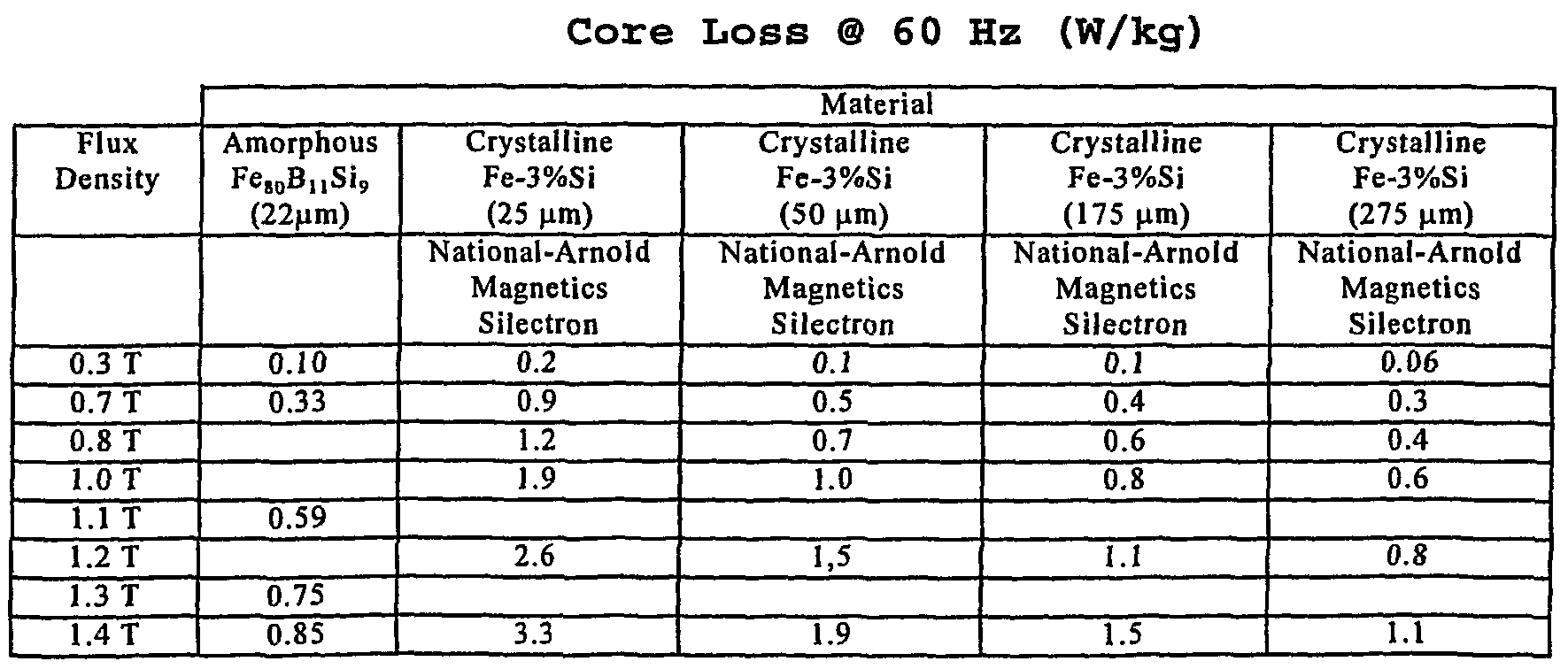
- iron-base amorphous metals preferred for use in the present invention have significantly greater saturation induction than do other low loss soft magnetic materials such as permalloy alloys, whose saturation induction is typically 0.6 - 0.9 T.
- the bulk amorphous metal component can therefore be designed to operate 1) at a lower operating temperature; 2) at higher induction to achieve reduced size and weight; or, 3) at higher excitation frequency to achieve reduced size and weight, or to achieve superior signal resolution, when compared to magnetic components made from other iron-base magnetic metals.
- core loss is that dissipation of energy which occurs
- the core loss of a given magnetic component is generally determined by cyclically
- a time-varying magnetic field is applied to the component to
- Loss is conventionally reported as watts per unit mass or volume of the magnetic material being excited. It is
- poleface magnets ⁇ e.g. ASTM Standards A912-93 and A927(A927M-94) ⁇ call for a
- a component such as a poleface magnet is situated in a magnetically open circuit, i.e. a configuration in which magnetic flux lines must traverse an air gap.
- a given material tested in an open circuit generally exhibits a higher core loss, i.e. a higher value of watts per unit mass or volume, than it would have in a closed-circuit measurement.
- the bulk magnetic component of the invention advantageously exhibits low core loss over a wide range of flux densities and frequencies even in an open-circuit configuration.
- low-loss bulk amorphous metal component of the invention is comprised of
- the invention may be essentially defined by a function having the form
- this formula allows the total core loss of the bulk magnetic component of the invention to be determined at any required operating induction and excitation frequency. It is generally found that in the particular geometry of a bulk magnetic component the magnetic field therein is not spatially uniform. Techniques such as finite element modeling are known in the art to provide an estimate of the spatial and temporal variation of the peak flux density that closely approximates the flux density distribution measured in an actual bulk magnetic component. Using as input a suitable empirical formula giving the magnetic core loss of a given material under spatially uniform flux density these techniques allow the corresponding actual core loss of a
- the magnetic circuit may comprise a
- the flux closure structure means preferably comprises soft magnetic material having
- the soft magnetic material has a
- saturation flux density at least equal to the saturation flux density of the component.
- the flux direction along which the component is to be tested generally defines first
- the flux closure structure means generally comprises a flux closure magnetic component which is constructed preferably in accordance with the present invention but may also be made with other methods and materials known in the art.
- the flux closure magnetic component also has first and second opposing faces through which flux lines enter and emerge, generally normal to the respective planes thereof.
- the flux closure component opposing faces are substantially the same size and shape
- the flux closure magnetic component is placed in
- Magnetomotive force is applied by passing current through a first
- the applied magnetic field is determined by Ampere's law from the
- the core loss is then computed from the applied magnetic field
- FIG. 5 there is illustrated a component 10 having a core loss
- core 70 is appointed as magnetic component 10 for core loss testing.
- the remainder of core 70 serves as the flux closure structure means, which is generally C-shaped and
- each of the cuts 72 which separate the radiused corners 76, the short sides 74, and long side 78a is optional.
- only the cuts separating long side 78b from the remainder of core 70 are made. Cut surfaces formed by cutting core 70 to remove long side 78b define the opposite faces of the magnetic component and the opposite faces of the flux closure magnetic component.
- long side 78b is situated with its faces closely proximate and parallel to the corresponding, faces defined by the cuts.
- the faces of long side 78b are substantially the same in size and shape as the faces of
- magnetic component are generally within the plane of strips 22 and directed
- Fe 80 Bj,Si 9 amorphous metal ribbon approximately 60 mm wide and 0.022 mm thick, was wrapped around a rectangular mandrel or bobbin having dimensions of approximately 25 mm by 90 mm. Approximately 800 wraps of amorphous metal ribbon were wound around the mandrel or bobbin producing a rectangular core form having inner dimensions of approximately 25 mm by 90 mm and a build thickness of
- the core/bobbin assembly was annealed in a nitrogen atmosphere. The anneal consisted of: 1) heating the assembly up to 365° C; 2) holding
- the rectangular, wound, amorphous metal core was
- the core was vacuum impregnated with an
- core/bobbin assembly was cured at 120° C for approximately 4.5 hours.
- a rectangular prism 60 mm long by 40 mm wide by 20 mm thick (approximately 800
- Fe 80 B u Si 9 amorphous metal ribbon approximately 48 mm wide and 0.022 mm thick, was cut into lengths of approximately 300 mm. Approximately 3,800 layers of the cut amorphous metal ribbon were stacked to form a bar approximately 48 mm wide and 300 mm long, with a build thickness of approximately 96 mm.
- the bar was annealed in a nitrogen atmosphere. The anneal consisted of: 1) heating the bar up to 365° C; 2) holding the temperature at approximately 365° C for approximately 2 hours; and, 3) cooling the bar to ambient temperature.
- the bar was vacuum impregnated with an epoxy resin solution and cured at 120° C for approximately 4.5 hours. The resulting stacked, epoxy bonded, amorphous metal bar weighed approximately 9000 g.
- a trapezoidal prism was cut from the stacked, epoxy bonded amorphous metal bar with a 1.5 mm thick cutting blade.
- the trapezoid-shaped face of the prism had
- the trapezoidal prism was 96 mm (3,800
- the core were etched in a nitric acid/water solution and cleaned in an ammonium
- the trapezoidal prism has a core loss of less than 11.5 W/kg when excited at
- the bar was annealed in a nitrogen atmosphere. The anneal consisted of: 1) heating the bar up to 365°C; 2) holding the temperature at approximately 365°C for approximately 2 hours;
- the bar was vacuum impregnated with an epoxy resin solution and cured at 120°C for approximately 4.5 hours.
- the resulting stacked, epoxy bonded, amorphous metal bar weighed approximately 9200 g.
- the stacked, epoxy bonded, amorphous metal bar was cut using electro- discharge machining to form a three-dimensional, arc-shaped block.
- the outer diameter of the block was approximately 96 mm.
- the inner diameter of the block was
- the arc length was approximately 90°.
- the block thickness was approximately 96 mm.
- Fe 80 B n Si 9 amorphous metal ribbon approximately 20 mm wide and 0.022 mm
- the core had a build thickness of approximately 29 mm.
- the core was annealed in a nitrogen atmosphere. The anneal consisted of: 1) heating the bar up to 365°C; 2)
- the core was vacuum impregnated with an
- the wound, epoxy bonded, amorphous metal core was cut using a water jet to form a semi-circular, three dimensional shaped object.
- the semi-circular object had an inner diameter of approximately 19 mm, an outer diameter of approximately 48 mm, and a thickness of approximately 20 mm.
- the cut surfaces of the polygonal, bulk amorphous metal components with arc- shaped cross sections were etched in a nitric acid/water solution and cleaned in an ammonium hydroxide/water solution.
- Each of the polygonal bulk amorphous metal components has a core loss of less
- amorphous metal component comprised of Fe g0 B n Si 9 amorphous metal ribbon could be
- Table 5 recites the measured losses of the component in Example 1 and
- the bar is annealed in a nitrogen atmosphere. The anneal is carried out by performing the
- a rectangular prism is cut from the stacked, epoxy bonded amorphous metal bar with a 1.5 mm thick cutting blade.
- the face of the prism is approximately 25 mm wide and 50 mm long.
- the rectangular prism is 25 mm (1200 layers) thick. The cut
- the rectangular prism has a core loss of less than 11.5 W/kg when excited at
Abstract
Description


Claims
Priority Applications (5)
| Application Number | Priority Date | Filing Date | Title |
|---|---|---|---|
| AU23007/01A AU2300701A (en) | 2000-01-05 | 2001-01-01 | Bulk amorphous metal magnetic component |
| KR1020027008699A KR100733115B1 (en) | 2000-01-05 | 2001-01-03 | Bulk Amorphous Metal Magnetic Component |
| JP2001550766A JP2003519904A (en) | 2000-01-05 | 2001-01-03 | Bulk type amorphous metal magnetic parts |
| EP01900057A EP1245032A1 (en) | 2000-01-05 | 2001-01-03 | Bulk amorphous metal magnetic component |
| HK04106167.0A HK1063529A1 (en) | 2000-01-05 | 2004-08-17 | Bulk amorphous metal magnetic component |
Applications Claiming Priority (2)
| Application Number | Priority Date | Filing Date | Title |
|---|---|---|---|
| US09/477,905 US6346337B1 (en) | 1998-11-06 | 2000-01-05 | Bulk amorphous metal magnetic component |
| US09/477,905 | 2000-01-05 |
Publications (1)
| Publication Number | Publication Date |
|---|---|
| WO2001050483A1 true WO2001050483A1 (en) | 2001-07-12 |
Family
ID=23897807
Family Applications (1)
| Application Number | Title | Priority Date | Filing Date |
|---|---|---|---|
| PCT/US2001/000099 WO2001050483A1 (en) | 2000-01-05 | 2001-01-03 | Bulk amorphous metal magnetic component |
Country Status (9)
| Country | Link |
|---|---|
| US (1) | US6346337B1 (en) |
| EP (1) | EP1245032A1 (en) |
| JP (2) | JP2003519904A (en) |
| KR (1) | KR100733115B1 (en) |
| CN (1) | CN100483573C (en) |
| AU (1) | AU2300701A (en) |
| HK (1) | HK1063529A1 (en) |
| TW (1) | TW503407B (en) |
| WO (1) | WO2001050483A1 (en) |
Cited By (7)
| Publication number | Priority date | Publication date | Assignee | Title |
|---|---|---|---|---|
| US6737951B1 (en) | 2002-11-01 | 2004-05-18 | Metglas, Inc. | Bulk amorphous metal inductive device |
| WO2004042746A3 (en) * | 2002-11-01 | 2004-07-01 | Metglas Inc | Bulk laminated amorphous metal inductive device |
| US7235910B2 (en) | 2003-04-25 | 2007-06-26 | Metglas, Inc. | Selective etching process for cutting amorphous metal shapes and components made thereof |
| SG132550A1 (en) * | 2005-12-02 | 2007-06-28 | Sony Corp | Magnetic structures, methods of fabricating magnetic structures and micro-devices incorporating such magnetic structures |
| WO2008032274A2 (en) * | 2006-09-13 | 2008-03-20 | Megasec Ltd. | Magneto-mechanical markers for use in article surveilance system |
| JP2009224800A (en) * | 2003-06-23 | 2009-10-01 | Imphy Alloys | Method for manufacturing component for passive electronic element and component obtained by it |
| WO2010082195A1 (en) | 2009-01-13 | 2010-07-22 | Vladimir Manov | Magnetomechanical markers and magnetostrictive amorphous element for use therein |
Families Citing this family (22)
| Publication number | Priority date | Publication date | Assignee | Title |
|---|---|---|---|---|
| US6462456B1 (en) * | 1998-11-06 | 2002-10-08 | Honeywell International Inc. | Bulk amorphous metal magnetic components for electric motors |
| US6803694B2 (en) * | 1998-11-06 | 2004-10-12 | Metglas, Inc. | Unitary amorphous metal component for an axial flux electric machine |
| US7011718B2 (en) * | 2001-04-25 | 2006-03-14 | Metglas, Inc. | Bulk stamped amorphous metal magnetic component |
| US6737784B2 (en) * | 2000-10-16 | 2004-05-18 | Scott M. Lindquist | Laminated amorphous metal component for an electric machine |
| US7061355B2 (en) * | 2002-08-30 | 2006-06-13 | Hitachi Metals, Ltd. | Ferrite core, CATV equipment and bi-directional CATV system |
| US7144468B2 (en) * | 2002-09-05 | 2006-12-05 | Metglas, Inc. | Method of constructing a unitary amorphous metal component for an electric machine |
| US6784588B2 (en) * | 2003-02-03 | 2004-08-31 | Metglas, Inc. | Low core loss amorphous metal magnetic components for electric motors |
| US7596856B2 (en) * | 2003-06-11 | 2009-10-06 | Light Engineering, Inc. | Method for manufacturing a soft magnetic metal electromagnetic component |
| CN100490028C (en) * | 2005-12-07 | 2009-05-20 | 安泰科技股份有限公司 | Block-shaped soft magnetic alloy lamination element and its manufacturing method |
| JP2008071982A (en) * | 2006-09-15 | 2008-03-27 | Hitachi Industrial Equipment Systems Co Ltd | Transformer |
| FI122085B (en) * | 2007-12-04 | 2011-08-15 | Vacon Oyj | Suotokuristinjärjestely |
| US8456807B2 (en) * | 2010-07-16 | 2013-06-04 | Rockwell Automation Technologies, Inc. | Common mode magnetic device for bus structure |
| CN105730717A (en) * | 2014-12-09 | 2016-07-06 | 上海新跃仪表厂 | Miniature magnetic torquer and manufacturing method for amorphous bar of miniature magnetic torquer |
| CN105743232B (en) * | 2014-12-09 | 2019-11-05 | 上海新跃仪表厂 | The manufacturing method of Miniature magnetic torquer and its amorphous bar |
| JP6589564B2 (en) * | 2015-11-02 | 2019-10-16 | 日本製鉄株式会社 | Amorphous laminated core and method for producing amorphous laminated core |
| CN108987092B (en) * | 2018-08-17 | 2021-08-24 | 佛山市中研非晶科技股份有限公司 | Method for manufacturing block-shaped amorphous alloy laminated element |
| CN110079750B (en) * | 2019-04-26 | 2020-10-02 | 北京科技大学 | Low-melting-point nickel-based amorphous nanocrystalline alloy and preparation method thereof |
| RU201014U1 (en) * | 2020-03-24 | 2020-11-23 | Юрий Пантелеевич Лепеха | ELECTROMAGNETIC INTERFERENCE FILTER |
| CN111478530A (en) * | 2020-06-01 | 2020-07-31 | 苏州英磁新能源科技有限公司 | Manufacturing process of radial flux cylinder type motor iron core |
| RU202390U1 (en) * | 2020-11-26 | 2021-02-16 | Юрий Пантелеевич Лепеха | DC INTERFERENCE FILTER, MODULAR |
| CN115036125B (en) * | 2022-06-27 | 2023-05-09 | 中国科学院空间应用工程与技术中心 | Nanocrystalline magnetic core, preparation method thereof and magnetic equipment |
| CN115247243B (en) * | 2022-08-24 | 2023-06-27 | 盘星新型合金材料(常州)有限公司 | Hf-containing light large-size block amorphous alloy and preparation method and application thereof |
Citations (6)
| Publication number | Priority date | Publication date | Assignee | Title |
|---|---|---|---|---|
| JPS58148419A (en) * | 1982-02-27 | 1983-09-03 | Matsushita Electric Works Ltd | Manufacture of amorphous core |
| JPS58148418A (en) * | 1982-02-27 | 1983-09-03 | Matsushita Electric Works Ltd | Manufacture of cut core |
| JPS59181504A (en) * | 1983-03-31 | 1984-10-16 | Toshiba Corp | Constant permeability core |
| JPS61131518A (en) * | 1984-11-30 | 1986-06-19 | Toshiba Corp | Manufacture of amorphous core |
| WO1994014994A1 (en) * | 1992-12-23 | 1994-07-07 | Alliedsignal Inc. | AMORPHOUS Fe-B-Si-C ALLOYS HAVING SOFT MAGNETIC CHARACTERISTICS USEFUL IN LOW FREQUENCY APPLICATIONS |
| WO2000028556A1 (en) * | 1998-11-06 | 2000-05-18 | Honeywell International Inc. | Bulk amorphous metal magnetic components |
Family Cites Families (26)
| Publication number | Priority date | Publication date | Assignee | Title |
|---|---|---|---|---|
| US4226619A (en) | 1979-05-04 | 1980-10-07 | Electric Power Research Institute, Inc. | Amorphous alloy with high magnetic induction at room temperature |
| US4219355A (en) | 1979-05-25 | 1980-08-26 | Allied Chemical Corporation | Iron-metalloid amorphous alloys for electromagnetic devices |
| US4298409A (en) | 1979-12-10 | 1981-11-03 | Allied Chemical Corporation | Method for making iron-metalloid amorphous alloys for electromagnetic devices |
| JPS6034620B2 (en) | 1981-03-06 | 1985-08-09 | 新日本製鐵株式会社 | Amorphous alloy with extremely low iron loss and good thermal stability |
| EP0161782B1 (en) | 1984-04-11 | 1988-11-09 | Sumitomo Special Metal Co., Ltd. | Magnetic field generating device for nmr-ct |
| US4734975A (en) * | 1985-12-04 | 1988-04-05 | General Electric Company | Method of manufacturing an amorphous metal transformer core and coil assembly |
| JPS6313306A (en) | 1986-07-04 | 1988-01-20 | Hitachi Ltd | Electromagnet iron core and manufacture thereof |
| US4827235A (en) | 1986-07-18 | 1989-05-02 | Kabushiki Kaisha Toshiba | Magnetic field generator useful for a magnetic resonance imaging instrument |
| US4766378A (en) | 1986-11-28 | 1988-08-23 | Fonar Corporation | Nuclear magnetic resonance scanners |
| JPS63241905A (en) | 1987-03-27 | 1988-10-07 | Sumitomo Special Metals Co Ltd | Magnetic field generating equipment |
| US4892773A (en) * | 1987-07-30 | 1990-01-09 | Westinghouse Electric Corp. | Preparation of amorphous metal core for use in transformer |
| US5061897A (en) | 1990-03-23 | 1991-10-29 | Fonar Corporation | Eddy current control in magnetic resonance imaging |
| DE69129687T2 (en) | 1990-09-29 | 1999-03-11 | Sumitomo Spec Metals | Device for generating a magnetic field for imaging by means of magnetic resonance |
| US5124651A (en) | 1990-10-24 | 1992-06-23 | Fonar Corporation | Nuclear magnetic resonance scanners with composite pole facings |
| US5134771A (en) * | 1991-07-05 | 1992-08-04 | General Electric Company | Method for manufacturing and amorphous metal core for a transformer that includes steps for reducing core loss |
| US5754085A (en) | 1992-09-28 | 1998-05-19 | Fonar Corporation | Ferromagnetic yoke magnets for medical magnetic resonance studies |
| WO1995021044A1 (en) | 1994-02-01 | 1995-08-10 | A.M.D. International Pty. Ltd. | Cutting cores from amorphous material by non corrosive liquids and abrasives |
| AUPM644394A0 (en) | 1994-06-24 | 1994-07-21 | Electro Research International Pty Ltd | Bulk metallic glass motor and transformer parts and method of manufacture |
| US5495222A (en) | 1994-04-15 | 1996-02-27 | New York University | Open permanent magnet structure for generating highly uniform field |
| US5798680A (en) | 1994-04-15 | 1998-08-25 | New York University | Strapped open magnetic structure |
| AU2440795A (en) | 1994-05-13 | 1996-01-04 | Global Future Energy Pty Ltd | Modular electric machines |
| DE69633683T2 (en) | 1995-08-28 | 2006-03-09 | Shin-Etsu Chemical Co., Ltd. | Magnetic circuit arrangement with opposing permanent magnets |
| US7057489B2 (en) * | 1997-08-21 | 2006-06-06 | Metglas, Inc. | Segmented transformer core |
| US6150818A (en) | 1998-08-31 | 2000-11-21 | General Electric Company | Low eddy current and low hysteresis magnet pole faces in MR imaging |
| US6259252B1 (en) | 1998-11-24 | 2001-07-10 | General Electric Company | Laminate tile pole piece for an MRI, a method manufacturing the pole piece and a mold bonding pole piece tiles |
| US6150819A (en) | 1998-11-24 | 2000-11-21 | General Electric Company | Laminate tiles for an MRI system and method and apparatus for manufacturing the laminate tiles |
-
2000
- 2000-01-05 US US09/477,905 patent/US6346337B1/en not_active Expired - Lifetime
-
2001
- 2001-01-01 AU AU23007/01A patent/AU2300701A/en not_active Abandoned
- 2001-01-03 KR KR1020027008699A patent/KR100733115B1/en not_active IP Right Cessation
- 2001-01-03 WO PCT/US2001/000099 patent/WO2001050483A1/en active Application Filing
- 2001-01-03 EP EP01900057A patent/EP1245032A1/en not_active Withdrawn
- 2001-01-03 JP JP2001550766A patent/JP2003519904A/en active Pending
- 2001-01-03 CN CNB01806129XA patent/CN100483573C/en not_active Expired - Fee Related
- 2001-01-16 TW TW090100320A patent/TW503407B/en not_active IP Right Cessation
-
2004
- 2004-08-17 HK HK04106167.0A patent/HK1063529A1/en not_active IP Right Cessation
-
2005
- 2005-01-13 JP JP2005005905A patent/JP4865231B2/en not_active Expired - Fee Related
Patent Citations (6)
| Publication number | Priority date | Publication date | Assignee | Title |
|---|---|---|---|---|
| JPS58148419A (en) * | 1982-02-27 | 1983-09-03 | Matsushita Electric Works Ltd | Manufacture of amorphous core |
| JPS58148418A (en) * | 1982-02-27 | 1983-09-03 | Matsushita Electric Works Ltd | Manufacture of cut core |
| JPS59181504A (en) * | 1983-03-31 | 1984-10-16 | Toshiba Corp | Constant permeability core |
| JPS61131518A (en) * | 1984-11-30 | 1986-06-19 | Toshiba Corp | Manufacture of amorphous core |
| WO1994014994A1 (en) * | 1992-12-23 | 1994-07-07 | Alliedsignal Inc. | AMORPHOUS Fe-B-Si-C ALLOYS HAVING SOFT MAGNETIC CHARACTERISTICS USEFUL IN LOW FREQUENCY APPLICATIONS |
| WO2000028556A1 (en) * | 1998-11-06 | 2000-05-18 | Honeywell International Inc. | Bulk amorphous metal magnetic components |
Non-Patent Citations (4)
| Title |
|---|
| G.E.FISH: "High permeability iron-based metallic glasses for line frequency applications", JOURNAL OF APPLIED PHYSICS., vol. 57, no. 1, 15 April 1985 (1985-04-15), AMERICAN INSTITUTE OF PHYSICS. NEW YORK., US, pages 3569 - 3571, XP000990110, ISSN: 0021-8979 * |
| PATENT ABSTRACTS OF JAPAN vol. 007, no. 267 (E - 213) 29 November 1983 (1983-11-29) * |
| PATENT ABSTRACTS OF JAPAN vol. 009, no. 039 (E - 297) 19 February 1985 (1985-02-19) * |
| PATENT ABSTRACTS OF JAPAN vol. 010, no. 319 (E - 450) 30 October 1986 (1986-10-30) * |
Cited By (11)
| Publication number | Priority date | Publication date | Assignee | Title |
|---|---|---|---|---|
| US6737951B1 (en) | 2002-11-01 | 2004-05-18 | Metglas, Inc. | Bulk amorphous metal inductive device |
| WO2004042746A3 (en) * | 2002-11-01 | 2004-07-01 | Metglas Inc | Bulk laminated amorphous metal inductive device |
| US6873239B2 (en) | 2002-11-01 | 2005-03-29 | Metglas Inc. | Bulk laminated amorphous metal inductive device |
| US7289013B2 (en) | 2002-11-01 | 2007-10-30 | Metglas, Inc. | Bulk amorphous metal inductive device |
| US7235910B2 (en) | 2003-04-25 | 2007-06-26 | Metglas, Inc. | Selective etching process for cutting amorphous metal shapes and components made thereof |
| JP2009224800A (en) * | 2003-06-23 | 2009-10-01 | Imphy Alloys | Method for manufacturing component for passive electronic element and component obtained by it |
| US8362361B2 (en) | 2003-06-23 | 2013-01-29 | Imphy Alloys | Method for producing parts for passive electronic components and parts produced |
| SG132550A1 (en) * | 2005-12-02 | 2007-06-28 | Sony Corp | Magnetic structures, methods of fabricating magnetic structures and micro-devices incorporating such magnetic structures |
| WO2008032274A2 (en) * | 2006-09-13 | 2008-03-20 | Megasec Ltd. | Magneto-mechanical markers for use in article surveilance system |
| WO2008032274A3 (en) * | 2006-09-13 | 2008-08-28 | Megasec Ltd | Magneto-mechanical markers for use in article surveilance system |
| WO2010082195A1 (en) | 2009-01-13 | 2010-07-22 | Vladimir Manov | Magnetomechanical markers and magnetostrictive amorphous element for use therein |
Also Published As
| Publication number | Publication date |
|---|---|
| JP2005191583A (en) | 2005-07-14 |
| EP1245032A1 (en) | 2002-10-02 |
| US6346337B1 (en) | 2002-02-12 |
| AU2300701A (en) | 2001-07-16 |
| HK1063529A1 (en) | 2004-12-31 |
| CN100483573C (en) | 2009-04-29 |
| KR20030007393A (en) | 2003-01-23 |
| KR100733115B1 (en) | 2007-06-27 |
| TW503407B (en) | 2002-09-21 |
| JP4865231B2 (en) | 2012-02-01 |
| JP2003519904A (en) | 2003-06-24 |
| CN1476617A (en) | 2004-02-18 |
Similar Documents
| Publication | Publication Date | Title |
|---|---|---|
| US6346337B1 (en) | Bulk amorphous metal magnetic component | |
| US6462456B1 (en) | Bulk amorphous metal magnetic components for electric motors | |
| US6960860B1 (en) | Amorphous metal stator for a radial-flux electric motor | |
| US6348275B1 (en) | Bulk amorphous metal magnetic component | |
| US7506566B2 (en) | Bulk stamped amorphous metal magnetic component | |
| US6737951B1 (en) | Bulk amorphous metal inductive device | |
| EP1127359B1 (en) | Bulk amorphous metal magnetic components | |
| JP5394411B2 (en) | Punched bulk amorphous metal magnetic parts | |
| US7235910B2 (en) | Selective etching process for cutting amorphous metal shapes and components made thereof | |
| US20030201864A1 (en) | High performance bulk metal magnetic component |
Legal Events
| Date | Code | Title | Description |
|---|---|---|---|
| AK | Designated states |
Kind code of ref document: A1 Designated state(s): AE AL AM AT AU AZ BA BB BG BR BY CA CH CN CR CU CZ DE DK DM EE ES FI GB GD GE GH GM HR HU ID IL IN IS JP KE KG KP KR KZ LC LK LR LS LT LU LV MA MD MG MK MN MW MX NO NZ PL PT RO RU SD SE SG SI SK SL TJ TM TR TT TZ UA UG UZ VN YU ZA ZW |
|
| AL | Designated countries for regional patents |
Kind code of ref document: A1 Designated state(s): GH GM KE LS MW MZ SD SL SZ TZ UG ZW AM AZ BY KG KZ MD RU TJ TM AT BE CH CY DE DK ES FI FR GB GR IE IT LU MC NL PT SE TR BF BJ CF CG CI CM GA GN GW ML MR NE SN TD TG |
|
| 121 | Ep: the epo has been informed by wipo that ep was designated in this application | ||
| DFPE | Request for preliminary examination filed prior to expiration of 19th month from priority date (pct application filed before 20040101) | ||
| WWE | Wipo information: entry into national phase |
Ref document number: 2001900057 Country of ref document: EP |
|
| WWE | Wipo information: entry into national phase |
Ref document number: 1020027008699 Country of ref document: KR Ref document number: IN/PCT/2002/00666/DE Country of ref document: IN |
|
| ENP | Entry into the national phase |
Ref document number: 2001 550766 Country of ref document: JP Kind code of ref document: A |
|
| WWE | Wipo information: entry into national phase |
Ref document number: 01806129X Country of ref document: CN |
|
| WWP | Wipo information: published in national office |
Ref document number: 2001900057 Country of ref document: EP |
|
| REG | Reference to national code |
Ref country code: DE Ref legal event code: 8642 |
|
| WWP | Wipo information: published in national office |
Ref document number: 1020027008699 Country of ref document: KR |