USRE682E - Improved tubular elastic valve - Google Patents
Improved tubular elastic valve Download PDFInfo
- Publication number
- USRE682E USRE682E US RE682 E USRE682 E US RE682E
- Authority
- US
- United States
- Prior art keywords
- elastic valve
- valve
- tubular elastic
- valves
- improved tubular
- Prior art date
Links
- 239000000463 material Substances 0.000 description 22
- 238000010276 construction Methods 0.000 description 6
- WTEVQBCEXWBHNA-YFHOEESVSA-N neral Chemical compound CC(C)=CCC\C(C)=C/C=O WTEVQBCEXWBHNA-YFHOEESVSA-N 0.000 description 4
- 206010037833 Rales Diseases 0.000 description 2
- 241001473780 Sideroxylon lanuginosum Species 0.000 description 2
- 230000001070 adhesive Effects 0.000 description 2
- 239000000853 adhesive Substances 0.000 description 2
- WTEVQBCEXWBHNA-JXMROGBWSA-N citral A Natural products CC(C)=CCC\C(C)=C\C=O WTEVQBCEXWBHNA-JXMROGBWSA-N 0.000 description 2
- 239000012530 fluid Substances 0.000 description 2
- 238000004519 manufacturing process Methods 0.000 description 2
- 239000002184 metal Substances 0.000 description 2
Images
Definitions
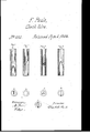
- They A may be-constructed of the same materials as the tubes or pipes in which they are placed, either in the original fabrica tion or in parts ⁇ by adhesive cementsof the same base ⁇ or component parts, as maybe found most convenient or practicable; or they may be attached in any -way desired to rigid tubes of any descriptionin which they can be Figure 1, letter a Iof the drawing represents a longitudinalsectionv'of what may be. V called the vein-valve, and letter b a crosssection of the same.
- the rst exhibits -a side view of the valve closed, and' is intended to be'made by aduplicati'on of the flexible material, reduced in thickness so as to yield ⁇ readily to theupward passage of iiuids op'erated upon, and to close as readily and prevent their passage downward'or in a reversed direction.
- the drawing represents a pocket, double, one on each side of the walls of the passage, 'whose thin, flexible edges lietogether, but permitting the pas- Vsage of fluids in one direction and arrestingythe flow in the other.
- Letterb ot' the same figure exhibits the position of the valve as if 'closedfand seen from above.
- letter-a represents a longitudinal -section of a single arterial valve with one flexible pocket constructed of ⁇ the same materials as the walls of tlieftubel in its original construction, or cemented' in, '-and, like the preceding, is a duplication of 'the exiblema- "tcrial/ opening freely-to the-passage of uids in one direction and closing as freely in the opposite.
- Letter b o'f Fig.2 ⁇ is a representa- ⁇ April 5, 1859. l
- V Fig. 3 represents a triplicate or threefold construction of the lsame general form and operating in the same manner as'the preceding, letter b of vthat gure representing the manner in which the thin,ilexib1e edges liel in contact and operate in permitting or arresting the flow, according to its direction.
- Fig. 4 represents what may be called a splice-valve, constructed upon the same ge'neral principles 'by dividing theV walls of the tube in aA sloping direction to the middle from -each side and inserting plates of theleXible or elastic material and cementing them to the Walls of the tube, leaving their upper edges in contact, but at liberty to expand when 'requisite for the flow of iiuids in one direction, and arresting it in the opposite direction.
- same figure exhibit the appearance of the valvcsfrom above, the trst closed, thclart open.
- valves in each of the abovecascs caneither be constructed of the lining material or'nterior of the tube, or they can be constructed of any exible material and inserted -in the tube', the feature of my improvement being theemployment of valves composed of ilexiblc .materials arranged so as to open in one direction by the elastic or flexible quality of the .material composing the valve, and to close again by reason lof the same propertya Heretibre vin pumps, syringes, and other in struments 'constructed of iexible materials, it has vb een customary to make valves -of metal and insert .them in the course of the flexible tube but' this is attended with some gexpense, and such valves are liable' ⁇ to, be-
Description
` employed.
U N'I'TED x STATES PATENT l ERANKLIN raLE, on PHILADELPHIA, ress sYLVAJNLA iMPaovl-:D TUBULAR ELAsTlc- VALVE.
' specification forming partof Lettersratent No. 15,192, dated .inne l24, 1856; Reissue No. cs2, dated To all whom it may concern' .l Be it known that I, FRANKLIN PEALE, of
'the 'eonsolidated'city and countyv of Philadel whether s uch instruments be of rigid or Ilexible materials, including gum-elastic and its combinations, of which the following is a speciieation. y
The-construction of these valves and their "operationare intended tdimitate as nearly as may be the valves of the arterial and other portions of the human organization, being the simplest andlbest. adapted tothe objects A in view.,7 They Amay be-constructed of the same materials as the tubes or pipes in which they are placed, either in the original fabrica tion or in parts` by adhesive cementsof the same base `or component parts, as maybe found most convenient or practicable; or they may be attached in any -way desired to rigid tubes of any descriptionin which they can be Figure 1, letter a Iof the drawing represents a longitudinalsectionv'of what may be. V called the vein-valve, and letter b a crosssection of the same. The rst exhibits -a side view of the valve closed, and' is intended to be'made by aduplicati'on of the flexible material, reduced in thickness so as to yield` readily to theupward passage of iiuids op'erated upon, and to close as readily and prevent their passage downward'or in a reversed direction. Or, in other. words, the drawing represents a pocket, double, one on each side of the walls of the passage, 'whose thin, flexible edges lietogether, but permitting the pas- Vsage of fluids in one direction and arrestingythe flow in the other. Letterb ot' the same figure exhibits the position of the valve as if 'closedfand seen from above.
Fig. 2, letter-a represents a longitudinal -section of a single arterial valve with one flexible pocket constructed of `the same materials as the walls of tlieftubel in its original construction, or cemented' in, '-and, like the preceding, is a duplication of 'the exiblema- "tcrial/ opening freely-to the-passage of uids in one direction and closing as freely in the opposite. Letter b o'f Fig.2`is a representa-` April 5, 1859. l
tion of the valve-'closed by a cross-scetion, seen from above. V Fig. 3 represents a triplicate or threefold construction of the lsame general form and operating in the same manner as'the preceding, letter b of vthat gure representing the manner in which the thin,ilexib1e edges liel in contact and operate in permitting or arresting the flow, according to its direction.
\ Fig. 4 represents what may be called a splice-valve, constructed upon the same ge'neral principles 'by dividing theV walls of the tube in aA sloping direction to the middle from -each side and inserting plates of theleXible or elastic material and cementing them to the Walls of the tube, leaving their upper edges in contact, but at liberty to expand when 'requisite for the flow of iiuids in one direction, and arresting it in the opposite direction. same figure exhibit the appearance of the valvcsfrom above, the trst closed, thclart open.
The valves in each of the abovecascs caneither be constructed of the lining material or'nterior of the tube, or they can be constructed of any exible material and inserted -in the tube', the feature of my improvement being theemployment of valves composed of ilexiblc .materials arranged so as to open in one direction by the elastic or flexible quality of the .material composing the valve, and to close again by reason lof the same propertya Heretibre vin pumps, syringes, and other in struments 'constructed of iexible materials, it has vb een customary to make valves -of metal and insert .them in the course of the flexible tube but' this is attended with some gexpense, and such valves are liable' `to, be-
come deranged readily and to losetheir.,
shape by-any pressure brought upon the outside of thetube or valve-seat. My improved valves, being 'made of a duplicature di' the flexible lining or interior of the tube,'or of similar material insertedtherein, are not liable to deran gemen t. They yield to pressure and immediately .resumetheir proper form and position. They act equally well,noA matter in what position .they may be placed. They canbe manufactured at a very triingcost comf Vpared to metallicfvalves, and they are very effective.v 4 p.
The horizontal sections b and c ot' the.
2 l veem Having thus described my improved valves, tubes of any kind, Whether rigid. or elastic, what I claim as ymy invention, and desire to and inserting them therein in the manner srt secure by Letters Patent, is forth and shown, or in any equivalent mode. 1. The exible valves herein described, for FRANKLIN PEALE.
the purposes specified. Witnesses:
` 2. The method herein deseribed of adapt- ALEX. G. GAW,
ing the seid flexible valves to pump or other BENJ. DAVIS.
Family
ID=
Similar Documents
| Publication | Publication Date | Title |
|---|---|---|
| US15192A (en) | Tubular | |
| USRE682E (en) | Improved tubular elastic valve | |
| US22080A (en) | Bkeast-pipe | |
| US25154A (en) | Julius wehle | |
| US21381A (en) | Bracelet | |
| US28375A (en) | John k | |
| US23950A (en) | Clock-dial | |
| US1095930A (en) | Bellows suction-pump. | |
| US23658A (en) | Faucet | |
| US482185A (en) | milsted | |
| US68629A (en) | Thomas lewis | |
| US469593A (en) | George w | |
| US1191748A (en) | Puff-retaining ring. | |
| DE714232C (en) | Injection ampoule | |
| US19177A (en) | Moses m | |
| US20848A (en) | grimes | |
| US85652A (en) | Improvement in corn-planters | |
| US82577A (en) | Improvement in pocket-book fastenings | |
| US503164A (en) | Mariner s compass | |
| US23506A (en) | Island | |
| USD3224S (en) | Design for a clock-case | |
| US702199A (en) | Eyelet. | |
| US84558A (en) | Improvement in watch-keys | |
| US67056A (en) | Willtam h | |
| US83824A (en) | Improvement in sash-fastener |