US9951675B2 - Structure of intercooler cover integrated into fan shroud for turbocharged engine and method for operating the same - Google Patents
Structure of intercooler cover integrated into fan shroud for turbocharged engine and method for operating the same Download PDFInfo
- Publication number
- US9951675B2 US9951675B2 US14/926,906 US201514926906A US9951675B2 US 9951675 B2 US9951675 B2 US 9951675B2 US 201514926906 A US201514926906 A US 201514926906A US 9951675 B2 US9951675 B2 US 9951675B2
- Authority
- US
- United States
- Prior art keywords
- intercooler
- side portion
- ventilator
- vehicle
- cooling module
- Prior art date
- Legal status (The legal status is an assumption and is not a legal conclusion. Google has not performed a legal analysis and makes no representation as to the accuracy of the status listed.)
- Active, expires
Links
Images


Classifications
-
- B—PERFORMING OPERATIONS; TRANSPORTING
- B60—VEHICLES IN GENERAL
- B60K—ARRANGEMENT OR MOUNTING OF PROPULSION UNITS OR OF TRANSMISSIONS IN VEHICLES; ARRANGEMENT OR MOUNTING OF PLURAL DIVERSE PRIME-MOVERS IN VEHICLES; AUXILIARY DRIVES FOR VEHICLES; INSTRUMENTATION OR DASHBOARDS FOR VEHICLES; ARRANGEMENTS IN CONNECTION WITH COOLING, AIR INTAKE, GAS EXHAUST OR FUEL SUPPLY OF PROPULSION UNITS IN VEHICLES
- B60K13/00—Arrangement in connection with combustion air intake or gas exhaust of propulsion units
- B60K13/02—Arrangement in connection with combustion air intake or gas exhaust of propulsion units concerning intake
-
- F—MECHANICAL ENGINEERING; LIGHTING; HEATING; WEAPONS; BLASTING
- F01—MACHINES OR ENGINES IN GENERAL; ENGINE PLANTS IN GENERAL; STEAM ENGINES
- F01P—COOLING OF MACHINES OR ENGINES IN GENERAL; COOLING OF INTERNAL-COMBUSTION ENGINES
- F01P7/00—Controlling of coolant flow
- F01P7/02—Controlling of coolant flow the coolant being cooling-air
-
- B—PERFORMING OPERATIONS; TRANSPORTING
- B60—VEHICLES IN GENERAL
- B60K—ARRANGEMENT OR MOUNTING OF PROPULSION UNITS OR OF TRANSMISSIONS IN VEHICLES; ARRANGEMENT OR MOUNTING OF PLURAL DIVERSE PRIME-MOVERS IN VEHICLES; AUXILIARY DRIVES FOR VEHICLES; INSTRUMENTATION OR DASHBOARDS FOR VEHICLES; ARRANGEMENTS IN CONNECTION WITH COOLING, AIR INTAKE, GAS EXHAUST OR FUEL SUPPLY OF PROPULSION UNITS IN VEHICLES
- B60K11/00—Arrangement in connection with cooling of propulsion units
- B60K11/02—Arrangement in connection with cooling of propulsion units with liquid cooling
- B60K11/04—Arrangement or mounting of radiators, radiator shutters, or radiator blinds
-
- B—PERFORMING OPERATIONS; TRANSPORTING
- B60—VEHICLES IN GENERAL
- B60K—ARRANGEMENT OR MOUNTING OF PROPULSION UNITS OR OF TRANSMISSIONS IN VEHICLES; ARRANGEMENT OR MOUNTING OF PLURAL DIVERSE PRIME-MOVERS IN VEHICLES; AUXILIARY DRIVES FOR VEHICLES; INSTRUMENTATION OR DASHBOARDS FOR VEHICLES; ARRANGEMENTS IN CONNECTION WITH COOLING, AIR INTAKE, GAS EXHAUST OR FUEL SUPPLY OF PROPULSION UNITS IN VEHICLES
- B60K11/00—Arrangement in connection with cooling of propulsion units
- B60K11/08—Air inlets for cooling; Shutters or blinds therefor
- B60K11/085—Air inlets for cooling; Shutters or blinds therefor with adjustable shutters or blinds
-
- F—MECHANICAL ENGINEERING; LIGHTING; HEATING; WEAPONS; BLASTING
- F01—MACHINES OR ENGINES IN GENERAL; ENGINE PLANTS IN GENERAL; STEAM ENGINES
- F01P—COOLING OF MACHINES OR ENGINES IN GENERAL; COOLING OF INTERNAL-COMBUSTION ENGINES
- F01P1/00—Air cooling
- F01P1/06—Arrangements for cooling other engine or machine parts
-
- F—MECHANICAL ENGINEERING; LIGHTING; HEATING; WEAPONS; BLASTING
- F01—MACHINES OR ENGINES IN GENERAL; ENGINE PLANTS IN GENERAL; STEAM ENGINES
- F01P—COOLING OF MACHINES OR ENGINES IN GENERAL; COOLING OF INTERNAL-COMBUSTION ENGINES
- F01P3/00—Liquid cooling
- F01P3/18—Arrangements or mounting of liquid-to-air heat-exchangers
-
- F—MECHANICAL ENGINEERING; LIGHTING; HEATING; WEAPONS; BLASTING
- F01—MACHINES OR ENGINES IN GENERAL; ENGINE PLANTS IN GENERAL; STEAM ENGINES
- F01P—COOLING OF MACHINES OR ENGINES IN GENERAL; COOLING OF INTERNAL-COMBUSTION ENGINES
- F01P5/00—Pumping cooling-air or liquid coolants
- F01P5/02—Pumping cooling-air; Arrangements of cooling-air pumps, e.g. fans or blowers
-
- F—MECHANICAL ENGINEERING; LIGHTING; HEATING; WEAPONS; BLASTING
- F02—COMBUSTION ENGINES; HOT-GAS OR COMBUSTION-PRODUCT ENGINE PLANTS
- F02B—INTERNAL-COMBUSTION PISTON ENGINES; COMBUSTION ENGINES IN GENERAL
- F02B29/00—Engines characterised by provision for charging or scavenging not provided for in groups F02B25/00, F02B27/00 or F02B33/00 - F02B39/00; Details thereof
- F02B29/04—Cooling of air intake supply
-
- F—MECHANICAL ENGINEERING; LIGHTING; HEATING; WEAPONS; BLASTING
- F01—MACHINES OR ENGINES IN GENERAL; ENGINE PLANTS IN GENERAL; STEAM ENGINES
- F01P—COOLING OF MACHINES OR ENGINES IN GENERAL; COOLING OF INTERNAL-COMBUSTION ENGINES
- F01P3/00—Liquid cooling
- F01P3/18—Arrangements or mounting of liquid-to-air heat-exchangers
- F01P2003/185—Arrangements or mounting of liquid-to-air heat-exchangers arranged in parallel
-
- F—MECHANICAL ENGINEERING; LIGHTING; HEATING; WEAPONS; BLASTING
- F01—MACHINES OR ENGINES IN GENERAL; ENGINE PLANTS IN GENERAL; STEAM ENGINES
- F01P—COOLING OF MACHINES OR ENGINES IN GENERAL; COOLING OF INTERNAL-COMBUSTION ENGINES
- F01P2060/00—Cooling circuits using auxiliaries
- F01P2060/02—Intercooler
-
- Y—GENERAL TAGGING OF NEW TECHNOLOGICAL DEVELOPMENTS; GENERAL TAGGING OF CROSS-SECTIONAL TECHNOLOGIES SPANNING OVER SEVERAL SECTIONS OF THE IPC; TECHNICAL SUBJECTS COVERED BY FORMER USPC CROSS-REFERENCE ART COLLECTIONS [XRACs] AND DIGESTS
- Y02—TECHNOLOGIES OR APPLICATIONS FOR MITIGATION OR ADAPTATION AGAINST CLIMATE CHANGE
- Y02T—CLIMATE CHANGE MITIGATION TECHNOLOGIES RELATED TO TRANSPORTATION
- Y02T10/00—Road transport of goods or passengers
- Y02T10/80—Technologies aiming to reduce greenhouse gasses emissions common to all road transportation technologies
- Y02T10/88—Optimized components or subsystems, e.g. lighting, actively controlled glasses
Definitions
- the present disclosure relates to a structure of an intercooler cover integrated into a fan shroud for a vehicle engine, and a method for operating the same, capable of improving efficiency of a conventional air-cooled intercooler.
- a vehicle having a turbo engine has been rapidly increased for downsizing an engine and improving fuel consumption.
- Performance (such as engine output and fuel consumption) of the turbo engine is influenced by a cooling efficiency of an intercooler. Therefore, the cooling efficiency of the intercooler is a significant factor of vehicle performance.
- the cooling efficiency of the intercooler is improved, the engine output and the fuel consumption may improve as a charging efficiency increases.
- FIGS. 1-3 illustrate a structure of an intercooler according to a conventional art.
- a cooling module for an engine cooling system and an intercooler for cooling charge air in a turbocharger engine are mounted to a front side of a vehicle such that cooling is performed by headwind flowing into an engine compartment during vehicle driving.
- a cooling fan for easily inhaling air and sending air to an engine is mounted at a rear side of the cooling module.
- the intercooler may include a water-cooled charge air intercooler which cools the charge air by applying extra coolant and an air-cooled intercooler which cools the charge air by the headwind flowing thereinto through a radiator grille and an opening hole formed at a lower portion of a bumper cover.
- the water-cooled intercooler increases weight and cost because an additional device and the extra coolant are required.
- cooling efficiency of the intercooler significantly decreases because the cooling of the charge air using headwind is difficult when a vehicle idles, whereby engine output and fuel consumption are deteriorated.
- the present disclosure has been made in an effort to provide a structure of an intercooler cover integrated into a fan shroud and a method for operating the same having advantages of guiding air flow in accordance with a pressure difference generated by fan wind of a cooling module.
- a structure of an intercooler cover integrated into a fan shroud may include an intercooler rear-side portion which covers a rear side of an intercooler.
- a cooling module rear-side portion covers a rear side of a cooling module.
- a ventilator communicates with one side of the intercooler rear-side portion and one side of the cooling module rear-side portion.
- the structure may further include at least one flap door installed at another side of the intercooler rear-side portion which is vertical with respect to a vehicle driving direction to block heat to be transferred from an engine compartment to the intercooler when a vehicle stops and idles.
- the structure of an intercooler cover integrated into a fan shroud may further include a hinge rotatably coupling the flap door with the intercooler rear-side portion.
- the hinge may be a spring.
- the flap door may be opened when the vehicle travels.
- the flap door may be closed when the vehicle stops and idles.
- the flap door may be formed of an insulator.
- the ventilator may include a partition wall which prevents air from flowing backward from the cooling module rear-side portion to the intercooler rear-side portion.
- the partition wall may be connected to the one side of the cooling module rear-side portion.
- the partition wall may include a first partition wall which is connected to a front end toward a rear end of the ventilator with respect to the vehicle driving direction.
- the partition wall may include a second partition wall which is slantingly installed at a rear end of the ventilator with respect to the vehicle driving direction into the ventilator.
- a central cross-sectional area of the ventilator may be wider than cross-sectional areas of both ends thereof.
- the ventilator may be have a diffuser shape having an increasing cross-sectional area, a pipe shape having a constant cross-sectional area, and a nozzle shape having a decreasing cross-sectional area.
- the cross-sectional areas of the ventilator are sequentially coupled along a direction from the intercooler rear-side portion toward the cooling module rear-side portion.
- the intercooler rear-side portion may include a stopper formed at an opening of the flap door to open the flap door in one direction opposite to the vehicle driving direction.
- An operation method for a structure of an intercooler cover integrated into a fan shroud may include opening a flap door by using headwind when a vehicle travels, and closing the flap door when the vehicle stops and idles.
- the cooling efficiency of the intercooler increases by guiding the air flow in accordance with a pressure difference generated by fan wind when a vehicle idles such that vehicle performance such as vehicle output and fuel consumption can be improved.
- the amount of air passing through the intercooler increases by guiding the air flow in accordance with the pressure difference generated by a fan wind even during vehicle driving such that the cooling efficiency of the intercooler increase, whereby vehicle performance such as vehicle output and fuel consumption can be improved.
- FIGS. 1-3 are drawings to illustrate a structure of an intercooler according to a prior art.
- FIG. 4 is a relation graph between vehicle speed and intercooler cooling efficiency according to a prior art.
- FIG. 5 is a rear perspective view of a structure of an intercooler cover integrated into a fan shroud according to an exemplary embodiment of the present inventive concept.
- FIG. 6 is a front perspective view of a structure of an intercooler cover integrated into a fan shroud according to an exemplary embodiment of the present inventive concept.
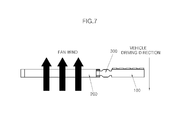
- FIG. 7 is a plan view of a structure of an intercooler cover integrated into a fan shroud according to an exemplary embodiment of the present inventive concept.
- FIG. 8 is a cross-sectional plan view of a structure of an intercooler cover integrated into a fan shroud according to an exemplary embodiment of the present inventive concept.
- FIG. 9 illustrates a state of a structure of an intercooler cover integrated into a fan shroud according to an exemplary embodiment of the present inventive concept when a vehicle is stopped with idling.
- FIG. 10 illustrates a state of a structure of an intercooler cover integrated into a fan shroud according to an exemplary embodiment of the present inventive concept when a vehicle travels.
- FIG. 11 is a flowchart of an operation method for a structure of an intercooler cover integrated into a fan shroud according to another exemplary embodiment of the present inventive concept.
- FIG. 5 is a rear perspective view of a structure of an intercooler cover integrated into a fan shroud according to an exemplary embodiment of the present inventive concept
- FIG. 6 is a front perspective view of a structure of an intercooler cover integrated into a fan shroud according to an exemplary embodiment of the present inventive concept.
- a structure of an intercooler cover integrated into a fan shroud may include an intercooler rear-side portion 100 which is mounted to a rear side of the intercooler; a cooling module rear-side portion 200 which is mounted to a rear side of a cooling module; and a ventilator 300 which communicates one side of the intercooler rear-side portion 100 with one side of the cooling module rear-side portion 200 .
- the structure of the intercooler cover integrated into the fan shroud according to the present disclosure includes at least one flap door 400 disposed at a surface which is vertical with respect to a vehicle driving direction in the intercooler rear-side portion 100 so as to block heat to be transferred from an engine compartment to the intercooler when a vehicle idles.
- the flap door 400 may be opened when the vehicle travels, and closed when the vehicle idles. That is, the flap door 400 may be opened by headwind during vehicle driving, and closed by its own weight during vehicle idling.
- the flap door 400 may be not limited thereto but may be controlled by an actuator and so on in order to be opened when the vehicle travels and to be closed when the vehicle idles.
- a material of the flap door 400 may be an insulator in order to prevent the heat in the engine compartment from being transferred to the intercooler when the vehicle stops so as to improve cooling efficiency of the intercooler. For this reason, the flap door 400 may be formed by a material having low heat conductivity.
- the structure of the intercooler cover integrated into the fan shroud according to the present disclosure may further include a hinge 500 , which is an elastic member, rotatably coupling the flap door 400 with the intercooler rear-side portion 100 . That is, the flap door 400 may be closed by not only the gravity according to the mass of the flap door 400 or the control of the additional actuator as described above but also the elastic restoring force of the hinge 500 when the vehicle stops.
- opening or closing the flap door 400 can be controlled by differently setting the mass of the flap door 400 or the elastic coefficient of the hinge 500 .
- the ventilator 300 may include a partition wall 310 which prevents air from flowing backward from the cooling module rear-side portion 200 to the intercooler rear-side portion 100 .
- the structure of the intercooler cover integrated into the fan shroud according to the present disclosure generates an air flow from the intercooler rear-side portion 100 to the cooling module rear-side portion 200 so as to increase the amount of air passing through the intercooler, thereby improving the cooling efficiency of the intercooler.
- the partition wall 310 may be formed at a side of the cooling module rear-side portion 200 .
- the partition wall 310 may include a first partition wall 311 which is formed from a front end toward a rear end of the ventilator 300 with respect to the vehicle driving direction and a second partition wall 312 which is slantingly formed from the rear end of the ventilator 300 into the ventilator 300 .
- the first partition wall 311 blocks the air flow guided by fan wind flowing into the ventilator 300
- the second partition wall 312 guides the air flow guided by fan wind to be easily discharged from the ventilator 300 to the cooling module rear-side portion 200 .
- the ventilator 300 has a central cross-sectional area that is wider than cross-sectional areas of both ends. That is, the ventilator 300 may have a diffuser shape having an increasing cross-sectional area, a pipe shape having a constant cross-sectional area, and a nozzle shape having a decreasing cross-section area, in which above listed cross-section areas are sequentially coupled along a direction from the intercooler rear-side portion 100 toward the cooling module rear-side portion 200 .
- the air flow guided by the fan wind (or a part of headwind passing through the intercooler) may generate noise by impacting on the partition wall 310 . Therefore, in order to reduce the above-mentioned noise, the central cross-sectional area of the ventilator 300 is enlarged so that air flow speed can be decreased temporarily.
- FIG. 7 is a plan view of a structure of an intercooler cover integrated into a fan shroud according to an exemplary embodiment of the present inventive concept
- FIG. 8 is a cross-sectional plan view of a structure of an intercooler cover integrated into a fan shroud according to an exemplary embodiment of the present inventive concept
- FIG. 9 illustrates a state of a structure of an intercooler cover integrated into a fan shroud according to an exemplary embodiment of the present inventive concept when a vehicle stops
- FIG. 10 illustrates a state of a structure of an intercooler cover integrated into a fan shroud according to an exemplary embodiment of the present inventive concept when a vehicle travels.
- the flap door 400 is closed as there is no headwind when a vehicle stops.
- fan wind is generated toward an opposite direction with respect to a vehicle driving direction as the fan of the cooling module is operated.
- the cooling module rear-side portion 200 In the cooling module rear-side portion 200 , an air flow speed increases but a pressure thereof decreases by the fan wind. Depending on the pressure difference, the air of the intercooler rear-side portion 100 flows to the cooling module rear-side portion 200 through the ventilator 300 . As a result, the cooling efficiency of the air-cooled intercooler increases when the vehicle stops with idling by generating an air flow passing through the intercooler even when the vehicle stops. Simultaneously, the flap door 400 , which is formed with an insulator, is closed so as to block heat of an engine compartment to be transferred to the intercooler, thereby increasing the cooling efficiency of the air-cooled intercooler when the vehicle stops traveling.
- the headwind is generated during vehicle driving such that the flap door 400 is opened.
- the fan of the cooling module is operated so as to generate the fan wind such that the headwind and the fan wind passing through the cooling module rear-side portion 200 are generated. Therefore, the air flow speed of the cooling module rear-side portion 200 generated by the headwind and the fan wind has a fast flow speed in comparison with the air flow of the intercooler rear-side portion 100 generated by only the headwind.
- the cooling module rear-side portion 200 becomes a state of low pressure in comparison with the intercooler rear-side portion 100 , and a part of air flow passing through the intercooler by the headwind forms an air flow guided from the intercooler rear-side portion 100 to the cooling module rear-side portion 200 .
- the amount of air flow passing through the intercooler is increased such that the high cooling efficiency is ensured even during vehicle driving in comparison with an air-cooled intercooler according to the prior art.
- the intercooler rear-side portion 110 may include a stopper 110 disposed at a part where the flap door 400 is mounted in order for the flap door 400 to be opened only toward a direction opposite to a vehicle driving direction.
- FIG. 11 is a flowchart of an operation method for a structure of an intercooler cover integrated into a fan shroud according to another exemplary embodiment of the present inventive concept.
- an operation method for a structure of an intercooler cover integrated into a fan shroud includes opening a flap door 400 by headwind when a vehicle travels (S 100 ); and closing the flap door 400 when a vehicle stops and idles (S 200 ).
- a skilled person in the relevant technology who has a typical knowledge in a technology field that the present disclosure belongs to, to execute the present disclosure easily but is not limited to the aforesaid exemplary embodiment and the attached drawings and hence this does not result in limiting the scope of right in this invention. Therefore, it will be apparent to a skilled person in the relevant technology that several transposition, transformation, and change is possible within a scope of not deviating from the technological thought in the present disclosure and it is obvious that a easily changeable part by a skilled person in the relevant technology is included within the scope of right in the present disclosure as well.
Landscapes
- Engineering & Computer Science (AREA)
- Chemical & Material Sciences (AREA)
- Combustion & Propulsion (AREA)
- Mechanical Engineering (AREA)
- General Engineering & Computer Science (AREA)
- Transportation (AREA)
- Physics & Mathematics (AREA)
- Thermal Sciences (AREA)
- Cooling, Air Intake And Gas Exhaust, And Fuel Tank Arrangements In Propulsion Units (AREA)
Abstract
A structure of an intercooler cover integrated into a fan shroud includes an intercooler rear-side portion mounted to a rear side of the intercooler. A cooling module rear-side portion is mounted to a rear side of a cooling module. A ventilator communicates with one side of the intercooler rear-side portion and one side of the cooling module rear-side portion.
Description
This application claims the benefit of priority to Korean Patent Application No. 10-2015-0048988 filed in the Korean Intellectual Property Office on Apr. 7, 2015, which is incorporated herein by reference in its entirety.
The present disclosure relates to a structure of an intercooler cover integrated into a fan shroud for a vehicle engine, and a method for operating the same, capable of improving efficiency of a conventional air-cooled intercooler.
Recently, a vehicle having a turbo engine has been rapidly increased for downsizing an engine and improving fuel consumption. Performance (such as engine output and fuel consumption) of the turbo engine is influenced by a cooling efficiency of an intercooler. Therefore, the cooling efficiency of the intercooler is a significant factor of vehicle performance. When the cooling efficiency of the intercooler is improved, the engine output and the fuel consumption may improve as a charging efficiency increases.
The intercooler may include a water-cooled charge air intercooler which cools the charge air by applying extra coolant and an air-cooled intercooler which cools the charge air by the headwind flowing thereinto through a radiator grille and an opening hole formed at a lower portion of a bumper cover. Among these, the water-cooled intercooler increases weight and cost because an additional device and the extra coolant are required.
Further, as shown in FIG. 4 , cooling efficiency of the intercooler significantly decreases because the cooling of the charge air using headwind is difficult when a vehicle idles, whereby engine output and fuel consumption are deteriorated.
The present disclosure has been made in an effort to provide a structure of an intercooler cover integrated into a fan shroud and a method for operating the same having advantages of guiding air flow in accordance with a pressure difference generated by fan wind of a cooling module.
A structure of an intercooler cover integrated into a fan shroud according to an exemplary embodiment of the present inventive concept may include an intercooler rear-side portion which covers a rear side of an intercooler. A cooling module rear-side portion covers a rear side of a cooling module. A ventilator communicates with one side of the intercooler rear-side portion and one side of the cooling module rear-side portion.
The structure may further include at least one flap door installed at another side of the intercooler rear-side portion which is vertical with respect to a vehicle driving direction to block heat to be transferred from an engine compartment to the intercooler when a vehicle stops and idles.
The structure of an intercooler cover integrated into a fan shroud may further include a hinge rotatably coupling the flap door with the intercooler rear-side portion.
The hinge may be a spring.
The flap door may be opened when the vehicle travels.
The flap door may be closed when the vehicle stops and idles.
The flap door may be formed of an insulator.
The ventilator may include a partition wall which prevents air from flowing backward from the cooling module rear-side portion to the intercooler rear-side portion.
The partition wall may be connected to the one side of the cooling module rear-side portion.
The partition wall may include a first partition wall which is connected to a front end toward a rear end of the ventilator with respect to the vehicle driving direction.
The partition wall may include a second partition wall which is slantingly installed at a rear end of the ventilator with respect to the vehicle driving direction into the ventilator.
A central cross-sectional area of the ventilator may be wider than cross-sectional areas of both ends thereof.
The ventilator may be have a diffuser shape having an increasing cross-sectional area, a pipe shape having a constant cross-sectional area, and a nozzle shape having a decreasing cross-sectional area. The cross-sectional areas of the ventilator are sequentially coupled along a direction from the intercooler rear-side portion toward the cooling module rear-side portion.
The intercooler rear-side portion may include a stopper formed at an opening of the flap door to open the flap door in one direction opposite to the vehicle driving direction.
An operation method for a structure of an intercooler cover integrated into a fan shroud according to another exemplary embodiment of the present inventive concept may include opening a flap door by using headwind when a vehicle travels, and closing the flap door when the vehicle stops and idles.
As described above, according to the present disclosure, the cooling efficiency of the intercooler increases by guiding the air flow in accordance with a pressure difference generated by fan wind when a vehicle idles such that vehicle performance such as vehicle output and fuel consumption can be improved.
Furthermore, the amount of air passing through the intercooler increases by guiding the air flow in accordance with the pressure difference generated by a fan wind even during vehicle driving such that the cooling efficiency of the intercooler increase, whereby vehicle performance such as vehicle output and fuel consumption can be improved.
Terms and words used in the present specification and claims are not to be construed as a general or dictionary meaning, but are to be construed as meaning and concepts meeting the technical ideas of the present disclosure based on a principle that the present inventors may appropriately define the present invention as the concepts of terms in order to describe their disclosures in best mode. Therefore, the configurations described in the exemplary embodiments and drawings of the present inventive concept are merely examples but do not represent all of the technical spirit of the present disclosure. Thus, the present disclosure should be construed as including all the changes, equivalents, and substitutions included in the spirit and scope of the present disclosure at the time of filing this application. Further, the detailed description of related well-known configurations and functions is not provided when it is determined as unnecessarily making the scope of the present disclosure unclear. An exemplary embodiment of the present inventive concept will hereinafter be described in detail with reference to the accompanying drawings.
The structure of the intercooler cover integrated into the fan shroud according to the present disclosure includes at least one flap door 400 disposed at a surface which is vertical with respect to a vehicle driving direction in the intercooler rear-side portion 100 so as to block heat to be transferred from an engine compartment to the intercooler when a vehicle idles.
The flap door 400 may be opened when the vehicle travels, and closed when the vehicle idles. That is, the flap door 400 may be opened by headwind during vehicle driving, and closed by its own weight during vehicle idling. The flap door 400 may be not limited thereto but may be controlled by an actuator and so on in order to be opened when the vehicle travels and to be closed when the vehicle idles.
A material of the flap door 400 may be an insulator in order to prevent the heat in the engine compartment from being transferred to the intercooler when the vehicle stops so as to improve cooling efficiency of the intercooler. For this reason, the flap door 400 may be formed by a material having low heat conductivity.
The structure of the intercooler cover integrated into the fan shroud according to the present disclosure may further include a hinge 500, which is an elastic member, rotatably coupling the flap door 400 with the intercooler rear-side portion 100. That is, the flap door 400 may be closed by not only the gravity according to the mass of the flap door 400 or the control of the additional actuator as described above but also the elastic restoring force of the hinge 500 when the vehicle stops. Here, opening or closing the flap door 400 can be controlled by differently setting the mass of the flap door 400 or the elastic coefficient of the hinge 500.
The ventilator 300 may include a partition wall 310 which prevents air from flowing backward from the cooling module rear-side portion 200 to the intercooler rear-side portion 100. The structure of the intercooler cover integrated into the fan shroud according to the present disclosure generates an air flow from the intercooler rear-side portion 100 to the cooling module rear-side portion 200 so as to increase the amount of air passing through the intercooler, thereby improving the cooling efficiency of the intercooler.
The partition wall 310 may be formed at a side of the cooling module rear-side portion 200. The partition wall 310 may include a first partition wall 311 which is formed from a front end toward a rear end of the ventilator 300 with respect to the vehicle driving direction and a second partition wall 312 which is slantingly formed from the rear end of the ventilator 300 into the ventilator 300. In other words, the first partition wall 311 blocks the air flow guided by fan wind flowing into the ventilator 300, and the second partition wall 312 guides the air flow guided by fan wind to be easily discharged from the ventilator 300 to the cooling module rear-side portion 200.
The ventilator 300 has a central cross-sectional area that is wider than cross-sectional areas of both ends. That is, the ventilator 300 may have a diffuser shape having an increasing cross-sectional area, a pipe shape having a constant cross-sectional area, and a nozzle shape having a decreasing cross-section area, in which above listed cross-section areas are sequentially coupled along a direction from the intercooler rear-side portion 100 toward the cooling module rear-side portion 200. The air flow guided by the fan wind (or a part of headwind passing through the intercooler) may generate noise by impacting on the partition wall 310. Therefore, in order to reduce the above-mentioned noise, the central cross-sectional area of the ventilator 300 is enlarged so that air flow speed can be decreased temporarily.
Referring to FIGS. 7-10 , according to the structure of an intercooler cover integrated into a fan shroud according to an exemplary embodiment of the present inventive concept, the flap door 400 is closed as there is no headwind when a vehicle stops.
On the other hand, fan wind is generated toward an opposite direction with respect to a vehicle driving direction as the fan of the cooling module is operated.
In the cooling module rear-side portion 200, an air flow speed increases but a pressure thereof decreases by the fan wind. Depending on the pressure difference, the air of the intercooler rear-side portion 100 flows to the cooling module rear-side portion 200 through the ventilator 300. As a result, the cooling efficiency of the air-cooled intercooler increases when the vehicle stops with idling by generating an air flow passing through the intercooler even when the vehicle stops. Simultaneously, the flap door 400, which is formed with an insulator, is closed so as to block heat of an engine compartment to be transferred to the intercooler, thereby increasing the cooling efficiency of the air-cooled intercooler when the vehicle stops traveling.
The headwind is generated during vehicle driving such that the flap door 400 is opened. Simultaneously, the fan of the cooling module is operated so as to generate the fan wind such that the headwind and the fan wind passing through the cooling module rear-side portion 200 are generated. Therefore, the air flow speed of the cooling module rear-side portion 200 generated by the headwind and the fan wind has a fast flow speed in comparison with the air flow of the intercooler rear-side portion 100 generated by only the headwind. Thus, the cooling module rear-side portion 200 becomes a state of low pressure in comparison with the intercooler rear-side portion 100, and a part of air flow passing through the intercooler by the headwind forms an air flow guided from the intercooler rear-side portion 100 to the cooling module rear-side portion 200. Thus, the amount of air flow passing through the intercooler is increased such that the high cooling efficiency is ensured even during vehicle driving in comparison with an air-cooled intercooler according to the prior art.
The intercooler rear-side portion 110 may include a stopper 110 disposed at a part where the flap door 400 is mounted in order for the flap door 400 to be opened only toward a direction opposite to a vehicle driving direction.
The exemplary embodiments as discussed previously are merely examples which may enable a person (hereinafter referred to as ‘a skilled person in the relevant technology’), who has a typical knowledge in a technology field that the present disclosure belongs to, to execute the present disclosure easily but is not limited to the aforesaid exemplary embodiment and the attached drawings and hence this does not result in limiting the scope of right in this invention. Therefore, it will be apparent to a skilled person in the relevant technology that several transposition, transformation, and change is possible within a scope of not deviating from the technological thought in the present disclosure and it is obvious that a easily changeable part by a skilled person in the relevant technology is included within the scope of right in the present disclosure as well.
Claims (17)
1. A structure of a vehicle intercooler cover integrated into a fan shroud, the structure comprising:
an intercooler rear-side portion which covers a rear side of an intercooler;
a cooling module rear-side portion which covers a rear side of a cooling module; and
a ventilator which allows communication between one side of the intercooler rear-side portion and one side of the cooling module rear-side portion,
wherein the ventilator comprises a partition wall which prevents air from flowing backward from the cooling module rear-side portion to the intercooler rear-side portion.
2. The structure of claim 1 , further comprising:
at least one flap door which is installed at another side of the intercooler rear-side portion, the other side being vertical to a vehicle driving direction to block heat to be transferred from an engine compartment to the intercooler when a vehicle stops and idles.
3. The structure of claim 2 , further comprising:
a hinge rotatably coupling the flap door with the intercooler rear-side portion.
4. The structure of claim 3 , wherein the hinge is a spring.
5. The structure of claim 2 , wherein the flap door is opened when the vehicle travels.
6. The structure of claim 2 , wherein the flap door is closed when the vehicle stops with idling.
7. The structure of claim 2 , wherein the flap door is formed of an insulator.
8. The structure of claim 2 , wherein the intercooler rear-side portion comprises a stopper formed at an opening of the flap door to open the flap door in one direction opposite to the vehicle driving direction.
9. The structure of claim 1 , wherein the partition wall is installed at the one side of the cooling module rear-side portion.
10. The structure of claim 1 , wherein the partition wall comprises a first partition wall which is connected to a front end toward a rear end of the ventilator with respect to a vehicle driving direction.
11. The structure of claim 1 , wherein the partition wall comprises a second partition wall which is slantingly connected to a rear end of the ventilator with respect to a vehicle driving direction into the ventilator.
12. The structure of claim 1 , wherein a central cross-sectional area of the ventilator is wider than cross-sectional areas of both ends of the ventilator.
13. The structure of claim 12 , wherein the ventilator has a diffuser shape having an increasing cross-sectional area, a pipe shape having a uniform cross-sectional area, and a nozzle shape having a decreasing cross-sectional area,
wherein the cross-sectional areas of the ventilator are sequentially coupled from the intercooler rear-side portion toward the cooling module rear-side portion.
14. A method for operating a structure of a vehicle intercooler cover integrated into a fan shroud, the method comprising:
opening a flap door by headwind when a vehicle travels; and
closing the flap door when the vehicle stops and idles
wherein the structure includes an intercooler rear-side portion, a cooling module rear-side portion, and a ventilator, and
wherein the ventilator allows communication between the intercooler rear-side portion and the cooling module rear-side portion and has a partition wall which prevents air from flowing backward from the cooling module rear-side portion to the intercooler rear-side portion.
15. The method of claim 14 , further comprising prior to the step of opening:
determining whether the vehicle travels.
16. The method of claim 15 , comprising:
closing the flap door when the vehicle does not travel.
17. The method of claim 14 , further comprising:
determining whether a vehicle engine is off.
Applications Claiming Priority (2)
| Application Number | Priority Date | Filing Date | Title |
|---|---|---|---|
| KR1020150048988A KR101646456B1 (en) | 2015-04-07 | 2015-04-07 | A structure of encapsulation integrated into fan-shroud and a method of operating thereof |
| KR10-2015-0048988 | 2015-04-07 |
Publications (2)
| Publication Number | Publication Date |
|---|---|
| US20160298524A1 US20160298524A1 (en) | 2016-10-13 |
| US9951675B2 true US9951675B2 (en) | 2018-04-24 |
Family
ID=54478576
Family Applications (1)
| Application Number | Title | Priority Date | Filing Date |
|---|---|---|---|
| US14/926,906 Active 2036-07-18 US9951675B2 (en) | 2015-04-07 | 2015-10-29 | Structure of intercooler cover integrated into fan shroud for turbocharged engine and method for operating the same |
Country Status (4)
| Country | Link |
|---|---|
| US (1) | US9951675B2 (en) |
| EP (1) | EP3078528B1 (en) |
| KR (1) | KR101646456B1 (en) |
| CN (1) | CN106042901B (en) |
Cited By (2)
| Publication number | Priority date | Publication date | Assignee | Title |
|---|---|---|---|---|
| US11065951B2 (en) * | 2016-05-11 | 2021-07-20 | Ningbo Geely Automobile Research & Development Co. | Charge air shutter |
| TWI759930B (en) * | 2020-10-29 | 2022-04-01 | 三陽工業股份有限公司 | Water tank structure for motorcycle |
Families Citing this family (3)
| Publication number | Priority date | Publication date | Assignee | Title |
|---|---|---|---|---|
| CN107120170A (en) * | 2017-06-09 | 2017-09-01 | 同济大学 | A kind of fan guard and its control method for cooling module of engine |
| DE102018214283B3 (en) * | 2018-08-23 | 2019-12-19 | Brose Fahrzeugteile GmbH & Co. Kommanditgesellschaft, Würzburg | Frame device and fan module with such a frame device |
| CN111267605B (en) * | 2020-03-31 | 2023-03-28 | 重庆长安汽车股份有限公司 | Engine compartment drainage structure |
Citations (15)
| Publication number | Priority date | Publication date | Assignee | Title |
|---|---|---|---|---|
| KR19980049936U (en) | 1996-12-30 | 1998-10-07 | 김영귀 | Assembly of Radiator Grille with Exposure Block |
| US20040104007A1 (en) | 2002-11-06 | 2004-06-03 | Transpro, Inc. | Heat exchanger package |
| US20040163864A1 (en) | 2002-08-22 | 2004-08-26 | Norihisa Sasano | Vehicle front end structure |
| WO2005119024A1 (en) | 2004-05-26 | 2005-12-15 | Behr Gmbh & Co. Kg | Cooling system |
| KR100792905B1 (en) | 2006-12-14 | 2008-01-09 | 현대자동차주식회사 | Cooling module mounting structure in vehicle |
| KR20080010526A (en) | 2006-07-27 | 2008-01-31 | 한라공조주식회사 | Intercooler cooling structure |
| KR20080043971A (en) | 2006-11-15 | 2008-05-20 | 현대자동차주식회사 | Inter cooler module structure |
| WO2008111906A1 (en) | 2007-03-15 | 2008-09-18 | Scania Cv Ab | Cooling arrangement in a vehicle |
| KR20100030332A (en) | 2008-09-10 | 2010-03-18 | 현대모비스 주식회사 | Cooling module integrated with intercooler for vehicle |
| JP2011025812A (en) | 2009-07-24 | 2011-02-10 | Honda Motor Co Ltd | Vehicle, and method for regulating temperature of power storage device |
| KR20110061216A (en) | 2009-12-01 | 2011-06-09 | 현대자동차주식회사 | Structure for condenser-intercooler intergrated cooling module |
| JP2011126328A (en) | 2009-12-15 | 2011-06-30 | Mitsubishi Fuso Truck & Bus Corp | Cooling device for engine |
| JP2011127449A (en) | 2009-12-15 | 2011-06-30 | Mitsubishi Fuso Truck & Bus Corp | Cooling device for engine |
| KR20120063116A (en) | 2010-12-07 | 2012-06-15 | 현대자동차주식회사 | Intercooler guide duct |
| KR20130028424A (en) | 2011-09-09 | 2013-03-19 | 한라공조주식회사 | Carrier for motor vehicle |
Family Cites Families (4)
| Publication number | Priority date | Publication date | Assignee | Title |
|---|---|---|---|---|
| DE102004060960A1 (en) * | 2004-12-17 | 2006-06-29 | Still Gmbh | Industrial truck e.g. counterbalance fork-lift truck, has common ventilator device with adjustable blower for supplying air to fuel cell unit and cooling device, where blower is arranged in airflow upstream of cell unit and cooling device |
| CN201250698Y (en) * | 2008-09-10 | 2009-06-03 | 王宗荣 | Inlet cooling device for an automotive engine |
| JP5033226B2 (en) * | 2010-08-02 | 2012-09-26 | 株式会社小松製作所 | Work vehicle |
| FR2975765B1 (en) * | 2011-05-26 | 2016-01-29 | Valeo Systemes Thermiques | THERMAL EXCHANGER, IN PARTICULAR FOR MOTOR VEHICLE, AND CORRESPONDING AIR INTAKE DEVICE |
-
2015
- 2015-04-07 KR KR1020150048988A patent/KR101646456B1/en active IP Right Grant
- 2015-10-29 US US14/926,906 patent/US9951675B2/en active Active
- 2015-11-02 EP EP15192516.1A patent/EP3078528B1/en not_active Not-in-force
- 2015-11-13 CN CN201510781735.7A patent/CN106042901B/en not_active Expired - Fee Related
Patent Citations (16)
| Publication number | Priority date | Publication date | Assignee | Title |
|---|---|---|---|---|
| KR19980049936U (en) | 1996-12-30 | 1998-10-07 | 김영귀 | Assembly of Radiator Grille with Exposure Block |
| US20040163864A1 (en) | 2002-08-22 | 2004-08-26 | Norihisa Sasano | Vehicle front end structure |
| US20040104007A1 (en) | 2002-11-06 | 2004-06-03 | Transpro, Inc. | Heat exchanger package |
| WO2005119024A1 (en) | 2004-05-26 | 2005-12-15 | Behr Gmbh & Co. Kg | Cooling system |
| US20080017138A1 (en) * | 2004-05-26 | 2008-01-24 | Behr Gmbh & Co. Kg | Cooling System |
| KR20080010526A (en) | 2006-07-27 | 2008-01-31 | 한라공조주식회사 | Intercooler cooling structure |
| KR20080043971A (en) | 2006-11-15 | 2008-05-20 | 현대자동차주식회사 | Inter cooler module structure |
| KR100792905B1 (en) | 2006-12-14 | 2008-01-09 | 현대자동차주식회사 | Cooling module mounting structure in vehicle |
| WO2008111906A1 (en) | 2007-03-15 | 2008-09-18 | Scania Cv Ab | Cooling arrangement in a vehicle |
| KR20100030332A (en) | 2008-09-10 | 2010-03-18 | 현대모비스 주식회사 | Cooling module integrated with intercooler for vehicle |
| JP2011025812A (en) | 2009-07-24 | 2011-02-10 | Honda Motor Co Ltd | Vehicle, and method for regulating temperature of power storage device |
| KR20110061216A (en) | 2009-12-01 | 2011-06-09 | 현대자동차주식회사 | Structure for condenser-intercooler intergrated cooling module |
| JP2011126328A (en) | 2009-12-15 | 2011-06-30 | Mitsubishi Fuso Truck & Bus Corp | Cooling device for engine |
| JP2011127449A (en) | 2009-12-15 | 2011-06-30 | Mitsubishi Fuso Truck & Bus Corp | Cooling device for engine |
| KR20120063116A (en) | 2010-12-07 | 2012-06-15 | 현대자동차주식회사 | Intercooler guide duct |
| KR20130028424A (en) | 2011-09-09 | 2013-03-19 | 한라공조주식회사 | Carrier for motor vehicle |
Non-Patent Citations (1)
| Title |
|---|
| Search Report dated Jul. 11, 2016, issued in European Patent Application No. 15192516.1. |
Cited By (2)
| Publication number | Priority date | Publication date | Assignee | Title |
|---|---|---|---|---|
| US11065951B2 (en) * | 2016-05-11 | 2021-07-20 | Ningbo Geely Automobile Research & Development Co. | Charge air shutter |
| TWI759930B (en) * | 2020-10-29 | 2022-04-01 | 三陽工業股份有限公司 | Water tank structure for motorcycle |
Also Published As
| Publication number | Publication date |
|---|---|
| KR101646456B1 (en) | 2016-08-05 |
| CN106042901A (en) | 2016-10-26 |
| EP3078528A1 (en) | 2016-10-12 |
| EP3078528B1 (en) | 2017-07-19 |
| US20160298524A1 (en) | 2016-10-13 |
| CN106042901B (en) | 2020-07-14 |
Similar Documents
| Publication | Publication Date | Title |
|---|---|---|
| US9951675B2 (en) | Structure of intercooler cover integrated into fan shroud for turbocharged engine and method for operating the same | |
| US8752660B2 (en) | Cooling structure for vehicles | |
| KR101637305B1 (en) | Airflow guiding system for vehicle | |
| US20070119395A1 (en) | Cooling device of vehicle | |
| WO2015129348A1 (en) | Cooling module | |
| JP2007099194A (en) | Airflow guiding structure of vehicular cooling system | |
| US20150118949A1 (en) | Airflow guiding system for vehicle | |
| JP6416651B2 (en) | Shutter opening / closing control device for vehicle | |
| JP2010069898A (en) | Vehicular cooling system | |
| US9738153B2 (en) | Intercooler air-guide of dual duct type for improving crash performance | |
| KR20210056795A (en) | Wheel house structure | |
| KR101628451B1 (en) | Encapsulation device for inter cooler of vehicle | |
| KR101805715B1 (en) | Airflap apparatus for an automobile | |
| KR101238859B1 (en) | Under cover for vehicle and vehicle including the same | |
| JP3168796B2 (en) | Front structure of vehicle with reduced air resistance | |
| JP2007170241A (en) | Engine cover structure | |
| KR20120063116A (en) | Intercooler guide duct | |
| KR100514534B1 (en) | Intercooler system in automobile | |
| JP2021095018A (en) | Intercooler cooling structure | |
| KR20160120947A (en) | Active air flap | |
| KR102518553B1 (en) | Aerodynamic apparatus for vehicle | |
| US20200340392A1 (en) | Cooling air feeding apparatus for a motor vehicle | |
| KR101238860B1 (en) | Air discharge structure for engine room of vehicle and vehicle including the same | |
| JP2021070329A (en) | Vehicle front structure | |
| JP2005029028A (en) | Outside air intake structure for vehicle |
Legal Events
| Date | Code | Title | Description |
|---|---|---|---|
| AS | Assignment |
Owner name: HYUNDAI MOTOR COMPANY, KOREA, REPUBLIC OF Free format text: ASSIGNMENT OF ASSIGNORS INTEREST;ASSIGNORS:PARK, DANG-HEE;PARK, YONG-BEOM;KIM, BONG-SOO;REEL/FRAME:036916/0281 Effective date: 20150917 |
|
| STCF | Information on status: patent grant |
Free format text: PATENTED CASE |
|
| MAFP | Maintenance fee payment |
Free format text: PAYMENT OF MAINTENANCE FEE, 4TH YEAR, LARGE ENTITY (ORIGINAL EVENT CODE: M1551); ENTITY STATUS OF PATENT OWNER: LARGE ENTITY Year of fee payment: 4 |