US9931132B2 - Dissecting cannula and methods of use thereof - Google Patents
Dissecting cannula and methods of use thereof Download PDFInfo
- Publication number
- US9931132B2 US9931132B2 US14/668,479 US201514668479A US9931132B2 US 9931132 B2 US9931132 B2 US 9931132B2 US 201514668479 A US201514668479 A US 201514668479A US 9931132 B2 US9931132 B2 US 9931132B2
- Authority
- US
- United States
- Prior art keywords
- cannula
- dilation
- fluid
- tissue
- wedge
- Prior art date
- Legal status (The legal status is an assumption and is not a legal conclusion. Google has not performed a legal analysis and makes no representation as to the accuracy of the status listed.)
- Active, expires
Links
- 238000000034 method Methods 0.000 title abstract description 34
- 238000002224 dissection Methods 0.000 claims abstract description 78
- 239000012530 fluid Substances 0.000 claims description 91
- 230000010339 dilation Effects 0.000 claims description 51
- 239000000463 material Substances 0.000 claims description 19
- 230000007704 transition Effects 0.000 claims description 8
- 238000004891 communication Methods 0.000 claims description 6
- 230000000916 dilatatory effect Effects 0.000 claims description 5
- 239000000835 fiber Substances 0.000 claims description 5
- 230000008878 coupling Effects 0.000 claims description 3
- 238000010168 coupling process Methods 0.000 claims description 3
- 238000005859 coupling reaction Methods 0.000 claims description 3
- 230000000007 visual effect Effects 0.000 claims 5
- 210000001519 tissue Anatomy 0.000 description 81
- 230000015271 coagulation Effects 0.000 description 38
- 238000005345 coagulation Methods 0.000 description 38
- 230000001746 atrial effect Effects 0.000 description 18
- 230000003902 lesion Effects 0.000 description 17
- 239000000523 sample Substances 0.000 description 13
- 238000012800 visualization Methods 0.000 description 12
- 210000000115 thoracic cavity Anatomy 0.000 description 10
- 210000005245 right atrium Anatomy 0.000 description 8
- 210000004872 soft tissue Anatomy 0.000 description 6
- 238000002679 ablation Methods 0.000 description 5
- 210000000056 organ Anatomy 0.000 description 5
- 238000001356 surgical procedure Methods 0.000 description 5
- 206010003658 Atrial Fibrillation Diseases 0.000 description 4
- 238000013459 approach Methods 0.000 description 4
- 230000002262 irrigation Effects 0.000 description 4
- 238000003973 irrigation Methods 0.000 description 4
- 210000005246 left atrium Anatomy 0.000 description 4
- 210000003492 pulmonary vein Anatomy 0.000 description 4
- 238000012384 transportation and delivery Methods 0.000 description 4
- 210000001782 transverse sinus Anatomy 0.000 description 4
- 238000004140 cleaning Methods 0.000 description 3
- 210000001015 abdomen Anatomy 0.000 description 2
- 238000005299 abrasion Methods 0.000 description 2
- 238000007792 addition Methods 0.000 description 2
- 230000008901 benefit Effects 0.000 description 2
- 210000000038 chest Anatomy 0.000 description 2
- 239000004744 fabric Substances 0.000 description 2
- 238000010438 heat treatment Methods 0.000 description 2
- 238000003780 insertion Methods 0.000 description 2
- 230000037431 insertion Effects 0.000 description 2
- 239000010410 layer Substances 0.000 description 2
- 238000002324 minimally invasive surgery Methods 0.000 description 2
- 238000012986 modification Methods 0.000 description 2
- 230000004048 modification Effects 0.000 description 2
- 210000003516 pericardium Anatomy 0.000 description 2
- 238000012546 transfer Methods 0.000 description 2
- 102000008186 Collagen Human genes 0.000 description 1
- 108010035532 Collagen Proteins 0.000 description 1
- 229920000742 Cotton Polymers 0.000 description 1
- 206010028980 Neoplasm Diseases 0.000 description 1
- 241000270295 Serpentes Species 0.000 description 1
- 208000027418 Wounds and injury Diseases 0.000 description 1
- 230000002745 absorbent Effects 0.000 description 1
- 239000002250 absorbent Substances 0.000 description 1
- 206010003119 arrhythmia Diseases 0.000 description 1
- 230000006793 arrhythmia Effects 0.000 description 1
- 230000009286 beneficial effect Effects 0.000 description 1
- 239000008280 blood Substances 0.000 description 1
- 210000004369 blood Anatomy 0.000 description 1
- 210000001124 body fluid Anatomy 0.000 description 1
- 230000036760 body temperature Effects 0.000 description 1
- 201000011510 cancer Diseases 0.000 description 1
- 206010061592 cardiac fibrillation Diseases 0.000 description 1
- 230000008859 change Effects 0.000 description 1
- 238000001311 chemical methods and process Methods 0.000 description 1
- 239000011248 coating agent Substances 0.000 description 1
- 238000000576 coating method Methods 0.000 description 1
- 229920001436 collagen Polymers 0.000 description 1
- 238000009833 condensation Methods 0.000 description 1
- 230000005494 condensation Effects 0.000 description 1
- 230000008602 contraction Effects 0.000 description 1
- 230000006378 damage Effects 0.000 description 1
- 230000002600 fibrillogenic effect Effects 0.000 description 1
- 239000008187 granular material Substances 0.000 description 1
- 210000002837 heart atrium Anatomy 0.000 description 1
- 238000002347 injection Methods 0.000 description 1
- 239000007924 injection Substances 0.000 description 1
- 208000014674 injury Diseases 0.000 description 1
- 230000001788 irregular Effects 0.000 description 1
- 230000002427 irreversible effect Effects 0.000 description 1
- 210000004072 lung Anatomy 0.000 description 1
- 238000010297 mechanical methods and process Methods 0.000 description 1
- 210000004115 mitral valve Anatomy 0.000 description 1
- 208000005907 mitral valve insufficiency Diseases 0.000 description 1
- 238000002355 open surgical procedure Methods 0.000 description 1
- 230000010412 perfusion Effects 0.000 description 1
- 239000013047 polymeric layer Substances 0.000 description 1
- 229920001296 polysiloxane Polymers 0.000 description 1
- 230000008569 process Effects 0.000 description 1
- 238000007493 shaping process Methods 0.000 description 1
- 239000000758 substrate Substances 0.000 description 1
- 206010047302 ventricular tachycardia Diseases 0.000 description 1
Images


Classifications
-
- A—HUMAN NECESSITIES
- A61—MEDICAL OR VETERINARY SCIENCE; HYGIENE
- A61B—DIAGNOSIS; SURGERY; IDENTIFICATION
- A61B17/00—Surgical instruments, devices or methods, e.g. tourniquets
- A61B17/32—Surgical cutting instruments
- A61B17/320016—Endoscopic cutting instruments, e.g. arthroscopes, resectoscopes
-
- A—HUMAN NECESSITIES
- A61—MEDICAL OR VETERINARY SCIENCE; HYGIENE
- A61B—DIAGNOSIS; SURGERY; IDENTIFICATION
- A61B17/00—Surgical instruments, devices or methods, e.g. tourniquets
- A61B17/32—Surgical cutting instruments
- A61B17/3205—Excision instruments
- A61B17/3207—Atherectomy devices working by cutting or abrading; Similar devices specially adapted for non-vascular obstructions
-
- A—HUMAN NECESSITIES
- A61—MEDICAL OR VETERINARY SCIENCE; HYGIENE
- A61B—DIAGNOSIS; SURGERY; IDENTIFICATION
- A61B18/00—Surgical instruments, devices or methods for transferring non-mechanical forms of energy to or from the body
- A61B18/04—Surgical instruments, devices or methods for transferring non-mechanical forms of energy to or from the body by heating
- A61B18/12—Surgical instruments, devices or methods for transferring non-mechanical forms of energy to or from the body by heating by passing a current through the tissue to be heated, e.g. high-frequency current
- A61B18/14—Probes or electrodes therefor
- A61B18/1492—Probes or electrodes therefor having a flexible, catheter-like structure, e.g. for heart ablation
-
- A—HUMAN NECESSITIES
- A61—MEDICAL OR VETERINARY SCIENCE; HYGIENE
- A61B—DIAGNOSIS; SURGERY; IDENTIFICATION
- A61B90/00—Instruments, implements or accessories specially adapted for surgery or diagnosis and not covered by any of the groups A61B1/00 - A61B50/00, e.g. for luxation treatment or for protecting wound edges
- A61B90/36—Image-producing devices or illumination devices not otherwise provided for
- A61B90/361—Image-producing devices, e.g. surgical cameras
-
- A—HUMAN NECESSITIES
- A61—MEDICAL OR VETERINARY SCIENCE; HYGIENE
- A61B—DIAGNOSIS; SURGERY; IDENTIFICATION
- A61B17/00—Surgical instruments, devices or methods, e.g. tourniquets
- A61B17/32—Surgical cutting instruments
- A61B17/320068—Surgical cutting instruments using mechanical vibrations, e.g. ultrasonic
-
- A—HUMAN NECESSITIES
- A61—MEDICAL OR VETERINARY SCIENCE; HYGIENE
- A61B—DIAGNOSIS; SURGERY; IDENTIFICATION
- A61B18/00—Surgical instruments, devices or methods for transferring non-mechanical forms of energy to or from the body
- A61B18/04—Surgical instruments, devices or methods for transferring non-mechanical forms of energy to or from the body by heating
- A61B18/08—Surgical instruments, devices or methods for transferring non-mechanical forms of energy to or from the body by heating by means of electrically-heated probes
- A61B18/082—Probes or electrodes therefor
-
- A—HUMAN NECESSITIES
- A61—MEDICAL OR VETERINARY SCIENCE; HYGIENE
- A61B—DIAGNOSIS; SURGERY; IDENTIFICATION
- A61B17/00—Surgical instruments, devices or methods, e.g. tourniquets
- A61B17/00234—Surgical instruments, devices or methods, e.g. tourniquets for minimally invasive surgery
- A61B2017/00238—Type of minimally invasive operation
- A61B2017/00243—Type of minimally invasive operation cardiac
-
- A—HUMAN NECESSITIES
- A61—MEDICAL OR VETERINARY SCIENCE; HYGIENE
- A61B—DIAGNOSIS; SURGERY; IDENTIFICATION
- A61B17/00—Surgical instruments, devices or methods, e.g. tourniquets
- A61B17/22—Implements for squeezing-off ulcers or the like on the inside of inner organs of the body; Implements for scraping-out cavities of body organs, e.g. bones; Calculus removers; Calculus smashing apparatus; Apparatus for removing obstructions in blood vessels, not otherwise provided for
- A61B2017/22038—Implements for squeezing-off ulcers or the like on the inside of inner organs of the body; Implements for scraping-out cavities of body organs, e.g. bones; Calculus removers; Calculus smashing apparatus; Apparatus for removing obstructions in blood vessels, not otherwise provided for with a guide wire
-
- A—HUMAN NECESSITIES
- A61—MEDICAL OR VETERINARY SCIENCE; HYGIENE
- A61B—DIAGNOSIS; SURGERY; IDENTIFICATION
- A61B17/00—Surgical instruments, devices or methods, e.g. tourniquets
- A61B17/22—Implements for squeezing-off ulcers or the like on the inside of inner organs of the body; Implements for scraping-out cavities of body organs, e.g. bones; Calculus removers; Calculus smashing apparatus; Apparatus for removing obstructions in blood vessels, not otherwise provided for
- A61B2017/22079—Implements for squeezing-off ulcers or the like on the inside of inner organs of the body; Implements for scraping-out cavities of body organs, e.g. bones; Calculus removers; Calculus smashing apparatus; Apparatus for removing obstructions in blood vessels, not otherwise provided for with suction of debris
-
- A—HUMAN NECESSITIES
- A61—MEDICAL OR VETERINARY SCIENCE; HYGIENE
- A61B—DIAGNOSIS; SURGERY; IDENTIFICATION
- A61B17/00—Surgical instruments, devices or methods, e.g. tourniquets
- A61B17/32—Surgical cutting instruments
- A61B2017/320004—Surgical cutting instruments abrasive
-
- A—HUMAN NECESSITIES
- A61—MEDICAL OR VETERINARY SCIENCE; HYGIENE
- A61B—DIAGNOSIS; SURGERY; IDENTIFICATION
- A61B17/00—Surgical instruments, devices or methods, e.g. tourniquets
- A61B17/32—Surgical cutting instruments
- A61B2017/320004—Surgical cutting instruments abrasive
- A61B2017/320008—Scrapers
-
- A—HUMAN NECESSITIES
- A61—MEDICAL OR VETERINARY SCIENCE; HYGIENE
- A61B—DIAGNOSIS; SURGERY; IDENTIFICATION
- A61B17/00—Surgical instruments, devices or methods, e.g. tourniquets
- A61B17/32—Surgical cutting instruments
- A61B2017/320004—Surgical cutting instruments abrasive
- A61B2017/320012—Brushes
-
- A—HUMAN NECESSITIES
- A61—MEDICAL OR VETERINARY SCIENCE; HYGIENE
- A61B—DIAGNOSIS; SURGERY; IDENTIFICATION
- A61B17/00—Surgical instruments, devices or methods, e.g. tourniquets
- A61B17/32—Surgical cutting instruments
- A61B2017/320044—Blunt dissectors
-
- A—HUMAN NECESSITIES
- A61—MEDICAL OR VETERINARY SCIENCE; HYGIENE
- A61B—DIAGNOSIS; SURGERY; IDENTIFICATION
- A61B17/00—Surgical instruments, devices or methods, e.g. tourniquets
- A61B17/32—Surgical cutting instruments
- A61B2017/320044—Blunt dissectors
- A61B2017/320048—Balloon dissectors
-
- A—HUMAN NECESSITIES
- A61—MEDICAL OR VETERINARY SCIENCE; HYGIENE
- A61B—DIAGNOSIS; SURGERY; IDENTIFICATION
- A61B17/00—Surgical instruments, devices or methods, e.g. tourniquets
- A61B17/32—Surgical cutting instruments
- A61B17/320068—Surgical cutting instruments using mechanical vibrations, e.g. ultrasonic
- A61B2017/320069—Surgical cutting instruments using mechanical vibrations, e.g. ultrasonic for ablating tissue
-
- A—HUMAN NECESSITIES
- A61—MEDICAL OR VETERINARY SCIENCE; HYGIENE
- A61B—DIAGNOSIS; SURGERY; IDENTIFICATION
- A61B17/00—Surgical instruments, devices or methods, e.g. tourniquets
- A61B17/32—Surgical cutting instruments
- A61B17/320068—Surgical cutting instruments using mechanical vibrations, e.g. ultrasonic
- A61B2017/32007—Surgical cutting instruments using mechanical vibrations, e.g. ultrasonic with suction or vacuum means
-
- A—HUMAN NECESSITIES
- A61—MEDICAL OR VETERINARY SCIENCE; HYGIENE
- A61B—DIAGNOSIS; SURGERY; IDENTIFICATION
- A61B17/00—Surgical instruments, devices or methods, e.g. tourniquets
- A61B17/34—Trocars; Puncturing needles
- A61B17/3417—Details of tips or shafts, e.g. grooves, expandable, bendable; Multiple coaxial sliding cannulas, e.g. for dilating
- A61B17/3421—Cannulas
- A61B2017/3445—Cannulas used as instrument channel for multiple instruments
-
- A—HUMAN NECESSITIES
- A61—MEDICAL OR VETERINARY SCIENCE; HYGIENE
- A61B—DIAGNOSIS; SURGERY; IDENTIFICATION
- A61B18/00—Surgical instruments, devices or methods for transferring non-mechanical forms of energy to or from the body
- A61B2018/00315—Surgical instruments, devices or methods for transferring non-mechanical forms of energy to or from the body for treatment of particular body parts
- A61B2018/00345—Vascular system
- A61B2018/00351—Heart
- A61B2018/00363—Epicardium
-
- A—HUMAN NECESSITIES
- A61—MEDICAL OR VETERINARY SCIENCE; HYGIENE
- A61B—DIAGNOSIS; SURGERY; IDENTIFICATION
- A61B18/00—Surgical instruments, devices or methods for transferring non-mechanical forms of energy to or from the body
- A61B2018/00571—Surgical instruments, devices or methods for transferring non-mechanical forms of energy to or from the body for achieving a particular surgical effect
- A61B2018/00577—Ablation
-
- A—HUMAN NECESSITIES
- A61—MEDICAL OR VETERINARY SCIENCE; HYGIENE
- A61B—DIAGNOSIS; SURGERY; IDENTIFICATION
- A61B18/00—Surgical instruments, devices or methods for transferring non-mechanical forms of energy to or from the body
- A61B2018/00571—Surgical instruments, devices or methods for transferring non-mechanical forms of energy to or from the body for achieving a particular surgical effect
- A61B2018/00589—Coagulation
-
- A—HUMAN NECESSITIES
- A61—MEDICAL OR VETERINARY SCIENCE; HYGIENE
- A61B—DIAGNOSIS; SURGERY; IDENTIFICATION
- A61B90/00—Instruments, implements or accessories specially adapted for surgery or diagnosis and not covered by any of the groups A61B1/00 - A61B50/00, e.g. for luxation treatment or for protecting wound edges
- A61B90/36—Image-producing devices or illumination devices not otherwise provided for
- A61B90/361—Image-producing devices, e.g. surgical cameras
- A61B2090/3614—Image-producing devices, e.g. surgical cameras using optical fibre
-
- A—HUMAN NECESSITIES
- A61—MEDICAL OR VETERINARY SCIENCE; HYGIENE
- A61B—DIAGNOSIS; SURGERY; IDENTIFICATION
- A61B2218/00—Details of surgical instruments, devices or methods for transferring non-mechanical forms of energy to or from the body
- A61B2218/001—Details of surgical instruments, devices or methods for transferring non-mechanical forms of energy to or from the body having means for irrigation and/or aspiration of substances to and/or from the surgical site
-
- A—HUMAN NECESSITIES
- A61—MEDICAL OR VETERINARY SCIENCE; HYGIENE
- A61B—DIAGNOSIS; SURGERY; IDENTIFICATION
- A61B90/00—Instruments, implements or accessories specially adapted for surgery or diagnosis and not covered by any of the groups A61B1/00 - A61B50/00, e.g. for luxation treatment or for protecting wound edges
- A61B90/02—Devices for expanding tissue, e.g. skin tissue
Definitions
- Methods and devices for access devices to allow improved manipulation of organs and/or instruments within the body by creating working spaces within the body and adjacent to a target site can be used in various parts of the body.
- One particular application includes the use of the access devices and methods to advanced devices to a surface of the heart to create atrial lesion patterns one or more atrial surfaces of the heart.
- Scope based surgical tools provide surgeons with an ability to view a surgical site through a lens/fiber optic/camera of the scope and also provide an ability to access the surgical site through a working channel of the tool.
- a scope permits the surgeon to access internal body tissue by passing the scope through a small diameter opening, port, or trocar placed in a surface of the body.
- U.S. Pat. No. 5,205,816 (the entirety of which is incorporated by reference) teaches a simple blunt dissector having a cannulated single lumen device with a mandrel inserted into the device for carrying a simple textured cloth that provides a textured surface.
- U.S. Pat. No. 5,205,816 (the entirety of which is incorporated by reference) teaches a simple blunt dissector having a cannulated single lumen device with a mandrel inserted into the device for carrying a simple textured cloth that provides a textured surface.
- the additional blunt dissector requires an additional entry port or must be exchanged with other tools that are advanced through the entry site.
- a physician must manipulate a scope as well as the blunt dissection device.
- scopes are being adapted to assist in the dissection of tissue to eliminate the need for an additional dissection device.
- Many conventional devices rely upon balloon-type structures for dissection of tissue via expansion of the balloon or close-ended obturator-type structures that dissect via dilation via insertion of the closed end.
- U.S. Pat. No. 6,989,018 to Fogarty et al. discloses a balloon dissection apparatus having an elongate balloon that performs the tissue dissection.
- this dissection relies upon somewhat uncontrollable expansion of the balloon (as the internal balloon pressure increases)
- the physician typically has less control over the amount of tissue dissection as compared to using a non-expanding structure to physically dissect tissue.
- the balloon dissection or dissection via obturator dilation as described above do not provide the physician with the ability to tease or loosen adjoining tissue for a more controlled dissection of tissue.
- Atrial fibrillation surgery is one example of a surgical procedure that relies upon dissection of tissue to access the target tissue site.
- a physician typically dissects through tissue under direct visualization using an endoscope.
- the physician will establish a working channel or access path to the target site for the advancement of various surgical devices.
- improved access devices that are configured to aid a physician during dissection of various tissues to access a target tissue site by providing the ability to gently dissect as well as establish space required to perform the intended procedure.
- the improved methods and devices described herein offer improved access to tissue regions within the body, especially those organs in the thoracic cavity.
- the devices and methods have applicability to any region in the body apart from the thoracic cavity.
- an endoscope As the scope based device.
- inventive devices and methods described herein specifically include the use of any number of scope based devices generally similar to an endoscope; for example, any type of rigid or flexible tube with a light delivery system and a visualization source that transmits an image to the viewer, and (optionally) a working channel or lumen that permits delivery of an additional device through the scope.
- the devices and methods described herein allow for accessing various regions of the body by using a multi-mode dissection device. While features of the device provide the ability to access posterior regions of the thoracic cavity, the devices can be used in a variety of medical procedures.
- the device comprises a multi-mode tissue dissecting device for delivering one or more medical devices to a target site.
- the devices include a cannula having a working channel extending therethrough and exiting at a distal opening, where the distal opening permits movement of the medical device in a direction parallel to an axis of the working channel; a dilation wedge, smaller than an outer diameter of the cannula and located at a distal end of the cannula and configured to permit mechanical dilation of a small opening in tissue into a larger opening as a first dissection mode; a dissecting surface located on a portion of the dilation wedge, the dissecting surface having a frictional coefficient greater than that of a frictional coefficient of the cannula such that the dissecting surface grips the tissue as the dissecting surface moves against the tissue to permit dissection of tissue as a second dissection mode; and an expandable dilation member located about an exterior surface of the cannula to separate tissue when expanded as a third dissection mode.
- the varying dissection modes allow for gentle dissection, gradual dilation dissection, as well as a more forceful dissection by expansion.
- the latter dissection mode is useful to create a cavity between adjacent body structures or organs.
- a dissection surface can be placed on an exterior of the expandable dilation member of the device.
- the device shall include at least one fluid port located within the working channel configured to apply suction or deliver a fluid within the working channel, the fluid port in fluid communication with a fluid lumen within the cannula.
- the fluid lumen can be located within a wall of the cannula and where the fluid port is located in the wall of the cannula
- a number of fluid ports can be located in the working channel and adjacent to the dilating wedge.
- the dilating wedge can itself comprise a beveled tip of the cannula.
- the fluid ports can be located within the beveled tip portion or further proximal within the working channel.
- the plurality of fluid ports can be aligned along an axis of the working channel to provide a greater area of perfusion and vacuum.
- one or more fluid ports can be placed on an exterior of the cannula.
- the device can be fabricated so that the dilation wedge comprises a transition surface extending from the dilation wedge to an exterior surface of the cannula.
- the transition surface can be smooth to gradually dilate a small opening in tissue into a larger opening.
- the cannula of the present device can be fabricated for rigidity or flexibility depending on the desired application.
- the cannula body shall have column strength sufficient to advance the cannula into the body without collapsing.
- the cannula can include a shapeable support member located in the cannula, where the shapeable support member causes the cannula to retain a shape of the shapeable support member.
- the dissecting access device comprises a cannula having a working channel extending therethrough and exiting at a distal opening, where the distal opening allows movement of the medical device through the distal opening and parallel to an axis of the working channel; a dilation wedge located at a distal end of the cannula and configured to permit dilation of a small opening in tissue into a larger opening; a dissecting surface located on a portion of the dilation wedge, the dissecting surface having a frictional coefficient greater than that of a frictional coefficient of the cannula such that the dissecting snake grips the tissue as the dissecting surface moves against the tissue to permit dissection of tissue; at least one fluid port located within the working channel configured to apply suction or deliver a fluid within the working channel, the fluid port in fluid communication with a fluid lumen within the cannula; and a gripping portion having an open proximal end allowing for advancement of the medical device therethrough and a first fluid connector for
- the invention also includes methods of use of the device described herein.
- the device allows for creation of atrial lesion patterns on first and second atrial surfaces of a heart of a patient.
- Such a method includes accessing a diaphragm through a first incision in an abdomen of the patient; advancing at least a first and second access devices through the diaphragm into a thoracic cavity of the patient and into a pericardial space adjacent to the first atrial surface; positioning a coagulation device adjacent to the first atrial surface through one of the access devices; creating a first coagulation region on the first atrial surface with the coagulation device; dissecting a pericardial reflection with a dissecting surface of the first access device so that a second atrial surface is accessible from the first atrial surface; and creating a second coagulation region on the second atrial surface with the coagulation device.
- the method further includes advancing at least the first and second access devices through the diaphragm and adjacent to the first atrial surface without creating an incision in a chest or through a rib cage of the patient.
- the method also allows for the dissection of pericardial reflections by rotating the first access device so that the dissecting surface of the access device gently dissects the pericardial reflection. Additional variations of the method include a first pericardial reflection, then advancing the first access device adjacent to a pair of right pulmonary veins and further dissecting a second pericardial reflection adjacent to a transverse sinus of the heart.
- the methods allow for creating the first coagulation region on the first atrial surface with the coagulation device by creating a series of coagulation lines to isolate a right and a left pair of pulmonary veins. Then the physician can advance an access device adjacent to the second atrial surface prior to creating the second coagulation region. Once on the second atrial surface, the method can include creating a third coagulation region across the first and second atrial surfaces and through at least one of the dissected pericardial reflections.
- the method can include further comprising advancing the coagulation device from the first atrial surface to the second atrial surface through at least one of the dissected pericardial reflections to create the third coagulation region.
- the method comprises creating a bi-atrial lesion pattern where coagulation lesions on the left and right atrial surface can intersect.
- FIG. 1 shows one example of a tissue dissection access device configured to dissect tissue using a number of different tissue dissection modalities.
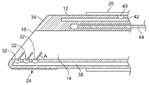
- FIG. 2A depicts a magnified view of a working end of the device of FIG. 1 .
- FIG. 2B shows a partial cross sectional view of a variation of a working end of a tissue dissection access device.
- FIGS. 3A to 3D show variations of different, dissecting surfaces for use with devices as described herein.
- FIG. 4A illustrates a variation of a tissue dissecting device coupled to a syringe and vacuum source.
- FIGS. 4B and 4C show irrigation and removal of fluids through ports in a working channel of a dissection access device.
- FIGS. 5A and 5B illustrate placement of a pair of devices within a body of a patient in an exemplary procedure to access a posterior region of the thoracic cavity.
- FIGS. 6A to 6Q show one exemplary use of the dissection access devices described herein to create bi-atrial lesion pattern on a posterior region of the heart.
- Methods and devices described herein provide for improved manipulation of organs and/or instruments within the body by creating working spaces within the body and adjacent to a target site. While the following disclosure discusses devices and methods for use in the thoracic cavity, such methods and devices can be applied to various body portions outside of the thoracic cavity. The methods and devices may allow for direct visualization along regions of anatomic structures not attainable with conventional approaches.
- the methods and devices described herein may be used in conjunction with, or as an alternative to the conventional approaches described herein.
- the surgical approaches and procedures described herein rely on entry through the diaphragm of a patient to access a regions of the thoracic cavity, the surgical approaches and procedures can be combined with various other access methods.
- FIG. 1 shows one example of a tissue dissection access device 10 configured to dissect tissue using a number of different tissue dissection modalities.
- devices according to the present invention that provide a number of dissection modalities, e.g., frictional dissection, wedge-type dissection, and dilation type dissection, provides a physician with a number of options to access a target site during a minimally invasive procedure.
- FIG. 1 shows a device with several tissue section modalities.
- certain variations of devices within the scope of this invention can have any sub-combination of tissue dissection modalities.
- the first dissection modality comprises a dilation wedge tip 22 or beveled tip located at the distal end of the cannula 12 .
- the wedge shaped tip provides a mechanical wedge dissection modality as the tip 22 can be inserted into small openings in tissue and where advancement of the tip 22 mechanically dilates the opening.
- the second dissection mode comprises a dissection surface 24 located on a side of the dilation wedge 22 .
- the dissection surface 24 provides a frictional or abrasion dissection modality as the physician is able to apply the tip to a tissue surface and gently dissect the tissue apart by relying upon the increased friction between the dissection surface 24 and the tissue.
- the dissection surface 24 can dissect tissue via axial movement relative to the tissue, by rotational movement, or a combination thereof.
- the dissection surface 24 can be configured to dissect tissue when moved in a single direction (as discussed below).
- the dissection surface 24 can be configured to catch tissue as it is pulled in a proximal direction. This allows distal advancement without resistance.
- the dissection surface 24 can be located on the cannula surface or even on a balloon dilation surface.
- the third dissection mode comprises an expandable dilation balloon member 26 located on a surface of the cannula 12 .
- the dilation balloon member can be a distensible or non-distensible balloon.
- the dilation balloon member 26 can be used to create a temporary cavity or to separate tissue to a greater degree than a diameter of the cannula 12 .
- Any number of expandable members can be used in place of a balloon (e.g., a mechanical basket, axially aligned flexible strands, an expandable helical wrapped ribbon or wire, etc.)
- FIG. 1 also shows another feature of certain devices that provides a physician with unobstructed access to tissue sites that are exposed by tissue dissection.
- the device 10 includes a cannula 12 having a working channel 14 extending therethrough and terminating at a distal opening 16 .
- the distal opening 16 is in-line with an axis of the working channel 14 .
- This feature provides an ability to extend a medical device through the working channel 14 and directly into or adjacent the tissue being dissected. Such a feature is very beneficial when using the working channel to visualize tissue being or using the working channel to advance a device therethrough to treat a tissue site that is exposed by dissected tissue.
- a physician can advance any such medical device from a proximal end 18 of the device 10 (as shown the device has an optional handle portion 20 on a proximal end) through the distal opening 16 and move the medical device relative to the distal opening 10 in alignment with an axis of the working channel 14 of the access device 10 .
- the handle can be configured to provide a textured surface to allow a physician to grip and manipulate the device.
- the cannula shaft (or the portion of the cannula 12 between the wedge tip 22 and the proximal portion 18 or handle portion 20 ) can be constructed to have a number of different configurations.
- the cannula shaft can be flexible such that it can be deflected from an axis of the distal opening 16 .
- the cannula shaft shall have a column strength that allows a physician to push or advance the device into tissue or between organs. In some cases, the flexibility of the shaft allows flexion when medical devices are placed therethrough. This can reduce forces placed on the target tissue.
- use of rigid medical devices placed within the working channel 14 can change the flexibility of the shaft to increase the ease by which the device 10 is remotely manipulated within the body.
- the cannula 12 can be fabricated front any variety of medical grade materials. In one variation, the cannula is constructed from either silicone or C-Flex.
- the device 10 also includes any number of fittings to couple the device to a fluid or vacuum source.
- the device 10 includes a first fluid connector 28 .
- the fluid connector 28 can be connected to a vacuum or fluid source to remove fluids from the working channel 14 of the device or deliver fluids to the working channel 14 .
- the fluid connector 28 can also be connected to a vacuum source and fluid source simultaneously via the use of a two way valve or similar type of flow diverters (e.g., a two way stop cock).
- a separate connector 30 can be provided to couple the dilation member 26 to a source of pressure (either air or fluid).
- FIG. 2A depicts a magnified view of a working end of the device 10 of FIG. 1 .
- the working channel 14 also includes a plurality of fluid ports 32 located therein.
- the fluid ports 32 are coupled to a fluid source for delivering a fluid to irrigate the target tissue or a medical device located within the working channel 14 .
- the fluid ports 32 also allow a physician to remove debris or fluid from the working channel 14 .
- fluid ports 32 there are a number of fluid ports 32 . Additional variations of the device include a single fluid port 32 . However, multiple fluid ports 32 provide an advantage to generate a larger area of fluid flow within the working channel 14 . Such a feature improves the ability of the device 10 to clean a medical device located therein by providing a greater area to deliver or remove fluid.
- the fluid ports 32 are located within the bevel of the dilation wedge 22 and are placed in alignment along an axis of the working channel 14 . However, the fluid ports 32 can also be arranged in a non-aligned manner or a random pattern.
- variations of the device 10 include fluid ports arranged on an exterior of the cannula 12 or proximal to the dilation ion wedge tip 12 within the working channel 14 .
- FIG. 2A also depicts additional aspects of the device 10 .
- the dilation wedge 22 comprises a transition surface 34 along the distal opening 16 that provides a smooth transition to the outer surface of the cannula 12 .
- This feature aids in dilating tissue from a small opening to a larger opening that is the size of the outer diameter of the cannula 12 .
- FIG. 2A shows another optional feature of a visualization element 36 located on a front face of the device 10 .
- Such elements can include a fiber optic scope or line as well as a CCD camera or any such visualization component as commonly known and used with various medical scopes.
- the working channel 14 and distal opening 16 are frequently depicted as having a circular cross section, variations of the device contemplate the working channel 14 and distal opening 16 to have non-cylindrical openings.
- the cross-sectional profile can include oval or rectangular shapes where a height and width of the channel are not equal. The benefit of such configurations is that multiple devices can be advanced parallel within the working channel.
- FIG. 2B shows a partial cross sectional view of a variation of a working end of a device 10 according to the present invention.
- the device 10 includes a plurality of fluid lumens 38 , 42 coupled to respective fluid ports 32 , 40 .
- fluid ports 32 can be placed in fluid communication with the working channel 14 to irrigate and remove fluids to or from the channel 14 for the clearing of debris from medical devices advanced within the working channel 14 .
- One or more fluid ports 40 also can be placed within the expandable dilation member 26 for pressurization of the member 26 to dissect or separate tissue.
- the fluid ports 32 located within the working channel 14 are angled or directed towards a proximal end of the device 10 (e.g., such that an axis of the port 32 forms an angle A that is less than 90 degrees. Directing the ports 32 in such a manner permits fluid to be delivered to the face of any device advanced within the working channel.
- FIG. 2B also shows an optional support member 44 located within a wall of the cannula 12 .
- the support member can be rigid or shapeable.
- a malleable or shapeable support 44 may be incorporated into a portion or an entirety of the cannula 12 to allow shaping the member into a desired configuration.
- the shape is selected to improve the ability of the device to direct the scope and instruments towards the desired site within the body (e.g., a region of the surface of the heart, or other anatomic structure).
- the support 44 can be placed in a support lumen such that the support 44 is slidable within the support lumen of the cannula 12 .
- the support 44 can be removable from the cannula 12 .
- the device will not be constructed to have a support member 44 or will not have the visualization element 36 shown in FIG. 2A .
- FIGS. 3A to 3D show variations of different dissecting surfaces 24 for use with devices as described herein.
- a device can be equipped with more than one type of dissecting surface 24 .
- a dissecting surface 24 can be placed on any portion of the device (including the expandable dilation member 26 ).
- the figures illustrate the dissecting surfaces 24 on the bottom edge of the cannula 12 , the dissecting surfaces can extend over a full or partial perimeter of the cannula surface 12 .
- FIG. 3A shows a variation of a dissecting surface 24 that comprises a layer of material, such as a polymeric layer, a layer of cloth, or other surgical material that is textured and can be used to abraid tissue for dissection
- the material can comprise an absorbable surgical sponge material, such as gauze or other woven cotton.
- the material can be comprised of a polymeric material that is inserted into or onto the cannula 12 where the polymeric material comprises a sufficiently high coefficient of friction that the nature of rubbing the material against tissue results in abrasion and dissection of the tissue. The texture of the material abrades the tissue being dissected so that the dissection can be performed in either a distal or proximal motion of the cannula 12 .
- the cannula 12 can have a relief section removed for insertion of the material 24 .
- the material can be affixed, to an exterior of the device.
- the material is non-absorbent and retains texture and stiffness as it encounters body tissue and fluids.
- the material can be glued onto the cannula 12 or the cannula 12 can have a textured or sharp surface to retain the material.
- FIG. 3B shows another variation of a dissection surface 24 .
- the dissection surface 24 is formed directly into the surface of the cannula 12 via as mechanical or chemical process.
- the cannula 12 can be grounded, etched, swaged, head-blasted, heat formed, etc.
- the textured dissection surface 24 could be formed in a mold such that the dissection surface 24 is directly molded onto the cannula 12 .
- FIG. 3C shows another variation of a dissection surface 24 formed from a plurality of surfaces that extend from a surface of the cannula 12 .
- the surface 24 can be formed from granules deposited on the cannula 12 to form a sand-paper like coating.
- the surface 24 can comprise flexible extensions that engage and grip tissue when moved across the tissue.
- FIG. 3D shows yet another variation of a dissecting surface 24 .
- the dissecting surface 24 comprises a directional dissecting surface 24 as shown by the saw-tooth configuration.
- the dissecting surface 24 generally does not engage the tissue when moved in a first direction (in this case a distal direction) but engages tissue when moved in a second direction (in this case a proximal direction).
- FIG. 4A illustrates a variation of a tissue dissecting device 10 coupled to a syringe 46 via a connector 28 .
- the device 10 can be simultaneously coupled to a vacuum source 48 via a two way valve.
- the device 10 can accommodate a scope or medical device 50 such as an ablation device. Regardless of the medical device, as the tissue dissecting device 10 dissects tissue, various bodily debris and fluid often attach to the medical device advanced therethrough. In the case of a scope, the debris and fluid can prevent the scope from providing a clear image to the physician. In the case of energy delivery devices, debris attached to an energy transfer element can affect the energy transfer that should otherwise occur.
- FIG. 4B injection of fluid through the fluid lumen 38 and fluid ports 32 into the working channel 14 bathes the end (or other area as appropriate) of the medical device 50 removing the debris and cleaning the device 50 .
- FIG. 4C shows a state of the device 10 where suction is applied through the fluid lumen 38 to draw fluid and other debris into the fluid ports 32 . Placement of the fluid ports 32 within the working channel 14 .
- FIGS. 5A and 5B illustrate placement of a pair of devices 10 within a body 100 of a patient in an exemplary procedure. It is noted that the device 10 can be used in any part of the body and through any incision or port in a minimally invasive manner. However, the device 10 can also be used in open surgical procedures.
- FIG. 5A illustrates creation of two incisions 102 104 in the body 100 .
- the incisions are made in the abdomen of the patient so that the dissecting access devices 10 , 11 can then pass through a diaphragm of the patient to a posterior side of the thoracic cavity (as shown in FIG. 5B ).
- FIGS. 6A to 6Q show one example where the device accesses a posterior surface of the heart 106 and where the multi-mode dissection attributes of the device enable a bi-atrial lesion pattern on a posterior region of the heart. Since the view is from a posterior surface, the notations of right and left are reversed.
- the devices 10 are advanced through an epicardium using a left incision 120 and a right incision 122 . This allows a distal opening 16 of the devices 10 , 11 to be placed into the pericardal space around the left atrium 124 .
- a catheter 60 (such as a Foley catheter) passes from the right access device 11 to allow a guidewire 62 to be advanced over the left atrium 124 .
- the guidewire 62 is then retrieved into the left cannula 10 using a set of graspers or other similar device.
- the guidewire 62 passes between the left 11 and right 10 access devices and ultimately extends out of the proximal ends of the access devices 10 11 .
- a medical device 64 (such as an ablation device) is advanced over the guidewire 62 and through the right access device 11 .
- the end of the medical device 64 can be optionally viewed with a flexible scope, such as an endoscope or bronchoscope 66 which is also placed over the guidewire 62 from the left access device 10 .
- the medical device 64 can be any energy delivery, ablation, or coagulation device that may be advanced through the access device. Examples of coagulation devices that adhere to irregular contoured surfaces are disclosed below.
- the access device 64 can be advanced over the wire 62 , to form coagulation lines 150 and 151 on the left atrium (as shown by FIG. 6E ).
- Coagulation line 152 can be created by manipulating the right access device 11 and pulling the device back towards the right access device 11 .
- FIG. 6F shows repositioning of the right access device 11 with a rigid scope 68 placed therethrough.
- the combination as well as the features of the device described herein permit dissection through the first pericardial reflection 126 in front of Watterson's groove 128 .
- the scope allows the surgeon to visually navigate through the space as the access device 11 dissects the pericardial reflection 126 . This may be accomplished by rotation of the access device 11 , which allows a dissection surface to gently dissect the pericardial reflection 126 .
- the cannula can advance into Watterson's groove 128 and used to dissect additional tissue to create space for the medical device (coagulation or ablation device). The physician can then advance the access device 11 to further dissect a second pericardial reflection 130 leading into the transverse sinus 132 .
- FIG. 6H shows a catheter 60 advanced into transverse sinus 132 .
- a larger sized access device 13 or regular cannula can be placed through the left incision 120 for securing a guidewire 62 placed in the Foley catheter (as shown in FIG. 6I ).
- the larger cannula allows both a rigid scope as well as a grasping instrument to be placed within the cannula 13 for viewing and securing the guidewire 62 .
- FIG. 6J shows the site once the guidewire 62 extends around the pulmonary veins 108 and extends out of the body.
- the physician can then advance a treatment device 64 over the guidewire 62 from the right incision 122 and a flexible scope 66 advances over the guidewire 62 from the left incision 122 . This permits the physician to view the end of the treatment device 64 .
- the physician can then advance treatment device 64 and scope 66 around the guidewire 62 to create coagulation lesions 153 , 154 , and 155 (in that order, where lesions 153 and 155 cross lesions 151 and 152 .
- This set of lesions, along with lesions 150 , 151 , and 152 isolates the pulmonary veins from the remainder of the atrium 124 (as shown in FIG. 6K ).
- the flexible scope 66 can remain within the transverse sinus 132 and the guidewire 62 can be pulled back into the flexible scope—leaving the tip of the guidewire 62 visible to the scope 66 .
- the physician can then advance the scope 66 and guidewire 62 through the pericardial reflection 130 that was previously dissected and over to the right atrium 134 .
- an access device 11 can be inserted to view and accept the end of the guidewire over the right atrium 134 .
- the access device 11 can be placed either through the previously made right incision 122 or through another higher incision 136 in the pericardium that is over the right atrium 134 .
- the physician then advances the guidewire 62 until an end advances out of a proximal end of the access device 11 .
- the treatment device 64 can be positioned using the guidewire 62 to create the first coagulation lesion 156 on the right atrium 134 (as shown in FIGS. 6N and 6O )
- the physician removes the guidewire 62 from the patient and two access devices 10 and 11 are inserted into either incision in the pericardium 122 or 136 .
- the physician situates the tips of the access devices 10 and 11 over the right atrium 134 as shown in FIG. 6P .
- the physician may need to further dissect the pericardial reflection 126 on the right atrium with access device 10 .
- the physician passes a guidewire 62 between access devices.
- a Foley catheter, grasper or an such device can be used to assist in passing the guidewire.
- the physician places the treatment device 64 and the scope 66 through a separate access device 10 and 11 .
- the treatment device 64 and scope 66 can be placed through either access device 10 and 11 depending on the desired location of the coagulation lesion.
- the physician can then create the final coagulation lesion 157 as shown in FIG. 6R .
- the final coagulation lesions 156 and 157 each cross the previously made lesions on the left atrium 124 creating the pattern as shown.
- the integrated vacuum coagulation probes provided by nContact Surgical, Inc., North Carolina are examples of devices that allow intimate contact specifically between a soft tissue surface and the energy portion of the device.
- the electrode(s) used to transmit energy is capable of heating the soft tissue until achieving irreversible injury making the soft tissue non-viable and unable to propagate electrical impulses, mutate, or reproduce.
- These integrated vacuum coagulation probe embodiments may be in conjunction with the access devices described herein to treat atrial fibrillation, ventricular tachycardia or other arrhythmia substrate, or eliminating cancer in lung, or other soft thoracic tissue by destroying target cells.
- these integrated vacuum coagulation devices may be used to heat soft tissue along the posterior heart surface resulting in heat-induced contraction of collagen in such tissue thereby resulting shrinking of said soft tissue.
- heating the mitral valve annulus along the posterior atrioventricular groove may induce shrinking of the annulus thereby correcting mitral valve regurgitation.
- the invention is not limited to the above described vacuum coagulation probes. Instead, any number of coagulation, ablation, or surgical devices may be used as required.
Abstract
Description
Claims (44)
Priority Applications (1)
| Application Number | Priority Date | Filing Date | Title |
|---|---|---|---|
| US14/668,479 US9931132B2 (en) | 2008-06-12 | 2015-03-25 | Dissecting cannula and methods of use thereof |
Applications Claiming Priority (4)
| Application Number | Priority Date | Filing Date | Title |
|---|---|---|---|
| US6110108P | 2008-06-12 | 2008-06-12 | |
| US12/174,549 US8267951B2 (en) | 2008-06-12 | 2008-07-16 | Dissecting cannula and methods of use thereof |
| US13/587,692 US8992557B2 (en) | 2008-06-12 | 2012-08-16 | Dissecting cannula and methods of use thereof |
| US14/668,479 US9931132B2 (en) | 2008-06-12 | 2015-03-25 | Dissecting cannula and methods of use thereof |
Related Parent Applications (1)
| Application Number | Title | Priority Date | Filing Date |
|---|---|---|---|
| US13/587,692 Continuation US8992557B2 (en) | 2008-06-12 | 2012-08-16 | Dissecting cannula and methods of use thereof |
Publications (2)
| Publication Number | Publication Date |
|---|---|
| US20150196316A1 US20150196316A1 (en) | 2015-07-16 |
| US9931132B2 true US9931132B2 (en) | 2018-04-03 |
Family
ID=41415467
Family Applications (3)
| Application Number | Title | Priority Date | Filing Date |
|---|---|---|---|
| US12/174,549 Active 2031-04-20 US8267951B2 (en) | 2008-06-12 | 2008-07-16 | Dissecting cannula and methods of use thereof |
| US13/587,692 Active 2028-11-12 US8992557B2 (en) | 2008-06-12 | 2012-08-16 | Dissecting cannula and methods of use thereof |
| US14/668,479 Active 2029-06-30 US9931132B2 (en) | 2008-06-12 | 2015-03-25 | Dissecting cannula and methods of use thereof |
Family Applications Before (2)
| Application Number | Title | Priority Date | Filing Date |
|---|---|---|---|
| US12/174,549 Active 2031-04-20 US8267951B2 (en) | 2008-06-12 | 2008-07-16 | Dissecting cannula and methods of use thereof |
| US13/587,692 Active 2028-11-12 US8992557B2 (en) | 2008-06-12 | 2012-08-16 | Dissecting cannula and methods of use thereof |
Country Status (3)
| Country | Link |
|---|---|
| US (3) | US8267951B2 (en) |
| EP (1) | EP2303154A4 (en) |
| WO (1) | WO2009152173A1 (en) |
Cited By (1)
| Publication number | Priority date | Publication date | Assignee | Title |
|---|---|---|---|---|
| US11678928B2 (en) | 2019-01-10 | 2023-06-20 | Atricure, Inc. | Surgical clamp |
Families Citing this family (500)
| Publication number | Priority date | Publication date | Assignee | Title |
|---|---|---|---|---|
| US9060770B2 (en) | 2003-05-20 | 2015-06-23 | Ethicon Endo-Surgery, Inc. | Robotically-driven surgical instrument with E-beam driver |
| US20070084897A1 (en) | 2003-05-20 | 2007-04-19 | Shelton Frederick E Iv | Articulating surgical stapling instrument incorporating a two-piece e-beam firing mechanism |
| US11896225B2 (en) | 2004-07-28 | 2024-02-13 | Cilag Gmbh International | Staple cartridge comprising a pan |
| US8215531B2 (en) | 2004-07-28 | 2012-07-10 | Ethicon Endo-Surgery, Inc. | Surgical stapling instrument having a medical substance dispenser |
| US9186175B2 (en) | 2004-10-28 | 2015-11-17 | Nico Corporation | Surgical access assembly and method of using same |
| US9387010B2 (en) * | 2004-10-28 | 2016-07-12 | Nico Corporation | Surgical access assembly and method of using same |
| EP1909655A2 (en) | 2005-06-20 | 2008-04-16 | Sutura, Inc. | Method and apparatus for applying a knot to a suture |
| US10159482B2 (en) | 2005-08-31 | 2018-12-25 | Ethicon Llc | Fastener cartridge assembly comprising a fixed anvil and different staple heights |
| US11484312B2 (en) | 2005-08-31 | 2022-11-01 | Cilag Gmbh International | Staple cartridge comprising a staple driver arrangement |
| US7934630B2 (en) | 2005-08-31 | 2011-05-03 | Ethicon Endo-Surgery, Inc. | Staple cartridges for forming staples having differing formed staple heights |
| US7669746B2 (en) | 2005-08-31 | 2010-03-02 | Ethicon Endo-Surgery, Inc. | Staple cartridges for forming staples having differing formed staple heights |
| US9237891B2 (en) | 2005-08-31 | 2016-01-19 | Ethicon Endo-Surgery, Inc. | Robotically-controlled surgical stapling devices that produce formed staples having different lengths |
| US11246590B2 (en) | 2005-08-31 | 2022-02-15 | Cilag Gmbh International | Staple cartridge including staple drivers having different unfired heights |
| US20070194079A1 (en) | 2005-08-31 | 2007-08-23 | Hueil Joseph C | Surgical stapling device with staple drivers of different height |
| US20070106317A1 (en) | 2005-11-09 | 2007-05-10 | Shelton Frederick E Iv | Hydraulically and electrically actuated articulation joints for surgical instruments |
| US8708213B2 (en) | 2006-01-31 | 2014-04-29 | Ethicon Endo-Surgery, Inc. | Surgical instrument having a feedback system |
| US20120292367A1 (en) | 2006-01-31 | 2012-11-22 | Ethicon Endo-Surgery, Inc. | Robotically-controlled end effector |
| US20110006101A1 (en) | 2009-02-06 | 2011-01-13 | EthiconEndo-Surgery, Inc. | Motor driven surgical fastener device with cutting member lockout arrangements |
| US8820603B2 (en) | 2006-01-31 | 2014-09-02 | Ethicon Endo-Surgery, Inc. | Accessing data stored in a memory of a surgical instrument |
| US7845537B2 (en) | 2006-01-31 | 2010-12-07 | Ethicon Endo-Surgery, Inc. | Surgical instrument having recording capabilities |
| US20110290856A1 (en) | 2006-01-31 | 2011-12-01 | Ethicon Endo-Surgery, Inc. | Robotically-controlled surgical instrument with force-feedback capabilities |
| US11793518B2 (en) | 2006-01-31 | 2023-10-24 | Cilag Gmbh International | Powered surgical instruments with firing system lockout arrangements |
| US20110024477A1 (en) | 2009-02-06 | 2011-02-03 | Hall Steven G | Driven Surgical Stapler Improvements |
| US11278279B2 (en) | 2006-01-31 | 2022-03-22 | Cilag Gmbh International | Surgical instrument assembly |
| US7753904B2 (en) | 2006-01-31 | 2010-07-13 | Ethicon Endo-Surgery, Inc. | Endoscopic surgical instrument with a handle that can articulate with respect to the shaft |
| US8186555B2 (en) | 2006-01-31 | 2012-05-29 | Ethicon Endo-Surgery, Inc. | Motor-driven surgical cutting and fastening instrument with mechanical closure system |
| US11224427B2 (en) | 2006-01-31 | 2022-01-18 | Cilag Gmbh International | Surgical stapling system including a console and retraction assembly |
| US9861359B2 (en) | 2006-01-31 | 2018-01-09 | Ethicon Llc | Powered surgical instruments with firing system lockout arrangements |
| US8236010B2 (en) | 2006-03-23 | 2012-08-07 | Ethicon Endo-Surgery, Inc. | Surgical fastener and cutter with mimicking end effector |
| US8992422B2 (en) | 2006-03-23 | 2015-03-31 | Ethicon Endo-Surgery, Inc. | Robotically-controlled endoscopic accessory channel |
| US8322455B2 (en) | 2006-06-27 | 2012-12-04 | Ethicon Endo-Surgery, Inc. | Manually driven surgical cutting and fastening instrument |
| US10130359B2 (en) | 2006-09-29 | 2018-11-20 | Ethicon Llc | Method for forming a staple |
| US7506791B2 (en) | 2006-09-29 | 2009-03-24 | Ethicon Endo-Surgery, Inc. | Surgical stapling instrument with mechanical mechanism for limiting maximum tissue compression |
| US10568652B2 (en) | 2006-09-29 | 2020-02-25 | Ethicon Llc | Surgical staples having attached drivers of different heights and stapling instruments for deploying the same |
| US8684253B2 (en) | 2007-01-10 | 2014-04-01 | Ethicon Endo-Surgery, Inc. | Surgical instrument with wireless communication between a control unit of a robotic system and remote sensor |
| US11291441B2 (en) | 2007-01-10 | 2022-04-05 | Cilag Gmbh International | Surgical instrument with wireless communication between control unit and remote sensor |
| US8652120B2 (en) | 2007-01-10 | 2014-02-18 | Ethicon Endo-Surgery, Inc. | Surgical instrument with wireless communication between control unit and sensor transponders |
| US11039836B2 (en) | 2007-01-11 | 2021-06-22 | Cilag Gmbh International | Staple cartridge for use with a surgical stapling instrument |
| US8701958B2 (en) | 2007-01-11 | 2014-04-22 | Ethicon Endo-Surgery, Inc. | Curved end effector for a surgical stapling device |
| US20090001130A1 (en) | 2007-03-15 | 2009-01-01 | Hess Christopher J | Surgical procedure using a cutting and stapling instrument having releasable staple-forming pockets |
| US8893946B2 (en) | 2007-03-28 | 2014-11-25 | Ethicon Endo-Surgery, Inc. | Laparoscopic tissue thickness and clamp load measuring devices |
| US8246636B2 (en) | 2007-03-29 | 2012-08-21 | Nobles Medical Technologies, Inc. | Suturing devices and methods for closing a patent foramen ovale |
| US11857181B2 (en) | 2007-06-04 | 2024-01-02 | Cilag Gmbh International | Robotically-controlled shaft based rotary drive systems for surgical instruments |
| US8931682B2 (en) | 2007-06-04 | 2015-01-13 | Ethicon Endo-Surgery, Inc. | Robotically-controlled shaft based rotary drive systems for surgical instruments |
| US7753245B2 (en) | 2007-06-22 | 2010-07-13 | Ethicon Endo-Surgery, Inc. | Surgical stapling instruments |
| US8408439B2 (en) | 2007-06-22 | 2013-04-02 | Ethicon Endo-Surgery, Inc. | Surgical stapling instrument with an articulatable end effector |
| US11849941B2 (en) | 2007-06-29 | 2023-12-26 | Cilag Gmbh International | Staple cartridge having staple cavities extending at a transverse angle relative to a longitudinal cartridge axis |
| US7905381B2 (en) | 2008-09-19 | 2011-03-15 | Ethicon Endo-Surgery, Inc. | Surgical stapling instrument with cutting member arrangement |
| US8561870B2 (en) | 2008-02-13 | 2013-10-22 | Ethicon Endo-Surgery, Inc. | Surgical stapling instrument |
| US9179912B2 (en) | 2008-02-14 | 2015-11-10 | Ethicon Endo-Surgery, Inc. | Robotically-controlled motorized surgical cutting and fastening instrument |
| US7819298B2 (en) | 2008-02-14 | 2010-10-26 | Ethicon Endo-Surgery, Inc. | Surgical stapling apparatus with control features operable with one hand |
| BRPI0901282A2 (en) | 2008-02-14 | 2009-11-17 | Ethicon Endo Surgery Inc | surgical cutting and fixation instrument with rf electrodes |
| US7866527B2 (en) | 2008-02-14 | 2011-01-11 | Ethicon Endo-Surgery, Inc. | Surgical stapling apparatus with interlockable firing system |
| US8573465B2 (en) | 2008-02-14 | 2013-11-05 | Ethicon Endo-Surgery, Inc. | Robotically-controlled surgical end effector system with rotary actuated closure systems |
| US8758391B2 (en) | 2008-02-14 | 2014-06-24 | Ethicon Endo-Surgery, Inc. | Interchangeable tools for surgical instruments |
| US8657174B2 (en) | 2008-02-14 | 2014-02-25 | Ethicon Endo-Surgery, Inc. | Motorized surgical cutting and fastening instrument having handle based power source |
| US8636736B2 (en) | 2008-02-14 | 2014-01-28 | Ethicon Endo-Surgery, Inc. | Motorized surgical cutting and fastening instrument |
| US11272927B2 (en) | 2008-02-15 | 2022-03-15 | Cilag Gmbh International | Layer arrangements for surgical staple cartridges |
| US9615826B2 (en) | 2010-09-30 | 2017-04-11 | Ethicon Endo-Surgery, Llc | Multiple thickness implantable layers for surgical stapling devices |
| US8858528B2 (en) | 2008-04-23 | 2014-10-14 | Ncontact Surgical, Inc. | Articulating cannula access device |
| WO2009137766A1 (en) | 2008-05-09 | 2009-11-12 | Sutura, Inc. | Suturing devices and methods for suturing an anatomic valve |
| US8267951B2 (en) | 2008-06-12 | 2012-09-18 | Ncontact Surgical, Inc. | Dissecting cannula and methods of use thereof |
| PL3476312T3 (en) | 2008-09-19 | 2024-03-11 | Ethicon Llc | Surgical stapler with apparatus for adjusting staple height |
| US9005230B2 (en) | 2008-09-23 | 2015-04-14 | Ethicon Endo-Surgery, Inc. | Motorized surgical instrument |
| US8210411B2 (en) | 2008-09-23 | 2012-07-03 | Ethicon Endo-Surgery, Inc. | Motor-driven surgical cutting instrument |
| US11648005B2 (en) | 2008-09-23 | 2023-05-16 | Cilag Gmbh International | Robotically-controlled motorized surgical instrument with an end effector |
| US9386983B2 (en) | 2008-09-23 | 2016-07-12 | Ethicon Endo-Surgery, Llc | Robotically-controlled motorized surgical instrument |
| US8608045B2 (en) | 2008-10-10 | 2013-12-17 | Ethicon Endo-Sugery, Inc. | Powered surgical cutting and stapling apparatus with manually retractable firing system |
| US8517239B2 (en) | 2009-02-05 | 2013-08-27 | Ethicon Endo-Surgery, Inc. | Surgical stapling instrument comprising a magnetic element driver |
| EP2393430A1 (en) | 2009-02-06 | 2011-12-14 | Ethicon Endo-Surgery, Inc. | Driven surgical stapler improvements |
| US8444036B2 (en) | 2009-02-06 | 2013-05-21 | Ethicon Endo-Surgery, Inc. | Motor driven surgical fastener device with mechanisms for adjusting a tissue gap within the end effector |
| US8851354B2 (en) | 2009-12-24 | 2014-10-07 | Ethicon Endo-Surgery, Inc. | Surgical cutting instrument that analyzes tissue thickness |
| US8220688B2 (en) | 2009-12-24 | 2012-07-17 | Ethicon Endo-Surgery, Inc. | Motor-driven surgical cutting instrument with electric actuator directional control assembly |
| KR20120123065A (en) * | 2009-12-30 | 2012-11-07 | 에이엠에스 리써치 코오포레이션 | Systems, implants, tools, and methods for treatments of pelvic conditions |
| DK2582314T3 (en) | 2010-06-15 | 2020-03-02 | Avenu Medical Inc | INTRAVASCULAR ARTERIAL TO VENOUS ANASTOMOSIS AND TISSUE WELDING CATHETER |
| US8783543B2 (en) | 2010-07-30 | 2014-07-22 | Ethicon Endo-Surgery, Inc. | Tissue acquisition arrangements and methods for surgical stapling devices |
| US9364233B2 (en) | 2010-09-30 | 2016-06-14 | Ethicon Endo-Surgery, Llc | Tissue thickness compensators for circular surgical staplers |
| US9386988B2 (en) | 2010-09-30 | 2016-07-12 | Ethicon End-Surgery, LLC | Retainer assembly including a tissue thickness compensator |
| US11925354B2 (en) | 2010-09-30 | 2024-03-12 | Cilag Gmbh International | Staple cartridge comprising staples positioned within a compressible portion thereof |
| US9277919B2 (en) | 2010-09-30 | 2016-03-08 | Ethicon Endo-Surgery, Llc | Tissue thickness compensator comprising fibers to produce a resilient load |
| US9307989B2 (en) | 2012-03-28 | 2016-04-12 | Ethicon Endo-Surgery, Llc | Tissue stapler having a thickness compensator incorportating a hydrophobic agent |
| US9211120B2 (en) | 2011-04-29 | 2015-12-15 | Ethicon Endo-Surgery, Inc. | Tissue thickness compensator comprising a plurality of medicaments |
| US10945731B2 (en) | 2010-09-30 | 2021-03-16 | Ethicon Llc | Tissue thickness compensator comprising controlled release and expansion |
| US9314246B2 (en) | 2010-09-30 | 2016-04-19 | Ethicon Endo-Surgery, Llc | Tissue stapler having a thickness compensator incorporating an anti-inflammatory agent |
| US20120080336A1 (en) | 2010-09-30 | 2012-04-05 | Ethicon Endo-Surgery, Inc. | Staple cartridge comprising staples positioned within a compressible portion thereof |
| US9414838B2 (en) | 2012-03-28 | 2016-08-16 | Ethicon Endo-Surgery, Llc | Tissue thickness compensator comprised of a plurality of materials |
| US9332974B2 (en) | 2010-09-30 | 2016-05-10 | Ethicon Endo-Surgery, Llc | Layered tissue thickness compensator |
| US11298125B2 (en) | 2010-09-30 | 2022-04-12 | Cilag Gmbh International | Tissue stapler having a thickness compensator |
| US9220501B2 (en) | 2010-09-30 | 2015-12-29 | Ethicon Endo-Surgery, Inc. | Tissue thickness compensators |
| EP2621356B1 (en) | 2010-09-30 | 2018-03-07 | Ethicon LLC | Fastener system comprising a retention matrix and an alignment matrix |
| US9055941B2 (en) | 2011-09-23 | 2015-06-16 | Ethicon Endo-Surgery, Inc. | Staple cartridge including collapsible deck |
| US9517063B2 (en) | 2012-03-28 | 2016-12-13 | Ethicon Endo-Surgery, Llc | Movable member for use with a tissue thickness compensator |
| US10405854B2 (en) | 2010-09-30 | 2019-09-10 | Ethicon Llc | Surgical stapling cartridge with layer retention features |
| US9301753B2 (en) | 2010-09-30 | 2016-04-05 | Ethicon Endo-Surgery, Llc | Expandable tissue thickness compensator |
| US9629814B2 (en) | 2010-09-30 | 2017-04-25 | Ethicon Endo-Surgery, Llc | Tissue thickness compensator configured to redistribute compressive forces |
| US11812965B2 (en) | 2010-09-30 | 2023-11-14 | Cilag Gmbh International | Layer of material for a surgical end effector |
| US8695866B2 (en) | 2010-10-01 | 2014-04-15 | Ethicon Endo-Surgery, Inc. | Surgical instrument having a power control circuit |
| CN106388888B (en) | 2011-04-15 | 2019-12-27 | 心脏缝合有限公司 | Suturing device and method for suturing an anatomical valve |
| CA2834649C (en) | 2011-04-29 | 2021-02-16 | Ethicon Endo-Surgery, Inc. | Staple cartridge comprising staples positioned within a compressible portion thereof |
| US9072535B2 (en) | 2011-05-27 | 2015-07-07 | Ethicon Endo-Surgery, Inc. | Surgical stapling instruments with rotatable staple deployment arrangements |
| US11207064B2 (en) | 2011-05-27 | 2021-12-28 | Cilag Gmbh International | Automated end effector component reloading system for use with a robotic system |
| US9050084B2 (en) | 2011-09-23 | 2015-06-09 | Ethicon Endo-Surgery, Inc. | Staple cartridge including collapsible deck arrangement |
| US9114202B1 (en) * | 2011-11-15 | 2015-08-25 | Bionix Development Corporation | Lighted suction device |
| US8728090B2 (en) * | 2012-01-12 | 2014-05-20 | Mohamad Farhadi | Tonsillar suction dissector |
| US9948835B2 (en) * | 2012-01-31 | 2018-04-17 | Siemens Energy, Inc. | Single-axis inspection scope with spherical camera and method for internal inspection of power generation machinery |
| US9778141B2 (en) * | 2012-01-31 | 2017-10-03 | Siemens Energy, Inc. | Video inspection system with deformable, self-supporting deployment tether |
| EP2812063B1 (en) | 2012-02-08 | 2020-03-25 | Avenu Medical, Inc. | Intravascular arterial to venous anastomosis and tissue welding catheter |
| US9044230B2 (en) | 2012-02-13 | 2015-06-02 | Ethicon Endo-Surgery, Inc. | Surgical cutting and fastening instrument with apparatus for determining cartridge and firing motion status |
| MX350846B (en) | 2012-03-28 | 2017-09-22 | Ethicon Endo Surgery Inc | Tissue thickness compensator comprising capsules defining a low pressure environment. |
| US9198662B2 (en) | 2012-03-28 | 2015-12-01 | Ethicon Endo-Surgery, Inc. | Tissue thickness compensator having improved visibility |
| CN104321024B (en) | 2012-03-28 | 2017-05-24 | 伊西康内外科公司 | Tissue thickness compensator comprising a plurality of layers |
| RU2644272C2 (en) | 2012-03-28 | 2018-02-08 | Этикон Эндо-Серджери, Инк. | Limitation node with tissue thickness compensator |
| US9592069B2 (en) | 2012-04-28 | 2017-03-14 | Physcient, Inc. | Methods and devices for soft tissue dissection |
| EP2840982B1 (en) | 2012-04-28 | 2017-07-26 | Physcient, Inc. | Devices for soft tissue dissection |
| EP3597115A1 (en) * | 2012-05-11 | 2020-01-22 | Heartstitch, Inc. | Suturing devices for suturing an anatomic structure |
| US9101358B2 (en) | 2012-06-15 | 2015-08-11 | Ethicon Endo-Surgery, Inc. | Articulatable surgical instrument comprising a firing drive |
| RU2636861C2 (en) | 2012-06-28 | 2017-11-28 | Этикон Эндо-Серджери, Инк. | Blocking of empty cassette with clips |
| US9204879B2 (en) | 2012-06-28 | 2015-12-08 | Ethicon Endo-Surgery, Inc. | Flexible drive member |
| US9561038B2 (en) | 2012-06-28 | 2017-02-07 | Ethicon Endo-Surgery, Llc | Interchangeable clip applier |
| US9028494B2 (en) | 2012-06-28 | 2015-05-12 | Ethicon Endo-Surgery, Inc. | Interchangeable end effector coupling arrangement |
| US9289256B2 (en) | 2012-06-28 | 2016-03-22 | Ethicon Endo-Surgery, Llc | Surgical end effectors having angled tissue-contacting surfaces |
| BR112014032776B1 (en) | 2012-06-28 | 2021-09-08 | Ethicon Endo-Surgery, Inc | SURGICAL INSTRUMENT SYSTEM AND SURGICAL KIT FOR USE WITH A SURGICAL INSTRUMENT SYSTEM |
| US9101385B2 (en) | 2012-06-28 | 2015-08-11 | Ethicon Endo-Surgery, Inc. | Electrode connections for rotary driven surgical tools |
| US9649111B2 (en) | 2012-06-28 | 2017-05-16 | Ethicon Endo-Surgery, Llc | Replaceable clip cartridge for a clip applier |
| US9226751B2 (en) | 2012-06-28 | 2016-01-05 | Ethicon Endo-Surgery, Inc. | Surgical instrument system including replaceable end effectors |
| US11278284B2 (en) | 2012-06-28 | 2022-03-22 | Cilag Gmbh International | Rotary drive arrangements for surgical instruments |
| US9072536B2 (en) | 2012-06-28 | 2015-07-07 | Ethicon Endo-Surgery, Inc. | Differential locking arrangements for rotary powered surgical instruments |
| US9119657B2 (en) | 2012-06-28 | 2015-09-01 | Ethicon Endo-Surgery, Inc. | Rotary actuatable closure arrangement for surgical end effector |
| US20140001231A1 (en) | 2012-06-28 | 2014-01-02 | Ethicon Endo-Surgery, Inc. | Firing system lockout arrangements for surgical instruments |
| US9125662B2 (en) | 2012-06-28 | 2015-09-08 | Ethicon Endo-Surgery, Inc. | Multi-axis articulating and rotating surgical tools |
| AU2013344595B2 (en) | 2012-11-14 | 2017-09-28 | Avenu Medical, Inc. | Intravascular arterial to venous anastomosis and tissue welding catheter |
| US9386984B2 (en) | 2013-02-08 | 2016-07-12 | Ethicon Endo-Surgery, Llc | Staple cartridge comprising a releasable cover |
| US20140246475A1 (en) | 2013-03-01 | 2014-09-04 | Ethicon Endo-Surgery, Inc. | Control methods for surgical instruments with removable implement portions |
| BR112015021098B1 (en) | 2013-03-01 | 2022-02-15 | Ethicon Endo-Surgery, Inc | COVERAGE FOR A JOINT JOINT AND SURGICAL INSTRUMENT |
| RU2669463C2 (en) | 2013-03-01 | 2018-10-11 | Этикон Эндо-Серджери, Инк. | Surgical instrument with soft stop |
| US20140263552A1 (en) | 2013-03-13 | 2014-09-18 | Ethicon Endo-Surgery, Inc. | Staple cartridge tissue thickness sensor system |
| US9332987B2 (en) | 2013-03-14 | 2016-05-10 | Ethicon Endo-Surgery, Llc | Control arrangements for a drive member of a surgical instrument |
| US9629629B2 (en) | 2013-03-14 | 2017-04-25 | Ethicon Endo-Surgey, LLC | Control systems for surgical instruments |
| US20150257743A1 (en) * | 2013-03-15 | 2015-09-17 | James W. Meador | Pericardial access device |
| US9604041B2 (en) * | 2013-03-15 | 2017-03-28 | Acclarent, Inc. | Nasal fluid management device |
| AU2014233486B2 (en) * | 2013-03-15 | 2018-11-15 | DePuy Synthes Products, Inc. | Viewing trocar with integrated prism for use with angled endoscope |
| US9408955B2 (en) | 2013-03-15 | 2016-08-09 | Acclarent, Inc. | Nasal fluid management device |
| US9408756B2 (en) | 2013-03-15 | 2016-08-09 | Acclarent, Inc. | Nasal fluid management device |
| US9332984B2 (en) | 2013-03-27 | 2016-05-10 | Ethicon Endo-Surgery, Llc | Fastener cartridge assemblies |
| US9795384B2 (en) | 2013-03-27 | 2017-10-24 | Ethicon Llc | Fastener cartridge comprising a tissue thickness compensator and a gap setting element |
| US9572577B2 (en) | 2013-03-27 | 2017-02-21 | Ethicon Endo-Surgery, Llc | Fastener cartridge comprising a tissue thickness compensator including openings therein |
| BR112015026109B1 (en) | 2013-04-16 | 2022-02-22 | Ethicon Endo-Surgery, Inc | surgical instrument |
| US9826976B2 (en) | 2013-04-16 | 2017-11-28 | Ethicon Llc | Motor driven surgical instruments with lockable dual drive shafts |
| US9574644B2 (en) | 2013-05-30 | 2017-02-21 | Ethicon Endo-Surgery, Llc | Power module for use with a surgical instrument |
| EA039866B1 (en) | 2013-07-02 | 2022-03-22 | Мед-Венче Инвестментс, Ллс | Suturing device and method for suturing an anatomic structure |
| MX369362B (en) | 2013-08-23 | 2019-11-06 | Ethicon Endo Surgery Llc | Firing member retraction devices for powered surgical instruments. |
| US9924942B2 (en) | 2013-08-23 | 2018-03-27 | Ethicon Llc | Motor-powered articulatable surgical instruments |
| WO2015085145A1 (en) | 2013-12-06 | 2015-06-11 | Med-Venture Investments, Llc | Suturing methods and apparatuses |
| US9839428B2 (en) | 2013-12-23 | 2017-12-12 | Ethicon Llc | Surgical cutting and stapling instruments with independent jaw control features |
| US20150173756A1 (en) | 2013-12-23 | 2015-06-25 | Ethicon Endo-Surgery, Inc. | Surgical cutting and stapling methods |
| US9724092B2 (en) | 2013-12-23 | 2017-08-08 | Ethicon Llc | Modular surgical instruments |
| US9687232B2 (en) | 2013-12-23 | 2017-06-27 | Ethicon Llc | Surgical staples |
| US9962161B2 (en) | 2014-02-12 | 2018-05-08 | Ethicon Llc | Deliverable surgical instrument |
| US9693777B2 (en) | 2014-02-24 | 2017-07-04 | Ethicon Llc | Implantable layers comprising a pressed region |
| BR112016019387B1 (en) | 2014-02-24 | 2022-11-29 | Ethicon Endo-Surgery, Llc | SURGICAL INSTRUMENT SYSTEM AND FASTENER CARTRIDGE FOR USE WITH A SURGICAL FIXING INSTRUMENT |
| US10772672B2 (en) | 2014-03-06 | 2020-09-15 | Avenu Medical, Inc. | Systems and methods for percutaneous access and formation of arteriovenous fistulas |
| US20150272580A1 (en) | 2014-03-26 | 2015-10-01 | Ethicon Endo-Surgery, Inc. | Verification of number of battery exchanges/procedure count |
| US10004497B2 (en) | 2014-03-26 | 2018-06-26 | Ethicon Llc | Interface systems for use with surgical instruments |
| US9804618B2 (en) | 2014-03-26 | 2017-10-31 | Ethicon Llc | Systems and methods for controlling a segmented circuit |
| US9913642B2 (en) | 2014-03-26 | 2018-03-13 | Ethicon Llc | Surgical instrument comprising a sensor system |
| BR112016021943B1 (en) | 2014-03-26 | 2022-06-14 | Ethicon Endo-Surgery, Llc | SURGICAL INSTRUMENT FOR USE BY AN OPERATOR IN A SURGICAL PROCEDURE |
| US10561422B2 (en) | 2014-04-16 | 2020-02-18 | Ethicon Llc | Fastener cartridge comprising deployable tissue engaging members |
| CN106456159B (en) | 2014-04-16 | 2019-03-08 | 伊西康内外科有限责任公司 | Fastener cartridge assembly and nail retainer lid arragement construction |
| US10206677B2 (en) | 2014-09-26 | 2019-02-19 | Ethicon Llc | Surgical staple and driver arrangements for staple cartridges |
| US20150297225A1 (en) | 2014-04-16 | 2015-10-22 | Ethicon Endo-Surgery, Inc. | Fastener cartridges including extensions having different configurations |
| JP6636452B2 (en) | 2014-04-16 | 2020-01-29 | エシコン エルエルシーEthicon LLC | Fastener cartridge including extension having different configurations |
| CN106456158B (en) | 2014-04-16 | 2019-02-05 | 伊西康内外科有限责任公司 | Fastener cartridge including non-uniform fastener |
| WO2015161249A1 (en) | 2014-04-18 | 2015-10-22 | Physcient, Inc. | Methods and devices for soft tissue dissection |
| WO2015164536A1 (en) | 2014-04-22 | 2015-10-29 | Physcient, Inc | Instruments, devices, and related methods for soft tissue dissection |
| US10045781B2 (en) | 2014-06-13 | 2018-08-14 | Ethicon Llc | Closure lockout systems for surgical instruments |
| US10178993B2 (en) | 2014-07-11 | 2019-01-15 | Cardio Medical Solutions, Inc. | Device and method for assisting end-to-side anastomosis |
| US11311294B2 (en) | 2014-09-05 | 2022-04-26 | Cilag Gmbh International | Powered medical device including measurement of closure state of jaws |
| US10016199B2 (en) | 2014-09-05 | 2018-07-10 | Ethicon Llc | Polarity of hall magnet to identify cartridge type |
| BR112017004361B1 (en) | 2014-09-05 | 2023-04-11 | Ethicon Llc | ELECTRONIC SYSTEM FOR A SURGICAL INSTRUMENT |
| US10105142B2 (en) | 2014-09-18 | 2018-10-23 | Ethicon Llc | Surgical stapler with plurality of cutting elements |
| JP6648119B2 (en) | 2014-09-26 | 2020-02-14 | エシコン エルエルシーEthicon LLC | Surgical stapling buttress and accessory materials |
| US11523821B2 (en) | 2014-09-26 | 2022-12-13 | Cilag Gmbh International | Method for creating a flexible staple line |
| US10076325B2 (en) | 2014-10-13 | 2018-09-18 | Ethicon Llc | Surgical stapling apparatus comprising a tissue stop |
| US9924944B2 (en) | 2014-10-16 | 2018-03-27 | Ethicon Llc | Staple cartridge comprising an adjunct material |
| US10517594B2 (en) | 2014-10-29 | 2019-12-31 | Ethicon Llc | Cartridge assemblies for surgical staplers |
| US11141153B2 (en) | 2014-10-29 | 2021-10-12 | Cilag Gmbh International | Staple cartridges comprising driver arrangements |
| US9844376B2 (en) | 2014-11-06 | 2017-12-19 | Ethicon Llc | Staple cartridge comprising a releasable adjunct material |
| US10736636B2 (en) | 2014-12-10 | 2020-08-11 | Ethicon Llc | Articulatable surgical instrument system |
| US10117649B2 (en) | 2014-12-18 | 2018-11-06 | Ethicon Llc | Surgical instrument assembly comprising a lockable articulation system |
| US9844374B2 (en) | 2014-12-18 | 2017-12-19 | Ethicon Llc | Surgical instrument systems comprising an articulatable end effector and means for adjusting the firing stroke of a firing member |
| US9844375B2 (en) | 2014-12-18 | 2017-12-19 | Ethicon Llc | Drive arrangements for articulatable surgical instruments |
| US10188385B2 (en) | 2014-12-18 | 2019-01-29 | Ethicon Llc | Surgical instrument system comprising lockable systems |
| US9987000B2 (en) | 2014-12-18 | 2018-06-05 | Ethicon Llc | Surgical instrument assembly comprising a flexible articulation system |
| US10085748B2 (en) | 2014-12-18 | 2018-10-02 | Ethicon Llc | Locking arrangements for detachable shaft assemblies with articulatable surgical end effectors |
| US9968355B2 (en) | 2014-12-18 | 2018-05-15 | Ethicon Llc | Surgical instruments with articulatable end effectors and improved firing beam support arrangements |
| MX2017008108A (en) | 2014-12-18 | 2018-03-06 | Ethicon Llc | Surgical instrument with an anvil that is selectively movable about a discrete non-movable axis relative to a staple cartridge. |
| US10180463B2 (en) | 2015-02-27 | 2019-01-15 | Ethicon Llc | Surgical apparatus configured to assess whether a performance parameter of the surgical apparatus is within an acceptable performance band |
| US10045779B2 (en) | 2015-02-27 | 2018-08-14 | Ethicon Llc | Surgical instrument system comprising an inspection station |
| US11154301B2 (en) | 2015-02-27 | 2021-10-26 | Cilag Gmbh International | Modular stapling assembly |
| US9993258B2 (en) | 2015-02-27 | 2018-06-12 | Ethicon Llc | Adaptable surgical instrument handle |
| US9901342B2 (en) | 2015-03-06 | 2018-02-27 | Ethicon Endo-Surgery, Llc | Signal and power communication system positioned on a rotatable shaft |
| US10687806B2 (en) | 2015-03-06 | 2020-06-23 | Ethicon Llc | Adaptive tissue compression techniques to adjust closure rates for multiple tissue types |
| US10045776B2 (en) | 2015-03-06 | 2018-08-14 | Ethicon Llc | Control techniques and sub-processor contained within modular shaft with select control processing from handle |
| US10617412B2 (en) | 2015-03-06 | 2020-04-14 | Ethicon Llc | System for detecting the mis-insertion of a staple cartridge into a surgical stapler |
| US9993248B2 (en) | 2015-03-06 | 2018-06-12 | Ethicon Endo-Surgery, Llc | Smart sensors with local signal processing |
| US9924961B2 (en) | 2015-03-06 | 2018-03-27 | Ethicon Endo-Surgery, Llc | Interactive feedback system for powered surgical instruments |
| US10052044B2 (en) | 2015-03-06 | 2018-08-21 | Ethicon Llc | Time dependent evaluation of sensor data to determine stability, creep, and viscoelastic elements of measures |
| US9895148B2 (en) | 2015-03-06 | 2018-02-20 | Ethicon Endo-Surgery, Llc | Monitoring speed control and precision incrementing of motor for powered surgical instruments |
| US9808246B2 (en) | 2015-03-06 | 2017-11-07 | Ethicon Endo-Surgery, Llc | Method of operating a powered surgical instrument |
| JP2020121162A (en) | 2015-03-06 | 2020-08-13 | エシコン エルエルシーEthicon LLC | Time dependent evaluation of sensor data to determine stability element, creep element and viscoelastic element of measurement |
| US10441279B2 (en) | 2015-03-06 | 2019-10-15 | Ethicon Llc | Multiple level thresholds to modify operation of powered surgical instruments |
| US10245033B2 (en) | 2015-03-06 | 2019-04-02 | Ethicon Llc | Surgical instrument comprising a lockable battery housing |
| US10213201B2 (en) | 2015-03-31 | 2019-02-26 | Ethicon Llc | Stapling end effector configured to compensate for an uneven gap between a first jaw and a second jaw |
| US10251662B2 (en) | 2015-06-04 | 2019-04-09 | Covidien Lp | Surgical instruments for blunt and sharp tissue dissection |
| US10178992B2 (en) | 2015-06-18 | 2019-01-15 | Ethicon Llc | Push/pull articulation drive systems for articulatable surgical instruments |
| US10835249B2 (en) | 2015-08-17 | 2020-11-17 | Ethicon Llc | Implantable layers for a surgical instrument |
| EP4278989A3 (en) | 2015-08-21 | 2024-02-14 | Avenu Medical, Inc. | Systems and methods for percutaneous access and formation of arteriovenous fistulas |
| JP6828018B2 (en) | 2015-08-26 | 2021-02-10 | エシコン エルエルシーEthicon LLC | Surgical staple strips that allow you to change the characteristics of staples and facilitate filling into cartridges |
| US10433845B2 (en) | 2015-08-26 | 2019-10-08 | Ethicon Llc | Surgical staple strips for permitting varying staple properties and enabling easy cartridge loading |
| MX2022006192A (en) | 2015-09-02 | 2022-06-16 | Ethicon Llc | Surgical staple configurations with camming surfaces located between portions supporting surgical staples. |
| US10357252B2 (en) | 2015-09-02 | 2019-07-23 | Ethicon Llc | Surgical staple configurations with camming surfaces located between portions supporting surgical staples |
| US10076326B2 (en) | 2015-09-23 | 2018-09-18 | Ethicon Llc | Surgical stapler having current mirror-based motor control |
| US10085751B2 (en) | 2015-09-23 | 2018-10-02 | Ethicon Llc | Surgical stapler having temperature-based motor control |
| US10363036B2 (en) | 2015-09-23 | 2019-07-30 | Ethicon Llc | Surgical stapler having force-based motor control |
| US10238386B2 (en) | 2015-09-23 | 2019-03-26 | Ethicon Llc | Surgical stapler having motor control based on an electrical parameter related to a motor current |
| US10105139B2 (en) | 2015-09-23 | 2018-10-23 | Ethicon Llc | Surgical stapler having downstream current-based motor control |
| US10327769B2 (en) | 2015-09-23 | 2019-06-25 | Ethicon Llc | Surgical stapler having motor control based on a drive system component |
| US10299878B2 (en) | 2015-09-25 | 2019-05-28 | Ethicon Llc | Implantable adjunct systems for determining adjunct skew |
| US11890015B2 (en) | 2015-09-30 | 2024-02-06 | Cilag Gmbh International | Compressible adjunct with crossing spacer fibers |
| US10980539B2 (en) | 2015-09-30 | 2021-04-20 | Ethicon Llc | Implantable adjunct comprising bonded layers |
| US11690623B2 (en) | 2015-09-30 | 2023-07-04 | Cilag Gmbh International | Method for applying an implantable layer to a fastener cartridge |
| US10271849B2 (en) | 2015-09-30 | 2019-04-30 | Ethicon Llc | Woven constructs with interlocked standing fibers |
| US10292704B2 (en) | 2015-12-30 | 2019-05-21 | Ethicon Llc | Mechanisms for compensating for battery pack failure in powered surgical instruments |
| US10265068B2 (en) | 2015-12-30 | 2019-04-23 | Ethicon Llc | Surgical instruments with separable motors and motor control circuits |
| US10368865B2 (en) | 2015-12-30 | 2019-08-06 | Ethicon Llc | Mechanisms for compensating for drivetrain failure in powered surgical instruments |
| US11213293B2 (en) | 2016-02-09 | 2022-01-04 | Cilag Gmbh International | Articulatable surgical instruments with single articulation link arrangements |
| US10245029B2 (en) | 2016-02-09 | 2019-04-02 | Ethicon Llc | Surgical instrument with articulating and axially translatable end effector |
| CN108882932B (en) | 2016-02-09 | 2021-07-23 | 伊西康有限责任公司 | Surgical instrument with asymmetric articulation configuration |
| US10448948B2 (en) | 2016-02-12 | 2019-10-22 | Ethicon Llc | Mechanisms for compensating for drivetrain failure in powered surgical instruments |
| US11224426B2 (en) | 2016-02-12 | 2022-01-18 | Cilag Gmbh International | Mechanisms for compensating for drivetrain failure in powered surgical instruments |
| US10258331B2 (en) | 2016-02-12 | 2019-04-16 | Ethicon Llc | Mechanisms for compensating for drivetrain failure in powered surgical instruments |
| US10617413B2 (en) | 2016-04-01 | 2020-04-14 | Ethicon Llc | Closure system arrangements for surgical cutting and stapling devices with separate and distinct firing shafts |
| US10376263B2 (en) | 2016-04-01 | 2019-08-13 | Ethicon Llc | Anvil modification members for surgical staplers |
| WO2017180092A1 (en) | 2016-04-11 | 2017-10-19 | Nobles Medical Technologies Ii, Inc. | Suture spools for tissue suturing device |
| US11607239B2 (en) | 2016-04-15 | 2023-03-21 | Cilag Gmbh International | Systems and methods for controlling a surgical stapling and cutting instrument |
| US10426467B2 (en) | 2016-04-15 | 2019-10-01 | Ethicon Llc | Surgical instrument with detection sensors |
| US10492783B2 (en) | 2016-04-15 | 2019-12-03 | Ethicon, Llc | Surgical instrument with improved stop/start control during a firing motion |
| US10405859B2 (en) | 2016-04-15 | 2019-09-10 | Ethicon Llc | Surgical instrument with adjustable stop/start control during a firing motion |
| US11179150B2 (en) | 2016-04-15 | 2021-11-23 | Cilag Gmbh International | Systems and methods for controlling a surgical stapling and cutting instrument |
| US10335145B2 (en) | 2016-04-15 | 2019-07-02 | Ethicon Llc | Modular surgical instrument with configurable operating mode |
| US10357247B2 (en) | 2016-04-15 | 2019-07-23 | Ethicon Llc | Surgical instrument with multiple program responses during a firing motion |
| US10828028B2 (en) | 2016-04-15 | 2020-11-10 | Ethicon Llc | Surgical instrument with multiple program responses during a firing motion |
| US10456137B2 (en) | 2016-04-15 | 2019-10-29 | Ethicon Llc | Staple formation detection mechanisms |
| US10363037B2 (en) | 2016-04-18 | 2019-07-30 | Ethicon Llc | Surgical instrument system comprising a magnetic lockout |
| US20170296173A1 (en) | 2016-04-18 | 2017-10-19 | Ethicon Endo-Surgery, Llc | Method for operating a surgical instrument |
| US11317917B2 (en) | 2016-04-18 | 2022-05-03 | Cilag Gmbh International | Surgical stapling system comprising a lockable firing assembly |
| US11751759B2 (en) | 2016-04-21 | 2023-09-12 | Baylor College Of Medicine | Trocars |
| USD826405S1 (en) | 2016-06-24 | 2018-08-21 | Ethicon Llc | Surgical fastener |
| USD847989S1 (en) | 2016-06-24 | 2019-05-07 | Ethicon Llc | Surgical fastener cartridge |
| US10702270B2 (en) | 2016-06-24 | 2020-07-07 | Ethicon Llc | Stapling system for use with wire staples and stamped staples |
| USD850617S1 (en) | 2016-06-24 | 2019-06-04 | Ethicon Llc | Surgical fastener cartridge |
| CN109310431B (en) | 2016-06-24 | 2022-03-04 | 伊西康有限责任公司 | Staple cartridge comprising wire staples and punch staples |
| US10682138B2 (en) | 2016-12-21 | 2020-06-16 | Ethicon Llc | Bilaterally asymmetric staple forming pocket pairs |
| US10667810B2 (en) | 2016-12-21 | 2020-06-02 | Ethicon Llc | Closure members with cam surface arrangements for surgical instruments with separate and distinct closure and firing systems |
| US10426471B2 (en) | 2016-12-21 | 2019-10-01 | Ethicon Llc | Surgical instrument with multiple failure response modes |
| US10945727B2 (en) | 2016-12-21 | 2021-03-16 | Ethicon Llc | Staple cartridge with deformable driver retention features |
| JP7010956B2 (en) | 2016-12-21 | 2022-01-26 | エシコン エルエルシー | How to staple tissue |
| US11134942B2 (en) | 2016-12-21 | 2021-10-05 | Cilag Gmbh International | Surgical stapling instruments and staple-forming anvils |
| US10675025B2 (en) | 2016-12-21 | 2020-06-09 | Ethicon Llc | Shaft assembly comprising separately actuatable and retractable systems |
| US10695055B2 (en) | 2016-12-21 | 2020-06-30 | Ethicon Llc | Firing assembly comprising a lockout |
| US10675026B2 (en) | 2016-12-21 | 2020-06-09 | Ethicon Llc | Methods of stapling tissue |
| US10568626B2 (en) | 2016-12-21 | 2020-02-25 | Ethicon Llc | Surgical instruments with jaw opening features for increasing a jaw opening distance |
| US20180168615A1 (en) | 2016-12-21 | 2018-06-21 | Ethicon Endo-Surgery, Llc | Method of deforming staples from two different types of staple cartridges with the same surgical stapling instrument |
| US10610224B2 (en) | 2016-12-21 | 2020-04-07 | Ethicon Llc | Lockout arrangements for surgical end effectors and replaceable tool assemblies |
| US11419606B2 (en) | 2016-12-21 | 2022-08-23 | Cilag Gmbh International | Shaft assembly comprising a clutch configured to adapt the output of a rotary firing member to two different systems |
| US20180168623A1 (en) | 2016-12-21 | 2018-06-21 | Ethicon Endo-Surgery, Llc | Surgical stapling systems |
| US20180168648A1 (en) | 2016-12-21 | 2018-06-21 | Ethicon Endo-Surgery, Llc | Durability features for end effectors and firing assemblies of surgical stapling instruments |
| US10758230B2 (en) | 2016-12-21 | 2020-09-01 | Ethicon Llc | Surgical instrument with primary and safety processors |
| US10687810B2 (en) | 2016-12-21 | 2020-06-23 | Ethicon Llc | Stepped staple cartridge with tissue retention and gap setting features |
| US11684367B2 (en) | 2016-12-21 | 2023-06-27 | Cilag Gmbh International | Stepped assembly having and end-of-life indicator |
| JP6983893B2 (en) | 2016-12-21 | 2021-12-17 | エシコン エルエルシーEthicon LLC | Lockout configuration for surgical end effectors and replaceable tool assemblies |
| US10485543B2 (en) | 2016-12-21 | 2019-11-26 | Ethicon Llc | Anvil having a knife slot width |
| US20180168633A1 (en) | 2016-12-21 | 2018-06-21 | Ethicon Endo-Surgery, Llc | Surgical stapling instruments and staple-forming anvils |
| US10993715B2 (en) | 2016-12-21 | 2021-05-04 | Ethicon Llc | Staple cartridge comprising staples with different clamping breadths |
| US10888322B2 (en) | 2016-12-21 | 2021-01-12 | Ethicon Llc | Surgical instrument comprising a cutting member |
| MX2019007311A (en) | 2016-12-21 | 2019-11-18 | Ethicon Llc | Surgical stapling systems. |
| US20180221052A1 (en) * | 2017-02-02 | 2018-08-09 | Galen Ohnmacht | Anti-fouling cannulas for endoscopic ports |
| US11690645B2 (en) | 2017-05-03 | 2023-07-04 | Medtronic Vascular, Inc. | Tissue-removing catheter |
| CN110582243A (en) | 2017-05-03 | 2019-12-17 | 美敦力瓦斯科尔勒公司 | Tissue removal catheter with guidewire isolation bushing |
| EP3641660A1 (en) | 2017-06-19 | 2020-04-29 | Heartstitch, Inc. | Suturing devices and methods for suturing an opening in the apex of the heart |
| US11071554B2 (en) | 2017-06-20 | 2021-07-27 | Cilag Gmbh International | Closed loop feedback control of motor velocity of a surgical stapling and cutting instrument based on magnitude of velocity error measurements |
| USD890784S1 (en) | 2017-06-20 | 2020-07-21 | Ethicon Llc | Display panel with changeable graphical user interface |
| US11653914B2 (en) | 2017-06-20 | 2023-05-23 | Cilag Gmbh International | Systems and methods for controlling motor velocity of a surgical stapling and cutting instrument according to articulation angle of end effector |
| US10327767B2 (en) | 2017-06-20 | 2019-06-25 | Ethicon Llc | Control of motor velocity of a surgical stapling and cutting instrument based on angle of articulation |
| US10980537B2 (en) | 2017-06-20 | 2021-04-20 | Ethicon Llc | Closed loop feedback control of motor velocity of a surgical stapling and cutting instrument based on measured time over a specified number of shaft rotations |
| US10881396B2 (en) | 2017-06-20 | 2021-01-05 | Ethicon Llc | Surgical instrument with variable duration trigger arrangement |
| US10881399B2 (en) | 2017-06-20 | 2021-01-05 | Ethicon Llc | Techniques for adaptive control of motor velocity of a surgical stapling and cutting instrument |
| US10813639B2 (en) | 2017-06-20 | 2020-10-27 | Ethicon Llc | Closed loop feedback control of motor velocity of a surgical stapling and cutting instrument based on system conditions |
| US11517325B2 (en) | 2017-06-20 | 2022-12-06 | Cilag Gmbh International | Closed loop feedback control of motor velocity of a surgical stapling and cutting instrument based on measured displacement distance traveled over a specified time interval |
| US10307170B2 (en) | 2017-06-20 | 2019-06-04 | Ethicon Llc | Method for closed loop control of motor velocity of a surgical stapling and cutting instrument |
| US10888321B2 (en) | 2017-06-20 | 2021-01-12 | Ethicon Llc | Systems and methods for controlling velocity of a displacement member of a surgical stapling and cutting instrument |
| US10779820B2 (en) | 2017-06-20 | 2020-09-22 | Ethicon Llc | Systems and methods for controlling motor speed according to user input for a surgical instrument |
| US11090046B2 (en) | 2017-06-20 | 2021-08-17 | Cilag Gmbh International | Systems and methods for controlling displacement member motion of a surgical stapling and cutting instrument |
| US10624633B2 (en) | 2017-06-20 | 2020-04-21 | Ethicon Llc | Systems and methods for controlling motor velocity of a surgical stapling and cutting instrument |
| US10646220B2 (en) | 2017-06-20 | 2020-05-12 | Ethicon Llc | Systems and methods for controlling displacement member velocity for a surgical instrument |
| US10390841B2 (en) | 2017-06-20 | 2019-08-27 | Ethicon Llc | Control of motor velocity of a surgical stapling and cutting instrument based on angle of articulation |
| USD879809S1 (en) | 2017-06-20 | 2020-03-31 | Ethicon Llc | Display panel with changeable graphical user interface |
| USD879808S1 (en) | 2017-06-20 | 2020-03-31 | Ethicon Llc | Display panel with graphical user interface |
| US10368864B2 (en) | 2017-06-20 | 2019-08-06 | Ethicon Llc | Systems and methods for controlling displaying motor velocity for a surgical instrument |
| US11382638B2 (en) | 2017-06-20 | 2022-07-12 | Cilag Gmbh International | Closed loop feedback control of motor velocity of a surgical stapling and cutting instrument based on measured time over a specified displacement distance |
| US10993716B2 (en) | 2017-06-27 | 2021-05-04 | Ethicon Llc | Surgical anvil arrangements |
| US11141154B2 (en) | 2017-06-27 | 2021-10-12 | Cilag Gmbh International | Surgical end effectors and anvils |
| US11324503B2 (en) | 2017-06-27 | 2022-05-10 | Cilag Gmbh International | Surgical firing member arrangements |
| US10856869B2 (en) | 2017-06-27 | 2020-12-08 | Ethicon Llc | Surgical anvil arrangements |
| US11266405B2 (en) | 2017-06-27 | 2022-03-08 | Cilag Gmbh International | Surgical anvil manufacturing methods |
| US10772629B2 (en) | 2017-06-27 | 2020-09-15 | Ethicon Llc | Surgical anvil arrangements |
| EP3420947B1 (en) | 2017-06-28 | 2022-05-25 | Cilag GmbH International | Surgical instrument comprising selectively actuatable rotatable couplers |
| US11564686B2 (en) | 2017-06-28 | 2023-01-31 | Cilag Gmbh International | Surgical shaft assemblies with flexible interfaces |
| US10211586B2 (en) | 2017-06-28 | 2019-02-19 | Ethicon Llc | Surgical shaft assemblies with watertight housings |
| US11389161B2 (en) | 2017-06-28 | 2022-07-19 | Cilag Gmbh International | Surgical instrument comprising selectively actuatable rotatable couplers |
| US11259805B2 (en) | 2017-06-28 | 2022-03-01 | Cilag Gmbh International | Surgical instrument comprising firing member supports |
| US10765427B2 (en) | 2017-06-28 | 2020-09-08 | Ethicon Llc | Method for articulating a surgical instrument |
| US10716614B2 (en) | 2017-06-28 | 2020-07-21 | Ethicon Llc | Surgical shaft assemblies with slip ring assemblies with increased contact pressure |
| USD851762S1 (en) | 2017-06-28 | 2019-06-18 | Ethicon Llc | Anvil |
| US11246592B2 (en) | 2017-06-28 | 2022-02-15 | Cilag Gmbh International | Surgical instrument comprising an articulation system lockable to a frame |
| US10786253B2 (en) | 2017-06-28 | 2020-09-29 | Ethicon Llc | Surgical end effectors with improved jaw aperture arrangements |
| USD869655S1 (en) | 2017-06-28 | 2019-12-10 | Ethicon Llc | Surgical fastener cartridge |
| USD906355S1 (en) | 2017-06-28 | 2020-12-29 | Ethicon Llc | Display screen or portion thereof with a graphical user interface for a surgical instrument |
| US10903685B2 (en) | 2017-06-28 | 2021-01-26 | Ethicon Llc | Surgical shaft assemblies with slip ring assemblies forming capacitive channels |
| USD854151S1 (en) | 2017-06-28 | 2019-07-16 | Ethicon Llc | Surgical instrument shaft |
| US10398434B2 (en) | 2017-06-29 | 2019-09-03 | Ethicon Llc | Closed loop velocity control of closure member for robotic surgical instrument |
| US10258418B2 (en) | 2017-06-29 | 2019-04-16 | Ethicon Llc | System for controlling articulation forces |
| US10932772B2 (en) | 2017-06-29 | 2021-03-02 | Ethicon Llc | Methods for closed loop velocity control for robotic surgical instrument |
| US11007022B2 (en) | 2017-06-29 | 2021-05-18 | Ethicon Llc | Closed loop velocity control techniques based on sensed tissue parameters for robotic surgical instrument |
| US10898183B2 (en) | 2017-06-29 | 2021-01-26 | Ethicon Llc | Robotic surgical instrument with closed loop feedback techniques for advancement of closure member during firing |
| US11944300B2 (en) | 2017-08-03 | 2024-04-02 | Cilag Gmbh International | Method for operating a surgical system bailout |
| US11304695B2 (en) | 2017-08-03 | 2022-04-19 | Cilag Gmbh International | Surgical system shaft interconnection |
| US11471155B2 (en) | 2017-08-03 | 2022-10-18 | Cilag Gmbh International | Surgical system bailout |
| EP3668415B1 (en) | 2017-08-18 | 2023-10-25 | Nobles Medical Technologies II, Inc. | Apparatus for applying a knot to a suture |
| US11786375B2 (en) | 2017-09-13 | 2023-10-17 | Mayo Foundation For Medical Education And Research | Methods and devices for securing epicardial devices |
| US10743872B2 (en) | 2017-09-29 | 2020-08-18 | Ethicon Llc | System and methods for controlling a display of a surgical instrument |
| US10765429B2 (en) | 2017-09-29 | 2020-09-08 | Ethicon Llc | Systems and methods for providing alerts according to the operational state of a surgical instrument |
| US11399829B2 (en) | 2017-09-29 | 2022-08-02 | Cilag Gmbh International | Systems and methods of initiating a power shutdown mode for a surgical instrument |
| USD917500S1 (en) | 2017-09-29 | 2021-04-27 | Ethicon Llc | Display screen or portion thereof with graphical user interface |
| US10729501B2 (en) | 2017-09-29 | 2020-08-04 | Ethicon Llc | Systems and methods for language selection of a surgical instrument |
| USD907647S1 (en) | 2017-09-29 | 2021-01-12 | Ethicon Llc | Display screen or portion thereof with animated graphical user interface |
| US10796471B2 (en) | 2017-09-29 | 2020-10-06 | Ethicon Llc | Systems and methods of displaying a knife position for a surgical instrument |
| USD907648S1 (en) | 2017-09-29 | 2021-01-12 | Ethicon Llc | Display screen or portion thereof with animated graphical user interface |
| WO2019084102A1 (en) | 2017-10-25 | 2019-05-02 | Mayo Foundation For Medical Education And Research | Devices and methods for cardiac pacing and resynchronization |
| US11134944B2 (en) | 2017-10-30 | 2021-10-05 | Cilag Gmbh International | Surgical stapler knife motion controls |
| US11090075B2 (en) | 2017-10-30 | 2021-08-17 | Cilag Gmbh International | Articulation features for surgical end effector |
| US10842490B2 (en) | 2017-10-31 | 2020-11-24 | Ethicon Llc | Cartridge body design with force reduction based on firing completion |
| US10779903B2 (en) | 2017-10-31 | 2020-09-22 | Ethicon Llc | Positive shaft rotation lock activated by jaw closure |
| US10828033B2 (en) | 2017-12-15 | 2020-11-10 | Ethicon Llc | Handheld electromechanical surgical instruments with improved motor control arrangements for positioning components of an adapter coupled thereto |
| US10779826B2 (en) | 2017-12-15 | 2020-09-22 | Ethicon Llc | Methods of operating surgical end effectors |
| US10743875B2 (en) | 2017-12-15 | 2020-08-18 | Ethicon Llc | Surgical end effectors with jaw stiffener arrangements configured to permit monitoring of firing member |
| US11033267B2 (en) | 2017-12-15 | 2021-06-15 | Ethicon Llc | Systems and methods of controlling a clamping member firing rate of a surgical instrument |
| US11006955B2 (en) | 2017-12-15 | 2021-05-18 | Ethicon Llc | End effectors with positive jaw opening features for use with adapters for electromechanical surgical instruments |
| US10779825B2 (en) | 2017-12-15 | 2020-09-22 | Ethicon Llc | Adapters with end effector position sensing and control arrangements for use in connection with electromechanical surgical instruments |
| US10966718B2 (en) | 2017-12-15 | 2021-04-06 | Ethicon Llc | Dynamic clamping assemblies with improved wear characteristics for use in connection with electromechanical surgical instruments |
| US10687813B2 (en) | 2017-12-15 | 2020-06-23 | Ethicon Llc | Adapters with firing stroke sensing arrangements for use in connection with electromechanical surgical instruments |
| US11071543B2 (en) | 2017-12-15 | 2021-07-27 | Cilag Gmbh International | Surgical end effectors with clamping assemblies configured to increase jaw aperture ranges |
| US10743874B2 (en) | 2017-12-15 | 2020-08-18 | Ethicon Llc | Sealed adapters for use with electromechanical surgical instruments |
| US10869666B2 (en) | 2017-12-15 | 2020-12-22 | Ethicon Llc | Adapters with control systems for controlling multiple motors of an electromechanical surgical instrument |
| US11197670B2 (en) | 2017-12-15 | 2021-12-14 | Cilag Gmbh International | Surgical end effectors with pivotal jaws configured to touch at their respective distal ends when fully closed |
| US10835330B2 (en) | 2017-12-19 | 2020-11-17 | Ethicon Llc | Method for determining the position of a rotatable jaw of a surgical instrument attachment assembly |
| USD910847S1 (en) | 2017-12-19 | 2021-02-16 | Ethicon Llc | Surgical instrument assembly |
| US11020112B2 (en) | 2017-12-19 | 2021-06-01 | Ethicon Llc | Surgical tools configured for interchangeable use with different controller interfaces |
| US10729509B2 (en) | 2017-12-19 | 2020-08-04 | Ethicon Llc | Surgical instrument comprising closure and firing locking mechanism |
| US11045270B2 (en) | 2017-12-19 | 2021-06-29 | Cilag Gmbh International | Robotic attachment comprising exterior drive actuator |
| US10716565B2 (en) | 2017-12-19 | 2020-07-21 | Ethicon Llc | Surgical instruments with dual articulation drivers |
| US11129680B2 (en) | 2017-12-21 | 2021-09-28 | Cilag Gmbh International | Surgical instrument comprising a projector |
| US11147547B2 (en) | 2017-12-21 | 2021-10-19 | Cilag Gmbh International | Surgical stapler comprising storable cartridges having different staple sizes |
| US11311290B2 (en) | 2017-12-21 | 2022-04-26 | Cilag Gmbh International | Surgical instrument comprising an end effector dampener |
| US11076853B2 (en) | 2017-12-21 | 2021-08-03 | Cilag Gmbh International | Systems and methods of displaying a knife position during transection for a surgical instrument |
| US11045192B2 (en) | 2018-08-20 | 2021-06-29 | Cilag Gmbh International | Fabricating techniques for surgical stapler anvils |
| US11324501B2 (en) | 2018-08-20 | 2022-05-10 | Cilag Gmbh International | Surgical stapling devices with improved closure members |
| US10842492B2 (en) | 2018-08-20 | 2020-11-24 | Ethicon Llc | Powered articulatable surgical instruments with clutching and locking arrangements for linking an articulation drive system to a firing drive system |
| US10912559B2 (en) | 2018-08-20 | 2021-02-09 | Ethicon Llc | Reinforced deformable anvil tip for surgical stapler anvil |
| USD914878S1 (en) | 2018-08-20 | 2021-03-30 | Ethicon Llc | Surgical instrument anvil |
| US11039834B2 (en) | 2018-08-20 | 2021-06-22 | Cilag Gmbh International | Surgical stapler anvils with staple directing protrusions and tissue stability features |
| US11253256B2 (en) | 2018-08-20 | 2022-02-22 | Cilag Gmbh International | Articulatable motor powered surgical instruments with dedicated articulation motor arrangements |
| US10779821B2 (en) | 2018-08-20 | 2020-09-22 | Ethicon Llc | Surgical stapler anvils with tissue stop features configured to avoid tissue pinch |
| US11207065B2 (en) | 2018-08-20 | 2021-12-28 | Cilag Gmbh International | Method for fabricating surgical stapler anvils |
| US11083458B2 (en) | 2018-08-20 | 2021-08-10 | Cilag Gmbh International | Powered surgical instruments with clutching arrangements to convert linear drive motions to rotary drive motions |
| US11291440B2 (en) | 2018-08-20 | 2022-04-05 | Cilag Gmbh International | Method for operating a powered articulatable surgical instrument |
| US10856870B2 (en) | 2018-08-20 | 2020-12-08 | Ethicon Llc | Switching arrangements for motor powered articulatable surgical instruments |
| WO2020102729A1 (en) | 2018-11-16 | 2020-05-22 | Medtronic Vascular, Inc. | Tissue-removing catheter |
| US11172929B2 (en) | 2019-03-25 | 2021-11-16 | Cilag Gmbh International | Articulation drive arrangements for surgical systems |
| US11696761B2 (en) | 2019-03-25 | 2023-07-11 | Cilag Gmbh International | Firing drive arrangements for surgical systems |
| US11147551B2 (en) | 2019-03-25 | 2021-10-19 | Cilag Gmbh International | Firing drive arrangements for surgical systems |
| US11147553B2 (en) | 2019-03-25 | 2021-10-19 | Cilag Gmbh International | Firing drive arrangements for surgical systems |
| US11903581B2 (en) | 2019-04-30 | 2024-02-20 | Cilag Gmbh International | Methods for stapling tissue using a surgical instrument |
| US11432816B2 (en) | 2019-04-30 | 2022-09-06 | Cilag Gmbh International | Articulation pin for a surgical instrument |
| US11253254B2 (en) | 2019-04-30 | 2022-02-22 | Cilag Gmbh International | Shaft rotation actuator on a surgical instrument |
| US11471157B2 (en) | 2019-04-30 | 2022-10-18 | Cilag Gmbh International | Articulation control mapping for a surgical instrument |
| US11452528B2 (en) | 2019-04-30 | 2022-09-27 | Cilag Gmbh International | Articulation actuators for a surgical instrument |
| US11426251B2 (en) | 2019-04-30 | 2022-08-30 | Cilag Gmbh International | Articulation directional lights on a surgical instrument |
| US11648009B2 (en) | 2019-04-30 | 2023-05-16 | Cilag Gmbh International | Rotatable jaw tip for a surgical instrument |
| US11819236B2 (en) | 2019-05-17 | 2023-11-21 | Medtronic Vascular, Inc. | Tissue-removing catheter |
| US11051807B2 (en) | 2019-06-28 | 2021-07-06 | Cilag Gmbh International | Packaging assembly including a particulate trap |
| US11627959B2 (en) | 2019-06-28 | 2023-04-18 | Cilag Gmbh International | Surgical instruments including manual and powered system lockouts |
| US11291451B2 (en) | 2019-06-28 | 2022-04-05 | Cilag Gmbh International | Surgical instrument with battery compatibility verification functionality |
| US11399837B2 (en) | 2019-06-28 | 2022-08-02 | Cilag Gmbh International | Mechanisms for motor control adjustments of a motorized surgical instrument |
| US11219455B2 (en) | 2019-06-28 | 2022-01-11 | Cilag Gmbh International | Surgical instrument including a lockout key |
| US11426167B2 (en) | 2019-06-28 | 2022-08-30 | Cilag Gmbh International | Mechanisms for proper anvil attachment surgical stapling head assembly |
| US11497492B2 (en) | 2019-06-28 | 2022-11-15 | Cilag Gmbh International | Surgical instrument including an articulation lock |
| US11376098B2 (en) | 2019-06-28 | 2022-07-05 | Cilag Gmbh International | Surgical instrument system comprising an RFID system |
| US11298127B2 (en) | 2019-06-28 | 2022-04-12 | Cilag GmbH Interational | Surgical stapling system having a lockout mechanism for an incompatible cartridge |
| US11523822B2 (en) | 2019-06-28 | 2022-12-13 | Cilag Gmbh International | Battery pack including a circuit interrupter |
| US11259803B2 (en) | 2019-06-28 | 2022-03-01 | Cilag Gmbh International | Surgical stapling system having an information encryption protocol |
| US11298132B2 (en) | 2019-06-28 | 2022-04-12 | Cilag GmbH Inlernational | Staple cartridge including a honeycomb extension |
| US11553971B2 (en) | 2019-06-28 | 2023-01-17 | Cilag Gmbh International | Surgical RFID assemblies for display and communication |
| US11246678B2 (en) | 2019-06-28 | 2022-02-15 | Cilag Gmbh International | Surgical stapling system having a frangible RFID tag |
| US11684434B2 (en) | 2019-06-28 | 2023-06-27 | Cilag Gmbh International | Surgical RFID assemblies for instrument operational setting control |
| US11464601B2 (en) | 2019-06-28 | 2022-10-11 | Cilag Gmbh International | Surgical instrument comprising an RFID system for tracking a movable component |
| US11229437B2 (en) | 2019-06-28 | 2022-01-25 | Cilag Gmbh International | Method for authenticating the compatibility of a staple cartridge with a surgical instrument |
| US11771419B2 (en) | 2019-06-28 | 2023-10-03 | Cilag Gmbh International | Packaging for a replaceable component of a surgical stapling system |
| US11224497B2 (en) | 2019-06-28 | 2022-01-18 | Cilag Gmbh International | Surgical systems with multiple RFID tags |
| US11638587B2 (en) | 2019-06-28 | 2023-05-02 | Cilag Gmbh International | RFID identification systems for surgical instruments |
| US11660163B2 (en) | 2019-06-28 | 2023-05-30 | Cilag Gmbh International | Surgical system with RFID tags for updating motor assembly parameters |
| US11478241B2 (en) | 2019-06-28 | 2022-10-25 | Cilag Gmbh International | Staple cartridge including projections |
| US11583176B2 (en) | 2019-11-05 | 2023-02-21 | Bayou Surgical, Inc. | Intraoperative endoscope cleaning system |
| US11576672B2 (en) | 2019-12-19 | 2023-02-14 | Cilag Gmbh International | Surgical instrument comprising a closure system including a closure member and an opening member driven by a drive screw |
| US11529137B2 (en) | 2019-12-19 | 2022-12-20 | Cilag Gmbh International | Staple cartridge comprising driver retention members |
| US11446029B2 (en) | 2019-12-19 | 2022-09-20 | Cilag Gmbh International | Staple cartridge comprising projections extending from a curved deck surface |
| US11844520B2 (en) | 2019-12-19 | 2023-12-19 | Cilag Gmbh International | Staple cartridge comprising driver retention members |
| US11911032B2 (en) | 2019-12-19 | 2024-02-27 | Cilag Gmbh International | Staple cartridge comprising a seating cam |
| US11304696B2 (en) | 2019-12-19 | 2022-04-19 | Cilag Gmbh International | Surgical instrument comprising a powered articulation system |
| US11464512B2 (en) | 2019-12-19 | 2022-10-11 | Cilag Gmbh International | Staple cartridge comprising a curved deck surface |
| US11607219B2 (en) | 2019-12-19 | 2023-03-21 | Cilag Gmbh International | Staple cartridge comprising a detachable tissue cutting knife |
| US11529139B2 (en) | 2019-12-19 | 2022-12-20 | Cilag Gmbh International | Motor driven surgical instrument |
| US11504122B2 (en) | 2019-12-19 | 2022-11-22 | Cilag Gmbh International | Surgical instrument comprising a nested firing member |
| US11701111B2 (en) | 2019-12-19 | 2023-07-18 | Cilag Gmbh International | Method for operating a surgical stapling instrument |
| US11234698B2 (en) | 2019-12-19 | 2022-02-01 | Cilag Gmbh International | Stapling system comprising a clamp lockout and a firing lockout |
| US11559304B2 (en) | 2019-12-19 | 2023-01-24 | Cilag Gmbh International | Surgical instrument comprising a rapid closure mechanism |
| US11291447B2 (en) | 2019-12-19 | 2022-04-05 | Cilag Gmbh International | Stapling instrument comprising independent jaw closing and staple firing systems |
| US11931033B2 (en) | 2019-12-19 | 2024-03-19 | Cilag Gmbh International | Staple cartridge comprising a latch lockout |
| USD974560S1 (en) | 2020-06-02 | 2023-01-03 | Cilag Gmbh International | Staple cartridge |
| USD976401S1 (en) | 2020-06-02 | 2023-01-24 | Cilag Gmbh International | Staple cartridge |
| USD966512S1 (en) | 2020-06-02 | 2022-10-11 | Cilag Gmbh International | Staple cartridge |
| USD975850S1 (en) | 2020-06-02 | 2023-01-17 | Cilag Gmbh International | Staple cartridge |
| USD975851S1 (en) | 2020-06-02 | 2023-01-17 | Cilag Gmbh International | Staple cartridge |
| USD967421S1 (en) | 2020-06-02 | 2022-10-18 | Cilag Gmbh International | Staple cartridge |
| USD975278S1 (en) | 2020-06-02 | 2023-01-10 | Cilag Gmbh International | Staple cartridge |
| US20220031320A1 (en) | 2020-07-28 | 2022-02-03 | Cilag Gmbh International | Surgical instruments with flexible firing member actuator constraint arrangements |
| US11617577B2 (en) | 2020-10-29 | 2023-04-04 | Cilag Gmbh International | Surgical instrument comprising a sensor configured to sense whether an articulation drive of the surgical instrument is actuatable |
| US11534259B2 (en) | 2020-10-29 | 2022-12-27 | Cilag Gmbh International | Surgical instrument comprising an articulation indicator |
| US11931025B2 (en) | 2020-10-29 | 2024-03-19 | Cilag Gmbh International | Surgical instrument comprising a releasable closure drive lock |
| USD980425S1 (en) | 2020-10-29 | 2023-03-07 | Cilag Gmbh International | Surgical instrument assembly |
| US11717289B2 (en) | 2020-10-29 | 2023-08-08 | Cilag Gmbh International | Surgical instrument comprising an indicator which indicates that an articulation drive is actuatable |
| USD1013170S1 (en) | 2020-10-29 | 2024-01-30 | Cilag Gmbh International | Surgical instrument assembly |
| US11452526B2 (en) | 2020-10-29 | 2022-09-27 | Cilag Gmbh International | Surgical instrument comprising a staged voltage regulation start-up system |
| US11517390B2 (en) | 2020-10-29 | 2022-12-06 | Cilag Gmbh International | Surgical instrument comprising a limited travel switch |
| US11844518B2 (en) | 2020-10-29 | 2023-12-19 | Cilag Gmbh International | Method for operating a surgical instrument |
| US11779330B2 (en) | 2020-10-29 | 2023-10-10 | Cilag Gmbh International | Surgical instrument comprising a jaw alignment system |
| US11896217B2 (en) | 2020-10-29 | 2024-02-13 | Cilag Gmbh International | Surgical instrument comprising an articulation lock |
| US11653915B2 (en) | 2020-12-02 | 2023-05-23 | Cilag Gmbh International | Surgical instruments with sled location detection and adjustment features |
| US11849943B2 (en) | 2020-12-02 | 2023-12-26 | Cilag Gmbh International | Surgical instrument with cartridge release mechanisms |
| US11678882B2 (en) | 2020-12-02 | 2023-06-20 | Cilag Gmbh International | Surgical instruments with interactive features to remedy incidental sled movements |
| US11744581B2 (en) | 2020-12-02 | 2023-09-05 | Cilag Gmbh International | Powered surgical instruments with multi-phase tissue treatment |
| US11737751B2 (en) | 2020-12-02 | 2023-08-29 | Cilag Gmbh International | Devices and methods of managing energy dissipated within sterile barriers of surgical instrument housings |
| US11890010B2 (en) | 2020-12-02 | 2024-02-06 | Cllag GmbH International | Dual-sided reinforced reload for surgical instruments |
| US11653920B2 (en) | 2020-12-02 | 2023-05-23 | Cilag Gmbh International | Powered surgical instruments with communication interfaces through sterile barrier |
| US11627960B2 (en) | 2020-12-02 | 2023-04-18 | Cilag Gmbh International | Powered surgical instruments with smart reload with separately attachable exteriorly mounted wiring connections |
| US11944296B2 (en) | 2020-12-02 | 2024-04-02 | Cilag Gmbh International | Powered surgical instruments with external connectors |
| US11744583B2 (en) | 2021-02-26 | 2023-09-05 | Cilag Gmbh International | Distal communication array to tune frequency of RF systems |
| US11925349B2 (en) | 2021-02-26 | 2024-03-12 | Cilag Gmbh International | Adjustment to transfer parameters to improve available power |
| US11950779B2 (en) | 2021-02-26 | 2024-04-09 | Cilag Gmbh International | Method of powering and communicating with a staple cartridge |
| US11701113B2 (en) | 2021-02-26 | 2023-07-18 | Cilag Gmbh International | Stapling instrument comprising a separate power antenna and a data transfer antenna |
| US11751869B2 (en) | 2021-02-26 | 2023-09-12 | Cilag Gmbh International | Monitoring of multiple sensors over time to detect moving characteristics of tissue |
| US11793514B2 (en) | 2021-02-26 | 2023-10-24 | Cilag Gmbh International | Staple cartridge comprising sensor array which may be embedded in cartridge body |
| US11696757B2 (en) | 2021-02-26 | 2023-07-11 | Cilag Gmbh International | Monitoring of internal systems to detect and track cartridge motion status |
| US11950777B2 (en) | 2021-02-26 | 2024-04-09 | Cilag Gmbh International | Staple cartridge comprising an information access control system |
| US11812964B2 (en) | 2021-02-26 | 2023-11-14 | Cilag Gmbh International | Staple cartridge comprising a power management circuit |
| US11749877B2 (en) | 2021-02-26 | 2023-09-05 | Cilag Gmbh International | Stapling instrument comprising a signal antenna |
| US11730473B2 (en) | 2021-02-26 | 2023-08-22 | Cilag Gmbh International | Monitoring of manufacturing life-cycle |
| US11723657B2 (en) | 2021-02-26 | 2023-08-15 | Cilag Gmbh International | Adjustable communication based on available bandwidth and power capacity |
| US11737749B2 (en) | 2021-03-22 | 2023-08-29 | Cilag Gmbh International | Surgical stapling instrument comprising a retraction system |
| US11723658B2 (en) | 2021-03-22 | 2023-08-15 | Cilag Gmbh International | Staple cartridge comprising a firing lockout |
| US11826042B2 (en) | 2021-03-22 | 2023-11-28 | Cilag Gmbh International | Surgical instrument comprising a firing drive including a selectable leverage mechanism |
| US11826012B2 (en) | 2021-03-22 | 2023-11-28 | Cilag Gmbh International | Stapling instrument comprising a pulsed motor-driven firing rack |
| US11759202B2 (en) | 2021-03-22 | 2023-09-19 | Cilag Gmbh International | Staple cartridge comprising an implantable layer |
| US11717291B2 (en) | 2021-03-22 | 2023-08-08 | Cilag Gmbh International | Staple cartridge comprising staples configured to apply different tissue compression |
| US11806011B2 (en) | 2021-03-22 | 2023-11-07 | Cilag Gmbh International | Stapling instrument comprising tissue compression systems |
| US11944336B2 (en) | 2021-03-24 | 2024-04-02 | Cilag Gmbh International | Joint arrangements for multi-planar alignment and support of operational drive shafts in articulatable surgical instruments |
| US11786243B2 (en) | 2021-03-24 | 2023-10-17 | Cilag Gmbh International | Firing members having flexible portions for adapting to a load during a surgical firing stroke |
| US11744603B2 (en) | 2021-03-24 | 2023-09-05 | Cilag Gmbh International | Multi-axis pivot joints for surgical instruments and methods for manufacturing same |
| US11896219B2 (en) | 2021-03-24 | 2024-02-13 | Cilag Gmbh International | Mating features between drivers and underside of a cartridge deck |
| US11832816B2 (en) | 2021-03-24 | 2023-12-05 | Cilag Gmbh International | Surgical stapling assembly comprising nonplanar staples and planar staples |
| US11786239B2 (en) | 2021-03-24 | 2023-10-17 | Cilag Gmbh International | Surgical instrument articulation joint arrangements comprising multiple moving linkage features |
| US11793516B2 (en) | 2021-03-24 | 2023-10-24 | Cilag Gmbh International | Surgical staple cartridge comprising longitudinal support beam |
| US11849945B2 (en) | 2021-03-24 | 2023-12-26 | Cilag Gmbh International | Rotary-driven surgical stapling assembly comprising eccentrically driven firing member |
| US11903582B2 (en) | 2021-03-24 | 2024-02-20 | Cilag Gmbh International | Leveraging surfaces for cartridge installation |
| US11849944B2 (en) | 2021-03-24 | 2023-12-26 | Cilag Gmbh International | Drivers for fastener cartridge assemblies having rotary drive screws |
| US11857183B2 (en) | 2021-03-24 | 2024-01-02 | Cilag Gmbh International | Stapling assembly components having metal substrates and plastic bodies |
| US11896218B2 (en) | 2021-03-24 | 2024-02-13 | Cilag Gmbh International | Method of using a powered stapling device |
| US11918217B2 (en) | 2021-05-28 | 2024-03-05 | Cilag Gmbh International | Stapling instrument comprising a staple cartridge insertion stop |
| US11877745B2 (en) | 2021-10-18 | 2024-01-23 | Cilag Gmbh International | Surgical stapling assembly having longitudinally-repeating staple leg clusters |
| US11937816B2 (en) | 2021-10-28 | 2024-03-26 | Cilag Gmbh International | Electrical lead arrangements for surgical instruments |
Citations (123)
| Publication number | Priority date | Publication date | Assignee | Title |
|---|---|---|---|---|
| US3470876A (en) | 1966-09-28 | 1969-10-07 | John Barchilon | Dirigible catheter |
| US4040413A (en) | 1974-07-18 | 1977-08-09 | Fuji Photo Optical Co. Ltd. | Endoscope |
| EP0135364A2 (en) | 1983-08-24 | 1985-03-27 | Endotherapeutics Corporation | Trocar assembly |
| US4576162A (en) * | 1983-03-30 | 1986-03-18 | Mccorkle Charles E | Apparatus and method for separation of scar tissue in venous pathway |
| US4688554A (en) | 1986-04-10 | 1987-08-25 | American Hospital Supply Corp. | Directing cannula for an optical diagnostic system |
| US4690411A (en) | 1985-12-23 | 1987-09-01 | Winkle Denzal W Van | Bonded mechanically inner connected seal arrangement for a blowout preventer |
| US4719924A (en) | 1986-09-09 | 1988-01-19 | C. R. Bard, Inc. | Small diameter steerable guidewire with adjustable tip |
| US4777951A (en) | 1986-09-19 | 1988-10-18 | Mansfield Scientific, Inc. | Procedure and catheter instrument for treating patients for aortic stenosis |
| US4898577A (en) | 1988-09-28 | 1990-02-06 | Advanced Cardiovascular Systems, Inc. | Guiding cathether with controllable distal tip |
| US4920980A (en) | 1987-09-14 | 1990-05-01 | Cordis Corporation | Catheter with controllable tip |
| US4921482A (en) | 1989-01-09 | 1990-05-01 | Hammerslag Julius G | Steerable angioplasty device |
| US4960134A (en) | 1988-11-18 | 1990-10-02 | Webster Wilton W Jr | Steerable catheter |
| US4960411A (en) | 1984-09-18 | 1990-10-02 | Medtronic Versaflex, Inc. | Low profile sterrable soft-tip catheter |
| US4976688A (en) | 1989-02-03 | 1990-12-11 | Rosenblum Jeffrey L | Position-adjustable thoracic catheter |
| US4998916A (en) | 1989-01-09 | 1991-03-12 | Hammerslag Julius G | Steerable medical device |
| US5025778A (en) | 1990-03-26 | 1991-06-25 | Opielab, Inc. | Endoscope with potential channels and method of using the same |
| US5030204A (en) | 1988-09-28 | 1991-07-09 | Advanced Cardiovascular Systems, Inc. | Guiding catheter with controllable distal tip |
| US5037391A (en) | 1989-01-09 | 1991-08-06 | Pilot Cardiovascular Systems, Inc. | Steerable angioplasty device |
| US5125395A (en) | 1990-09-12 | 1992-06-30 | Adair Edwin Lloyd | Deflectable sheath for optical catheter |
| US5199950A (en) | 1990-12-07 | 1993-04-06 | Willy Rusch Ag | Medical instrument |
| US5203767A (en) | 1991-01-08 | 1993-04-20 | Cloyd David W | Laparoscopic surgical gauze and the like |
| US5205816A (en) | 1992-04-13 | 1993-04-27 | O. R. Concepts, Inc. | Laparoscopic irrigator-aspirator blunt dissector |
| US5209736A (en) | 1991-10-18 | 1993-05-11 | Ethicon, Inc. | Trocar method and apparatus |
| US5235966A (en) | 1991-10-17 | 1993-08-17 | Jay Jamner | Endoscopic retractor |
| US5275608A (en) | 1991-10-16 | 1994-01-04 | Implemed, Inc. | Generic endoscopic instrument |
| US5282826A (en) | 1992-03-05 | 1994-02-01 | Quadtello Corporation | Dissector for endoscopic and laparoscopic use |
| US5308316A (en) | 1992-12-28 | 1994-05-03 | Edward Weck Incorporated | Encoscopic kitner |
| US5322064A (en) | 1991-02-15 | 1994-06-21 | Lundquist Ingemar H | Torquable catheter and method |
| US5325845A (en) | 1992-06-08 | 1994-07-05 | Adair Edwin Lloyd | Steerable sheath for use with selected removable optical catheter |
| US5330502A (en) | 1992-10-09 | 1994-07-19 | Ethicon, Inc. | Rotational endoscopic mechanism with jointed drive mechanism |
| US5374277A (en) | 1992-10-09 | 1994-12-20 | Ethicon, Inc. | Surgical instrument |
| US5378234A (en) | 1993-03-15 | 1995-01-03 | Pilot Cardiovascular Systems, Inc. | Coil polymer composite |
| US5453078A (en) | 1994-03-04 | 1995-09-26 | Merocel Corporation | Endoscopic wedge and organ positioner |
| US5460621A (en) | 1994-03-04 | 1995-10-24 | Merocel Corporation | Composite tissue displacement sponge |
| US5571088A (en) | 1993-07-01 | 1996-11-05 | Boston Scientific Corporation | Ablation catheters |
| US5618294A (en) | 1994-05-24 | 1997-04-08 | Aust & Taylor Medical Corporation | Surgical instrument |
| US5634937A (en) | 1995-05-19 | 1997-06-03 | General Surgical Innovations, Inc. | Skin seal with inflatable membrane |
| US5637097A (en) | 1992-04-15 | 1997-06-10 | Yoon; Inbae | Penetrating instrument having an expandable anchoring portion |
| US5651366A (en) | 1994-09-19 | 1997-07-29 | Board Of Trustees Of The Leland Stanford Junior University | Forward viewing ultrasonic imaging catheter |
| US5658307A (en) * | 1990-11-07 | 1997-08-19 | Exconde; Primo D. | Method of using a surgical dissector instrument |
| US5704534A (en) | 1994-12-19 | 1998-01-06 | Ethicon Endo-Surgery, Inc. | Articulation assembly for surgical instruments |
| US5725523A (en) | 1996-03-29 | 1998-03-10 | Mueller; Richard L. | Lateral-and posterior-aspect method and apparatus for laser-assisted transmyocardial revascularization and other surgical applications |
| US5783227A (en) | 1996-01-22 | 1998-07-21 | Cordis Corporation | Catheter balloon folding device |
| US5785706A (en) | 1996-11-18 | 1998-07-28 | Daig Corporation | Nonsurgical mapping and treatment of cardiac arrhythmia using a catheter contained within a guiding introducer containing openings |
| WO1998034550A1 (en) | 1997-02-10 | 1998-08-13 | West Hugh S Jr | Mechanical and electrical endoscopic surgical instrument |
| US5829447A (en) | 1993-02-22 | 1998-11-03 | Heartport, Inc. | Method and apparatus for thoracoscopic intracardiac procedures |
| US5843017A (en) | 1990-07-24 | 1998-12-01 | Yoon; Inbae | Multifunctional tissue dissecting instrument |
| US5865802A (en) | 1988-07-22 | 1999-02-02 | Yoon; Inbae | Expandable multifunctional instruments for creating spaces at obstructed sites endoscopically |
| WO1999017665A1 (en) | 1997-10-03 | 1999-04-15 | Boston Scientific Corporation | Apparatus and method for percutaneous placement of gastro-intestinal tubes |
| US5899914A (en) | 1997-06-11 | 1999-05-04 | Endius Incorporated | Surgical instrument |
| US5919188A (en) | 1997-02-04 | 1999-07-06 | Medtronic, Inc. | Linear ablation catheter |
| US5967997A (en) | 1998-04-30 | 1999-10-19 | Symbiosis Corporation | Endoscopic surgical instrument with deflectable and rotatable distal end |
| US5980455A (en) | 1993-02-22 | 1999-11-09 | Heartport, Inc. | Method for manipulating a tissue structure within a thoracic cavity |
| US6080151A (en) | 1997-07-21 | 2000-06-27 | Daig Corporation | Ablation catheter |
| WO2000044286A1 (en) | 1999-01-28 | 2000-08-03 | Minrad Inc. | Sampling device and method of retrieving a sample |
| US6126649A (en) | 1999-06-10 | 2000-10-03 | Transvascular, Inc. | Steerable catheter with external guidewire as catheter tip deflector |
| US6161543A (en) | 1993-02-22 | 2000-12-19 | Epicor, Inc. | Methods of epicardial ablation for creating a lesion around the pulmonary veins |
| US6176825B1 (en) | 1998-06-22 | 2001-01-23 | Origin Medsystems, Inc. | Cannula-based irrigation system and method |
| US6203559B1 (en) | 1998-10-05 | 2001-03-20 | Origin Medsystems | Method and apparatus for tissue dissection |
| US6234958B1 (en) | 1998-11-30 | 2001-05-22 | Medical Access Systems, Llc | Medical device introduction system including medical introducer having a plurality of access ports and methods of performing medical procedures with same |
| US6314963B1 (en) | 1996-10-22 | 2001-11-13 | Epicor, Inc. | Method of ablating tissue from an epicardial location |
| US6330965B1 (en) | 1997-09-23 | 2001-12-18 | United States Surgical Corporation | Surgical stapling apparatus |
| US6332881B1 (en) | 1999-09-01 | 2001-12-25 | Cardima, Inc. | Surgical ablation tool |
| US6364876B1 (en) | 1998-10-23 | 2002-04-02 | Afx, Inc. | Vacuum-assisted securing apparatus for a microwave ablation instrument |
| US20020111637A1 (en) | 1999-05-20 | 2002-08-15 | Kaplan Aaron V. | Methods and apparatus for transpericardial left atrial appendage closure |
| US6463332B1 (en) | 1999-09-17 | 2002-10-08 | Core Medical, Inc. | Method and system for pericardial enhancement |
| US6478028B1 (en) | 1999-01-21 | 2002-11-12 | Coroneo, Inc. | Surgical apparatus and method for performing transabdominal cardiac surgery |
| US6506200B1 (en) | 1995-07-13 | 2003-01-14 | Origin Medsystems, Inc. | Tissue separation cannula and method |
| US6514250B1 (en) | 2000-04-27 | 2003-02-04 | Medtronic, Inc. | Suction stabilized epicardial ablation devices |
| US6530914B1 (en) | 2000-10-24 | 2003-03-11 | Scimed Life Systems, Inc. | Deflectable tip guide in guide system |
| US6551337B1 (en) | 1999-10-05 | 2003-04-22 | Omnisonics Medical Technologies, Inc. | Ultrasonic medical device operating in a transverse mode |
| US6558382B2 (en) | 2000-04-27 | 2003-05-06 | Medtronic, Inc. | Suction stabilized epicardial ablation devices |
| US20030125664A1 (en) * | 1995-03-24 | 2003-07-03 | Sydney Gregory T. | Selective coating of a balloon catheter with lubricious material for stent deployment |
| US6592604B2 (en) | 2001-09-28 | 2003-07-15 | Ethicon, Inc. | Vessel harvesting retractor with dissection element |
| US6592547B2 (en) | 1998-01-23 | 2003-07-15 | Grimes Kevin V | Methods and devices for occluding the ascending aorta and maintaining circulation of oxygenated blood in the patient when the patient's heart is arrested |
| US20030229296A1 (en) | 2002-03-18 | 2003-12-11 | Olympus Optical Co., Ltd. | Guide tube |
| US6663641B1 (en) | 1997-10-10 | 2003-12-16 | Origin Medsystems, Inc. | Endoscopic surgical instrument for rotational manipulation |
| US6666854B1 (en) | 1999-06-25 | 2003-12-23 | La Precision | Endoscopic surgical instrument |
| US20040039339A1 (en) | 2002-06-27 | 2004-02-26 | Anders Magnusson | Drainage catheter |
| US6726684B1 (en) | 1996-07-16 | 2004-04-27 | Arthrocare Corporation | Methods for electrosurgical spine surgery |
| US6752756B2 (en) | 1998-06-22 | 2004-06-22 | Origin Medsystems, Inc. | Combined vessel dissection and transection device and method |
| US20040143257A1 (en) | 1999-08-10 | 2004-07-22 | Biosense Webster, Inc. | Irrigation probe for ablation during open heart surgery |
| US20040216748A1 (en) | 1999-08-10 | 2004-11-04 | Chin Albert K. | Apparatus and method for endoscopic encirclement of pulmonary veins for epicardial ablation |
| US20050004592A1 (en) * | 2003-05-08 | 2005-01-06 | Criscuolo Christopher J. | Balloon dissector with balloon tip cannula |
| US6887249B1 (en) | 1998-06-10 | 2005-05-03 | Converge Medical Inc. | Positioning systems for sutureless anastomosis systems |
| US6893442B2 (en) | 2002-06-14 | 2005-05-17 | Ablatrics, Inc. | Vacuum coagulation probe for atrial fibrillation treatment |
| US20050131403A1 (en) * | 2003-12-13 | 2005-06-16 | Chang Stanley F. | Polypectomy snare for specimen retrieval |
| US6917834B2 (en) | 1997-12-03 | 2005-07-12 | Boston Scientific Scimed, Inc. | Devices and methods for creating lesions in endocardial and surrounding tissue to isolate focal arrhythmia substrates |
| US20050203340A1 (en) | 2002-03-06 | 2005-09-15 | John Butler | Steerable colonoscope probe with variable stiffness |
| US6953454B2 (en) | 2001-12-11 | 2005-10-11 | Cardiac Pacemakers, Inc. | Methods of using a deflectable telescoping guide catheter |
| US20050245789A1 (en) | 2003-04-01 | 2005-11-03 | Boston Scientific Scimed, Inc. | Fluid manifold for endoscope system |
| US6989018B2 (en) | 1994-06-29 | 2006-01-24 | General Surgical Innovations, Inc. | Extraluminal balloon dissection |
| US6991627B2 (en) | 1996-05-20 | 2006-01-31 | Intuitive Surgical Inc. | Articulated surgical instrument for performing minimally invasive surgery with enhanced dexterity and sensitivity |
| US7001404B1 (en) | 1995-07-13 | 2006-02-21 | Origin Medsystems, Inc. | Tissue separation cannula and method |
| US7063698B2 (en) | 2002-06-14 | 2006-06-20 | Ncontact Surgical, Inc. | Vacuum coagulation probes |
| US20060183975A1 (en) | 2004-04-14 | 2006-08-17 | Usgi Medical, Inc. | Methods and apparatus for performing endoluminal procedures |
| US7144363B2 (en) | 2001-10-16 | 2006-12-05 | Extensia Medical, Inc. | Systems for heart treatment |
| US20060293646A1 (en) | 2002-06-14 | 2006-12-28 | Whayne James G | Vacuum coagulation & dissection probes |
| US20070083082A1 (en) | 2005-10-12 | 2007-04-12 | Ncontact Surgical, Inc. | Diaphragm entry for posterior surgical access |
| WO2007083904A1 (en) | 2006-01-18 | 2007-07-26 | Lg Household & Health Care Ltd. | C-kit activation inhibitor, skin whitening compound and composition for skin whitening containing the same |
| US20070219550A1 (en) | 2006-01-27 | 2007-09-20 | Mark Thompson | Device and system for surgical dissection and/or guidance of other medical devices into body |
| US20070249991A1 (en) * | 2005-10-12 | 2007-10-25 | Ncontact Surgical, Inc. | Diaphragm entry for posterior surgical access |
| US20070250058A1 (en) | 2002-06-14 | 2007-10-25 | Ncontact Surgical, Inc. | Vacuum coagulation probes |
| US20070255276A1 (en) | 1996-10-22 | 2007-11-01 | St. Jude Medical, Atrial Fibrillation Division | Methods and devices for ablation |
| US20070265595A1 (en) | 2006-05-09 | 2007-11-15 | Olympus Medical Systems Corp. | Treatment tool inserting/withdrawing auxiliary device and medical procedure through endoscope |
| US7300448B2 (en) | 2002-10-04 | 2007-11-27 | Tyco Healthcare Group Lp | Balloon dissector with cannula |
| US7300488B2 (en) | 2003-03-27 | 2007-11-27 | Höganäs Ab | Powder metal composition and method for producing components thereof |
| US7328071B1 (en) | 2005-10-12 | 2008-02-05 | Pacesetter, Inc. | Lead placement device |
| US20080114354A1 (en) | 2003-04-29 | 2008-05-15 | Ncontact Surgical, Inc. | Vacuum coagulation probes |
| US20080114342A1 (en) | 2006-11-09 | 2008-05-15 | Ncontact Surgical, Inc. | Diaphragm entry for posterior surgical access |
| US20080114355A1 (en) | 2006-11-09 | 2008-05-15 | Ncontact Surgical, Inc. | Vacuum coagulation probes |
| US20080114288A1 (en) | 2006-11-09 | 2008-05-15 | Ncontact Surgical, Inc. | Diaphragm entry for posterior surgical access |
| EP1935348A2 (en) | 2006-12-22 | 2008-06-25 | The Spectranetics Corporation | Tissue separating systems |
| US20080243164A1 (en) * | 2007-03-30 | 2008-10-02 | Ethicon Endo-Surgery, Inc. | Tissue Moving Surgical Device |
| US20080242940A1 (en) * | 2007-03-30 | 2008-10-02 | David Stefanchik | Method of manipulating tissue |
| US20090082822A1 (en) | 2007-09-20 | 2009-03-26 | Osman Said G | Transpedicular, Extrapedicular and Transcorporeal Approaches to the Intervertebral Discs |
| US20090248055A1 (en) * | 2008-04-01 | 2009-10-01 | Ethicon Endo-Surgery, Inc. | Tissue penetrating surgical device |
| US20090270676A1 (en) | 2008-04-23 | 2009-10-29 | Ncontact Surgical, Inc. | Articulating cannula access device |
| US20090306699A1 (en) * | 2008-06-10 | 2009-12-10 | Terumo Cardiovascular Systems Corporation | Blunt Dissector for Separating Blood Vessels from Surrounding Tissue |
| US20090312783A1 (en) | 2008-06-12 | 2009-12-17 | Ncontact Surgical, Inc. | Dissecting cannula and methods of use thereof |
| US20100049226A1 (en) * | 2006-11-23 | 2010-02-25 | Leonid Shturman | Rotational Atherectomy Device With Fluid Inflatable Support Elements And Distal Protection Capability |
| US20100076478A1 (en) * | 2006-12-15 | 2010-03-25 | Smith Robert C | Trocar assembly with obturator design |
| US20100210968A1 (en) * | 2007-07-17 | 2010-08-19 | Histologics Llc | Frictional trans-epithelial tissue disruption and collection apparatus and method of inducing and/or augmenting an immune response |
Family Cites Families (1)
| Publication number | Priority date | Publication date | Assignee | Title |
|---|---|---|---|---|
| EP1955643B1 (en) | 2005-12-01 | 2019-01-09 | Olympus Corporation | Guiding long medical member and long medical device |
-
2008
- 2008-07-16 US US12/174,549 patent/US8267951B2/en active Active
-
2009
- 2009-06-09 EP EP09763463.8A patent/EP2303154A4/en not_active Withdrawn
- 2009-06-09 WO PCT/US2009/046780 patent/WO2009152173A1/en active Application Filing
-
2012
- 2012-08-16 US US13/587,692 patent/US8992557B2/en active Active
-
2015
- 2015-03-25 US US14/668,479 patent/US9931132B2/en active Active
Patent Citations (141)
| Publication number | Priority date | Publication date | Assignee | Title |
|---|---|---|---|---|
| US3470876A (en) | 1966-09-28 | 1969-10-07 | John Barchilon | Dirigible catheter |
| US4040413A (en) | 1974-07-18 | 1977-08-09 | Fuji Photo Optical Co. Ltd. | Endoscope |
| US4576162A (en) * | 1983-03-30 | 1986-03-18 | Mccorkle Charles E | Apparatus and method for separation of scar tissue in venous pathway |
| EP0135364A2 (en) | 1983-08-24 | 1985-03-27 | Endotherapeutics Corporation | Trocar assembly |
| US4960411A (en) | 1984-09-18 | 1990-10-02 | Medtronic Versaflex, Inc. | Low profile sterrable soft-tip catheter |
| US4690411A (en) | 1985-12-23 | 1987-09-01 | Winkle Denzal W Van | Bonded mechanically inner connected seal arrangement for a blowout preventer |
| US4688554A (en) | 1986-04-10 | 1987-08-25 | American Hospital Supply Corp. | Directing cannula for an optical diagnostic system |
| US4719924A (en) | 1986-09-09 | 1988-01-19 | C. R. Bard, Inc. | Small diameter steerable guidewire with adjustable tip |
| US4777951A (en) | 1986-09-19 | 1988-10-18 | Mansfield Scientific, Inc. | Procedure and catheter instrument for treating patients for aortic stenosis |
| US4920980A (en) | 1987-09-14 | 1990-05-01 | Cordis Corporation | Catheter with controllable tip |
| US5865802A (en) | 1988-07-22 | 1999-02-02 | Yoon; Inbae | Expandable multifunctional instruments for creating spaces at obstructed sites endoscopically |
| US4898577A (en) | 1988-09-28 | 1990-02-06 | Advanced Cardiovascular Systems, Inc. | Guiding cathether with controllable distal tip |
| US5030204A (en) | 1988-09-28 | 1991-07-09 | Advanced Cardiovascular Systems, Inc. | Guiding catheter with controllable distal tip |
| US4960134A (en) | 1988-11-18 | 1990-10-02 | Webster Wilton W Jr | Steerable catheter |
| US5037391A (en) | 1989-01-09 | 1991-08-06 | Pilot Cardiovascular Systems, Inc. | Steerable angioplasty device |
| US4921482A (en) | 1989-01-09 | 1990-05-01 | Hammerslag Julius G | Steerable angioplasty device |
| US4998916A (en) | 1989-01-09 | 1991-03-12 | Hammerslag Julius G | Steerable medical device |
| US4976688A (en) | 1989-02-03 | 1990-12-11 | Rosenblum Jeffrey L | Position-adjustable thoracic catheter |
| US5025778A (en) | 1990-03-26 | 1991-06-25 | Opielab, Inc. | Endoscope with potential channels and method of using the same |
| US5843017A (en) | 1990-07-24 | 1998-12-01 | Yoon; Inbae | Multifunctional tissue dissecting instrument |
| US5125395A (en) | 1990-09-12 | 1992-06-30 | Adair Edwin Lloyd | Deflectable sheath for optical catheter |
| US5658307A (en) * | 1990-11-07 | 1997-08-19 | Exconde; Primo D. | Method of using a surgical dissector instrument |
| US5199950A (en) | 1990-12-07 | 1993-04-06 | Willy Rusch Ag | Medical instrument |
| US5203767A (en) | 1991-01-08 | 1993-04-20 | Cloyd David W | Laparoscopic surgical gauze and the like |
| US5322064A (en) | 1991-02-15 | 1994-06-21 | Lundquist Ingemar H | Torquable catheter and method |
| US5275608A (en) | 1991-10-16 | 1994-01-04 | Implemed, Inc. | Generic endoscopic instrument |
| US5235966A (en) | 1991-10-17 | 1993-08-17 | Jay Jamner | Endoscopic retractor |
| US5209736A (en) | 1991-10-18 | 1993-05-11 | Ethicon, Inc. | Trocar method and apparatus |
| US5282826A (en) | 1992-03-05 | 1994-02-01 | Quadtello Corporation | Dissector for endoscopic and laparoscopic use |
| US5205816A (en) | 1992-04-13 | 1993-04-27 | O. R. Concepts, Inc. | Laparoscopic irrigator-aspirator blunt dissector |
| US5637097A (en) | 1992-04-15 | 1997-06-10 | Yoon; Inbae | Penetrating instrument having an expandable anchoring portion |
| US5325845A (en) | 1992-06-08 | 1994-07-05 | Adair Edwin Lloyd | Steerable sheath for use with selected removable optical catheter |
| US5374277A (en) | 1992-10-09 | 1994-12-20 | Ethicon, Inc. | Surgical instrument |
| US5330502A (en) | 1992-10-09 | 1994-07-19 | Ethicon, Inc. | Rotational endoscopic mechanism with jointed drive mechanism |
| US5399161A (en) | 1992-12-28 | 1995-03-21 | Linvatec Corporation | Endoscopic kitner |
| US5308316A (en) | 1992-12-28 | 1994-05-03 | Edward Weck Incorporated | Encoscopic kitner |
| US5980455A (en) | 1993-02-22 | 1999-11-09 | Heartport, Inc. | Method for manipulating a tissue structure within a thoracic cavity |
| US6161543A (en) | 1993-02-22 | 2000-12-19 | Epicor, Inc. | Methods of epicardial ablation for creating a lesion around the pulmonary veins |
| US5829447A (en) | 1993-02-22 | 1998-11-03 | Heartport, Inc. | Method and apparatus for thoracoscopic intracardiac procedures |
| US5378234A (en) | 1993-03-15 | 1995-01-03 | Pilot Cardiovascular Systems, Inc. | Coil polymer composite |
| US5571088A (en) | 1993-07-01 | 1996-11-05 | Boston Scientific Corporation | Ablation catheters |
| US5453078A (en) | 1994-03-04 | 1995-09-26 | Merocel Corporation | Endoscopic wedge and organ positioner |
| US5460621A (en) | 1994-03-04 | 1995-10-24 | Merocel Corporation | Composite tissue displacement sponge |
| US5618294A (en) | 1994-05-24 | 1997-04-08 | Aust & Taylor Medical Corporation | Surgical instrument |
| US6989018B2 (en) | 1994-06-29 | 2006-01-24 | General Surgical Innovations, Inc. | Extraluminal balloon dissection |
| US5651366A (en) | 1994-09-19 | 1997-07-29 | Board Of Trustees Of The Leland Stanford Junior University | Forward viewing ultrasonic imaging catheter |
| US5704534A (en) | 1994-12-19 | 1998-01-06 | Ethicon Endo-Surgery, Inc. | Articulation assembly for surgical instruments |
| US20030125664A1 (en) * | 1995-03-24 | 2003-07-03 | Sydney Gregory T. | Selective coating of a balloon catheter with lubricious material for stent deployment |
| US5634937A (en) | 1995-05-19 | 1997-06-03 | General Surgical Innovations, Inc. | Skin seal with inflatable membrane |
| US7001404B1 (en) | 1995-07-13 | 2006-02-21 | Origin Medsystems, Inc. | Tissue separation cannula and method |
| US6506200B1 (en) | 1995-07-13 | 2003-01-14 | Origin Medsystems, Inc. | Tissue separation cannula and method |
| US5783227A (en) | 1996-01-22 | 1998-07-21 | Cordis Corporation | Catheter balloon folding device |
| US5725523A (en) | 1996-03-29 | 1998-03-10 | Mueller; Richard L. | Lateral-and posterior-aspect method and apparatus for laser-assisted transmyocardial revascularization and other surgical applications |
| US6991627B2 (en) | 1996-05-20 | 2006-01-31 | Intuitive Surgical Inc. | Articulated surgical instrument for performing minimally invasive surgery with enhanced dexterity and sensitivity |
| US6726684B1 (en) | 1996-07-16 | 2004-04-27 | Arthrocare Corporation | Methods for electrosurgical spine surgery |
| US6484727B1 (en) | 1996-10-22 | 2002-11-26 | Epicor, Inc. | Apparatus and method for diagnosis and therapy of electrophysiological disease |
| US8057465B2 (en) | 1996-10-22 | 2011-11-15 | St. Jude Medical, Atrial Fibrillation Division, Inc. | Methods and devices for ablation |
| US20070255276A1 (en) | 1996-10-22 | 2007-11-01 | St. Jude Medical, Atrial Fibrillation Division | Methods and devices for ablation |
| US6314963B1 (en) | 1996-10-22 | 2001-11-13 | Epicor, Inc. | Method of ablating tissue from an epicardial location |
| US5785706A (en) | 1996-11-18 | 1998-07-28 | Daig Corporation | Nonsurgical mapping and treatment of cardiac arrhythmia using a catheter contained within a guiding introducer containing openings |
| US5919188A (en) | 1997-02-04 | 1999-07-06 | Medtronic, Inc. | Linear ablation catheter |
| WO1998034550A1 (en) | 1997-02-10 | 1998-08-13 | West Hugh S Jr | Mechanical and electrical endoscopic surgical instrument |
| US5899914A (en) | 1997-06-11 | 1999-05-04 | Endius Incorporated | Surgical instrument |
| US6077287A (en) | 1997-06-11 | 2000-06-20 | Endius Incorporated | Surgical instrument |
| US6264654B1 (en) | 1997-07-21 | 2001-07-24 | Daig Corporation | Ablation catheter |
| US6080151A (en) | 1997-07-21 | 2000-06-27 | Daig Corporation | Ablation catheter |
| US6330965B1 (en) | 1997-09-23 | 2001-12-18 | United States Surgical Corporation | Surgical stapling apparatus |
| WO1999017665A1 (en) | 1997-10-03 | 1999-04-15 | Boston Scientific Corporation | Apparatus and method for percutaneous placement of gastro-intestinal tubes |
| US6663641B1 (en) | 1997-10-10 | 2003-12-16 | Origin Medsystems, Inc. | Endoscopic surgical instrument for rotational manipulation |
| US6917834B2 (en) | 1997-12-03 | 2005-07-12 | Boston Scientific Scimed, Inc. | Devices and methods for creating lesions in endocardial and surrounding tissue to isolate focal arrhythmia substrates |
| US6592547B2 (en) | 1998-01-23 | 2003-07-15 | Grimes Kevin V | Methods and devices for occluding the ascending aorta and maintaining circulation of oxygenated blood in the patient when the patient's heart is arrested |
| US5967997A (en) | 1998-04-30 | 1999-10-19 | Symbiosis Corporation | Endoscopic surgical instrument with deflectable and rotatable distal end |
| US6887249B1 (en) | 1998-06-10 | 2005-05-03 | Converge Medical Inc. | Positioning systems for sutureless anastomosis systems |
| US6176825B1 (en) | 1998-06-22 | 2001-01-23 | Origin Medsystems, Inc. | Cannula-based irrigation system and method |
| US6752756B2 (en) | 1998-06-22 | 2004-06-22 | Origin Medsystems, Inc. | Combined vessel dissection and transection device and method |
| US6203559B1 (en) | 1998-10-05 | 2001-03-20 | Origin Medsystems | Method and apparatus for tissue dissection |
| US6364876B1 (en) | 1998-10-23 | 2002-04-02 | Afx, Inc. | Vacuum-assisted securing apparatus for a microwave ablation instrument |
| US6234958B1 (en) | 1998-11-30 | 2001-05-22 | Medical Access Systems, Llc | Medical device introduction system including medical introducer having a plurality of access ports and methods of performing medical procedures with same |
| US6478028B1 (en) | 1999-01-21 | 2002-11-12 | Coroneo, Inc. | Surgical apparatus and method for performing transabdominal cardiac surgery |
| WO2000044286A1 (en) | 1999-01-28 | 2000-08-03 | Minrad Inc. | Sampling device and method of retrieving a sample |
| US20020111637A1 (en) | 1999-05-20 | 2002-08-15 | Kaplan Aaron V. | Methods and apparatus for transpericardial left atrial appendage closure |
| US6126649A (en) | 1999-06-10 | 2000-10-03 | Transvascular, Inc. | Steerable catheter with external guidewire as catheter tip deflector |
| US6666854B1 (en) | 1999-06-25 | 2003-12-23 | La Precision | Endoscopic surgical instrument |
| US20040143257A1 (en) | 1999-08-10 | 2004-07-22 | Biosense Webster, Inc. | Irrigation probe for ablation during open heart surgery |
| US20040216748A1 (en) | 1999-08-10 | 2004-11-04 | Chin Albert K. | Apparatus and method for endoscopic encirclement of pulmonary veins for epicardial ablation |
| US7925341B2 (en) | 1999-08-10 | 2011-04-12 | Biosense Webster, Inc. | Irrigation probe for ablation during open heart surgery |
| US6332881B1 (en) | 1999-09-01 | 2001-12-25 | Cardima, Inc. | Surgical ablation tool |
| US6463332B1 (en) | 1999-09-17 | 2002-10-08 | Core Medical, Inc. | Method and system for pericardial enhancement |
| US6551337B1 (en) | 1999-10-05 | 2003-04-22 | Omnisonics Medical Technologies, Inc. | Ultrasonic medical device operating in a transverse mode |
| US6558382B2 (en) | 2000-04-27 | 2003-05-06 | Medtronic, Inc. | Suction stabilized epicardial ablation devices |
| US6514250B1 (en) | 2000-04-27 | 2003-02-04 | Medtronic, Inc. | Suction stabilized epicardial ablation devices |
| US6530914B1 (en) | 2000-10-24 | 2003-03-11 | Scimed Life Systems, Inc. | Deflectable tip guide in guide system |
| US6592604B2 (en) | 2001-09-28 | 2003-07-15 | Ethicon, Inc. | Vessel harvesting retractor with dissection element |
| US7144363B2 (en) | 2001-10-16 | 2006-12-05 | Extensia Medical, Inc. | Systems for heart treatment |
| US6953454B2 (en) | 2001-12-11 | 2005-10-11 | Cardiac Pacemakers, Inc. | Methods of using a deflectable telescoping guide catheter |
| US20060129132A1 (en) | 2001-12-11 | 2006-06-15 | Cardiac Pacemakers, Inc. | Deflectable telescoping guide catheter |
| US20050203340A1 (en) | 2002-03-06 | 2005-09-15 | John Butler | Steerable colonoscope probe with variable stiffness |
| US20030229296A1 (en) | 2002-03-18 | 2003-12-11 | Olympus Optical Co., Ltd. | Guide tube |
| US20060235381A1 (en) | 2002-06-14 | 2006-10-19 | Ncontact Surgical, Inc. | Vacuum coagulation probes |
| US7063698B2 (en) | 2002-06-14 | 2006-06-20 | Ncontact Surgical, Inc. | Vacuum coagulation probes |
| US20070250058A1 (en) | 2002-06-14 | 2007-10-25 | Ncontact Surgical, Inc. | Vacuum coagulation probes |
| US20060200124A1 (en) | 2002-06-14 | 2006-09-07 | Ncontact Surgical, Inc. | Vacuum coagulation probes |
| US20060206113A1 (en) | 2002-06-14 | 2006-09-14 | Ncontact Surgical, Inc. | Methods of coagulating tissue |
| US20060293646A1 (en) | 2002-06-14 | 2006-12-28 | Whayne James G | Vacuum coagulation & dissection probes |
| US6893442B2 (en) | 2002-06-14 | 2005-05-17 | Ablatrics, Inc. | Vacuum coagulation probe for atrial fibrillation treatment |
| US20060009762A1 (en) | 2002-06-14 | 2006-01-12 | Ablatrics, Inc. | Vacuum coagulation probe for atrial fibrillation treatment |
| US20040039339A1 (en) | 2002-06-27 | 2004-02-26 | Anders Magnusson | Drainage catheter |
| US7300448B2 (en) | 2002-10-04 | 2007-11-27 | Tyco Healthcare Group Lp | Balloon dissector with cannula |
| US7300488B2 (en) | 2003-03-27 | 2007-11-27 | Höganäs Ab | Powder metal composition and method for producing components thereof |
| US20050245789A1 (en) | 2003-04-01 | 2005-11-03 | Boston Scientific Scimed, Inc. | Fluid manifold for endoscope system |
| US20070043351A1 (en) | 2003-04-29 | 2007-02-22 | Ncontact Surgical, Inc. | Vacuum coagulation probes |
| US20080114354A1 (en) | 2003-04-29 | 2008-05-15 | Ncontact Surgical, Inc. | Vacuum coagulation probes |
| US20050004592A1 (en) * | 2003-05-08 | 2005-01-06 | Criscuolo Christopher J. | Balloon dissector with balloon tip cannula |
| US20050131403A1 (en) * | 2003-12-13 | 2005-06-16 | Chang Stanley F. | Polypectomy snare for specimen retrieval |
| US20060183975A1 (en) | 2004-04-14 | 2006-08-17 | Usgi Medical, Inc. | Methods and apparatus for performing endoluminal procedures |
| WO2007037785A1 (en) | 2005-08-18 | 2007-04-05 | Ncontact Surgical, Inc. | Vacuum coagulation probes |
| US20070083082A1 (en) | 2005-10-12 | 2007-04-12 | Ncontact Surgical, Inc. | Diaphragm entry for posterior surgical access |
| US20070083225A1 (en) | 2005-10-12 | 2007-04-12 | Ncontact Surgical, Inc. | Diaphragm entry for posterior surgical access |
| US20070249991A1 (en) * | 2005-10-12 | 2007-10-25 | Ncontact Surgical, Inc. | Diaphragm entry for posterior surgical access |
| US7328071B1 (en) | 2005-10-12 | 2008-02-05 | Pacesetter, Inc. | Lead placement device |
| WO2007083904A1 (en) | 2006-01-18 | 2007-07-26 | Lg Household & Health Care Ltd. | C-kit activation inhibitor, skin whitening compound and composition for skin whitening containing the same |
| US20070219550A1 (en) | 2006-01-27 | 2007-09-20 | Mark Thompson | Device and system for surgical dissection and/or guidance of other medical devices into body |
| US20070244473A1 (en) | 2006-01-27 | 2007-10-18 | Mark Thompson | Method of surgical dissection and/or guidance of other medical devices into body |
| US20070265595A1 (en) | 2006-05-09 | 2007-11-15 | Olympus Medical Systems Corp. | Treatment tool inserting/withdrawing auxiliary device and medical procedure through endoscope |
| US20080114342A1 (en) | 2006-11-09 | 2008-05-15 | Ncontact Surgical, Inc. | Diaphragm entry for posterior surgical access |
| US20080114355A1 (en) | 2006-11-09 | 2008-05-15 | Ncontact Surgical, Inc. | Vacuum coagulation probes |
| US20080114288A1 (en) | 2006-11-09 | 2008-05-15 | Ncontact Surgical, Inc. | Diaphragm entry for posterior surgical access |
| US20100049226A1 (en) * | 2006-11-23 | 2010-02-25 | Leonid Shturman | Rotational Atherectomy Device With Fluid Inflatable Support Elements And Distal Protection Capability |
| US20100076478A1 (en) * | 2006-12-15 | 2010-03-25 | Smith Robert C | Trocar assembly with obturator design |
| EP1935348A2 (en) | 2006-12-22 | 2008-06-25 | The Spectranetics Corporation | Tissue separating systems |
| US20080243164A1 (en) * | 2007-03-30 | 2008-10-02 | Ethicon Endo-Surgery, Inc. | Tissue Moving Surgical Device |
| US20080242940A1 (en) * | 2007-03-30 | 2008-10-02 | David Stefanchik | Method of manipulating tissue |
| US8142356B2 (en) * | 2007-03-30 | 2012-03-27 | Ethicon Endo-Surgery, Inc. | Method of manipulating tissue |
| US20100210968A1 (en) * | 2007-07-17 | 2010-08-19 | Histologics Llc | Frictional trans-epithelial tissue disruption and collection apparatus and method of inducing and/or augmenting an immune response |
| US20090082822A1 (en) | 2007-09-20 | 2009-03-26 | Osman Said G | Transpedicular, Extrapedicular and Transcorporeal Approaches to the Intervertebral Discs |
| US20090248055A1 (en) * | 2008-04-01 | 2009-10-01 | Ethicon Endo-Surgery, Inc. | Tissue penetrating surgical device |
| US8540744B2 (en) * | 2008-04-01 | 2013-09-24 | Ethicon Endo-Surgery, Inc. | Tissue penetrating surgical device |
| US20090270676A1 (en) | 2008-04-23 | 2009-10-29 | Ncontact Surgical, Inc. | Articulating cannula access device |
| US20090306699A1 (en) * | 2008-06-10 | 2009-12-10 | Terumo Cardiovascular Systems Corporation | Blunt Dissector for Separating Blood Vessels from Surrounding Tissue |
| US20090312783A1 (en) | 2008-06-12 | 2009-12-17 | Ncontact Surgical, Inc. | Dissecting cannula and methods of use thereof |
| US20120310268A1 (en) | 2008-06-12 | 2012-12-06 | Ncontact Surgical, Inc. | Dissecting cannula and methods of use thereof |
Non-Patent Citations (3)
| Title |
|---|
| Cragg, et al., "Endovascular diathermic vessel occlusion," Radiology, 144:303-308, 1982. |
| Gorisch et al., "Heat-induced contraction of blood vessels," Lasers in Surgery and Medicine, 2:1-13, 1982. |
| Nath, et al., "Cellular electrophysiologic effects of hyperthermia on isolated guinea pig papillary muscle: implications for catheter ablation," Circulation, 88:1826-1831, 1993. |
Cited By (1)
| Publication number | Priority date | Publication date | Assignee | Title |
|---|---|---|---|---|
| US11678928B2 (en) | 2019-01-10 | 2023-06-20 | Atricure, Inc. | Surgical clamp |
Also Published As
| Publication number | Publication date |
|---|---|
| US20150196316A1 (en) | 2015-07-16 |
| WO2009152173A1 (en) | 2009-12-17 |
| US8992557B2 (en) | 2015-03-31 |
| EP2303154A4 (en) | 2014-04-09 |
| US20090312783A1 (en) | 2009-12-17 |
| EP2303154A1 (en) | 2011-04-06 |
| US20120310268A1 (en) | 2012-12-06 |
| US8267951B2 (en) | 2012-09-18 |
Similar Documents
| Publication | Publication Date | Title |
|---|---|---|
| US9931132B2 (en) | Dissecting cannula and methods of use thereof | |
| US11497482B2 (en) | Subxyphoid epicardial ablation | |
| US11219434B2 (en) | Method of surgical dissection and/or guidance of other medical devices into body | |
| US9924966B2 (en) | Articulating cannula access device | |
| US8460181B2 (en) | Epicardial access and treatment systems | |
| US7090637B2 (en) | Articulating mechanism for remote manipulation of a surgical or diagnostic tool | |
| US20070299403A1 (en) | Directional introducer | |
| US20050165276A1 (en) | Methods and apparatus for accessing and treating regions of the body | |
| US20060270900A1 (en) | Apparatus and methods for performing ablation | |
| US20100121153A1 (en) | Retractor cannula system for accessing and visualizing spine and related methods | |
| US20100016784A1 (en) | Positionable medical system for positioning medical components on or within a body | |
| JP2021510326A (en) | Equipment and accessories for perforated endoscope access and ablation systems | |
| US20230021205A1 (en) | Access visualization systems | |
| WO2012149643A1 (en) | Ablation grasper | |
| CN117222375A (en) | Delivery devices and related methods |
Legal Events
| Date | Code | Title | Description |
|---|---|---|---|
| AS | Assignment |
Owner name: NCONTACT SURGICAL, INC., NORTH CAROLINA Free format text: ASSIGNMENT OF ASSIGNORS INTEREST;ASSIGNORS:WHAYNE, JAMES G.;FLEISCHMAN, SIDNEY D.;SICVOL, CHRISTOPHER W.;SIGNING DATES FROM 20080807 TO 20080808;REEL/FRAME:035256/0632 |
|
| AS | Assignment |
Owner name: ATRICURE, INC., OHIO Free format text: ASSIGNMENT OF ASSIGNORS INTEREST;ASSIGNOR:NCONTACT SURGICAL, LLC;REEL/FRAME:038062/0392 Effective date: 20160308 |
|
| AS | Assignment |
Owner name: SILICON VALLEY BANK, CALIFORNIA Free format text: SECOND AMENDED AND RESTATED JOINT INTELLECTUAL PROPERTY SECURITY AGREEMENT;ASSIGNORS:ATRICURE, INC.;ATRICURE, LLC;ENDOSCOPIC TECHNOLOGIES, LLC;AND OTHERS;REEL/FRAME:038520/0062 Effective date: 20160425 |
|
| FEPP | Fee payment procedure |
Free format text: ENTITY STATUS SET TO UNDISCOUNTED (ORIGINAL EVENT CODE: BIG.) |
|
| STCF | Information on status: patent grant |
Free format text: PATENTED CASE |
|
| AS | Assignment |
Owner name: SILICON VALLEY BANK, CALIFORNIA Free format text: SECURITY INTEREST;ASSIGNORS:ATRICURE, INC.;ATRICURE, LLC;ENDOSCOPIC TECHNOLOGIES, LLC;AND OTHERS;REEL/FRAME:047951/0496 Effective date: 20180223 |
|
| MAFP | Maintenance fee payment |
Free format text: PAYMENT OF MAINTENANCE FEE, 4TH YEAR, LARGE ENTITY (ORIGINAL EVENT CODE: M1551); ENTITY STATUS OF PATENT OWNER: LARGE ENTITY Year of fee payment: 4 |
|
| AS | Assignment |
Owner name: SENTREHEART LLC, OHIO Free format text: RELEASE BY SECURED PARTY;ASSIGNOR:SILICON VALLEY BANK, A DIVISION OF FIRST-CITIZENS BANK & TRUST COMPANY;REEL/FRAME:066256/0797 Effective date: 20240105 Owner name: NCONTACT SURGICAL, LLC, OHIO Free format text: RELEASE BY SECURED PARTY;ASSIGNOR:SILICON VALLEY BANK, A DIVISION OF FIRST-CITIZENS BANK & TRUST COMPANY;REEL/FRAME:066256/0797 Effective date: 20240105 Owner name: ENDOSCOPIC TECHNOLOGIES, LLC, OHIO Free format text: RELEASE BY SECURED PARTY;ASSIGNOR:SILICON VALLEY BANK, A DIVISION OF FIRST-CITIZENS BANK & TRUST COMPANY;REEL/FRAME:066256/0797 Effective date: 20240105 Owner name: ATRICURE, LLC, OHIO Free format text: RELEASE BY SECURED PARTY;ASSIGNOR:SILICON VALLEY BANK, A DIVISION OF FIRST-CITIZENS BANK & TRUST COMPANY;REEL/FRAME:066256/0797 Effective date: 20240105 Owner name: ATRICURE, INC., OHIO Free format text: RELEASE BY SECURED PARTY;ASSIGNOR:SILICON VALLEY BANK, A DIVISION OF FIRST-CITIZENS BANK & TRUST COMPANY;REEL/FRAME:066256/0797 Effective date: 20240105 |