US9926735B2 - Telescoping door integrated hardware - Google Patents
Telescoping door integrated hardware Download PDFInfo
- Publication number
- US9926735B2 US9926735B2 US14/216,170 US201414216170A US9926735B2 US 9926735 B2 US9926735 B2 US 9926735B2 US 201414216170 A US201414216170 A US 201414216170A US 9926735 B2 US9926735 B2 US 9926735B2
- Authority
- US
- United States
- Prior art keywords
- door
- bracket
- door panel
- cable
- panels
- Prior art date
- Legal status (The legal status is an assumption and is not a legal conclusion. Google has not performed a legal analysis and makes no representation as to the accuracy of the status listed.)
- Active
Links
Images


Classifications
-
- E—FIXED CONSTRUCTIONS
- E05—LOCKS; KEYS; WINDOW OR DOOR FITTINGS; SAFES
- E05F—DEVICES FOR MOVING WINGS INTO OPEN OR CLOSED POSITION; CHECKS FOR WINGS; WING FITTINGS NOT OTHERWISE PROVIDED FOR, CONCERNED WITH THE FUNCTIONING OF THE WING
- E05F17/00—Special devices for shifting a plurality of wings operated simultaneously
-
- E—FIXED CONSTRUCTIONS
- E05—LOCKS; KEYS; WINDOW OR DOOR FITTINGS; SAFES
- E05D—HINGES OR SUSPENSION DEVICES FOR DOORS, WINDOWS OR WINGS
- E05D15/00—Suspension arrangements for wings
- E05D15/06—Suspension arrangements for wings for wings sliding horizontally more or less in their own plane
- E05D15/0621—Details, e.g. suspension or supporting guides
- E05D15/0626—Details, e.g. suspension or supporting guides for wings suspended at the top
- E05D15/0652—Tracks
-
- E—FIXED CONSTRUCTIONS
- E05—LOCKS; KEYS; WINDOW OR DOOR FITTINGS; SAFES
- E05D—HINGES OR SUSPENSION DEVICES FOR DOORS, WINDOWS OR WINGS
- E05D15/00—Suspension arrangements for wings
- E05D15/06—Suspension arrangements for wings for wings sliding horizontally more or less in their own plane
- E05D15/08—Suspension arrangements for wings for wings sliding horizontally more or less in their own plane consisting of two or more independent parts movable each in its own guides
-
- E—FIXED CONSTRUCTIONS
- E05—LOCKS; KEYS; WINDOW OR DOOR FITTINGS; SAFES
- E05F—DEVICES FOR MOVING WINGS INTO OPEN OR CLOSED POSITION; CHECKS FOR WINGS; WING FITTINGS NOT OTHERWISE PROVIDED FOR, CONCERNED WITH THE FUNCTIONING OF THE WING
- E05F17/00—Special devices for shifting a plurality of wings operated simultaneously
- E05F2017/005—Special devices for shifting a plurality of wings operated simultaneously for sliding wings
- E05F2017/007—Special devices for shifting a plurality of wings operated simultaneously for sliding wings with means for interlocking the wings
-
- E—FIXED CONSTRUCTIONS
- E05—LOCKS; KEYS; WINDOW OR DOOR FITTINGS; SAFES
- E05Y—INDEXING SCHEME ASSOCIATED WITH SUBCLASSES E05D AND E05F, RELATING TO CONSTRUCTION ELEMENTS, ELECTRIC CONTROL, POWER SUPPLY, POWER SIGNAL OR TRANSMISSION, USER INTERFACES, MOUNTING OR COUPLING, DETAILS, ACCESSORIES, AUXILIARY OPERATIONS NOT OTHERWISE PROVIDED FOR, APPLICATION THEREOF
- E05Y2201/00—Constructional elements; Accessories therefor
- E05Y2201/60—Suspension or transmission members; Accessories therefor
- E05Y2201/622—Suspension or transmission members elements
- E05Y2201/644—Flexible elongated pulling elements
- E05Y2201/654—Cables
Definitions
- a sliding door assembly is described and, more particularly, a sliding door assembly for moving a plurality of door panels in a telescoping manner with a minimum of door hardware.
- a conventional sliding door assembly is typically used as a door for a closet, a bathroom, or a sliding room divider.
- the door is opened by manually pushing one or more door panels into a “pocket” built into the wall located adjacent to the door opening.
- Sliding mounting assemblies mount the door panels for movement along a horizontally extending track mounted to the inside surface of a header jam in a door opening.
- Each door panel is provided with roller assemblies having wheels or other slidable elements that can roll or slide within the track.
- the track is secured along an upper extent of the door opening and the roller assemblies mounted to the door serve to suspend the door from the track such that the weight of the panel door is supported by the track.
- the roller assemblies and guide rails are concealed in the upper or lower portions of the door frame such that the roller assemblies and guide rails are not visible. Additional guide wheels or clips may be attached to the bottom edge of the door to keep it vertically aligned in the door frame.
- Conventional sliding and folding door hardware requires a plurality of hangers and hanger brackets installed on a top of edge of the door panels. In a telescoping door system, pulleys and cables are also required.
- a sliding door assembly comprising an upper guide track and a plurality of door panels having an upper end, a lower end, and an outer periphery with a top edge, a bottom edge and pair of opposing side edges.
- Each of the door panels is slidably received in a portion of the upper guide track for movement along the track in a first closing direction and a second opening direction.
- a bracket is mounted to a top edge of at least one of the plurality of door panels.
- At least one roller mechanism is secured to the bracket and to each of the door panels other than the at least one door panel. The at least one roller mechanisms are slidably received within the upper guide track.
- a pair of pulleys is secured to the bracket in a spaced relationship, the pair of pulleys carrying an endless cable for rotation around the pulleys.
- Means are provided for securing the door panels other than the at least one door panel to the cable. In a first position, the side edges of the door panels are contiguous and a first outer door panel is secured to the cable of the immediately adjacent door at the side edge opposite to the direction of closing movement of the door panels.
- FIG. 1 is an exploded perspective view of an embodiment of a telescoping door assembly showing three door panels and an embodiment of a bracket assembly secured to a top edge of a middle door.
- FIG. 2 is a partially exploded top plan view of the door assembly and the bracket assembly as shown in FIG. 1 .
- FIG. 3 is a top plan view of the door assembly and the bracket assembly as shown in FIG. 2 .
- FIG. 4 is an end elevation view of a track guide for use with the door assembly as shown in FIG. 1 .
- FIG. 5 is an exploded perspective view of the bracket assembly as shown in FIG. 1 .
- FIG. 6 and FIG. 7 are a perspective view and a top plan view, respectively, of a bracket for use in the bracket assembly shown in FIG. 5 .
- FIG. 8 is a perspective view of an end stop for use in the door assembly as shown in FIG. 1
- FIG. 9 is a perspective view of a retaining clip stop for use in the door assembly as shown in FIG. 1 .
- FIG. 10 is an exploded perspective view of a backstop assembly for use in the door assembly as shown in FIG. 1 .
- FIG. 11 is a close-up perspective view of an outer end of the door assembly and bracket assembly as shown in FIG. 1 .
- FIG. 12A is a perspective view of a clamp base for use in the door assembly as shown in FIG. 1 .
- FIG. 12B is a top plan view of the clamp base as shown in FIG. 12A .
- FIG. 12C is a side elevation view of the clamp base as shown in FIG. 12A with internal structure shown in phantom.
- FIG. 12D is a close-up view of a portion of the clamp base as shown in FIG. 12C .
- FIG. 13A is a front perspective view of a first embodiment of a cable clamp for use in the door assembly as shown in FIG. 1 .
- FIG. 13B is a rear perspective view of the cable clamp as shown in FIG. 13A .
- FIG. 13C is a top plan view of the cable clamp as shown in FIG. 13A .
- FIG. 13D is a front elevation view of the cable clamp as shown in FIG. 13A .
- FIG. 13E is a side elevation view of the cable clamp as shown in FIG. 13A .
- FIG. 14A is a perspective view of an inner end of the door assembly and bracket assembly as shown in FIG. 1 with the roller assemblies removed from the outer door panels.
- FIG. 14B is a close-up perspective view of the inner end of the door assembly as shown in FIG. 14A .
- FIG. 15A is a front perspective view of a second embodiment of a cable clamp for use in the door assembly as shown in FIG. 1 .
- FIG. 15B is a rear perspective view of the cable clamp as shown in FIG. 15A .
- FIG. 15C is a rear elevation view of the cable clamp as shown in FIG. 15A with internal structure shown in phantom.
- FIG. 15D is a side elevation view of the cable clamp as shown in FIG. 15A .
- FIG. 15E is a close-up view of the cable clamp as shown in FIG. 15D .
- FIG. 15F is a bottom plan view of the cable clamp as shown in FIG. 15A .
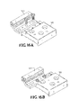
- FIG. 16A is an exploded perspective view of the combined clamp base as shown in FIG. 12 and the cable clamp as shown in FIG. 15 in a first position.
- FIG. 16B is a perspective view of the combined clamp base and cable clamp as shown in FIG. 16A .
- FIG. 16C is an exploded perspective view of the combined clamp base and cable clamp as shown in FIG. 16A in a second position.
- FIG. 16D is a perspective view of the combined clamp base and the cable clamp as shown in FIG. 16A .
- FIG. 16E is an exploded perspective view of the combined clamp base as shown in FIG. 12 and the cable clamp as shown in FIG. 13 .
- FIG. 16F is a perspective view of the combined clamp base and cable clamp as shown in FIG. 16E .
- FIG. 16G is a side elevation view of the combined clamp base and cable clamp as shown in FIG. 16B .
- FIG. 16H is a top plan view of the combined clamp base and cable clamp as shown in FIG. 16B .
- FIG. 17 is a side perspective view of another embodiment of a telescoping door assembly in a first position showing four door panels and the bracket assembly as shown in FIG. 1 secured to top edges of three of the door panels.
- FIG. 18 is a top plan view of the embodiment of the telescoping door assembly as shown in FIG. 17 .
- FIG. 19A is a front perspective view of a third embodiment of a cable clamp for use in the door assembly as shown in FIG. 17 .
- FIG. 19B is a rear perspective view of the cable clamp as shown in FIG. 19A .
- FIG. 19C is a rear elevation view of the cable clamp as shown in FIG. 19A .
- FIG. 19D is a bottom plan view of the cable clamp as shown in FIG. 19A .
- FIG. 19E is a side elevation view of the cable clamp as shown in FIG. 19A .
- FIG. 19F is a close-up view of the cable clamp as shown in FIG. 19E .
- FIG. 20A is a front perspective view of a fourth embodiment of a cable clamp for use in the door assembly as shown in FIG. 17 .
- FIG. 20B is a rear perspective view of the cable clamp as shown in FIG. 20A .
- FIG. 20C is a bottom plan view of the cable clamp as shown in FIG. 20A .
- FIG. 20D is a front elevation view of the cable clamp as shown in FIG. 20A .
- FIG. 20E is a side elevation view of the cable clamp as shown in FIG. 20A .
- FIG. 20F is a close-up view of a first portion of the cable clamp as shown in FIG. 20E .
- FIG. 20G is a close-up view of a second portion of the cable clamp as shown in FIG. 20E .
- FIG. 21A is an exploded perspective view of a fifth embodiment of a cable clamp for use in the door assembly as shown in FIG. 17 .
- FIG. 21B is a perspective view of the cable clamp as shown in FIG. 21A .
- FIG. 21C is an end elevation view of the cable clamp as shown in FIG. 21A .
- FIG. 21D is a side elevation view of the cable clamp as shown in FIG. 21A with internal structure shown in phantom.
- FIG. 21E is a bottom plan view of the cable clamp as shown in FIG. 21A .
- FIG. 22 is a top plan view of the embodiment of the telescoping door assembly as shown in FIG. 17 in a second position.
- FIG. 23 is a partial outer perspective view of the embodiment of the telescoping door assembly as shown in FIG. 17 in a third position.
- FIG. 24 is an inner perspective view of the embodiment of the telescoping door assembly in the third position as shown in FIG. 23 with portions of the door panels cut away.
- FIG. 25 is a close-up top plan view of an inner end of a leading door panel and an outer end of a first middle door panel of the door assembly as shown in FIG. 23 .
- FIG. 26 is a close-up top perspective view of an inner end of a second middle door panel and an outer end of a trailing door panel of the door assembly as shown in FIG. 23 .
- FIG. 27A is a top perspective view of a spacer for use in connecting guide tracks as shown in FIG. 4 .
- FIG. 27B is a front perspective view of the spacer as shown in FIG. 27A .
- the door assembly 50 comprises three door panels 52 movable along an upper guide track 54 extending the length of an opening (not shown), and a bracket assembly 55 secured to the middle door panel 52 .
- the door panels 52 are depicted as having a length sufficient only to allow a full drawing of all component parts of the door assembly 50 .
- Each door panel 52 includes a top edge 56 , a bottom edge 58 , an outer edge 60 and an opposing inner edge 62 , and major side surfaces 64 .
- the door panels 52 can be formed from wood, a wood-polymer composite material, a polymer, glass, mirrors or any other material capable of forming a door panel or room divider.
- the upper guide track 54 is an elongated body having one or more downwardly opening longitudinal channels 66 formed therein.
- the guide track 54 is preferably formed from a suitable material having sufficient strength to withstand the weight of the door panels 52 without undergoing deformation.
- the guide track 54 is adapted to be mounted in parallel relation to the overhead structure (not shown) defining the door opening.
- the guide track 54 includes an elongated base wall 68 which is configured to be fixed to the overhead structure by any suitable means, for example, a series of longitudinally spaced fasteners, such as screws or the like.
- a plurality of laterally spaced walls 70 extend downwardly from the base wall 68 to form the channels 66 .
- Each channel 66 is defined by a pair of the walls 70 and the base wall 68 . Although three channels 66 are shown, it is understood two channels can be provided, or more than three channels can be provided depending upon the number of door panels.
- the terminal edges of each end wall includes an inwardly extending flange 72 .
- the flanges 72 are adapted to engage the wheels of roller assemblies on the door panels 52 .
- a J-shaped door guide 74 is provided for each door panel 52 to guide the bottom edges 58 of the door panels 52 during their sliding movement.
- the door guides 74 are secured to the door frame or to the door panel surface 64 adjacent to the lower outer edge 60 of the immediately adjacent door panel 52 .
- the bottom edges 58 of the door panels 52 define longitudinal grooves 76 for slidingly receiving the shorter leg of the door guides 74 and guiding linear movement of the door panels 52 .
- An endplate 78 is secured to the outer edge 60 and the inner edge 62 of the door panels 52 adjacent their bottom edge 58 .
- the endplates 78 close the ends of the longitudinal grooves 76 providing an endpoint for the relative sliding movement of the door panels 52 .
- a pair of roller assemblies 80 is mounted to the top edge 56 of each door panel 52 .
- Each roller assembly 80 includes a carriage assembly 82 , including wheels 83 configured to be movable horizontally along the guide track 54 .
- the roller assemblies 80 also include a support member 84 configured to be mounted to the top edge 56 of the door panels 52 .
- the carriage assembly 82 includes a vertically extending locking post 86 and the support member 84 defines an arcuate opening 88 for securely receiving the locking post 86 therein. Roller assemblies of this type are well known in the art.
- the pairs of roller assemblies 80 function to mount the door panels 52 for movement along the guide track 54 between the sides of the structure (not shown) defining the door opening.
- the channels 66 of the guide track 54 are sized to receive the roller assemblies 80 therein such that the wheels 83 of the roller assemblies 80 contact opposing inward flanges 72 of the walls 70 defining the channel 66 .
- FIG. 5 An embodiment of a bracket assembly 55 for use with the door assembly 50 is shown in FIG. 5 .
- the bracket assembly 55 comprises a monolithic bracket 90 , rotatable pulleys 92 at each end of the bracket 90 , and a cable 94 extending around the pulleys 92 .
- the bracket 90 comprises an elongated base member 96 sized and shaped to fit on the top edge 56 of a door panel 52 .
- the base member 96 includes a web 98 and two walls 100 depending from the longitudinal edges of the web.
- a plurality of holes are provided through the bracket 90 for receiving fasteners for securing the bracket to the top edge 56 of the middle door panel 52 .
- the bracket 90 is configured to extend beyond the inner edge 62 of the door panel 52 .
- the bracket 90 has an opening 102 at each end for receiving the pulley axles.
- a cable 104 is disposed in the circumferential grooves of the pulleys 92 .
- Each end of the cable 104 includes a loop 105 for receiving the opposite ends of a coil spring 106 .
- Two slots 108 are provided longitudinally inwardly from the pulley axle openings 102 for securely receiving a pair of carriage assemblies 82 .
- a stop 110 is secured at the outer end of the bracket 90 .
- the stop 110 comprises two brackets. Each bracket is secured to one of the walls 100 of the web 98 , each of the brackets having a flange extending upwardly transversely with respect to the bracket 90 .
- a T-shaped alignment guide 110 is secured between the bracket 90 and the inner top edge 56 of the door panel 52 .
- the alignment guide 110 defines a shallow pocket for receiving the trailing inner edge 62 of the door panel 52 . This arrangement ensures proper alignment of the bracket 90 with the associated door panel 52 .
- the base member 96 may also have alignment tabs for various size door panels and applications for ease of installation. The alignment tabs accommodate a range of door sizes from about 1.5 feet wide to about 6 feet wide.
- the bracket 90 may be formed from extruded aluminum, roll-formed aluminum, roll-formed steel or other materials that are capable of suitable for use as the bracket fitted onto the door panel 52 .
- An outer end stop 112 ( FIG. 8 ) is compression fitted into the end of each channel 66 .
- the end stops 112 conceal the open ends of the channels 66 and provide a hard stop for the carriage assemblies 82 .
- retaining clip stops 114 ( FIG. 9 ) are fitted into the open inner ends of the channels 66 for providing a hard stop for the carriage assemblies 82 at the inner end of the channels 66 .
- Each retaining clip stop 114 includes a resilient leg 116 extension sized for receiving a wheel.
- a backstop assembly 118 ( FIG. 10 ) is also provided in the pocket of the door frame for a cushioned stop of each door panel 52 of the door assembly 50 at its innermost position.
- the trailing door panel 52 includes a cable clamp base 120 secured by screws to the outer end of the top edge 56 of the door panel 52 .
- a first cable clamp 122 ( FIG. 12 ) is secured to the cable clamp base 120 .
- the first cable clamp 122 defines a circular opening 123 for receiving a pin secured to the cable 104 such that the trailing door panel 52 moves with the cable 104 .
- a second cable clamp 124 is shown secured to the cable clamp base 120 at the inner end of the top edge 56 of the leading door 52 .
- the second cable clamp 124 defines a groove 125 for receiving the cable 104 .
- a plurality set screws extending into the groove 125 fix the cable 104 to the second cable clamp 124 for securing the inner end of the leading door panel 52 to the cable 104 .
- the door panels 52 are aligned and contiguous in their innermost position, for example, in the pocket of a wall.
- the cable 104 will rotate around the pulleys 92 because the leading door panel 52 is secured to the cable 104 by the second cable clamp 124 .
- the middle door panel 52 will also advance at the same rate as the leading door.
- the position of the leading door panel relative to the middle door panel will change at the same rate as the relative position of the middle door 52 to the trailing door panel 52 .
- This arrangement provides for the telescoping effect to the outward movement of the door panels 52 .
- the sliding door assembly 50 described herein can be used as door system for a closet including but not limited to a walk-in closet and a divider for sub-dividing a room or space into more than one smaller spaces. It is contemplated that the sliding door assembly 50 can have varying heights and widths, which are dependent upon the size opening of the closet or the ceiling height of the space.
- FIGS. 16 and 17 Another embodiment of a telescoping door assembly is shown in FIGS. 16 and 17 and generally designated at 130 .
- the door assembly 130 comprises four door panels 52 movable along an upper guide track (not shown) extending the length of an opening.
- a bracket assembly 55 is secured to the top edge 56 of the two middle door panels 52 and the trailing door panel 52 .
- a second cable clamp 124 is secured to a cable clamp base 120 at the inner end of the top edge 56 of the leading door panel 52 and fixed to the cable 104 of the first middle door 52 .
- the first middle door panel 52 includes a cable clamp ( FIG. 18 ) secured by screws to the bracket 90 adjacent the inner edge 62 of the first middle door panel 52 .
- a plurality of set screws extend into the groove 133 to fix the third cable clamp 132 on the first middle door panel 52 to the cable 104 of the second middle door panel 52 for securing the inner end of the first middle door panel 52 to the cable 104 .
- the second middle door panel 52 includes a fourth cable clamp 134 ( FIG. 19 ) secured by screws to the bracket 90 adjacent the outer edge 60 of the second middle door panel 52 .
- the fourth cable clamp 134 defines a circular opening 135 for receiving a pin secured to the cable 104 of the first middle door panel 52 such that the second middle door 52 moves with the cable 104 of the first middle door 52 .
- the second middle door panel 52 includes a third cable clamp 132 secured by screws to the bracket 90 adjacent the inner edge 62 of the second middle door panel 52 .
- a plurality of set screws extend into the groove to fix the third cable clamp 132 on the inner end of the second middle door panel 52 to the cable 104 on the trailing door panel 52 .
- a fifth embodiment of a cable clamp 136 is shown.
- This cable clamp comprises four pieces, including two pieces 138 , 139 which together define a C-shaped aperture for slidingly receiving a portion of a channel 66 of the guide track 54 .
- the fifth embodiment of the cable clamp 136 is fixed to the channel 66 carrying the trailing door panel 52 .
- the fifth embodiment of the cable clamp 136 includes a clamp portion 140 defining an opening 141 for receiving a pin secured to the cable 104 on the trailing door panel 52 .
- the door panels 52 of this embodiment of the door assembly 130 are aligned and contiguous in their innermost position for example, in the pocket of a wall as shown in FIG. 17 .
- the cable 104 of the first middle door panel 52 will rotate with the linear outward movement of the leading door panel 52 because the leading door panel is secured to the cable 104 of the first middle door by the second cable clamp 124 .
- the first middle door panel 52 is fixed to the cable 104 of the second middle door panel 52
- the second middle door panel 52 is secured to the cable of trailing door panel 52 .
- the fifth embodiment of the cable clamp 136 fixes the cable 104 of the trailing door panel 52 to the guide track 54 .
- the first and second middle door panels and the trailing door panel also advance at the same rate as the leading door panel.
- the position of the leading door panel 52 relative to the first and second middle door panels 52 and the trailing door panel 52 will change at the same rate as the relative position of the leading door panel 52 to the first middle door panel.
- This arrangement provides for the telescoping effect to the outward movement of all of the door panels of the door assembly 130 .
- the trailing door panel 52 moves with the other door panels 52 and is not dragged outwardly. Returning the door panels to the first position in the pocket is in the reverse order.
- FIG. 26 illustrates the combination of a pair of guide tracks 54 held in a predetermined parallel relation by a track spacing member 150 .
- the spacing member 150 is configured to be mounted between the pair of guide tracks so as to retain the guide tracks in a predetermined parallel relationship.
- the bracket assembly 55 has many advantages, including combining at least two hangers and a multitude of other door hardware for sliding and telescoping doors into one bracket.
- the bracket establishes correct spacing on the top edge of a sliding and folding door.
- the bracket also provides correct spacing and fixtures for other door components, such as stops, soft close, telescoping hardware, and the like. Therefore, the new bracket drastically reduces installation time for sliding doorways and, particularly, when such doors incorporate telescoping and other special hardware.
- a nail and a screw may not be structural equivalents in that a nail employs a cylindrical surface to secure wooden parts together, whereas a screw employs a helical surface, in the environment of fastening wooden parts, a nail and a screw may be equivalent structures.
Landscapes
- Engineering & Computer Science (AREA)
- Mechanical Engineering (AREA)
- Wing Frames And Configurations (AREA)
Abstract
Description
Claims (4)
Priority Applications (1)
| Application Number | Priority Date | Filing Date | Title |
|---|---|---|---|
| US14/216,170 US9926735B2 (en) | 2013-03-15 | 2014-03-17 | Telescoping door integrated hardware |
Applications Claiming Priority (2)
| Application Number | Priority Date | Filing Date | Title |
|---|---|---|---|
| US201361793779P | 2013-03-15 | 2013-03-15 | |
| US14/216,170 US9926735B2 (en) | 2013-03-15 | 2014-03-17 | Telescoping door integrated hardware |
Publications (2)
| Publication Number | Publication Date |
|---|---|
| US20150020453A1 US20150020453A1 (en) | 2015-01-22 |
| US9926735B2 true US9926735B2 (en) | 2018-03-27 |
Family
ID=51862808
Family Applications (1)
| Application Number | Title | Priority Date | Filing Date |
|---|---|---|---|
| US14/216,170 Active US9926735B2 (en) | 2013-03-15 | 2014-03-17 | Telescoping door integrated hardware |
Country Status (2)
| Country | Link |
|---|---|
| US (1) | US9926735B2 (en) |
| CA (1) | CA2846841C (en) |
Cited By (3)
| Publication number | Priority date | Publication date | Assignee | Title |
|---|---|---|---|---|
| US20190024425A1 (en) * | 2014-10-03 | 2019-01-24 | Zdzislaw Stanislaw Wypych | Easy glide storm door |
| US20190194991A1 (en) * | 2016-09-15 | 2019-06-27 | Goldbrecht Inc. | Sliding door and window roller assembly |
| USD1057552S1 (en) * | 2020-09-15 | 2025-01-14 | Assa Abloy New Zealand Limited | Hanger for a folding panel system |
Families Citing this family (9)
| Publication number | Priority date | Publication date | Assignee | Title |
|---|---|---|---|---|
| JP6460401B2 (en) * | 2014-04-16 | 2019-01-30 | 株式会社北島製作所 | Interlocking sliding door opening and closing device and interlocking sliding door equipped with the same |
| DE102015005666B4 (en) * | 2015-05-02 | 2018-09-20 | Edgar Hakemann | Refrigerated display case, in particular door arrangement therefor |
| GB2553266A (en) * | 2016-06-26 | 2018-03-07 | James Monaghan Michael | Sliding assembly for doors |
| JP6530355B2 (en) * | 2016-08-05 | 2019-06-12 | 株式会社ムラコシ精工 | Opening and closing body interlocking device |
| WO2019152887A1 (en) | 2018-02-01 | 2019-08-08 | Oldcastle Building Envelope, Inc. | Demountable wall system and method |
| GB2586047B (en) * | 2019-07-31 | 2022-05-25 | Thermo Fisher Scient Bremen Gmbh | A sliding door assembly for an ICP torch box |
| USD1005826S1 (en) * | 2022-01-06 | 2023-11-28 | Renin Canada Corp. | Sliding door bracket |
| CN115059367B (en) * | 2022-07-15 | 2025-03-14 | 广东欧派克家居智能科技有限公司 | Hanging pulley and use method thereof |
| CN223106379U (en) * | 2023-11-27 | 2025-07-15 | 合肥美的电冰箱有限公司 | Sliding door mechanism, door assembly and refrigeration equipment |
Citations (21)
| Publication number | Priority date | Publication date | Assignee | Title |
|---|---|---|---|---|
| US1960860A (en) * | 1931-08-05 | 1934-05-29 | Allen Drew Company | Sliding door |
| GB877261A (en) | 1957-08-27 | 1961-09-13 | John Fossey Steel | Sliding glass door constructions |
| GB881202A (en) | 1959-05-04 | 1961-11-01 | Erwin Edward Spork | An improved sliding door roller mounting assembly |
| US3118170A (en) | 1961-10-19 | 1964-01-21 | Ekco Products Company | Sliding door hanger assembly |
| US3738013A (en) | 1970-08-20 | 1973-06-12 | Rockwell Mfg Co | Hinge butt template assembly |
| US3829929A (en) | 1971-05-07 | 1974-08-20 | Lawrence Brothers | Folding door hanger with emergency release |
| US4565031A (en) | 1983-02-02 | 1986-01-21 | Sugatsune Industrial Co., Ltd. | Rail arrangement for flush sliding door panels |
| EP0417000A1 (en) | 1989-09-07 | 1991-03-13 | Benjamin Azoulay | Suspended pocket door |
| US5884361A (en) * | 1994-10-06 | 1999-03-23 | Anthony's Manufacturing Company | Slider door mechanism, running gear mechanism and closure return |
| US6058665A (en) | 1998-03-10 | 2000-05-09 | Steelcase Development Inc. | Adjustable door and doorway construction |
| DE19952264A1 (en) * | 1998-10-29 | 2000-06-08 | Geze Gmbh | Modular system for door or window drive mechanisms |
| US6209171B1 (en) | 1999-10-01 | 2001-04-03 | The Stanley Works | Movable door mounting assembly |
| US6289643B1 (en) | 1999-09-07 | 2001-09-18 | Autoglide, Inc. | Residential motorized sliding door assembly |
| US6352097B1 (en) * | 1999-09-10 | 2002-03-05 | Rite-Hite Holding Corporation | Multi-panel door with an auxiliary drive mechanism |
| US6698138B1 (en) | 2003-04-09 | 2004-03-02 | Heade Technology Co., Ltd. | Adjustable pulley assembly for a suspended door |
| US6983512B2 (en) | 2002-07-23 | 2006-01-10 | Masco Corporation | Movable door mounting assembly with trolley locking structure |
| US7021007B2 (en) | 2003-07-03 | 2006-04-04 | Home Decor Holding Company | Double-sided sliding door assembly |
| US7117559B1 (en) | 2004-08-14 | 2006-10-10 | David Barber | Support system for pocket doors |
| US8226130B2 (en) | 2005-12-09 | 2012-07-24 | Industrilås i NässjöAB | Control roller mechanism-activator |
| KR101182413B1 (en) * | 2011-09-14 | 2012-09-13 | 안재옥 | Three sliding door |
| EP2706181A2 (en) * | 2012-09-10 | 2014-03-12 | Sunparadise Establishment | Actuation device for moving a slidable closing element |
-
2014
- 2014-03-17 CA CA2846841A patent/CA2846841C/en active Active
- 2014-03-17 US US14/216,170 patent/US9926735B2/en active Active
Patent Citations (21)
| Publication number | Priority date | Publication date | Assignee | Title |
|---|---|---|---|---|
| US1960860A (en) * | 1931-08-05 | 1934-05-29 | Allen Drew Company | Sliding door |
| GB877261A (en) | 1957-08-27 | 1961-09-13 | John Fossey Steel | Sliding glass door constructions |
| GB881202A (en) | 1959-05-04 | 1961-11-01 | Erwin Edward Spork | An improved sliding door roller mounting assembly |
| US3118170A (en) | 1961-10-19 | 1964-01-21 | Ekco Products Company | Sliding door hanger assembly |
| US3738013A (en) | 1970-08-20 | 1973-06-12 | Rockwell Mfg Co | Hinge butt template assembly |
| US3829929A (en) | 1971-05-07 | 1974-08-20 | Lawrence Brothers | Folding door hanger with emergency release |
| US4565031A (en) | 1983-02-02 | 1986-01-21 | Sugatsune Industrial Co., Ltd. | Rail arrangement for flush sliding door panels |
| EP0417000A1 (en) | 1989-09-07 | 1991-03-13 | Benjamin Azoulay | Suspended pocket door |
| US5884361A (en) * | 1994-10-06 | 1999-03-23 | Anthony's Manufacturing Company | Slider door mechanism, running gear mechanism and closure return |
| US6058665A (en) | 1998-03-10 | 2000-05-09 | Steelcase Development Inc. | Adjustable door and doorway construction |
| DE19952264A1 (en) * | 1998-10-29 | 2000-06-08 | Geze Gmbh | Modular system for door or window drive mechanisms |
| US6289643B1 (en) | 1999-09-07 | 2001-09-18 | Autoglide, Inc. | Residential motorized sliding door assembly |
| US6352097B1 (en) * | 1999-09-10 | 2002-03-05 | Rite-Hite Holding Corporation | Multi-panel door with an auxiliary drive mechanism |
| US6209171B1 (en) | 1999-10-01 | 2001-04-03 | The Stanley Works | Movable door mounting assembly |
| US6983512B2 (en) | 2002-07-23 | 2006-01-10 | Masco Corporation | Movable door mounting assembly with trolley locking structure |
| US6698138B1 (en) | 2003-04-09 | 2004-03-02 | Heade Technology Co., Ltd. | Adjustable pulley assembly for a suspended door |
| US7021007B2 (en) | 2003-07-03 | 2006-04-04 | Home Decor Holding Company | Double-sided sliding door assembly |
| US7117559B1 (en) | 2004-08-14 | 2006-10-10 | David Barber | Support system for pocket doors |
| US8226130B2 (en) | 2005-12-09 | 2012-07-24 | Industrilås i NässjöAB | Control roller mechanism-activator |
| KR101182413B1 (en) * | 2011-09-14 | 2012-09-13 | 안재옥 | Three sliding door |
| EP2706181A2 (en) * | 2012-09-10 | 2014-03-12 | Sunparadise Establishment | Actuation device for moving a slidable closing element |
Non-Patent Citations (2)
| Title |
|---|
| Rothley Ltd, Sliding Door Gear-Herkules120 Sliding Door System-Kit for 1 door, Jan. 13, 2014, http://www.rothley.com/trade/product-details.asp?PID=1392&GPN=HERK120& . . . . |
| Rothley Ltd, Sliding Door Gear—Herkules120 Sliding Door System—Kit for 1 door, Jan. 13, 2014, http://www.rothley.com/trade/product-details.asp?PID=1392&GPN=HERK120& . . . . |
Cited By (5)
| Publication number | Priority date | Publication date | Assignee | Title |
|---|---|---|---|---|
| US20190024425A1 (en) * | 2014-10-03 | 2019-01-24 | Zdzislaw Stanislaw Wypych | Easy glide storm door |
| US10641024B2 (en) * | 2014-10-03 | 2020-05-05 | Zdzislaw Stanislaw Wypych | Easy glide storm door |
| US20190194991A1 (en) * | 2016-09-15 | 2019-06-27 | Goldbrecht Inc. | Sliding door and window roller assembly |
| US10808441B2 (en) * | 2016-09-15 | 2020-10-20 | Goldbrecht Inc. | Sliding door and window roller assembly |
| USD1057552S1 (en) * | 2020-09-15 | 2025-01-14 | Assa Abloy New Zealand Limited | Hanger for a folding panel system |
Also Published As
| Publication number | Publication date |
|---|---|
| CA2846841A1 (en) | 2014-09-15 |
| US20150020453A1 (en) | 2015-01-22 |
| CA2846841C (en) | 2021-02-16 |
Similar Documents
| Publication | Publication Date | Title |
|---|---|---|
| US9926735B2 (en) | Telescoping door integrated hardware | |
| US9091106B2 (en) | Panel hardware system and associated methods | |
| US20170298669A1 (en) | Sliding barn door hardware | |
| US8316914B2 (en) | Movable partitions, header assemblies for movable partitions, and methods of forming header assemblies for movable partitions | |
| US7174944B1 (en) | Triple slide assembly for sliding doors | |
| US8402699B2 (en) | Sliding privacy door for partition systems | |
| US8240354B2 (en) | Movable partition systems and components thereof including chain guide structures, and methods of forming and installing same | |
| US4821375A (en) | Recessing hinge mechanism | |
| US20090272707A1 (en) | Pocket door system | |
| US10508441B2 (en) | Demountable wall system | |
| KR20080035502A (en) | Apparatus and parts thereof, with feeders for supporting panels | |
| US9447579B2 (en) | Sliding door and pivoting door for demountable wall system | |
| CA2823357A1 (en) | Adjustable pocket door frame | |
| US20160340952A1 (en) | Sliding door with magnetic support | |
| KR20190046771A (en) | A sliding wall device having a cover member | |
| US20100218906A1 (en) | Modular Shade System | |
| US20050273976A1 (en) | Adjustable roller bracket device for retractable door hinge | |
| WO2006025582A1 (en) | Screen device | |
| EP3564473B1 (en) | Perimeter frame for glass doors | |
| KR101331393B1 (en) | Upper frame device for slide door of a built-in closet | |
| US20180213931A1 (en) | Vertically retractable counterweighted rack for overhead closet storage | |
| CA2360142A1 (en) | Partition frame structure | |
| CN119855971A (en) | Improvement of storage door suspension system | |
| CA3015101C (en) | Panel door system | |
| AU2016262687A1 (en) | Improved sliding door soft close system |
Legal Events
| Date | Code | Title | Description |
|---|---|---|---|
| AS | Assignment |
Owner name: PEMKO MANUFACTURING COMPANY, INC., CALIFORNIA Free format text: ASSIGNMENT OF ASSIGNORS INTEREST;ASSIGNOR:SPECK, RICHARD ADAM;REEL/FRAME:044329/0228 Effective date: 20151217 Owner name: PEMKO MANUFACTURING CO., TENNESSEE Free format text: ASSIGNMENT OF ASSIGNORS INTEREST;ASSIGNORS:GOOSSENS, PHILIP ANTHONY;SMALLS, DAMOND MAURICE;KARL, JEFFREY G.;SIGNING DATES FROM 20171106 TO 20171207;REEL/FRAME:044328/0982 |
|
| STCF | Information on status: patent grant |
Free format text: PATENTED CASE |
|
| AS | Assignment |
Owner name: ASSA ABLOY ACCESSORIES AND DOOR CONTROLS GROUP, INC., NORTH CAROLINA Free format text: CHANGE OF NAME;ASSIGNOR:YALE SECURITY INC.;REEL/FRAME:047790/0312 Effective date: 20171215 Owner name: YALE SECURITY INC., NORTH CAROLINA Free format text: MERGER;ASSIGNOR:PEMKO MANUFACTURING CO.;REEL/FRAME:047751/0649 Effective date: 20171215 Owner name: ASSA ABLOY ACCESSORIES AND DOOR CONTROLS GROUP, IN Free format text: CHANGE OF NAME;ASSIGNOR:YALE SECURITY INC.;REEL/FRAME:047790/0312 Effective date: 20171215 |
|
| CC | Certificate of correction | ||
| MAFP | Maintenance fee payment |
Free format text: PAYMENT OF MAINTENANCE FEE, 4TH YEAR, LARGE ENTITY (ORIGINAL EVENT CODE: M1551); ENTITY STATUS OF PATENT OWNER: LARGE ENTITY Year of fee payment: 4 |
|
| MAFP | Maintenance fee payment |
Free format text: PAYMENT OF MAINTENANCE FEE, 8TH YEAR, LARGE ENTITY (ORIGINAL EVENT CODE: M1552); ENTITY STATUS OF PATENT OWNER: LARGE ENTITY Year of fee payment: 8 |