EP2706181A2 - Actuation device for moving a slidable closing element - Google Patents
Actuation device for moving a slidable closing element Download PDFInfo
- Publication number
- EP2706181A2 EP2706181A2 EP13183367.5A EP13183367A EP2706181A2 EP 2706181 A2 EP2706181 A2 EP 2706181A2 EP 13183367 A EP13183367 A EP 13183367A EP 2706181 A2 EP2706181 A2 EP 2706181A2
- Authority
- EP
- European Patent Office
- Prior art keywords
- cylinder
- piston assembly
- slidable
- actuation device
- carrier member
- Prior art date
- Legal status (The legal status is an assumption and is not a legal conclusion. Google has not performed a legal analysis and makes no representation as to the accuracy of the status listed.)
- Withdrawn
Links
Images


Classifications
-
- E—FIXED CONSTRUCTIONS
- E05—LOCKS; KEYS; WINDOW OR DOOR FITTINGS; SAFES
- E05F—DEVICES FOR MOVING WINGS INTO OPEN OR CLOSED POSITION; CHECKS FOR WINGS; WING FITTINGS NOT OTHERWISE PROVIDED FOR, CONCERNED WITH THE FUNCTIONING OF THE WING
- E05F3/00—Closers or openers with braking devices, e.g. checks; Construction of pneumatic or liquid braking devices
- E05F3/02—Closers or openers with braking devices, e.g. checks; Construction of pneumatic or liquid braking devices with pneumatic piston brakes
-
- E—FIXED CONSTRUCTIONS
- E05—LOCKS; KEYS; WINDOW OR DOOR FITTINGS; SAFES
- E05F—DEVICES FOR MOVING WINGS INTO OPEN OR CLOSED POSITION; CHECKS FOR WINGS; WING FITTINGS NOT OTHERWISE PROVIDED FOR, CONCERNED WITH THE FUNCTIONING OF THE WING
- E05F5/00—Braking devices, e.g. checks; Stops; Buffers
- E05F5/003—Braking devices, e.g. checks; Stops; Buffers for sliding wings
-
- E—FIXED CONSTRUCTIONS
- E05—LOCKS; KEYS; WINDOW OR DOOR FITTINGS; SAFES
- E05F—DEVICES FOR MOVING WINGS INTO OPEN OR CLOSED POSITION; CHECKS FOR WINGS; WING FITTINGS NOT OTHERWISE PROVIDED FOR, CONCERNED WITH THE FUNCTIONING OF THE WING
- E05F1/00—Closers or openers for wings, not otherwise provided for in this subclass
- E05F1/08—Closers or openers for wings, not otherwise provided for in this subclass spring-actuated, e.g. for horizontally sliding wings
- E05F1/16—Closers or openers for wings, not otherwise provided for in this subclass spring-actuated, e.g. for horizontally sliding wings for sliding wings
-
- E—FIXED CONSTRUCTIONS
- E05—LOCKS; KEYS; WINDOW OR DOOR FITTINGS; SAFES
- E05Y—INDEXING SCHEME RELATING TO HINGES OR OTHER SUSPENSION DEVICES FOR DOORS, WINDOWS OR WINGS AND DEVICES FOR MOVING WINGS INTO OPEN OR CLOSED POSITION, CHECKS FOR WINGS AND WING FITTINGS NOT OTHERWISE PROVIDED FOR, CONCERNED WITH THE FUNCTIONING OF THE WING
- E05Y2201/00—Constructional elements; Accessories therefore
- E05Y2201/40—Motors; Magnets; Springs; Weights; Accessories therefore
- E05Y2201/47—Springs; Spring tensioners
- E05Y2201/482—Ribbon springs
-
- E—FIXED CONSTRUCTIONS
- E05—LOCKS; KEYS; WINDOW OR DOOR FITTINGS; SAFES
- E05Y—INDEXING SCHEME RELATING TO HINGES OR OTHER SUSPENSION DEVICES FOR DOORS, WINDOWS OR WINGS AND DEVICES FOR MOVING WINGS INTO OPEN OR CLOSED POSITION, CHECKS FOR WINGS AND WING FITTINGS NOT OTHERWISE PROVIDED FOR, CONCERNED WITH THE FUNCTIONING OF THE WING
- E05Y2201/00—Constructional elements; Accessories therefore
- E05Y2201/60—Suspension or transmission members; Accessories therefore
- E05Y2201/622—Suspension or transmission members elements
- E05Y2201/644—Flexible elongated pulling elements; Members cooperating with flexible elongated pulling elements
- E05Y2201/646—Flexible elongated pulling elements; Members cooperating with flexible elongated pulling elements continuous, e.g. closed loops
-
- E—FIXED CONSTRUCTIONS
- E05—LOCKS; KEYS; WINDOW OR DOOR FITTINGS; SAFES
- E05Y—INDEXING SCHEME RELATING TO HINGES OR OTHER SUSPENSION DEVICES FOR DOORS, WINDOWS OR WINGS AND DEVICES FOR MOVING WINGS INTO OPEN OR CLOSED POSITION, CHECKS FOR WINGS AND WING FITTINGS NOT OTHERWISE PROVIDED FOR, CONCERNED WITH THE FUNCTIONING OF THE WING
- E05Y2201/00—Constructional elements; Accessories therefore
- E05Y2201/60—Suspension or transmission members; Accessories therefore
- E05Y2201/622—Suspension or transmission members elements
- E05Y2201/644—Flexible elongated pulling elements; Members cooperating with flexible elongated pulling elements
- E05Y2201/654—Cables
Definitions
- the present invention relates to an actuation device for moving a slidable closing element between a closed position and an open position, the slidable closing element being a sliding window, a sliding door or the like, the actuation device including a slidable carrier member for engaging the slidable closing element, the slidable carrier member being biased for sliding movement by means of a spring element, and the movement of the slidable carrier member being damped by means of a piston assembly arranged displaceably in a cylinder between a first end of the cylinder and a second end of the cylinder in such a way that a difference in gas pressure may be created between a first side of the piston assembly and a second side of the piston assembly.
- EP 0 589 822 B1 discloses an opening device for a sliding window or door.
- the opening device includes a slider arranged slidably along the inside of a guide rail having a rectangular cross-section.
- the slider is provided with two so-called constant force springs having free ends fixed to a first end of the guide rail, thereby urging the slider in the direction of said first end of the guide rail.
- the slider is provided with a drive member extending out through a longitudinally extending slot provided in a wall of the guide rail so that the drive member may engage an edge of the window or door to be opened.
- the opening device furthermore includes a dampening cylinder arranged at an end of the guide rail.
- a piston arranged in the dampening cylinder is connected to the slider by means of a piston rod in order to dampen the movement of the slider.
- a shorter device may be required.
- US 4,004,372 discloses a coil spring type closer for sliding doors which is adapted to cushion and retard the final stages of the closing movement of the door by means of a dampening cylinder arranged on a door frame.
- this closing arrangement is only able to dampen the final stages of the closing movement which may be insufficient in the case of large doors or windows or in the case of a number of successively arranged slidable elements adapted to be opened or closed sequentially by means of the device.
- the device requires an installation length that is substantially longer than the stroke of sliding element to be opened or closed.
- the object of the present invention is to provide an actuation device of the above-mentioned type that is more compact.
- the spring element is arranged to extend inside the cylinder between the first or second end of the cylinder and the piston assembly, a first guide roller is arranged at the first end of the cylinder and a second guide roller is arranged at the second end of the cylinder, a first wire section extends inside the cylinder from the piston assembly, around the first guide roller, outside the cylinder to the slidable carrier member, and a second wire section extends outside the cylinder from the slidable carrier member, around the second guide roller, and inside the cylinder to the piston assembly, so that the slidable carrier member is displaceable together with the piston assembly.
- the combined effect of arranging the spring element to extend inside the cylinder and arranging wire sections guided around guide rollers for displacing the slidable carrier member together with the piston assembly may provide an actuation device that is much more compact than known devices.
- the spring element is adapted to bias the piston assembly towards a position at the second end of the cylinder
- the first end of the cylinder is provided with a first end plug
- the first end plug has a hole through which the first wire section extends
- the difference between the outer diameter of the first wire section and the diameter of the hole is small enough in order to create a pressure reduction inside the cylinder between the first end plug and the piston assembly when the piston assembly travels in the direction against the second end of the cylinder.
- the piston assembly or the first end plug is provided with a check valve allowing air to flow through the check valve out from the space in the cylinder between the first end plug and the piston assembly when the piston assembly travels in the direction against the first end of the cylinder, but preventing air from flowing through the check valve into the space in the cylinder between the first end plug and the piston assembly when the piston assembly travels in the direction against the second end of the cylinder.
- the dampening effect may be obtained as the biased spring element is released to displace the slidable closing element in the direction against the second end of the cylinder, but the dampening effect may be avoided when the slidable closing element is returned in the direction against the first end of the cylinder. It may therefore be easier to return the slidable closing element, which may for instance be done manually.
- the spring element is formed by one or more so-called constant force springs
- each constant force spring includes a strip coiled on a drum, and the strip exerts an at least substantially constant restraining force to resist uncoiling.
- the necessary force may be adapted to individual requirements by including a suitable number of constant force springs.
- the drum is mounted on the piston assembly and the strip has a free end fixed to the cylinder at its second end.
- the rolled-out part of the strip will not translate in relation to the cylinder as the piston assembly is displaced, and thereby sliding resistance and resulting wear may be prevented. Possible wear of the inside of the cylinder wall could result in that the piston assembly would not seal properly against the cylinder wall.
- the piston assembly includes a first piston part connected to a second piston part by means of two spaced apart plates, the drum of the one or more so-called constant force springs is fixed between the two spaced apart plates, and at least the first piston part includes a cylindrical section sealed against the cylinder.
- the first and second piston parts may thereby be spaced apart and therefore provide good guidance of the entire piston assembly in the cylinder so that it may be avoided that forces resulting from the constant force spring or springs may skew the piston assembly in the cylinder.
- the second piston part is adapted to be guided along the inside of the cylinder and includes a recess, said recess being so formed and so arranged that the rolled-out part of the strips of the so-called constant force springs may extend through the recess when the piston assembly is displaced in the cylinder.
- the strips may extend through a recess in the second piston part that does not necessarily need to be sealed but may be guided in order to steer the piston assembly in the cylinder. Thereby, a sealing mechanism between the strips and the piston assembly may be avoided.
- the recess of the second piston part is formed in the periphery of the second piston part.
- an even more compact actuation device may be provided, as the diameter of the cylinder may be so small that the rolled-up strips on their drums may just fit inside the cylinder.
- friction between the strips and the second piston part may be minimized, as practically only an inner side of the innermost strip in the cylinder may slide against the recess of the second piston part; the outer side of the strips may at least substantially not translate in relation to the inside of the cylinder and therefore not contribute with any friction.
- a first end plug has a recess in which the first guide roller is arranged partly extending from the recess
- a second end plug has a recess in which the second guide roller is arranged partly extending from the recess.
- each one of the first end plug and the second end plug is adjustably connected to a respective mounting bracket for the device, so that the first and second end plugs are rotatably adjustable in relation to the mounting bracket about a central axis of the cylinder.
- the exact position of the part of the first and second wire sections extending outside the cylinder may be adapted to the desired position of the slidable carrier member according to tolerances and according to possible different configurations of a slidable closing element to be actuated.
- the slidable carrier member is arranged to travel at least substantially in parallel with the travel direction of the piston assembly.
- the axis of the cylinder of the actuation device may be arranged at least substantially in parallel with a slidable closing element to be actuated, and the slidable carrier member may easily be directly mounted on said slidable closing element.
- the first or the second wire section is attached to the slidable carrier member via a tension spring. Thereby, it may be ensured that the first and second wire sections are maintained suitably tensioned.
- the first or the second wire section is attached to the slidable carrier member by means of an adjustment mechanism allowing adjustment of the tension of the wire section, for instance by rotation of a screw.
- the first and second wire sections may be manually tensioned upon installation of the actuation device or subsequently in the case that the wire sections should become too loose during operation.
- the present invention further relates to a balcony closing arrangement including a number of successively arranged slidable window elements adapted to close a balcony and an actuation device as described above arranged to move the slidable window elements to open position upon actuation, wherein the slidable carrier member is adapted to engage a first slidable window element, wherein a second and possibly further slidable window elements each are provided with a protrusion for engagement with a neighbouring slidable window element, so that when the first slidable window element is moved from a first end of the balcony closing arrangement in an opening direction, the second and possibly further slidable window elements may subsequently be moved in the opening direction one after each other so that, finally, all slidable window elements will be positioned substantially behind each other at a second end of the balcony closing arrangement, and wherein the first slidable window element is provided with a coupling part adapted to engage an automatic release mechanism arranged at the first end of the balcony closing arrangement so that activation of the automatic release mechanism may
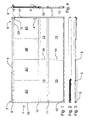
- Fig. 1 shows a balcony closing arrangement 1 including four successively arranged slidable window elements 2A, 2B, 2C, 2D adapted to close a balcony in the position shown in Figs. 1 and 3 .
- a first slidable window element 2A which in the closed position is positioned at a first end 6 of the balcony closing arrangement, at the right side in the figure, is automatically displaceable in the left direction by means of an actuation device 3 according to the present invention arranged along an upper edge of the balcony closing arrangement 1 or is manually displaceable by means of a handle 4.
- the second, third and fourth slidable window elements 2B, 2C, 2D are each provided with a protrusion 5 for engagement with a left edge of a neighbouring slidable window element 2A, 2B, 2C, respectively, so that when the first slidable window element 2A is moved from the first end 6 of the balcony closing arrangement 1 in an opening direction, the second, third and fourth slidable window elements 2B, 2C, 2D may subsequently be moved in the opening direction one after each other so that, finally, all slidable window elements 2A, 2B, 2C, 2D are positioned substantially behind each other at a second end 7 of the balcony closing arrangement 1, as shown in Fig. 2 .
- the protrusions 5 may furthermore be used as a handle for manually returning the second, third and fourth slidable window elements 2B, 2C, 2D to the initial position shown in Figs. 1 and 3 or for manually opening one of these elements by displacement in the left or right direction from the closed position show in
- Figs. 1 and 3 upon displacement of the first slidable window element 2A, the other slidable window elements 2B, 2C, 2D may be in any possible position to which they have been previously moved manually. Regardless of the initial position of each of the other slidable window elements 2B, 2C, 2D, the position of the elements after automatic opening by the actuation device 3 will be as illustrated in Fig. 2 , whereby all slidable window elements 2A, 2B, 2C, 2D are positioned substantially behind each other at a second end 7 of the balcony closing arrangement 1.
- each of the slidable window elements 2A, 2B, 2C, 2D is slidable in a separate corresponding track 8A, 8B, 8C, 8D in an upper horizontal balcony profile 9, as illustrated in Fig. 9 .
- the lower edge of each of the slidable window elements 2A, 2B, 2C, 2D is slidably mounted on a lower horizontal profile 10 in a well-known manner by means of not shown rollers.
- panel type filling elements 13 are arranged, further separated by an intermediate vertical profile 14.
- filling elements may be arranged in any suitable way or they may be unnecessary, depending on the balcony to be covered.
- the actuation device 3 is adapted to constantly bias the first slidable window element 2A in the opening direction, that is to the left in Fig. 1 , when the first slidable window element 2A is positioned at the first end 6 of the balcony closing arrangement, as discussed in further detail below. Therefore, the first slidable window element 2A is provided with a coupling part 15 adapted to engage an automatic release mechanism 16 arranged at the first end 6 of the balcony closing arrangement on a vertical profile 17 so that activation of the automatic release mechanism 16 may release the coupling part 15, whereupon the actuation device 3 may move the slidable window elements from the first to the second end of the balcony closing arrangement.
- the automatic release mechanism 16 has the form of an electromagnetic coil adapted to attract an anchor plate 19 of the coupling part 15. Thereby, the opening of the balcony closing arrangement may be initiated electrically, for instance by means of a fire alarm, smoke detector or the like.
- the automatic release mechanism 16 and the coupling part 15 may have any other suitable configuration depending on requirements.
- the coupling part 15 is further provided with a roller 20 adapted to roll on an edge of the upper horizontal balcony profile 9; thereby it may be ensured that the first slidable window element 2A does not skew when it is pulled manually by the handle 4 or by the actuation device 3.
- the roller 20 is mounted in a recess of a bracket 21 that is mounted to the first slidable window element 2A by means of screws 22; however, the roller 20 may also be mounted on the first slidable window element 2A by means of an element separate from the coupling part 15 in any suitable way.
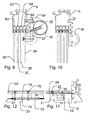
- the actuation device 3 is shown in cross-section in Figs. 5 and 6 , seen sideways and from the top, respectively.
- the actuation device 3 is adapted for moving a slidable closing element between a closed position and an open position.
- the slidable closing element may be a sliding window, a sliding door or the like.
- it is illustrated how the actuation device 3 may be employed for the automatic opening of a balcony closing arrangement 1 including a number of successively arranged slidable window elements 2A, 2B, 2C, 2D as described above.
- the actuation device 3 includes a slidable carrier member 23 for engaging the slidable closing element which in the embodiments illustrated has the form of the first slidable window element 2A of the balcony closing arrangement 1.
- the slidable carrier member 23 is biased for sliding movement by means of a spring element 24, and the movement of the slidable carrier member 23 is damped by means of a piston assembly 25 arranged displaceably in a cylinder 26 between a first end 27 of the cylinder and a second end 28 of the cylinder in such a way that a difference in gas pressure may be created between a first side 29 of the piston assembly and a second side 30 of the piston assembly.
- the spring element 24 is formed by one or more so-called constant force springs 35A, 35B and is arranged to extend inside the cylinder 26 between the second end 28 of the cylinder 26 and the piston assembly 25.
- Each constant force spring 35A, 35B includes a strip 36A, 36B coiled on a respective drum 37A, 37B, wherein the strip exerts an at least substantially constant restraining force to resist uncoiling.
- the drum 37A, 37B is mounted on the piston assembly 25 and the strips 36A, 36B each has a free end fixed to the cylinder at its second end 28.
- spring element 24 has been illustrated in a preferred form including one or more so-called constant force springs, it may have any suitable form, such as for instance a conventional compression spring arranged to extend inside the cylinder 26 between the first end 27 of the cylinder 26 and the piston assembly 25, or for instance a conventional tension spring arranged to extend inside the cylinder 26 between the second end 28 of the cylinder 26 and the piston assembly 25.
- a compression spring could also be arranged to extend inside the cylinder 26 between the second end 28 of the cylinder 26 and the piston assembly 25 in the case that the actuation device 3 should be adapted to bias the first slidable window element 2A in the closing direction instead of in the opening direction or in the case that the actuation device 3 should be arranged with the first and second ends 27, 28 of the cylinder reversed in relation to the embodiment described with relation to the figures.
- a first guide roller 31 is arranged at the first end 27 of the cylinder and a second guide roller 32 is arranged at the second end 28 of the cylinder.
- a first wire section 33 extends inside the cylinder 26 from the piston assembly 25, around the first guide roller 31, outside the cylinder to the slidable carrier member 23, and a second wire section 34 extends outside the cylinder from the slidable carrier member 23, around the second guide roller 32, and inside the cylinder to the piston assembly 25, so that the slidable carrier member 23 is displaceable together with the piston assembly 25.
- the first end 27 of the cylinder 26 is provided with a first end plug 38, and the second end 28 of the cylinder 26 is provided with a second end plug 39.
- the first end plug 38 has a hole 40 through which the first wire section 33 extends
- the second end plug 39 has a hole 41 through which the second wire section 34 extends.
- the holes 40, 41 are provided in respective bushings 42, 43 fixed in borings 44, 45 of the end plugs 38, 39 by means of screws 46, 47.
- the spring element is adapted to bias the piston assembly towards a position at the second end 28 of the cylinder 26
- the difference between the outer diameter of the first wire section 33 and the diameter of the hole 40 in the bushing 42 of the first end plug 38 is small enough in order to create a pressure reduction inside the cylinder 26 between the first end plug 38 and the piston assembly 25 when the piston assembly travels in the direction against the second end 28 of the cylinder.
- the creation of this pressure reduction may result in that a more or less constant velocity of the sliding opening or closing action may be obtained.
- the difference between the outer diameter of the second wire section 34 and the diameter of the hole 41 in the bushing 43 of the second end plug 39 is small enough in order to create an overpressure in the cylinder 26 between the second end plug 39 and the piston assembly 25 when the piston assembly travels in the direction against the second end 28 of the cylinder.
- the dampening of the build up overpressure will, however, build up during the stroke of the piston assembly and therefore be most efficient at the last part of the stroke.
- the first end plug 38 may preferably be sealed against the cylinder by means of an O-ring 48 as shown in Fig. 17 .
- the actuation device 3 may also be dampened only by means of the creation of an overpressure as described above.
- the difference between the outer diameter of the first wire section 33 and the diameter of the hole 40 in the bushing 42 of the first end plug 38 is small enough in order to create a pressure reduction inside the cylinder 26.
- the first end plug 38 or even the cylinder 26 may be provided with an adjustable valve allowing an additional amount of air to enter the cylinder during displacement. The opening of this valve may then modify the pressure reduction created.
- the piston assembly 25 is provided with a check valve 49 allowing air to flow through the check valve out from the space in the cylinder 26 between the first end plug 38 and the piston assembly 25 when the piston assembly travels in the direction against the first end 27 of the cylinder 26, but preventing air from flowing through the check valve 49 into the space in the cylinder between the first end plug and the piston assembly when the piston assembly travels in the direction against the second end 28 of the cylinder.
- the check valve 49 may of course just as well be arranged in the first end plug 38 or possibly in the cylinder 26. As illustrated in Figs.
- the check valve 49 includes a valve element 50 adapted to be biased against a valve seat 51 by means of a spring 52.
- the valve seat 51 is formed in a bore 53 in a first piston part 54 of the piston assembly 25.
- the spring 52 is fixed in the bore 53 by means of a screw or pin 58 inserted into a bore 59 in the first piston part 54 at right angles to the bore 53.
- the check valve 49 may be of any suitable kind known in the art.
- the piston assembly 25 includes the first piston part 54 connected to a second piston 55 part by means of two spaced apart parallel plates 56, 57 mounted to the first and second piston parts 54, 55 by means of screws 60.
- the drums 37A, 37B of the two so-called constant force springs 35A, 35B are fixed between the two spaced apart parallel plates, and the first piston part 54 includes a cylindrical section 61 sealed against the cylinder 26 by means of an O-ring 62 arranged in a peripheral groove 63 of the cylindrical section 61.
- two spaced apart parallel plates 56, 57 has sufficient length in order to provide space for a third constant force springs, should this be necessary.
- any number of constant force springs may be possible according to requirements.
- the second piston part 55 is adapted to be guided along the inside of the cylinder 26 by means of small plastic plugs 64 inserted into the periphery of the second piston part 55. Furthermore, the second piston part 55 includes a recess 65 formed in its periphery and being so formed and so arranged that the rolled-out part of the strips 36A, 36B of the so-called constant force springs 35A, 35B may extend through the recess 65 when the piston assembly 25 is displaced in the cylinder 26.
- the first end plug 38 has a recess 66 in which the first guide roller 31 is arranged partly extending from the recess 66
- the second end plug 39 has a recess 67 in which the second guide roller 32 is arranged partly extending from the recess 67.
- either end 27, 28 of the cylinder 26 are provided with a slot not visible in the figures, through which the first and second guide rollers 31, 32, respectively, may protrude.
- the end the first and second end plugs 38, 39 may protrude a certain distance out from the respective end of the cylinder so that said slots are not necessary.
- the first guide roller 31 and the second guide roller 32 may, of course, be arranged at either end of the cylinder 26 in any other suitable way than by means of the end plugs 38, 39 as illustrated, for instance by means of suitable brackets.
- the second end plug 39 has a flat face 72 to which the free end of the strips 36A, 36B of the constant force spring 35A, 35B are mounted by means of a screw so that they are fixed to the cylinder at its second end 28 as mentioned above.
- each one of the first end plug 38 and the second end plug 39 is adjustably connected to a respective mounting bracket 68, 69 for the device by means of a respective screw 70, 71, so that the first and second end plugs are rotatably adjustable in relation to the mounting bracket about a central axis of the cylinder.
- Fig. 9 illustrates an example, whereby the first and second end plugs 38, 39 are so adjusted that the first and second guide rollers 31, 32 are positioned at an oblique angle in relation to the horizontal.
- the slidable carrier member 23 is arranged to travel at least substantially in parallel with the travel direction of the piston assembly 25.
- the part of the first and second wire sections 33, 34 extending outside the cylinder 26 to the slidable carrier may be guided by supplemental guide rollers in addition to those shown in the fig ures, whereby it may be possible for instance to arrange the cylinder 26 vertically at the side of a window arrangement that may then be opened by sliding window elements in the horizontal direction by means of the actuation device 3.
- the second wire section 34 is attached to the slidable carrier member 23 via a tension spring 73 that is attached to the slidable carrier 23 member by means of an adjustment mechanism 74 allowing adjustment of the tension of the wire section, for instance by rotation of a screw 75.
- the arrangement of tension spring 73 and adjustment mechanism 74 may have any suitable form known to the person skilled in the art.
- the slidable carrier member 23 is mounted on the first slidable window element 2A by means of screws 76.
- the slidable carrier member 23 need not be fixed to the first slidable window element 2A but may just abut an edge of this.
Abstract
Description
- The present invention relates to an actuation device for moving a slidable closing element between a closed position and an open position, the slidable closing element being a sliding window, a sliding door or the like, the actuation device including a slidable carrier member for engaging the slidable closing element, the slidable carrier member being biased for sliding movement by means of a spring element, and the movement of the slidable carrier member being damped by means of a piston assembly arranged displaceably in a cylinder between a first end of the cylinder and a second end of the cylinder in such a way that a difference in gas pressure may be created between a first side of the piston assembly and a second side of the piston assembly.
-
EP 0 589 822 B1 discloses an opening device for a sliding window or door. The opening device includes a slider arranged slidably along the inside of a guide rail having a rectangular cross-section. The slider is provided with two so-called constant force springs having free ends fixed to a first end of the guide rail, thereby urging the slider in the direction of said first end of the guide rail. The slider is provided with a drive member extending out through a longitudinally extending slot provided in a wall of the guide rail so that the drive member may engage an edge of the window or door to be opened. The opening device furthermore includes a dampening cylinder arranged at an end of the guide rail. A piston arranged in the dampening cylinder is connected to the slider by means of a piston rod in order to dampen the movement of the slider. However, as this opening device requires an installation length that is more than twice the stroke of the slider, in some applications, a shorter device may be required. -
US 4,004,372 discloses a coil spring type closer for sliding doors which is adapted to cushion and retard the final stages of the closing movement of the door by means of a dampening cylinder arranged on a door frame. However, this closing arrangement is only able to dampen the final stages of the closing movement which may be insufficient in the case of large doors or windows or in the case of a number of successively arranged slidable elements adapted to be opened or closed sequentially by means of the device. Moreover, the device requires an installation length that is substantially longer than the stroke of sliding element to be opened or closed. - The object of the present invention is to provide an actuation device of the above-mentioned type that is more compact.
- In view of this object, the spring element is arranged to extend inside the cylinder between the first or second end of the cylinder and the piston assembly, a first guide roller is arranged at the first end of the cylinder and a second guide roller is arranged at the second end of the cylinder, a first wire section extends inside the cylinder from the piston assembly, around the first guide roller, outside the cylinder to the slidable carrier member, and a second wire section extends outside the cylinder from the slidable carrier member, around the second guide roller, and inside the cylinder to the piston assembly, so that the slidable carrier member is displaceable together with the piston assembly.
- In this way, the combined effect of arranging the spring element to extend inside the cylinder and arranging wire sections guided around guide rollers for displacing the slidable carrier member together with the piston assembly may provide an actuation device that is much more compact than known devices.
- In an embodiment, the spring element is adapted to bias the piston assembly towards a position at the second end of the cylinder, the first end of the cylinder is provided with a first end plug, the first end plug has a hole through which the first wire section extends, and the difference between the outer diameter of the first wire section and the diameter of the hole is small enough in order to create a pressure reduction inside the cylinder between the first end plug and the piston assembly when the piston assembly travels in the direction against the second end of the cylinder. Thereby, when the biased spring element is released to displace the slidable closing element, the pressure reduction in the cylinder may provide a dampening effect of the movement over at least substantially the entire stroke of the opening or closing action. Thereby, a more or less constant velocity of the sliding opening or closing action may be obtained.
- In an embodiment, the piston assembly or the first end plug is provided with a check valve allowing air to flow through the check valve out from the space in the cylinder between the first end plug and the piston assembly when the piston assembly travels in the direction against the first end of the cylinder, but preventing air from flowing through the check valve into the space in the cylinder between the first end plug and the piston assembly when the piston assembly travels in the direction against the second end of the cylinder. Thereby, the dampening effect may be obtained as the biased spring element is released to displace the slidable closing element in the direction against the second end of the cylinder, but the dampening effect may be avoided when the slidable closing element is returned in the direction against the first end of the cylinder. It may therefore be easier to return the slidable closing element, which may for instance be done manually.
- In a structurally advantageous embodiment, the spring element is formed by one or more so-called constant force springs, each constant force spring includes a strip coiled on a drum, and the strip exerts an at least substantially constant restraining force to resist uncoiling. Thereby, a more even opening or closing action may be achieved substantially over the entire stroke of the piston assembly. The necessary force may be adapted to individual requirements by including a suitable number of constant force springs.
- In an embodiment, the drum is mounted on the piston assembly and the strip has a free end fixed to the cylinder at its second end. Thereby, the rolled-out part of the strip will not translate in relation to the cylinder as the piston assembly is displaced, and thereby sliding resistance and resulting wear may be prevented. Possible wear of the inside of the cylinder wall could result in that the piston assembly would not seal properly against the cylinder wall.
- In a structurally advantageous embodiment easy to manufacture, the piston assembly includes a first piston part connected to a second piston part by means of two spaced apart plates, the drum of the one or more so-called constant force springs is fixed between the two spaced apart plates, and at least the first piston part includes a cylindrical section sealed against the cylinder. The first and second piston parts may thereby be spaced apart and therefore provide good guidance of the entire piston assembly in the cylinder so that it may be avoided that forces resulting from the constant force spring or springs may skew the piston assembly in the cylinder.
- In an embodiment, the second piston part is adapted to be guided along the inside of the cylinder and includes a recess, said recess being so formed and so arranged that the rolled-out part of the strips of the so-called constant force springs may extend through the recess when the piston assembly is displaced in the cylinder. As the first piston part is sealed against the cylinder, advantageously, the strips may extend through a recess in the second piston part that does not necessarily need to be sealed but may be guided in order to steer the piston assembly in the cylinder. Thereby, a sealing mechanism between the strips and the piston assembly may be avoided.
- In an embodiment, the recess of the second piston part is formed in the periphery of the second piston part. Thereby, an even more compact actuation device may be provided, as the diameter of the cylinder may be so small that the rolled-up strips on their drums may just fit inside the cylinder. Furthermore, friction between the strips and the second piston part may be minimized, as practically only an inner side of the innermost strip in the cylinder may slide against the recess of the second piston part; the outer side of the strips may at least substantially not translate in relation to the inside of the cylinder and therefore not contribute with any friction.
- In a structurally advantageous embodiment, a first end plug has a recess in which the first guide roller is arranged partly extending from the recess, and a second end plug has a recess in which the second guide roller is arranged partly extending from the recess. Thereby, an end of the cylinder may be sealed against the surroundings and a guide roller may be journalled by means of one single element in the form of an end plug.
- In an embodiment, each one of the first end plug and the second end plug is adjustably connected to a respective mounting bracket for the device, so that the first and second end plugs are rotatably adjustable in relation to the mounting bracket about a central axis of the cylinder. Thereby, the exact position of the part of the first and second wire sections extending outside the cylinder may be adapted to the desired position of the slidable carrier member according to tolerances and according to possible different configurations of a slidable closing element to be actuated.
- In an embodiment, the slidable carrier member is arranged to travel at least substantially in parallel with the travel direction of the piston assembly. Thereby, the axis of the cylinder of the actuation device may be arranged at least substantially in parallel with a slidable closing element to be actuated, and the slidable carrier member may easily be directly mounted on said slidable closing element.
- In an embodiment, the first or the second wire section is attached to the slidable carrier member via a tension spring. Thereby, it may be ensured that the first and second wire sections are maintained suitably tensioned.
- In an embodiment, the first or the second wire section is attached to the slidable carrier member by means of an adjustment mechanism allowing adjustment of the tension of the wire section, for instance by rotation of a screw. Thereby, the first and second wire sections may be manually tensioned upon installation of the actuation device or subsequently in the case that the wire sections should become too loose during operation.
- The present invention further relates to a balcony closing arrangement including a number of successively arranged slidable window elements adapted to close a balcony and an actuation device as described above arranged to move the slidable window elements to open position upon actuation, wherein the slidable carrier member is adapted to engage a first slidable window element, wherein a second and possibly further slidable window elements each are provided with a protrusion for engagement with a neighbouring slidable window element, so that when the first slidable window element is moved from a first end of the balcony closing arrangement in an opening direction, the second and possibly further slidable window elements may subsequently be moved in the opening direction one after each other so that, finally, all slidable window elements will be positioned substantially behind each other at a second end of the balcony closing arrangement, and wherein the first slidable window element is provided with a coupling part adapted to engage an automatic release mechanism arranged at the first end of the balcony closing arrangement so that activation of the automatic release mechanism may release the coupling part, whereupon the actuation device may move the slidable window elements from the first to the second end of the balcony closing arrangement.
- The invention will now be explained in more detail below by means of examples of embodiments with reference to the very schematic drawing, in which
-
Fig. 1 is a front view of a balcony closing arrangement including a number of successively arranged slidable window elements, seen from the inside; -
Fig. 2 is top view of the balcony closing arrangement shown inFig. 1 , in the open position of the slidable window elements; -
Fig. 3 is a top view of the balcony closing arrangement shown inFig. 1 , in the closed position of the slidable window elements; -
Fig. 4 is an end view of the balcony closing arrangement shown inFig. 1 ; -
Fig. 5 is an axial cross-section through an actuation device for the balcony closing arrangement shown inFig. 1 , seen sideways; -
Fig. 6 is an axial cross-section through the actuation device shown inFig. 5 , seen from the top; -
Fig. 7 is an end view of the actuation device shown inFig. 5 , seen from the right side; -
Fig. 8 is an end view of the actuation device shown inFig. 6 , seen from the right side; -
Fig. 9 is a cross-sectional view through part of the balcony closing arrangement shown inFig. 1 , including the actuation device; -
Fig. 10 is a cross-sectional view through part of the balcony closing arrangement shown inFig. 1 , including an automatic release mechanism adapted to engage a coupling part; -
Fig. 11 is a top view of the automatic release mechanism shown inFig. 10 ; -
Fig. 12 is a top view of a slidable carrier member of the balcony closing arrangement shown inFig. 1 ; -
Fig. 13 is a perspective view of part of the balcony closing arrangement shown inFig. 1 with the actuation device shown inFig. 5 mounted thereon, seen obliquely from below; -
Fig. 14 is a perspective view of the actuation device shown inFig. 5 , whereby the cylinder has been removed, seen obliquely from behind in relation toFig. 5 ; -
Fig. 15 is an exploded view of a piston assembly of the actuation device shown inFig. 5 ; -
Fig. 16 is a perspective view of the piston assembly shown inFig. 15 in assembled state; -
Fig. 17 is an exploded view of a first end plug of the actuation device shown inFig. 5 ; -
Fig. 18 is an exploded view of a second end plug of the actuation device shown inFig. 5 ; -
Fig. 19 is an end view of a first piston part of the piston assembly shown in -
Figs. 15 and16 ; and -
Fig. 20 is a side view of the first piston part shown inFig. 19 . -
Fig. 1 shows abalcony closing arrangement 1 including four successively arrangedslidable window elements Figs. 1 and 3 . A firstslidable window element 2A which in the closed position is positioned at afirst end 6 of the balcony closing arrangement, at the right side in the figure, is automatically displaceable in the left direction by means of anactuation device 3 according to the present invention arranged along an upper edge of thebalcony closing arrangement 1 or is manually displaceable by means of ahandle 4. The second, third and fourthslidable window elements protrusion 5 for engagement with a left edge of a neighbouringslidable window element slidable window element 2A is moved from thefirst end 6 of thebalcony closing arrangement 1 in an opening direction, the second, third and fourthslidable window elements slidable window elements balcony closing arrangement 1, as shown inFig. 2 . Theprotrusions 5 may furthermore be used as a handle for manually returning the second, third and fourthslidable window elements Figs. 1 and 3 or for manually opening one of these elements by displacement in the left or right direction from the closed position show in -
Figs. 1 and 3 . It should be noted that upon displacement of the firstslidable window element 2A, the otherslidable window elements slidable window elements actuation device 3 will be as illustrated inFig. 2 , whereby allslidable window elements balcony closing arrangement 1. - The upper edge of each of the
slidable window elements corresponding track horizontal balcony profile 9, as illustrated inFig. 9 . The lower edge of each of theslidable window elements horizontal profile 10 in a well-known manner by means of not shown rollers. Between the lowerhorizontal profile 10 and an intermediatehorizontal profile 11, and further between the intermediatehorizontal profile 11 and a bottomhorizontal profile 12, paneltype filling elements 13 are arranged, further separated by an intermediatevertical profile 14. However, filling elements may be arranged in any suitable way or they may be unnecessary, depending on the balcony to be covered. - The
actuation device 3 is adapted to constantly bias the firstslidable window element 2A in the opening direction, that is to the left inFig. 1 , when the firstslidable window element 2A is positioned at thefirst end 6 of the balcony closing arrangement, as discussed in further detail below. Therefore, the firstslidable window element 2A is provided with acoupling part 15 adapted to engage anautomatic release mechanism 16 arranged at thefirst end 6 of the balcony closing arrangement on avertical profile 17 so that activation of theautomatic release mechanism 16 may release thecoupling part 15, whereupon theactuation device 3 may move the slidable window elements from the first to the second end of the balcony closing arrangement. In the configuration shown, theautomatic release mechanism 16 has the form of an electromagnetic coil adapted to attract ananchor plate 19 of thecoupling part 15. Thereby, the opening of the balcony closing arrangement may be initiated electrically, for instance by means of a fire alarm, smoke detector or the like. However, theautomatic release mechanism 16 and thecoupling part 15 may have any other suitable configuration depending on requirements. - As illustrated in
Fig. 11 , thecoupling part 15 is further provided with aroller 20 adapted to roll on an edge of the upperhorizontal balcony profile 9; thereby it may be ensured that the firstslidable window element 2A does not skew when it is pulled manually by thehandle 4 or by theactuation device 3. Theroller 20 is mounted in a recess of abracket 21 that is mounted to the firstslidable window element 2A by means ofscrews 22; however, theroller 20 may also be mounted on the firstslidable window element 2A by means of an element separate from thecoupling part 15 in any suitable way. - The
actuation device 3 according to the present invention is shown in cross-section inFigs. 5 and 6 , seen sideways and from the top, respectively. Theactuation device 3 is adapted for moving a slidable closing element between a closed position and an open position. The slidable closing element may be a sliding window, a sliding door or the like. In the figures, it is illustrated how theactuation device 3 may be employed for the automatic opening of abalcony closing arrangement 1 including a number of successively arrangedslidable window elements - As seen in
Fig. 6 , theactuation device 3 includes aslidable carrier member 23 for engaging the slidable closing element which in the embodiments illustrated has the form of the firstslidable window element 2A of thebalcony closing arrangement 1. Theslidable carrier member 23 is biased for sliding movement by means of aspring element 24, and the movement of theslidable carrier member 23 is damped by means of apiston assembly 25 arranged displaceably in acylinder 26 between afirst end 27 of the cylinder and asecond end 28 of the cylinder in such a way that a difference in gas pressure may be created between afirst side 29 of the piston assembly and asecond side 30 of the piston assembly. - The
spring element 24 is formed by one or more so-called constant force springs 35A, 35B and is arranged to extend inside thecylinder 26 between thesecond end 28 of thecylinder 26 and thepiston assembly 25. Eachconstant force spring strip 36A, 36B coiled on arespective drum drum piston assembly 25 and thestrips 36A, 36B each has a free end fixed to the cylinder at itssecond end 28. - Although
spring element 24 has been illustrated in a preferred form including one or more so-called constant force springs, it may have any suitable form, such as for instance a conventional compression spring arranged to extend inside thecylinder 26 between thefirst end 27 of thecylinder 26 and thepiston assembly 25, or for instance a conventional tension spring arranged to extend inside thecylinder 26 between thesecond end 28 of thecylinder 26 and thepiston assembly 25. Of course, for instance a compression spring could also be arranged to extend inside thecylinder 26 between thesecond end 28 of thecylinder 26 and thepiston assembly 25 in the case that theactuation device 3 should be adapted to bias the firstslidable window element 2A in the closing direction instead of in the opening direction or in the case that theactuation device 3 should be arranged with the first and second ends 27, 28 of the cylinder reversed in relation to the embodiment described with relation to the figures. - A
first guide roller 31 is arranged at thefirst end 27 of the cylinder and asecond guide roller 32 is arranged at thesecond end 28 of the cylinder. Afirst wire section 33 extends inside thecylinder 26 from thepiston assembly 25, around thefirst guide roller 31, outside the cylinder to theslidable carrier member 23, and asecond wire section 34 extends outside the cylinder from theslidable carrier member 23, around thesecond guide roller 32, and inside the cylinder to thepiston assembly 25, so that theslidable carrier member 23 is displaceable together with thepiston assembly 25. - The
first end 27 of thecylinder 26 is provided with afirst end plug 38, and thesecond end 28 of thecylinder 26 is provided with asecond end plug 39. Thefirst end plug 38 has ahole 40 through which thefirst wire section 33 extends, and thesecond end plug 39 has ahole 41 through which thesecond wire section 34 extends. As seen inFigs. 17 and 18 , theholes respective bushings borings screws second end 28 of thecylinder 26, it is preferred that the difference between the outer diameter of thefirst wire section 33 and the diameter of thehole 40 in thebushing 42 of thefirst end plug 38 is small enough in order to create a pressure reduction inside thecylinder 26 between thefirst end plug 38 and thepiston assembly 25 when the piston assembly travels in the direction against thesecond end 28 of the cylinder. As mentioned above, the creation of this pressure reduction may result in that a more or less constant velocity of the sliding opening or closing action may be obtained. The difference between the outer diameter of thesecond wire section 34 and the diameter of thehole 41 in thebushing 43 of thesecond end plug 39 is small enough in order to create an overpressure in thecylinder 26 between thesecond end plug 39 and thepiston assembly 25 when the piston assembly travels in the direction against thesecond end 28 of the cylinder. The dampening of the build up overpressure will, however, build up during the stroke of the piston assembly and therefore be most efficient at the last part of the stroke. Consequently, it has been found that the creation of a pressure reduction in thecylinder 26 between thefirst end plug 38 and thepiston assembly 25 when the piston assembly travels in the direction against thesecond end 28 of the cylinder is enough to dampen the movement of the piston assembly efficiently with a substantially constant dampening force, so that the creation of an overpressure on the other side of the piston assembly may easily be dispensed with, although it may still be found to contribute to a suitable dampening effect. This means that thebushing 43 mounted in thesecond end plug 39 may have a muchlarger hole 41 than that of thehole 40 of thebushing 42 mounted in thefirst end plug 38. Thesecond end plug 39 need not even be tightly fitted in thecylinder 26 or it may even have an open structure. On the other hand, thefirst end plug 38 may preferably be sealed against the cylinder by means of an O-ring 48 as shown inFig. 17 . Anyway, if desired, theactuation device 3 may also be dampened only by means of the creation of an overpressure as described above. - As mentioned above, the difference between the outer diameter of the
first wire section 33 and the diameter of thehole 40 in thebushing 42 of thefirst end plug 38 is small enough in order to create a pressure reduction inside thecylinder 26. Additionally, in order to be able to adjust the degree of dampening that the pressure reduction creates, thefirst end plug 38 or even thecylinder 26 may be provided with an adjustable valve allowing an additional amount of air to enter the cylinder during displacement. The opening of this valve may then modify the pressure reduction created. - In the embodiment illustrated in the figures, the
piston assembly 25 is provided with acheck valve 49 allowing air to flow through the check valve out from the space in thecylinder 26 between thefirst end plug 38 and thepiston assembly 25 when the piston assembly travels in the direction against thefirst end 27 of thecylinder 26, but preventing air from flowing through thecheck valve 49 into the space in the cylinder between the first end plug and the piston assembly when the piston assembly travels in the direction against thesecond end 28 of the cylinder. Thereby, the dampening effect may be obtained as the biased spring element is released, but the dampening effect may be avoided when the slidable closing element is returned manually, for instance. Thecheck valve 49 may of course just as well be arranged in thefirst end plug 38 or possibly in thecylinder 26. As illustrated inFigs. 15 ,19 and 20 , thecheck valve 49 includes avalve element 50 adapted to be biased against avalve seat 51 by means of aspring 52. Thevalve seat 51 is formed in abore 53 in afirst piston part 54 of thepiston assembly 25. Thespring 52 is fixed in thebore 53 by means of a screw or pin 58 inserted into abore 59 in thefirst piston part 54 at right angles to thebore 53. However, thecheck valve 49 may be of any suitable kind known in the art. - As best illustrated in
Figs. 15 and16 , thepiston assembly 25 includes thefirst piston part 54 connected to asecond piston 55 part by means of two spaced apartparallel plates second piston parts screws 60. Thedrums first piston part 54 includes acylindrical section 61 sealed against thecylinder 26 by means of an O-ring 62 arranged in aperipheral groove 63 of thecylindrical section 61. As it may be seen in the figures, two spaced apartparallel plates - The
second piston part 55 is adapted to be guided along the inside of thecylinder 26 by means of small plastic plugs 64 inserted into the periphery of thesecond piston part 55. Furthermore, thesecond piston part 55 includes arecess 65 formed in its periphery and being so formed and so arranged that the rolled-out part of thestrips 36A, 36B of the so-called constant force springs 35A, 35B may extend through therecess 65 when thepiston assembly 25 is displaced in thecylinder 26. - As best illustrated in
Figs. 17 and 18 , thefirst end plug 38 has arecess 66 in which thefirst guide roller 31 is arranged partly extending from therecess 66, and thesecond end plug 39 has arecess 67 in which thesecond guide roller 32 is arranged partly extending from therecess 67. In the embodiment illustrated, either end 27, 28 of thecylinder 26 are provided with a slot not visible in the figures, through which the first andsecond guide rollers first guide roller 31 and thesecond guide roller 32 may, of course, be arranged at either end of thecylinder 26 in any other suitable way than by means of the end plugs 38, 39 as illustrated, for instance by means of suitable brackets. - As seen in
Fig. 18 , thesecond end plug 39 has aflat face 72 to which the free end of thestrips 36A, 36B of theconstant force spring second end 28 as mentioned above. - As it may be seen for instance in
Fig. 14 , each one of thefirst end plug 38 and thesecond end plug 39 is adjustably connected to a respective mountingbracket respective screw Fig. 9 illustrates an example, whereby the first and second end plugs 38, 39 are so adjusted that the first andsecond guide rollers - As illustrated in the figures, the
slidable carrier member 23 is arranged to travel at least substantially in parallel with the travel direction of thepiston assembly 25. However, of course, the part of the first andsecond wire sections cylinder 26 to the slidable carrier may be guided by supplemental guide rollers in addition to those shown in the fig ures, whereby it may be possible for instance to arrange thecylinder 26 vertically at the side of a window arrangement that may then be opened by sliding window elements in the horizontal direction by means of theactuation device 3. - As illustrated in the figures, the
second wire section 34 is attached to theslidable carrier member 23 via atension spring 73 that is attached to theslidable carrier 23 member by means of anadjustment mechanism 74 allowing adjustment of the tension of the wire section, for instance by rotation of ascrew 75. The arrangement oftension spring 73 andadjustment mechanism 74 may have any suitable form known to the person skilled in the art. - As illustrated for instance in
Figs. 9 and 12 , theslidable carrier member 23 is mounted on the firstslidable window element 2A by means ofscrews 76. However, theslidable carrier member 23 need not be fixed to the firstslidable window element 2A but may just abut an edge of this.
Claims (10)
- An actuation device (3) for moving a slidable closing element (2A, 2B, 2C) between a closed position and an open position, the slidable closing element being a sliding window, a sliding door or the like, the actuation device including a slidable carrier member (23) for engaging the slidable closing element, the slidable carrier member being biased for sliding movement by means of a spring element (24), and the movement of the slidable carrier member (23) being damped by means of a piston assembly (25) arranged displaceably in a cylinder (26) between a first end (27) of the cylinder (26) and a second end (28) of the cylinder (26) in such a way that a difference in gas pressure may be created between a first side (29) of the piston assembly (25) and a second side (30) of the piston assembly, characterised in that the spring element (24) is arranged to extend inside the cylinder (26) between the first or second end (27, 28) of the cylinder (26) and the piston assembly (25), in that a first guide roller (31) is arranged at the first end (27) of the cylinder (26) and a second guide roller (32) is arranged at the second end (28) of the cylinder (26), in that a first wire section (33) extends inside the cylinder (26) from the piston assembly (25), around the first guide roller (31), outside the cylinder (26) to the slidable carrier member (23), and in that a second wire section (34) extends outside the cylinder (26) from the slidable carrier member (23), around the second guide roller (32), and inside the cylinder (26) to the piston assembly (25), so that the slidable carrier member (23) is displaceable together with the piston assembly (25).
- An actuation device according to claim 1, wherein the spring element (24) is adapted to bias the piston assembly (25) towards a position at the second end (28) of the cylinder (26), wherein the first end (27) of the cylinder (26) is provided with a first end plug (38), wherein the first end plug (38) has a hole (40) through which the first wire section extends (33), and wherein the difference between the outer diameter of the first wire section (33) and the diameter of the hole (40) is small enough in order to create a pressure reduction inside the cylinder (26) between the first end (38) plug and the piston assembly (25) when the piston assembly travels in the direction against the second end (28) of the cylinder (26).
- An actuation device according to claim 2, wherein the piston assembly (25) or the first end plug (38) is provided with a check valve (49) allowing air to flow through the check valve out from the space in the cylinder (26) between the first end plug (38) and the piston assembly (25) when the piston assembly travels in the direction against the first end (27) of the cylinder (26), but preventing air from flowing through the check valve (49) into the space in the cylinder (26) between the first end plug (38) and the piston assembly (25) when the piston assembly travels in the direction against the second end (28) of the cylinder (26).
- An actuation device according to any one of the preceding claims, wherein the spring element (24) is formed by one or more so-called constant force springs (35A, 35B), wherein each constant force spring includes a strip (36A, 36B) coiled on a drum (37A, 37B), wherein the strip exerts an at least substantially constant restraining force to resist uncoiling, wherein the drum (37A, 37B) is preferably mounted on the piston assembly (25), and wherein the strip preferably has a free end fixed to the cylinder (26) at its second end (28).
- An actuation device according to claim 4, wherein the piston assembly (25) includes a first piston part (54) connected to a second piston part (55) by means of two spaced apart plates (56, 57), wherein the drum (37A, 37B) of the one or more so-called constant force springs (35A, 35B) is fixed between the two spaced apart plates (56, 57), and wherein at least the first piston part (54) includes a cylindrical section (61) sealed against the cylinder (26).
- An actuation device according to claim 5, wherein the second piston part (55) is adapted to be guided along the inside of the cylinder (26) and includes a recess (65) preferably formed in its periphery, said recess (65) being so formed and so arranged that the rolled-out part of the strips (36A, 36B) of the so-called constant force springs (35A, 35B) may extend through the recess (65) when the piston assembly (25) is displaced in the cylinder (26).
- An actuation device according to any one of the preceding claims, wherein a first end plug (38) has a recess (66) in which the first guide roller (31) is arranged partly extending from the recess, wherein a second end plug (39) has a recess (67) in which the second guide roller (32) is arranged partly extending from the recess, and wherein, preferably, each one of the first end plug (38) and the second end plug (39) is adjustably connected to a respective mounting bracket (68, 69) for the device (3), so that the first and second end plugs (38, 39) are rotatably adjustable in relation to the mounting bracket (68, 69) about a central axis of the cylinder (26).
- An actuation device according to any one of the preceding claims, wherein the slidable carrier member (23) is arranged to travel at least substantially in parallel with the travel direction of the piston assembly (25).
- An actuation device according to any one of the preceding claims, wherein the first or the second wire section (33, 34) is attached to the slidable carrier member (23) via a tension spring (73), and that preferably, the first or the second wire section (33, 34) is attached to the slidable carrier member (23) by means of an adjustment mechanism (74) allowing adjustment of the tension of the wire section (33, 34), for instance by rotation of a screw (75).
- A balcony closing arrangement (1) including a number of successively arranged slidable window elements (2A, 2B, 2C, 2D) adapted to close a balcony and an actuation device (3) according to any one of the preceding claims arranged to move the slidable window elements to open position upon actuation, wherein the slidable carrier member (23) is adapted to engage a first slidable window element (2A), wherein a second and possibly further slidable window elements (2B, 2C, 2D) each are provided with a protrusion (5) for engagement with a neighbouring slidable window element, so that when the first slidable window element (2A) is moved from a first end (6) of the balcony closing arrangement (1) in an opening direction, the second and possibly further slidable window elements (2B, 2C, 2D) may subsequently be moved in the opening direction one after each other so that, finally, all slidable window elements (2A, 2B, 2C, 2D) will be positioned substantially behind each other at a second end (7) of the balcony closing arrangement (1), and wherein the first slidable window element (2A) is provided with a coupling part (15) adapted to engage an automatic release mechanism (16) arranged at the first end (6) of the balcony closing arrangement (1) so that activation of the automatic release mechanism (16) may release the coupling part (15), whereupon the actuation device (3) may move the slidable window elements (2A, 2B, 2C, 2D) from the first to the second end of the balcony closing arrangement.
Applications Claiming Priority (1)
| Application Number | Priority Date | Filing Date | Title |
|---|---|---|---|
| DKPA201270549 | 2012-09-10 |
Publications (2)
| Publication Number | Publication Date |
|---|---|
| EP2706181A2 true EP2706181A2 (en) | 2014-03-12 |
| EP2706181A3 EP2706181A3 (en) | 2014-12-03 |
Family
ID=49115418
Family Applications (1)
| Application Number | Title | Priority Date | Filing Date |
|---|---|---|---|
| EP13183367.5A Withdrawn EP2706181A3 (en) | 2012-09-10 | 2013-09-06 | Actuation device for moving a slidable closing element |
Country Status (1)
| Country | Link |
|---|---|
| EP (1) | EP2706181A3 (en) |
Cited By (1)
| Publication number | Priority date | Publication date | Assignee | Title |
|---|---|---|---|---|
| US20150020453A1 (en) * | 2013-03-15 | 2015-01-22 | Pemko Manufacturing Company, Inc. | Telescoping door integrated hardware |
Citations (2)
| Publication number | Priority date | Publication date | Assignee | Title |
|---|---|---|---|---|
| US4004372A (en) | 1975-04-14 | 1977-01-25 | Doormaid, Inc. | Sliding door closer and method and apparatus for installing the same |
| EP0589822B1 (en) | 1992-09-29 | 1997-04-23 | V. Kann Rasmussen Industri A/S | Device for opening a window or a door, especially of the sliding type |
Family Cites Families (3)
| Publication number | Priority date | Publication date | Assignee | Title |
|---|---|---|---|---|
| US3619946A (en) * | 1970-11-27 | 1971-11-16 | American Metal Climax Inc | Automatic door operator |
| US4003102A (en) * | 1975-08-07 | 1977-01-18 | Elmer E. Jones | Door and window closer |
| WO2009140705A2 (en) * | 2008-05-19 | 2009-11-26 | Helmut Katherl | Device for the independent adjustment of a leaf of a window or of a door with a spring-load device |
-
2013
- 2013-09-06 EP EP13183367.5A patent/EP2706181A3/en not_active Withdrawn
Patent Citations (2)
| Publication number | Priority date | Publication date | Assignee | Title |
|---|---|---|---|---|
| US4004372A (en) | 1975-04-14 | 1977-01-25 | Doormaid, Inc. | Sliding door closer and method and apparatus for installing the same |
| EP0589822B1 (en) | 1992-09-29 | 1997-04-23 | V. Kann Rasmussen Industri A/S | Device for opening a window or a door, especially of the sliding type |
Cited By (2)
| Publication number | Priority date | Publication date | Assignee | Title |
|---|---|---|---|---|
| US20150020453A1 (en) * | 2013-03-15 | 2015-01-22 | Pemko Manufacturing Company, Inc. | Telescoping door integrated hardware |
| US9926735B2 (en) * | 2013-03-15 | 2018-03-27 | Pemko Manufacturing Co. | Telescoping door integrated hardware |
Also Published As
| Publication number | Publication date |
|---|---|
| EP2706181A3 (en) | 2014-12-03 |
Similar Documents
| Publication | Publication Date | Title |
|---|---|---|
| US10151129B2 (en) | Low-bulkiness hydraulic hinge | |
| US8443487B2 (en) | Door closer with a braking mechanism | |
| US9970225B2 (en) | Frame with a sliding mechanism | |
| EP3099876B1 (en) | Low-bulkiness hinge | |
| US10422175B2 (en) | Low-bulkiness hinge | |
| EP3052730B1 (en) | Hinge device for doors, shutters or the like | |
| EP2706181A2 (en) | Actuation device for moving a slidable closing element | |
| EP2706179A2 (en) | Actuation device for moving a slidable closing element | |
| GB2541716A (en) | Damped hinge | |
| IT201900006586A1 (en) | HINGE FOR THE ROTATING HANDLING OF A DOOR, A LEAF OR SIMILAR | |
| AU2012101498B4 (en) | Door closer, particularly for glass doors | |
| EP3030737A2 (en) | Threshold seal and elongate seal member | |
| EP3241975A1 (en) | Motorized rolling shutter | |
| US20050183236A1 (en) | Sliding replacement door | |
| KR200368537Y1 (en) | Inner type door open and close damper using connecting-arm |
Legal Events
| Date | Code | Title | Description |
|---|---|---|---|
| PUAI | Public reference made under article 153(3) epc to a published international application that has entered the european phase |
Free format text: ORIGINAL CODE: 0009012 |
|
| AK | Designated contracting states |
Kind code of ref document: A2 Designated state(s): AL AT BE BG CH CY CZ DE DK EE ES FI FR GB GR HR HU IE IS IT LI LT LU LV MC MK MT NL NO PL PT RO RS SE SI SK SM TR |
|
| AX | Request for extension of the european patent |
Extension state: BA ME |
|
| PUAL | Search report despatched |
Free format text: ORIGINAL CODE: 0009013 |
|
| AK | Designated contracting states |
Kind code of ref document: A3 Designated state(s): AL AT BE BG CH CY CZ DE DK EE ES FI FR GB GR HR HU IE IS IT LI LT LU LV MC MK MT NL NO PL PT RO RS SE SI SK SM TR |
|
| AX | Request for extension of the european patent |
Extension state: BA ME |
|
| RIC1 | Information provided on ipc code assigned before grant |
Ipc: E05F 5/00 20060101AFI20141027BHEP Ipc: E05F 3/02 20060101ALI20141027BHEP |
|
| 17P | Request for examination filed |
Effective date: 20150601 |
|
| RBV | Designated contracting states (corrected) |
Designated state(s): AL AT BE BG CH CY CZ DE DK EE ES FI FR GB GR HR HU IE IS IT LI LT LU LV MC MK MT NL NO PL PT RO RS SE SI SK SM TR |
|
| GRAP | Despatch of communication of intention to grant a patent |
Free format text: ORIGINAL CODE: EPIDOSNIGR1 |
|
| INTG | Intention to grant announced |
Effective date: 20190429 |
|
| STAA | Information on the status of an ep patent application or granted ep patent |
Free format text: STATUS: THE APPLICATION IS DEEMED TO BE WITHDRAWN |
|
| 18D | Application deemed to be withdrawn |
Effective date: 20190910 |