US9892847B2 - Method for forming magnetic field space - Google Patents
Method for forming magnetic field space Download PDFInfo
- Publication number
- US9892847B2 US9892847B2 US14/241,027 US201314241027A US9892847B2 US 9892847 B2 US9892847 B2 US 9892847B2 US 201314241027 A US201314241027 A US 201314241027A US 9892847 B2 US9892847 B2 US 9892847B2
- Authority
- US
- United States
- Prior art keywords
- power
- resonator
- supplying
- magnetic field
- receiving
- Prior art date
- Legal status (The legal status is an assumption and is not a legal conclusion. Google has not performed a legal analysis and makes no representation as to the accuracy of the status listed.)
- Active, expires
Links
- 238000000034 method Methods 0.000 title description 19
- 230000005540 biological transmission Effects 0.000 claims abstract description 277
- 229910052751 metal Inorganic materials 0.000 claims description 18
- 239000002184 metal Substances 0.000 claims description 18
- 229910052782 aluminium Inorganic materials 0.000 description 204
- XAGFODPZIPBFFR-UHFFFAOYSA-N aluminium Chemical compound [Al] XAGFODPZIPBFFR-UHFFFAOYSA-N 0.000 description 204
- 238000005259 measurement Methods 0.000 description 101
- 230000000052 comparative effect Effects 0.000 description 83
- 238000010586 diagram Methods 0.000 description 31
- 239000000463 material Substances 0.000 description 18
- 229920005989 resin Polymers 0.000 description 18
- 239000011347 resin Substances 0.000 description 18
- 230000005674 electromagnetic induction Effects 0.000 description 17
- 238000004804 winding Methods 0.000 description 17
- RYGMFSIKBFXOCR-UHFFFAOYSA-N Copper Chemical compound [Cu] RYGMFSIKBFXOCR-UHFFFAOYSA-N 0.000 description 16
- 238000009413 insulation Methods 0.000 description 16
- 239000003381 stabilizer Substances 0.000 description 11
- 239000006247 magnetic powder Substances 0.000 description 10
- 230000035699 permeability Effects 0.000 description 10
- 238000005516 engineering process Methods 0.000 description 9
- 230000010355 oscillation Effects 0.000 description 9
- 230000000903 blocking effect Effects 0.000 description 4
- 230000000694 effects Effects 0.000 description 4
- 230000004907 flux Effects 0.000 description 4
- 230000020169 heat generation Effects 0.000 description 4
- 239000003990 capacitor Substances 0.000 description 3
- 239000011888 foil Substances 0.000 description 3
- 230000015572 biosynthetic process Effects 0.000 description 2
- 239000003822 epoxy resin Substances 0.000 description 2
- 229920000647 polyepoxide Polymers 0.000 description 2
- 239000000843 powder Substances 0.000 description 2
- 229920005992 thermoplastic resin Polymers 0.000 description 2
- 229920001187 thermosetting polymer Polymers 0.000 description 2
- 239000004925 Acrylic resin Substances 0.000 description 1
- 229920000178 Acrylic resin Polymers 0.000 description 1
- 229910018125 Al-Si Inorganic materials 0.000 description 1
- 229910018520 Al—Si Inorganic materials 0.000 description 1
- 229910017061 Fe Co Inorganic materials 0.000 description 1
- 229910017082 Fe-Si Inorganic materials 0.000 description 1
- 229910017133 Fe—Si Inorganic materials 0.000 description 1
- 229910001030 Iron–nickel alloy Inorganic materials 0.000 description 1
- PEEHTFAAVSWFBL-UHFFFAOYSA-N Maleimide Chemical compound O=C1NC(=O)C=C1 PEEHTFAAVSWFBL-UHFFFAOYSA-N 0.000 description 1
- 229920000877 Melamine resin Polymers 0.000 description 1
- 239000004640 Melamine resin Substances 0.000 description 1
- 239000004372 Polyvinyl alcohol Substances 0.000 description 1
- XUIMIQQOPSSXEZ-UHFFFAOYSA-N Silicon Chemical compound [Si] XUIMIQQOPSSXEZ-UHFFFAOYSA-N 0.000 description 1
- 229910001035 Soft ferrite Inorganic materials 0.000 description 1
- XTXRWKRVRITETP-UHFFFAOYSA-N Vinyl acetate Chemical compound CC(=O)OC=C XTXRWKRVRITETP-UHFFFAOYSA-N 0.000 description 1
- 235000019646 color tone Nutrition 0.000 description 1
- 239000000470 constituent Substances 0.000 description 1
- 150000001916 cyano esters Chemical class 0.000 description 1
- 230000005672 electromagnetic field Effects 0.000 description 1
- 238000005286 illumination Methods 0.000 description 1
- 229910000889 permalloy Inorganic materials 0.000 description 1
- 239000005011 phenolic resin Substances 0.000 description 1
- 229920002451 polyvinyl alcohol Polymers 0.000 description 1
- 229940068984 polyvinyl alcohol Drugs 0.000 description 1
- 235000019422 polyvinyl alcohol Nutrition 0.000 description 1
- 229910000702 sendust Inorganic materials 0.000 description 1
- 239000010703 silicon Substances 0.000 description 1
- 229910052710 silicon Inorganic materials 0.000 description 1
- 239000000758 substrate Substances 0.000 description 1
- 229920001567 vinyl ester resin Polymers 0.000 description 1
Images


Classifications
-
- H—ELECTRICITY
- H01—ELECTRIC ELEMENTS
- H01F—MAGNETS; INDUCTANCES; TRANSFORMERS; SELECTION OF MATERIALS FOR THEIR MAGNETIC PROPERTIES
- H01F38/00—Adaptations of transformers or inductances for specific applications or functions
- H01F38/14—Inductive couplings
-
- H—ELECTRICITY
- H01—ELECTRIC ELEMENTS
- H01F—MAGNETS; INDUCTANCES; TRANSFORMERS; SELECTION OF MATERIALS FOR THEIR MAGNETIC PROPERTIES
- H01F27/00—Details of transformers or inductances, in general
- H01F27/34—Special means for preventing or reducing unwanted electric or magnetic effects, e.g. no-load losses, reactive currents, harmonics, oscillations, leakage fields
- H01F27/36—Electric or magnetic shields or screens
-
- H01F27/365—
-
- H—ELECTRICITY
- H01—ELECTRIC ELEMENTS
- H01F—MAGNETS; INDUCTANCES; TRANSFORMERS; SELECTION OF MATERIALS FOR THEIR MAGNETIC PROPERTIES
- H01F27/00—Details of transformers or inductances, in general
- H01F27/34—Special means for preventing or reducing unwanted electric or magnetic effects, e.g. no-load losses, reactive currents, harmonics, oscillations, leakage fields
- H01F27/36—Electric or magnetic shields or screens
- H01F27/366—Electric or magnetic shields or screens made of ferromagnetic material
-
- H02J17/00—
-
- H02J5/005—
-
- H—ELECTRICITY
- H02—GENERATION; CONVERSION OR DISTRIBUTION OF ELECTRIC POWER
- H02J—CIRCUIT ARRANGEMENTS OR SYSTEMS FOR SUPPLYING OR DISTRIBUTING ELECTRIC POWER; SYSTEMS FOR STORING ELECTRIC ENERGY
- H02J50/00—Circuit arrangements or systems for wireless supply or distribution of electric power
- H02J50/005—Mechanical details of housing or structure aiming to accommodate the power transfer means, e.g. mechanical integration of coils, antennas or transducers into emitting or receiving devices
-
- H—ELECTRICITY
- H02—GENERATION; CONVERSION OR DISTRIBUTION OF ELECTRIC POWER
- H02J—CIRCUIT ARRANGEMENTS OR SYSTEMS FOR SUPPLYING OR DISTRIBUTING ELECTRIC POWER; SYSTEMS FOR STORING ELECTRIC ENERGY
- H02J50/00—Circuit arrangements or systems for wireless supply or distribution of electric power
- H02J50/10—Circuit arrangements or systems for wireless supply or distribution of electric power using inductive coupling
- H02J50/12—Circuit arrangements or systems for wireless supply or distribution of electric power using inductive coupling of the resonant type
-
- H—ELECTRICITY
- H02—GENERATION; CONVERSION OR DISTRIBUTION OF ELECTRIC POWER
- H02J—CIRCUIT ARRANGEMENTS OR SYSTEMS FOR SUPPLYING OR DISTRIBUTING ELECTRIC POWER; SYSTEMS FOR STORING ELECTRIC ENERGY
- H02J50/00—Circuit arrangements or systems for wireless supply or distribution of electric power
- H02J50/50—Circuit arrangements or systems for wireless supply or distribution of electric power using additional energy repeaters between transmitting devices and receiving devices
-
- H—ELECTRICITY
- H02—GENERATION; CONVERSION OR DISTRIBUTION OF ELECTRIC POWER
- H02J—CIRCUIT ARRANGEMENTS OR SYSTEMS FOR SUPPLYING OR DISTRIBUTING ELECTRIC POWER; SYSTEMS FOR STORING ELECTRIC ENERGY
- H02J50/00—Circuit arrangements or systems for wireless supply or distribution of electric power
- H02J50/70—Circuit arrangements or systems for wireless supply or distribution of electric power involving the reduction of electric, magnetic or electromagnetic leakage fields
-
- H—ELECTRICITY
- H02—GENERATION; CONVERSION OR DISTRIBUTION OF ELECTRIC POWER
- H02J—CIRCUIT ARRANGEMENTS OR SYSTEMS FOR SUPPLYING OR DISTRIBUTING ELECTRIC POWER; SYSTEMS FOR STORING ELECTRIC ENERGY
- H02J7/00—Circuit arrangements for charging or depolarising batteries or for supplying loads from batteries
- H02J7/0029—Circuit arrangements for charging or depolarising batteries or for supplying loads from batteries with safety or protection devices or circuits
- H02J7/00302—Overcharge protection
-
- H—ELECTRICITY
- H02—GENERATION; CONVERSION OR DISTRIBUTION OF ELECTRIC POWER
- H02J—CIRCUIT ARRANGEMENTS OR SYSTEMS FOR SUPPLYING OR DISTRIBUTING ELECTRIC POWER; SYSTEMS FOR STORING ELECTRIC ENERGY
- H02J7/00—Circuit arrangements for charging or depolarising batteries or for supplying loads from batteries
- H02J7/007—Regulation of charging or discharging current or voltage
- H02J7/00712—Regulation of charging or discharging current or voltage the cycle being controlled or terminated in response to electric parameters
Definitions
- the present invention relates to a method for forming a magnetic field space with relatively small magnetic field strength.
- Examples of such a wireless power transmission technology includes: a technology that performs power transmission by means of electromagnetic induction between coils (e.g. see PTL 1) and a technology that performs power transmission by means of resonance phenomena between resonators (coils) provided to the power-supplying device and the power-receiving device (e.g. see PTL 2).
- a conceivable approach is to accommodate a charge-related electronic component such as a rectifier and a rechargeable battery on an inner circumference side (inside) of the coil used for the wireless power transmission technology.
- a magnetic field occurs around the coil used.
- the occurrence of the magnetic field leads to an eddy current at the charge-related electronic component such as the rectifier, and the rechargeable battery accommodated on the inner circumference side (inside) of the coil, which generates heat and gives negative influence to the charge-related electronic component.
- PTL 3 discloses a power-receiving device having a rechargeable battery (secondary battery), in which influence of the magnetic flux is reduced with a magnetic foil member arranged between a spiral coil and a rectifier of the power-receiving device.
- the secondary battery 13 is accommodated inside the electronic device 1 , the circuit substrate 15 itself is arranged outside the power-receiving coil 11 and the structure is not sufficiently made compact.
- the magnetic foil member 16 between the secondary battery 13 and the power-receiving coil 11 reduces the influences from the magnetic flux generated by the power-receiving coil 11 .
- no magnetic foil member 16 is adopted on the side of the power-supplying device 30 .
- the secondary battery 13 accommodated inside the power-receiving coil 11 is influenced by the magnetic flux generated by the power-supplying coil 31 on the side of the power-supplying device 30 , at the time of power transmission, and the effect of shielding the magnetic flux for the secondary battery 13 is believed to be insufficient.
- the present invention is made, and it is an object of the present invention to provide a method of intentionally forming, at a desirable location around coils, a magnetic field space with a weak magnetic field strength which shields the magnetic field occurring around the coil at the time of conducting power transmission while varying the magnetic field between a coil of the power-supplying module and a coil of the power-receiving module.
- An aspect of the present invention to achieve the above object is a method of forming a magnetic field space, including: arranging one of coils of a power-supplying module and one of coils of a power-receiving module so as to face each other; arranging a magnetic member so as to cover at least partially surfaces of the one of coils of a power-supplying module and the one of coils of a power-receiving module except for surfaces facing each other; conducting power transmission between the one of coils of the power-supplying module and the one of coils of the power-receiving module while varying a magnetic field so as to form, in a desirable location, a magnetic field space whose magnetic field strength is smaller than magnetic field strength of areas other than the desirable location.
- the magnetic member covers at least partially the surfaces of the one of coils of a power-supplying module and the one of coils of a power-receiving module except for surfaces facing each other.
- the magnetic member shields the magnetic field occurring around the coils of the power-supplying module and the power-receiving module at the time of conducting power transmission between the one of coils of the power-supplying module and the one of coils of the power-receiving module while varying a magnetic field so as to form, in a desirable location, a magnetic field space whose magnetic field strength is smaller than magnetic field strength of areas other than the desirable location.
- a magnetic field space whose magnetic field strength is smaller than the magnetic field strength of areas other than the desirable location.
- a rectifier for rectifying AC power received by the coil of the power-receiving module a rechargeable battery for storing the DC power from the rectifier, an electronic device, or the like are accommodated in a magnetic field space with relatively small magnetic field strength, these components are prevented from generating heat, because eddy current attributed to the magnetic field is restrained.
- accommodating the rectifier, the rechargeable battery, the electronic device, or the like in the magnetic field space with relatively small magnetic field strength allows a compact structure while preventing heat generation of these components.
- Another aspect of the present invention to achieve the above object is the method adapted so that the magnetic member is arranged so as to cover an inner circumferential surface of the one of the coils of the power-supplying module and/or the one of the coils of the power-receiving module.
- the method it is possible to shield the magnetic field occurring on the inner circumference side of the coil of the power-supplying module and/or the coil of the power-receiving module, and form a magnetic field space with relatively small magnetic field strength on the inner circumference side of the coil of the power-supplying module and/or the coil of the power-receiving module.
- Another aspect of the present invention to achieve the above object is the method adapted so that the magnetic member is arranged so as to cover an outer circumferential surface of the one of the coils of the power-supplying module and/or the one of the coils of the power-receiving module.
- the method it is possible to shield the magnetic field occurring on the outer circumference side of the coil of the power-supplying module and/or the coil of the power-receiving module, and form a magnetic field space with relatively small magnetic field strength on the outer circumference side of the coil of the power-supplying module and/or the coil of the power-receiving module.
- Another aspect of the present invention to achieve the above object is the method adapted so that the magnetic member is arranged so as to cover surfaces of the one of the coils of the power-supplying module and the one of the coils of the power-receiving module opposite to the surfaces of these coils facing each other.
- the method it is possible to shield the magnetic field occurring nearby the surfaces of the coil of the power-supplying module and the coil of the power-receiving module opposite to the surfaces of these coils facing each other, and form a magnetic field space with relatively small magnetic field strength nearby the surfaces of the coil of the power-supplying module and the coil of the power-receiving module opposite to the surfaces of these coils facing each other.
- Another aspect of the present invention to achieve the above object is the method adapted so that the power transmission is conducted from the coil of the power-supplying module to the coil of the power-receiving module by means of resonance.
- the method adapted so that the coils of the power-supplying module are a power-supplying coil and a power-supplying resonator; the coils of the power-receiving module are a power-receiving coil and a power-receiving resonator; power feeded to the power-supplying coil is feeded to the power-supplying resonator by means of electromagnetic induction, the power feeded to the power-supplying resonator is transmitted as a magnetic field energy from the power-supplying resonator to the power-receiving resonator by having the power-supplying resonator resonating with the power-receiving resonator, and the power transmitted to the power-receiving resonator is fed to the power-receiving coil by means of electromagnetic induction, thereby performing power transmission.
- FIG. 1 is a schematic explanatory diagram of a method of forming a magnetic field space.
- FIG. 2 is a diagram showing a structure of a wireless power supply system related to a comparative example.
- FIG. 3 is a graph indicating transmission characteristic S 21 resulted from measurement in the comparative example.
- FIG. 4 is a diagram showing distribution of magnetic field strength related to the comparative example.
- FIG. 5 is a diagram showing a structure of a wireless power supply system related to an example 1.
- FIG. 6 is a graph indicating transmission characteristic S 21 resulted from measurement in the example 1.
- FIG. 7 is a diagram showing distribution of magnetic field strength related to the example 1.
- FIG. 8 is a diagram showing a structure of a wireless power supply system related to an example 2.
- FIG. 9 is a graph indicating transmission characteristic S 21 resulted from measurement in the example 2.
- FIG. 10 is a diagram showing distribution of magnetic field strength related to the example 2.
- FIG. 11 is a diagram showing a structure of a wireless power supply system related to an example 3.
- FIG. 12 is a graph indicating transmission characteristic S 21 resulted from measurement in the example 3.
- FIG. 13 is a diagram showing distribution of magnetic field strength related to the example 3.
- FIG. 14 is a graph indicating transmission characteristic S 21 resulting from measurement in an example 4.
- FIG. 15 is a diagram showing distribution of magnetic field strength related to the example 4.
- FIG. 16 is a graph indicating transmission characteristic S 21 resulting from measurement in an example 5.
- FIG. 17 is a diagram showing distribution of magnetic field strength related to the example 5.
- FIG. 18 is a diagram showing a structure of a wireless power supply system related to a second comparative example.
- FIG. 19 is a graph indicating transmission characteristic S 21 resulting from measurement in the second comparative example.
- FIG. 20 is a diagram showing distribution of magnetic field strength related to the second comparative example.
- FIG. 21 is a diagram showing a structure of a wireless power supply system related to a second example.
- FIG. 22 is a graph indicating transmission characteristic S 21 resulting from measurement in a second example.
- FIG. 23 is a diagram showing distribution of magnetic field strength related to the second example.
- FIG. 24 is a diagram showing a structure of a wireless power supply system related to a third comparative example.
- FIG. 25 is a graph indicating transmission characteristic S 21 resulting from measurement in the third comparative example.
- FIG. 26 is a diagram showing distribution of magnetic field strength related to the third comparative example.
- FIG. 27 is a diagram showing a structure of a wireless power supply system related to a third example.
- FIG. 28 is a graph indicating transmission characteristic S 21 resulting from measurement in the third example.
- FIG. 29 is a diagram showing distribution of magnetic field strength related to the third example.
- FIG. 30 is a diagram showing a structure of a wireless power supply system related to a fourth comparative example.
- FIG. 31 is a graph indicating transmission characteristic S 21 resulting from measurement in the fourth comparative example.
- FIG. 32 is a diagram showing a structure of a wireless power supply system related to a fourth example.
- FIG. 33 includes a graph indicating the transmission characteristic S 21 resulting from measurement in the fourth example, and a diagram showing distribution of magnetic field strength related to the fourth example.
- FIG. 34 is a graph indicating transmission characteristic S 21 resulting from measurement in the fourth example 2.
- FIG. 35 is a diagram showing a structure of a wireless power supply system related to a fifth comparative example.
- FIG. 36 is a graph indicating transmission characteristic S 21 resulting from measurement in the fifth comparative example.
- FIG. 37 is a diagram showing distribution of magnetic field strength related to the fifth comparative example.
- FIG. 38 is a diagram showing a structure of a wireless power supply system related to a fifth example.
- FIG. 39 is a graph indicating transmission characteristic S 21 resulting from measurement in the fifth example.
- FIG. 40 is a diagram showing distribution of magnetic field strength related to the fifth example.
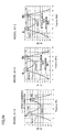
- FIG. 41 includes a diagram showing a structure of a wireless power supply system related to a sixth example, a graph indicating transmission characteristic S 21 resulting from measurement in the sixth example, and a diagram showing distribution of magnetic field strength related to the sixth example.
- FIG. 42 is an explanatory diagram of a wireless power supply system related to an embodiment 2.
- FIG. 43 is an explanatory diagram of a wireless power supply system.
- FIG. 44 is an explanatory diagram of a wireless power supply system.
- a method of the present invention for forming a magnetic field space is implemented in, for example, a wireless power supply system 200 shown in FIG. 1 .
- the wireless power supply system 200 essentially includes: a power-supplying module 202 having a power-supplying coil 21 and a power-supplying resonator 22 ; and a power-receiving module 203 having a power-receiving coil 31 and a power-receiving resonator 32 .
- the power-supplying resonator 22 and the power-receiving resonator 32 each adopt a solenoid coil.
- the power-supplying resonator 22 and the power-receiving resonator 32 are arranged so that their coil surfaces face each other.
- a cylindrical magnetic member 23 which covers the inner circumferential surface of the coil is arranged.
- the magnetic member 33 is arranged on the inner circumferential surface side of the coil of the power-receiving resonator 32 so as to cover the entire inner circumferential surface of the coil.
- the power-supplying coil 21 of the power-supplying module 202 and a later-described output terminal 111 of a network analyzer 110 are connected by wiring and are therefore capable of outputting AC power of any frequency from the output terminal 111 to the power-supplying coil 21 .
- the power-receiving coil 31 of the power-receiving module 203 and an input terminal 112 of the network analyzer 110 are connected by wiring so as to enable measurement of the power input to from the power-receiving coil 31 to the input terminal 112 .
- Power transmission is conducted from the power-supplying resonator 22 of the power-supplying module 202 to the power-receiving resonator 32 of the power-receiving module 203 by means of resonance therebetween while varying the magnetic field. Magnetic fields generated around the power-supplying resonator 22 and the power-receiving resonator 32 is shielded by the magnetic members 23 and 33 .
- a magnetic field space Z is formed on the inner circumferential surface sides (desirable location) of the coils of the power-supplying resonator 22 and the power-receiving resonator 32 .
- the magnetic field space Z thus formed has a smaller magnetic field strength than that in areas other than the inner circumferential surface sides of the coils.
- the power-supplying resonator 22 and the power-receiving resonator 32 are each a resonator adopting a coil, and examples thereof include a spiral coil, a solenoid coil, and a loop coil. Further, the “resonance” is a phenomenon in which two or more coils are tuned to a resonance frequency. Arrangement of the coils to face each other means arranging the coils so that their coil surfaces do not perpendicularly cross each other, where each of the coil surfaces is a cross section of the coil taken along its radial direction.
- the “desirable location” means a space on the inner circumference side or the outer circumference side of the coil (power-supplying resonator 22 ) of the power-supplying module 202 or the coil (power-receiving resonator 32 ) of the power-receiving module 203 .
- a wireless power supply system 100 having the power-supplying module 102 and the power-receiving module 103 each of which having no magnetic member as shown in FIG. 2 was used for forming the magnetic field space Z.
- variation in the magnetic field strength and that in the transmission characteristic “S 21 ” were measured.
- the measurement was conducted with a metal piece arranged on the inner circumference side of the coil of the power-receiving resonator 32 , and without the metal piece.
- a wireless power supply system 200 as shown in FIG. 5 having a power-supplying module 202 and the power-receiving module 203 respectively having a power-supplying resonator 22 and a power-receiving resonator 32 was used.
- cylindrical magnetic members 23 and 33 were arranged respectively to cover the entire inner circumferential surfaces of the resonators.
- the magnetic field space Z was formed, and for this magnetic field space Z, variation in the magnetic field strength and that in the transmission characteristic “S 21 ” were measured. The measurement was conducted with a metal piece arranged on the inner circumference side of the coil of the power-receiving resonator 32 , and without the metal piece.
- a wireless power supply system 300 as shown in FIG. 8 having a power-supplying module 302 and the power-receiving module 303 respectively having a power-supplying resonator 22 and a power-receiving resonator 32 was used.
- cylindrical magnetic members 23 and 33 were arranged respectively to cover the entire inner circumferential surfaces of the resonators.
- cylindrical magnetic members 24 and 34 were provided to cover the entire outer circumferential surfaces of the power-supplying resonator 22 and the power-receiving resonator 32 .
- this wireless power supply system 300 uses this wireless power supply system 300 the magnetic field space Z was formed, and for this magnetic field space Z, variation in the magnetic field strength and that in the transmission characteristic “S 21 ” were measured.
- the measurement was conducted with a metal piece arranged on the inner circumference side of the coil of the power-receiving resonator 32 , and without the metal piece.
- a wireless power supply system 400 as shown in FIG. 11 having a power-supplying module 402 and the power-receiving module 403 respectively having a power-supplying resonator 22 and a power-receiving resonator 32 was used.
- cylindrical magnetic members 23 and 33 were arranged respectively to cover the entire inner circumferential surfaces of the resonators.
- cylindrical magnetic members 24 and 34 were provided to cover the entire outer circumferential surfaces of the power-supplying resonator 22 and the power-receiving resonator 32 .
- ring-shaped magnetic members 25 and 35 were provided to cover the side surfaces of the power-supplying resonator 22 and the power-receiving resonator 32 opposite to the surfaces of the resonators facing each other.
- the magnetic field space Z was formed, and for this magnetic field space Z, variation in the magnetic field strength and that in the transmission characteristic “S 21 ” were measured.
- the measurement was conducted with a metal piece arranged on the inner circumference side of the coil of the power-receiving resonator 32 , and without the metal piece.
- the wireless power supply system 100 used in the comparative example includes: the power-supplying module 102 having the power-supplying coil 21 and the power-supplying resonator 22 ; and the power-receiving module 103 having the power-receiving coil 31 and the power-receiving resonator 32 , as shown in FIG. 2 .
- To the power-supplying coil 21 was connected an output terminal 111 of a network analyzer 110 (produced by Agilent Technologies, Inc.).
- To the power-receiving coil 31 was connected an input terminal 112 of the network analyzer 110 .
- the network analyzer 110 is capable of outputting from its output terminal 111 AC power of any given frequency to the power-supplying coil 21 .
- the network analyzer 110 is also capable of measuring the power input from the power-receiving coil 31 to the input terminal 112 . Further, the network analyzer 110 is also capable of measuring the transmission characteristic “S 21 ” shown in FIG. 3 .
- the power-supplying coil 21 plays a role of supplying power obtained from the network analyzer 110 to the power-supplying resonator 22 by means of electromagnetic induction.
- the power-supplying coil 21 was formed by winding once a copper wire material (coated by insulation film) having a wire diameter of 1 mm ⁇ , and its coil diameter was set to 100 mm ⁇ .
- the power-receiving coil 31 plays a role of outputting the power transmitted as magnetic field energy from the power-supplying resonator 22 to the power-receiving resonator 32 to the input terminal 112 of the network analyzer 110 by means of electromagnetic induction.
- This power-receiving coil 31 as in the case of the power-supplying coil 21 , was formed by winding once a copper wire material (coated by insulation film) having a wire diameter of 1 mm ⁇ , and its coil diameter was set to 100 mm ⁇ .
- the power-supplying resonator 22 and the power-receiving resonator 32 are each an LC resonance circuit, and play a role of creating the magnetic field resonant state.
- the capacitor component of the LC resonance circuit was realized in the form of an element.
- the capacitor component may be a stray capacitance realized by making the both ends of the coil open.
- the power-supplying resonator 22 and the power-receiving resonator 32 were each a solenoid coil formed by winding three times a copper wire material (coated by insulation film) having a wire diameter of 1 mm ⁇ , with its coil diameter being 100 mm ⁇ .
- the resonance frequency of the power-supplying resonator 22 and the power-receiving resonator 32 was set to 13.0 MHz.
- the power-supplying resonator 22 and the power-receiving resonator 32 were arranged so that their coil surfaces face each other in parallel.
- the magnetic field resonant state is formed between the power-supplying resonator 22 and the power-receiving resonator 32 .
- the magnetic field resonant state between the power-supplying resonator 22 and the power-receiving resonator 32 resonating with each other, power transmission from the power-supplying resonator 22 to the power-receiving resonator 32 as the magnetic field energy becomes possible.
- the distance A between the power-supplying coil 21 and the power-supplying resonator 22 was set to 15 mm
- the distance B between the power-receiving coil 31 and the power-receiving resonator 32 was set to 15 mm
- the distance C between the power-supplying resonator 22 and the power-receiving resonator 32 was set to 30 mm (see FIG. 2 ).
- a circular aluminum piece 60 made of aluminum having a thickness of 20 mm and a diameter of 76 mm ⁇ was used as the metal piece to be arranged on the coil inner circumference side of the power-receiving resonator 32 .
- a circular aluminum piece 60 made of aluminum having a thickness of 20 mm and a diameter of 58 mm ⁇ was used.
- the following describes variation in the magnetic field strength and the transmission characteristic “S 21 ” measured for the magnetic field space Z formed by the wireless power supply system 100 of the comparative example.
- the measurement was conducted with the aluminum piece 60 arranged on the inner circumference side of the coil of the power-receiving resonator 32 , and without the aluminum piece 60 . Note that, an electromagnetic field analysis was conducted to measure the magnetic field strength in the magnetic field space Z, and the magnetic field strengths are expressed in different color tones.
- the transmission characteristic “S 21 ” was measured without the aluminum piece 60 arranged on the inner circumference side of the coil of the power-receiving resonator 32 , with various frequencies of the AC power to the wireless power supply system 100 .
- the horizontal axis indicates the frequency of the AC power output from the output terminal 111
- the vertical axis indicates the transmission characteristic “S 21 ”.
- the transmission characteristic “S 21 ” is indicated in units of decibel and indicates signals out of those from the output terminal 111 having passed the input terminal 112 . Therefore, the higher the value, the higher the power transmission efficiency is. Further, the power transmission efficiency is a ratio of the power output to the input terminal 112 , for the power supplied from the output terminal 111 to the power-supplying module, while the wireless power supply system 101 is connected to the network analyzer 110 . The higher the transmission characteristic “S 21 ”, the higher the power transmission efficiency.
- the transmission characteristic “S 21 ” measured results in a waveform 141 having separate peaks on a low frequency side and a high frequency side as shown in FIG. 3 .
- the frequency on the high frequency side is indicated as fH
- the frequency on the low frequency side is indicated as fL.
- a magnetic field space Z 153 with a relatively small magnetic field strength, which is less influenced by the magnetic field is confirmed around the inner circumference sides of the power-supplying resonator 22 and the power-receiving resonator 32 .
- the resonance state in which the current in the coil (power-supplying resonator 22 ) of the power-supplying module and the current in the coil (power-receiving resonator 32 ) of the power-receiving module flow opposite directions to each other is referred to as antiphase resonance mode.
- the transmission characteristic “S 21 ” was measured with the aluminum piece 60 arranged on the inner circumference side of the coil of the power-receiving resonator 32 , with various frequencies of the AC power to the wireless power supply system 100 .
- the measurement results are shown in FIG. 3 as a waveform 142 representing the transmission characteristic “S 21 ” measured with the aluminum piece 60 arranged on the inner circumference side of the power-receiving resonator 32 . It should be understood from the waveform 142 that the transmission characteristic “S 21 ” significantly lowers at the frequency fL nearby the peak on the low frequency side, as compared with the waveform 141 of the transmission characteristic “S 21 ” in the case of not arranging the aluminum piece 60 on the inner circumference side of the coil of the power-receiving resonator 32 .
- the transmission characteristic “S 21 ” significantly lowers at the frequency fH nearby the peak on the high frequency side, as compared with the waveform 141 of the transmission characteristic “S 21 ” in the case of not arranging the aluminum piece 60 on the inner circumference side of the coil of the power-receiving resonator 32 .
- FIG. 4 (C) The distribution of magnetic field strength in the inphase resonance mode with the aluminum piece 60 on the inner circumference side of the coil of the power-receiving resonator 32 is shown in FIG. 4 (C). Further, the distribution of magnetic field strength in the antiphase resonance mode with the aluminum piece 60 on the inner circumference side of the coil of the power-receiving resonator 32 is shown in FIG. 4 (D).
- the distribution of the magnetic field strength is directly influenced by the aluminum piece 60 .
- the aluminum piece 60 is directly influenced by the magnetic field generated in the wireless power supply system 100 .
- the wireless power supply system 200 used in the example 1 includes: a power-supplying module 202 and a power-receiving module 203 .
- the power-supplying module 202 includes: a power-supplying coil 21 , a power-supplying resonator 22 , and a cylindrical magnetic member 23 which covers the inner circumferential surface of the coil of the power-supplying resonator 22 .
- the power-receiving module 203 includes: a power-receiving coil 31 , a power-receiving resonator 32 , and a cylindrical magnetic member 33 which covers the entire surface of the inner circumferential surface of the coil of the power-receiving resonator 32 .
- the power-supplying coil 21 is connected to the output terminal 111 of the network analyzer 110
- the power-receiving coil 31 is connected to the input terminal 112 of the network analyzer 110 .
- the magnetic members 23 and 33 are made of a resin in which magnetic powder was dispersed therein.
- the resin used for the magnetic members 23 and 33 may be a thermosetting resin or a thermoplastic resin, and is not particularly limited.
- examples of a thermosetting resin adoptable includes epoxy resin, phenol resin, melamine resin, vinyl ester resin, cyano ester resin, maleimide resin, silicon resin, and the like.
- examples of a thermoplastic resin include acrylic resin, vinyl acetate based resin, poly vinyl alcohol based resin, and the like. In this example, a resin whose main constituent is epoxy resin was adopted.
- the soft magnetic powder is not particularly limited.
- pure Fe, Fe—Si, Fe—Al—Si (sendust), Fe—Ni (permalloy), soft ferrites, Fe-base amorphous powder, Co-base amorphous powder, Fe—Co (permendur), and the like are adoptable.
- the magnetic members 23 and 33 had a cylindrical shape with a thickness of 1 mm, an outer diameter of 80 mm ⁇ , and an inner diameter of 78 mm. Its magnetic permeability was 100.
- the structures, other than those described above, were similar to that of the wireless power supply system 100 related to the comparative example.
- the transmission characteristic “S 21 ” was measured without the aluminum piece 60 arranged on the inner circumference side of the coil of the power-receiving resonator 32 , with various frequencies of the AC power to the wireless power supply system 200 .
- the transmission characteristic “S 21 ” measured results in a waveform 241 having separate peaks on a low frequency side and a high frequency side as shown in FIG. 6 .
- FIG. 7 (A) The distribution of the magnetic field strength in the case of setting the frequency of the AC power to the power-supplying module 202 to the frequency fL nearby the peak on the low frequency side (inphase resonance mode) is shown in FIG. 7 (A). It should be understood from the distribution of magnetic field strength shown in FIG. 7 (A) that the influence of the magnetic field is weakened around the outer circumference sides of the power-supplying resonator 22 and the power-receiving resonator 32 , and a magnetic field space Z 251 having a relatively small magnetic field strength is confirmed. Further, a magnetic field space Z 252 with magnetic field strength less influenced by the magnetic field was confirmed on the inner circumference side of each of the power-supplying resonator 22 and the power-receiving resonator 32 .
- FIG. 7 (B) the distribution of the magnetic field strength in the case of setting the frequency of the AC power to the power-supplying module 202 to the frequency fH nearby the peak on the high frequency side (antiphase resonance mode) is shown in FIG. 7 (B). From the distribution of magnetic field strength shown in FIG. 7 (B), a magnetic field space Z 253 with a relatively small magnetic field strength, which is less influenced by the magnetic field is confirmed around the inner circumference sides of the power-supplying resonator 22 and the power-receiving resonator 32 .
- a magnetic field space Z 253 whose magnetic field strength is relatively smaller than that in the comparative example on the inner circumference side of each of the power-supplying resonator 22 and the power-receiving resonator 32 , in the antiphase resonance mode.
- the magnetic field space Z 253 formed in the antiphase resonance mode was broader than the magnetic field space Z 252 formed in the inphase resonance mode.
- the transmission characteristic “S 21 ” was measured with the aluminum piece 60 arranged on the inner circumference side of the coil of the power-receiving resonator 32 , with various frequencies of the AC power to the wireless power supply system 200 .
- the measurement results are shown in FIG. 6 as a waveform 242 representing the transmission characteristic “S 21 ” measured with the aluminum piece 60 arranged on the inner circumference side of the power-receiving resonator 32 .
- the transmission characteristic “S 21 ” at the frequency fL nearby the peak on the low frequency side shown by the waveform 242 is slightly lower than the transmission characteristic “S 21 ” shown by the waveform 241 resulted with no aluminum piece 60 on the inner circumference side of the coil of the power-receiving resonator 32 , it should be understood the transmission characteristic itself is maintained at a high value.
- the transmission characteristic “S 21 ” at the frequency fH nearby the peak on the high frequency side is substantially the same as the transmission characteristic “S 21 ” shown by the waveform 241 resulting without no aluminum piece 60 on the inner circumference side of the coil of the power-receiving resonator 32 (see point P in FIG. 6 ).
- FIG. 7 (C) The distribution of magnetic field strength in the inphase resonance mode with the aluminum piece 60 on the inner circumference side of the coil of the power-receiving resonator 32 is shown in FIG. 7 (C). Further, the distribution of magnetic field strength in the antiphase resonance mode with the aluminum piece 60 on the inner circumference side of the coil of the power-receiving resonator 32 is shown in FIG. 7(D) . It should be understood from these figures, when the aluminum piece 60 is arranged on the inner circumference sides of the coils of the power-receiving resonator 32 in the wireless power supply system 200 related to the example 1, the distribution of the magnetic field strength is not influenced so much by the aluminum piece 60 , as compared with the comparative example.
- the magnetic members 23 and 33 blocks the magnetic field generated around the power-supplying resonator 22 and the power-receiving resonator 32 , and the magnetic field space Z 253 greater than the magnetic field space Z 153 of the comparative example is formed on the inner circumference side of the coil of the power-supplying resonator 22 and the power-receiving resonator 32 .
- the aluminum piece 60 is less influenced by the magnetic field generated in the wireless power supply system 200 .
- the wireless power supply system 300 used in the example 2 includes: a power-supplying module 302 and a power-receiving module 303 .
- the power-supplying module 302 includes: a power-supplying coil 21 , a power-supplying resonator 22 , a cylindrical magnetic member 23 which covers the entire inner circumferential surface of the coil of the power-supplying resonator 22 , and a cylindrical magnetic member 24 which covers the entire outer circumferential surface of the coil of the power-supplying resonator 22 .
- the power-receiving module 303 includes: a power-receiving coil 31 , a power-receiving resonator 32 , and a cylindrical magnetic member 33 which covers the entire inner circumferential surface of the coil of the power-receiving resonator 32 , and a cylindrical magnetic member 34 which covers the entire outer circumferential surface of the coil of the power-receiving resonator 32 .
- the power-supplying coil 21 was connected to the output terminal 111 of the network analyzer 110
- the power-receiving coil 31 was connected to the input terminal 112 of the network analyzer 110 .
- the magnetic members 24 and 34 were made of a resin in which the magnetic powder was dispersed as in the case of the magnetic members 23 and 33 of the example 1.
- the magnetic members 24 and 34 each had a cylindrical shape, with a thickness of 1 mm, an outer diameter of 120 mm ⁇ , and an inner diameter of 118 mm ⁇ , and its magnetic permeability was 100.
- the structures, other than those described above, were similar to that of the wireless power supply system 200 related to the example 1.
- the transmission characteristic “S 21 ” was measured without the aluminum piece 60 arranged on the inner circumference side of the coil of the power-receiving resonator 32 , with various frequencies of the AC power to the wireless power supply system 300 .
- the transmission characteristic “S 21 ” measured results in a waveform 341 having separate peaks on a low frequency side and a high frequency side as shown in FIG. 9 .
- FIG. 10 (A) The distribution of the magnetic field strength in the case of setting the frequency of the AC power to the power-supplying module 302 to the frequency fL nearby the peak on the low frequency side (inphase resonance mode) is shown in FIG. 10 (A). From the distribution of magnetic field strength shown in FIG. 10(B) , a magnetic field space Z 352 with slightly less influence of the magnetic field to its magnetic field strength is confirmed on the inner circumference sides of the power-supplying resonator 22 and the power-receiving resonator 32 .
- FIG. 10 (B) the distribution of the magnetic field strength in the case of setting the frequency of the AC power to the power-supplying module 302 to the frequency fH nearby the peak on the high frequency side (antiphase resonance mode) is shown in FIG. 10 (B). From the distribution of magnetic field strength shown in FIG. 10 (B), a magnetic field space Z 353 with a relatively small magnetic field strength, which is less influenced by the magnetic field is confirmed around the inner circumference sides of the power-supplying resonator 22 and the power-receiving resonator 32 .
- a magnetic field space Z 353 whose magnetic field strength is relatively smaller than that in the comparative example on the inner circumference side of each of the power-supplying resonator 22 and the power-receiving resonator 32 , in the antiphase resonance mode.
- the magnetic field space Z 353 formed in the antiphase resonance mode was broader than the magnetic field space Z 352 formed in the inphase resonance mode.
- the transmission characteristic “S 21 ” was measured with the aluminum piece 60 arranged on the inner circumference side of the coil of the power-receiving resonator 32 , with various frequencies of the AC power to the wireless power supply system 300 .
- the measurement results are shown in FIG. 9 as a waveform 342 representing the transmission characteristic “S 21 ” measured with the aluminum piece 60 arranged on the inner circumference side of the coil of the power-receiving resonator 32 .
- the transmission characteristic “S 21 ” at the frequency fL nearby the peak on the low frequency side shown by the waveform 342 is slightly lower than the transmission characteristic “S 21 ” shown by the waveform 341 resulted with no aluminum piece 60 on the inner circumference side of the coil of the power-receiving resonator 32 , it should be understood the transmission characteristic itself is maintained at a high value.
- the transmission characteristic “S 21 ” at the frequency fH nearby the peak on the high frequency side is substantially the same as the transmission characteristic “S 21 ” shown by the waveform 341 resulting without no aluminum piece 60 on the inner circumference side of the coil of the power-receiving resonator 32 (see point P in FIG. 9 ).
- FIG. 10 (C) The distribution of magnetic field strength in the inphase resonance mode with the aluminum piece 60 on the inner circumference side of the coil of the power-receiving resonator 32 is shown in FIG. 10 (C). Further, the distribution of the magnetic field strength in the antiphase resonance mode with the aluminum piece 60 on the inner circumference side of the coil of the power-receiving resonator 32 is shown in FIG. 10 (D). It should be understood from these figures, when the aluminum piece 60 is arranged on the inner circumference sides of the coils of the power-receiving resonator 32 in the wireless power supply system 300 related to the example 2, the distribution of the magnetic field strength is not influenced so much by the aluminum piece 60 , as compared with the comparative example.
- the magnetic members 23 and 33 and the magnetic members 24 and 34 block the magnetic field generated around the power-supplying resonator 22 and the power-receiving resonator 32 , and the magnetic field space Z 353 greater than the magnetic field space Z 153 of the comparative example is formed on the inner circumference side of the coil of the power-supplying resonator 22 and the power-receiving resonator 32 .
- the aluminum piece 60 was less influenced by the magnetic field generated in the wireless power supply system 300 .
- the magnetic field space Z 353 formed by the wireless power supply system 300 of the example 2 was broader than the magnetic field space Z 253 formed by the wireless power supply system 200 related to the example 1. This is because, in the wireless power supply system 300 related to the example 2, the cylindrical magnetic members 24 and 34 which cover the entire outer circumferential surfaces of the coils of the power-supplying resonator 22 and the power-receiving resonator 32 blocks the magnetic field generated on the outer circumferential sides of the power-supplying resonator 22 and the power-receiving resonator 32 .
- the wireless power supply system 400 used in the example 3 includes: a power-supplying module 402 and a power-receiving module 403 .
- the power-supplying module 402 includes: a power-supplying coil 21 , a power-supplying resonator 22 , a cylindrical magnetic member 23 which covers the entire inner circumferential surfaces of the coils of the power-supplying coil 21 and the power-supplying resonator 22 , a cylindrical magnetic member 24 which covers the entire outer circumferential surfaces of the coils of the power-supplying coil 21 and the power-supplying resonator 22 , and a ring-shaped magnetic member 25 which covers a side surface of the coil of the power-supplying resonator 22 opposite to the surface facing the power-receiving resonator 32 .
- the power-receiving module 403 includes: a power-receiving coil 31 , a power-receiving resonator 32 , a cylindrical magnetic member 33 which covers the entire inner circumferential surfaces of the coils of the power-receiving coil 31 and the power-receiving resonator 32 , a cylindrical magnetic member 34 which covers the entire outer circumferential surfaces of the coils of the power-receiving coil 31 and the power-receiving resonator 32 , and a ring-shaped magnetic member 35 which covers a side surface of the coil of the power-receiving resonator 32 opposite to the surface facing the power-supplying resonator 22 .
- the power-supplying coil 21 was connected to the output terminal 111 of the network analyzer 110
- the power-receiving coil 31 was connected to the input terminal 112 of the network analyzer 110 .
- the magnetic members 25 and 35 were made of a resin in which the magnetic powder was dispersed as in the case of the magnetic members 23 and 33 of the example 1.
- the magnetic members 25 and 35 each had a shape of an O-ring, with a thickness of 1 mm, an outer diameter of 120 mm, and an inner diameter of 80 mm, and its magnetic permeability was 100.
- the structures, other than those described above, were similar to that of the wireless power supply system 300 related to the example 2.
- the transmission characteristic “S 21 ” was measured without the aluminum piece 60 arranged on the inner circumference side of the coil of the power-receiving resonator 32 , with various frequencies of the AC power to the wireless power supply system 300 .
- the transmission characteristic “S 21 ” measured results in a waveform 441 having separate peaks on a low frequency side and a high frequency side as shown in FIG. 12 .
- FIG. 13(A) The distribution of the magnetic field strength in the case of setting the frequency of the AC power to the power-supplying module 402 to the frequency fL nearby the peak on the low frequency side (inphase resonance mode) is shown in FIG. 13(A) . From the distribution of magnetic field strength shown in FIG. 13(B) , a magnetic field space Z 452 with slightly less influence of the magnetic field to its magnetic field strength is confirmed on the inner circumference sides of the power-supplying resonator 22 and the power-receiving resonator 32 .
- FIG. 13 (B) the distribution of the magnetic field strength in the case of setting the frequency of the AC power to the power-supplying module 402 to the frequency fH nearby the peak on the high frequency side (antiphase resonance mode) is shown in FIG. 13 (B). From the distribution of magnetic field strength shown in FIG. 13(B) , a magnetic field space Z 453 with a relatively small magnetic field strength, which is less influenced by the magnetic field is confirmed around the inner circumference sides of the power-supplying resonator 22 and the power-receiving resonator 32 .
- a magnetic field space Z 453 whose magnetic field strength is relatively smaller than that in the comparative example on the inner circumference side of each of the power-supplying resonator 22 and the power-receiving resonator 32 , in the antiphase resonance mode.
- the magnetic field space Z 453 formed in the antiphase resonance mode was broader than the magnetic field space Z 452 formed in the inphase resonance mode.
- the transmission characteristic “S 21 ” was measured with the aluminum piece 60 arranged on the inner circumference side of the coil of the power-receiving resonator 32 , with various frequencies of the AC power to the wireless power supply system 400 .
- the measurement results are shown in FIG. 12 as a waveform 442 representing the transmission characteristic “S 21 ” measured with the aluminum piece 60 arranged on the inner circumference side of the coil of the power-receiving resonator 32 .
- the transmission characteristic “S 21 ” at the frequency fL nearby the peak on the low frequency side shown by the waveform 442 is maintained at substantially the same value as the transmission characteristic “S 21 ” shown by the waveform 441 resulted with no aluminum piece 60 on the inner circumference side of the coil of the power-receiving resonator 32 .
- the transmission characteristic “S 21 ” at the frequency fH nearby the peak on the high frequency side was also maintained at substantially the same value as the transmission characteristic “S 21 ” shown by the waveform 441 resulting with no aluminum piece 60 on the inner circumference side of the coil of the power-receiving resonator 32 (see point P on FIG. 12 ).
- FIG. 13(C) The distribution of magnetic field strength in the inphase resonance mode with the aluminum piece 60 on the inner circumference side of the coil of the power-receiving resonator 32 is shown in FIG. 13(C) . Further, the distribution of magnetic field strength in the antiphase resonance mode with the aluminum piece 60 on the inner circumference side of the coil of the power-receiving resonator 32 is shown in FIG. 13(D) . It should be understood from these figures, when the aluminum piece 60 is arranged on the inner circumference sides of the coils of the power-receiving resonator 32 in the wireless power supply system 400 related to the example 3, the distribution of the magnetic field strength is not influenced so much by the aluminum piece 60 , as compared with the comparative example.
- the magnetic members 23 and 33 , the magnetic members 24 and 34 , and the magnetic members 25 and 35 block the magnetic field generated around the power-supplying resonator 22 and the power-receiving resonator 32 , and the magnetic field space Z 453 greater than the magnetic field space Z 153 of the comparative example is formed on the inner circumference side of the coil of the power-supplying resonator 22 and the power-receiving resonator 32 .
- the aluminum piece 60 was less influenced by the magnetic field generated in the wireless power supply system 400 .
- the magnetic field space Z 353 formed by the wireless power supply system 300 of the example 2 was broader than the magnetic field space Z 453 formed by the wireless power supply system 400 related to the example 3. This is because, in the wireless power supply system 400 related to the example 3, the cylindrical magnetic members 25 and 35 which cover the side surfaces of the coils of the power-supplying resonator 22 and the power-receiving resonator 32 blocks the magnetic field generated on the side surfaces of the power-supplying resonator 22 and the power-receiving resonator 32 .
- the structures of the wireless power supply system 500 of the example 4 are the same as those of the wireless power supply system 200 of the example 1, except in that the magnetic members 123 and 133 adopted in the wireless power supply system 500 each has a thickness of 10 mm, whereas the magnetic members 23 and 33 in the wireless power supply system 200 of the example 1 each has a thickness of 1 mm (see FIG. 15 ).
- variation in the magnetic field strength and variation in the transmission characteristic “S 21 ” were measured with and without the aluminum piece 60 on the inner circumference side of the coil of the power-receiving resonator 32 .
- the transmission characteristic “S 21 ” of the wireless power supply system 500 related to the example 4 was measured with the aluminum piece 60 on the inner circumference side of the coil of the power-receiving resonator 32 , with various frequencies of the AC power to the wireless power supply system 500 .
- the transmission characteristic “S 21 ” measured results in a waveform 541 having separate peaks on a low frequency side and a high frequency side as shown in FIG. 14 .
- FIG. 15(A) The distribution of the magnetic field strength in the case of setting the frequency of the AC power to the power-supplying module 502 to the frequency fL nearby the peak on the low frequency side (inphase resonance mode) is shown in FIG. 15(A) . From the distribution of magnetic field strength shown in FIG. 15(A) , a magnetic field space Z 552 with a magnetic field strength less influenced by the magnetic field is confirmed around the inner circumference sides of the power-supplying resonator 22 and the power-receiving resonator 32 .
- the wireless power supply system 500 related to the example 4 forms a magnetic field space Z 552 broader than the magnetic field space Z 252 formed by the wireless power supply system 200 related to the example 1, on the inner circumference sides of the power-supplying resonator 22 and the power-receiving resonator 32 .
- the magnetic members 123 and 133 covering the inner circumferential surfaces of the power-supplying resonator 22 and the power-receiving resonator 32 is thicker than the example 1, and this enables more reliable blocking of the magnetic field generated on the inner circumferential surface side of the power-supplying resonator 22 and the power-receiving resonator 32 .
- FIG. 15(B) the distribution of the magnetic field strength in the case of setting the frequency of the AC power to the power-supplying module 502 to the frequency fH nearby the peak on the high frequency side (antiphase resonance mode) is shown in FIG. 15(B) . From the distribution of magnetic field strength shown in FIG. 15(B) , a magnetic field space Z 553 with a relatively small magnetic field strength, which is less influenced by the magnetic field is confirmed around the inner circumference sides of the power-supplying resonator 22 and the power-receiving resonator 32 .
- the magnetic field space Z 553 broader than the magnetic field space Z 253 formed by the wireless power supply system 200 related to the example 1, on the inner circumference sides of the power-supplying resonator 22 and the power-receiving resonator 32 .
- the magnetic members 123 and 133 covering the inner circumferential surfaces of the power-supplying resonator 22 and the power-receiving resonator 32 is thicker than the example 1, and this enables more reliable blocking of the magnetic field generated on the inner circumferential surface side of the power-supplying resonator 22 and the power-receiving resonator 32 .
- the magnetic field space Z 553 formed in the antiphase resonance mode was broader than the magnetic field space Z 552 formed in the inphase resonance mode.
- the transmission characteristic “S 21 ” was measured with the aluminum piece 60 arranged on the inner circumference side of the coil of the power-receiving resonator 32 , with various frequencies of the AC power to the wireless power supply system 500 .
- the measurement results are shown in FIG. 14 as a waveform 542 representing the transmission characteristic “S 21 ” measured with the aluminum piece 60 arranged on the inner circumference side of the coil of the power-receiving resonator 32 .
- the transmission characteristic “S 21 ” at the frequency fL nearby the peak on the low frequency side shown by the waveform 542 is maintained at substantially the same value as the transmission characteristic “S 21 ” shown by the waveform 541 resulted with no aluminum piece 60 on the inner circumference side of the coil of the power-receiving resonator 32 (see point P 1 of FIG. 14 ).
- the transmission characteristic “S 21 ” at the frequency fH nearby the peak on the high frequency side was also maintained at substantially the same value as the transmission characteristic “S 21 ” shown by the waveform 541 resulting with no aluminum piece 60 on the inner circumference side of the coil of the power-receiving resonator 32 (see point P 2 on FIG. 14 ).
- FIG. 15(C) The distribution of magnetic field strength in the inphase resonance mode with the aluminum piece 60 on the inner circumference side of the coil of the power-receiving resonator 32 is shown in FIG. 15(C) . Further, the distribution of magnetic field strength in the antiphase resonance mode with the aluminum piece 60 on the inner circumference side of the coil of the power-receiving resonator 32 is shown in FIG. 15(D) . It should be understood from these figures, when the aluminum piece 60 is arranged on the inner circumference sides of the coils of the power-receiving resonator 32 in the wireless power supply system 500 related to the example 4, the distribution of the magnetic field strength has little influence from the aluminum piece 60 , as compared with the example 1.
- each of the magnetic members 123 and 133 which cover the inner circumferential surfaces of the power-supplying resonator 22 and the power-receiving resonator 32 enables formation of relatively large magnetic field spaces Z 552 and Z 553 on the inner circumference sides of the coils of the power-supplying resonator 22 and the power-receiving resonator 32 , when power transmission is conducted between the power-supplying module 502 and the power-receiving module 503 .
- the structures of the wireless power supply system 600 in the example 5 are the same as those of the wireless power supply system 300 related to the example 2 except in that the magnetic members 23 and 33 adopted in the wireless power supply system 600 each has a thickness of 10 mm, whereas the magnetic members 123 and 133 adopted in the wireless power supply system 300 each has a thickness of 1 mm (see FIG. 17 ).
- variations in the magnetic field strength and the transmission characteristic “S 21 ” were measured with and without the aluminum piece 60 on the inner circumference side of the coil of the power-receiving resonator 32 .
- the transmission characteristic “S 21 ” was measured without the aluminum piece 60 arranged on the inner circumference side of the coil of the power-receiving resonator 32 , with various frequencies of the AC power to the wireless power supply system 600 .
- the transmission characteristic “S 21 ” measured results in a waveform 641 having separate peaks on a low frequency side and a high frequency side as shown in FIG. 16 .
- FIG. 17 (A) The distribution of the magnetic field strength in the case of setting the frequency of the AC power to the power-supplying module 602 to the frequency fL nearby the peak on the low frequency side (inphase resonance mode) is shown in FIG. 17 (A). From the distribution of magnetic field strength shown in FIG. 17(A) , a magnetic field space Z 652 with a magnetic field strength less influenced by the magnetic field is confirmed around the inner circumference sides of the power-supplying resonator 22 and the power-receiving resonator 32 .
- the wireless power supply system 600 related to the example 5 forms a magnetic field space Z 652 broader than the magnetic field space Z 352 formed by the wireless power supply system 300 related to the example 2, on the inner circumference sides of the power-supplying resonator 22 and the power-receiving resonator 32 .
- the magnetic members 123 and 133 covering the inner circumferential surfaces of the power-supplying resonator 22 and the power-receiving resonator 32 is thicker than the example 2, and this enables more reliable blocking of the magnetic field generated on the inner circumferential surface side of the power-supplying resonator 22 and the power-receiving resonator 32 .
- FIG. 17(B) the distribution of the magnetic field strength in the case of setting the frequency of the AC power to the power-supplying module 602 to the frequency fH nearby the peak on the high frequency side (antiphase resonance mode) is shown in FIG. 17(B) . From the distribution of magnetic field strength shown in FIG. 17(B) , a magnetic field space Z 653 with a relatively small magnetic field strength, which is less influenced by the magnetic field is confirmed around the inner circumference sides of the power-supplying resonator 22 and the power-receiving resonator 32 .
- the magnetic field space Z 653 broader than the magnetic field space Z 353 formed by the wireless power supply system 300 related to the example 2, on the inner circumference sides of the power-supplying resonator 22 and the power-receiving resonator 32 .
- the magnetic members 123 and 133 covering the inner circumferential surfaces of the power-supplying resonator 22 and the power-receiving resonator 32 is thicker than the example 2, and this enables more reliable blocking of the magnetic field generated on the inner circumferential surface side of the power-supplying resonator 22 and the power-receiving resonator 32 .
- the magnetic field space Z 653 formed in the antiphase resonance mode was broader than the magnetic field space Z 652 formed in the inphase resonance mode.
- the transmission characteristic “S 21 ” was measured with the aluminum piece 60 arranged on the inner circumference side of the coil of the power-receiving resonator 32 , with various frequencies of the AC power to the wireless power supply system 600 .
- the measurement results are shown in FIG. 16 as a waveform 642 representing the transmission characteristic “S 21 ” measured with the aluminum piece 60 arranged on the inner circumference side of the coil of the power-receiving resonator 32 .
- the transmission characteristic “S 21 ” at the frequency fL nearby the peak on the low frequency side shown by the waveform 642 is maintained at substantially the same value as the transmission characteristic “S 21 ” shown by the waveform 641 resulted with no aluminum piece 60 on the inner circumference side of the coil of the power-receiving resonator 32 (see point P 1 of FIG. 16 ).
- the transmission characteristic “S 21 ” at the frequency fH nearby the peak on the high frequency side was also maintained at substantially the same value as the transmission characteristic “S 21 ” shown by the waveform 641 resulting with no aluminum piece 60 on the inner circumference side of the coil of the power-receiving resonator 32 (see point P 2 on FIG. 16 ).
- FIG. 17(C) The distribution of magnetic field strength in the inphase resonance mode with the aluminum piece 60 on the inner circumference side of the coil of the power-receiving resonator 32 is shown in FIG. 17(C) . Further, the distribution of magnetic field strength in the antiphase resonance mode with the aluminum piece 60 on the inner circumference side of the coil of the power-receiving resonator 32 is shown in FIG. 17(D) . It should be understood from these figures, when the aluminum piece 60 is arranged on the inner circumference sides of the coils of the power-receiving resonator 32 in the wireless power supply system 600 related to the example 5, the distribution of the magnetic field strength has little influence from the aluminum piece 60 , as compared with the example 2.
- each of the magnetic members 123 and 133 which cover the inner circumferential surfaces of the power-supplying resonator 22 and the power-receiving resonator 32 enables formation of relatively large magnetic field spaces Z 652 and Z 653 on the inner circumference sides of the coils of the power-supplying resonator 22 and the power-receiving resonator 32 , when power transmission is conducted between the power-supplying module 602 and the power-receiving module 603 .
- the power-supplying resonator of the power-supplying module and the power-receiving resonator of the power-receiving module were arranged to face each other, and quadrangular tubular magnetic members covering the entire inner circumferential surfaces of the coils of the power-supplying resonator and the power-receiving resonator were arranged on the inner circumferential surface sides of the coils. Then, magnetic field strength of a magnetic field space Z formed by this wireless power supply system was measured. This is described below as the second example.
- the wireless power supply system 1100 used in the second comparative example includes: a power-supplying module 1102 having a quadrangular power-supplying coil 1121 and a power-supplying resonator 1122 having a quadrangular tubular coil structure; and a power-receiving module 1103 having a quadrangular power-receiving coil 1131 and a power-receiving resonator 1132 having a quadrangular tubular coil structure.
- the power-supplying coil 1121 was connected to the output terminal 111 of the network analyzer 110
- the power-receiving coil 1131 was connected to the input terminal 112 of the network analyzer 110 .
- the power-supplying coil 1121 plays a role of supplying power obtained from the network analyzer 110 to the power-supplying resonator 1122 by means of electromagnetic induction.
- This power-supplying coil 1121 was formed in a square shape with each side being 100 mm, by winding once a copper wire material (coated by insulation film) having a wire diameter of 1 mm ⁇ .
- the power-receiving coil 1131 plays a role of outputting the power transmitted as magnetic field energy from the power-supplying resonator 1122 to the power-receiving resonator 1132 to the input terminal 112 of the network analyzer 310 by means of electromagnetic induction.
- This power-receiving coil 1131 was formed in a square shape with each side being 1.00 mm, by winding once a copper wire material (coated by insulation film) having a wire diameter of 1 mm ⁇ , as in the case of the power-supplying coil 1121 .
- the power-supplying resonator 1122 and the power-receiving resonator 1132 are each an LC resonance circuit, and play a role of creating the magnetic field resonant state.
- the power-supplying resonator 1122 and the power-receiving resonator 1132 each had a structure of a quadrangular tubular coil with each side of its cross section being 100 mm, and is formed by winding three times a copper wire material (coated by insulation film) having a wire diameter of 1 mm ⁇ .
- the distance between the power-supplying coil 1121 and the power-supplying resonator 1122 was set to be 15 mm
- the distance between the power-supplying resonator 1122 and the power-receiving resonator 1132 was set to be 30 mm
- the distance between the power-receiving resonator 1132 and the power-receiving coil 1131 was set to be 15 mm.
- the resonance frequency of the power-supplying resonator 1122 and the power-receiving resonator 1132 was set to 14.2 MHz.
- the power-supplying resonator 1122 and the power-receiving resonator 1132 were arranged so that their coil surfaces face each other in parallel.
- an aluminum piece 60 made of aluminum in a rectangular parallelepiped shape with a thickness of 20 mm and having a cross section with each side being 76 mm ⁇ was used as the metal piece to be arranged on the coil inner circumference side of the power-receiving resonator 1132 .
- the transmission characteristic “S 21 ” was measured without the aluminum piece 60 arranged on the inner circumference side of the coil of the power-receiving resonator 1132 , with various frequencies of the AC power to the wireless power supply system 1100 .
- the transmission characteristic “S 21 ” measured results in a waveform 1141 having separate peaks on a low frequency side and a high frequency side as shown in FIG. 19 .
- the frequency of the AC power to the power-supplying module 1102 was set to the frequency fL nearby the peak on the low frequency side (inphase resonance mode)
- the power-supplying resonator 1122 and the power-receiving resonator 1132 were resonant with each other in inphase, and the current in the power-supplying resonator 1122 and the current in the power-receiving resonator 1132 both flowed in the same direction.
- the distribution of the magnetic field strength in this inphase resonance mode is shown in FIG. 20 (A). It should be understood from the distribution of magnetic field strength shown in FIG.
- the frequency of the AC power to the power-supplying module 1102 was set to the frequency fH nearby the peak on the side of the high frequency side (antiphase resonance mode)
- the power-supplying resonator 1122 and the power-receiving resonator 1132 resonated with each other in antiphase
- the current in the power-supplying resonator 1122 and the current in the power-receiving resonator 1132 flowed opposite directions to each other.
- the distribution of magnetic field strengths in this antiphase resonance mode is shown in FIG. 20(B) . From the distribution of magnetic field strength shown in FIG.
- a magnetic field space Z 1153 with a relatively small magnetic field strength, which is less influenced by the magnetic field is confirmed around the inner circumference sides of the power-supplying resonator 1122 and the power-receiving resonator 1132 .
- the transmission characteristic “S 21 ” was measured with the aluminum piece 60 arranged on the inner circumference side of the coil of the power-receiving resonator 1132 , with various frequencies of the AC power to the wireless power supply system 1100 .
- the measurement results are shown in FIG. 19 as a waveform 1142 representing the transmission characteristic “S 21 ” measured with the aluminum piece 60 arranged on the inner circumference side of the coil of the power-receiving resonator 1132 . It should be understood from the waveform 1142 that the transmission characteristic “S 21 ” significantly lowers at the frequency fL nearby the peak on the low frequency side, as compared with the waveform 1141 of the transmission characteristic “S 21 ” in the case of not arranging the aluminum piece 60 on the inner circumference side of the coil of the power-receiving resonator 1132 .
- the transmission characteristic “S 21 ” significantly lowers at the frequency fH nearby the peak on the high frequency side, as compared with the waveform 1141 of the transmission characteristic “S 21 ” in the case of not arranging the aluminum piece 60 on the inner circumference side of the coil of the power-receiving resonator 1132 .
- FIG. 20(C) The distribution of magnetic field strength in the inphase resonance mode with the aluminum piece 60 on the inner circumference side of the coil of the power-receiving resonator 1132 is shown in FIG. 20(C) . Further, the distribution of magnetic field strength in the antiphase resonance mode with the aluminum piece 60 on the inner circumference side of the coil of the power-receiving resonator 1132 is shown in FIG. 20(D) .
- the distribution of the magnetic field strength is directly influenced by the aluminum piece 60 .
- the aluminum piece 60 is directly influenced by the magnetic field generated in the wireless power supply system 1100 .
- the wireless power supply system 1200 used in the second example included a power-supplying module 1202 and a power-receiving module 1203 .
- the power-supplying module 1202 included: a quadrangular power-supplying coil 1221 , a power-supplying resonator 1222 having a structure of a quadrangular tubular coil, and a quadrangular tubular magnetic member 1223 which covered the entire inner circumferential surface of the coil of the power-supplying resonator 1222 .
- the power-receiving module 1203 included: a quadrangular power-receiving coil 1231 , a power-receiving resonator 1232 having a structure of a quadrangular tubular coil, and a quadrangular tubular magnetic member 1233 which covered the entire circumferential surface of the coil of the power-receiving resonator 1232 .
- the power-supplying coil 1221 was connected to the output terminal 111 of the network analyzer 110
- the power-receiving coil 1231 was connected to the input terminal 112 of the network analyzer 110 .
- the magnetic members 1223 and 1233 are made of a resin in which magnetic powder was dispersed therein. These magnetic members 1223 and 1233 were formed in a shape of a quadrangular tube, with a thickness of 1 mm, a length of each outer side of 82 mm, a length of each inner side of 80 mm, and a height of 30 mm, and its magnetic permeability is 100.
- the structures of the power-supplying coil 1221 , the power-supplying resonator 1222 , the power-receiving coil 1231 , and the power-receiving resonator 1232 were the same as those in the wireless power supply system 1100 related to the second comparative example.
- the transmission characteristic “S 21 ” was measured without the aluminum piece 60 arranged on the inner circumference side of the coil of the power-receiving resonator 1232 , with various frequencies of the AC power to the wireless power supply system 1200 .
- the transmission characteristic “S 21 ” measured results in a waveform 1241 having separate peaks on a low frequency side and a high frequency side as shown in FIG. 22 .
- FIG. 23(A) The distribution of the magnetic field strength in the case of setting the frequency of the AC power to the power-supplying module 1202 to the frequency fL nearby the peak on the low frequency side (inphase resonance mode) is shown in FIG. 23(A) . It should be understood from the distribution of magnetic field strength shown in FIG. 23(A) that the influence of the magnetic field is weakened around the outer circumference sides of the power-supplying resonator 1222 and the power-receiving resonator 1232 , and a magnetic field space Z 1251 having a relatively small magnetic field strength is confirmed.
- a magnetic field space Z 1252 with magnetic field strength slightly less influenced by the magnetic field was confirmed on the inner circumference side of each of the power-supplying resonator 1222 and the power-receiving resonator 1232 .
- FIG. 23 (B) the distribution of the magnetic field strength in the case of setting the frequency of the AC power to the power-supplying module 1202 to the frequency fH nearby the peak on the high frequency side (antiphase resonance mode) is shown in FIG. 23 (B). From the distribution of magnetic field strength shown in FIG. 23(B) , a magnetic field space Z 1253 with a relatively small magnetic field strength, which is less influenced by the magnetic field is confirmed around the inner circumference sides of the power-supplying resonator 1222 and the power-receiving resonator 1232 .
- a magnetic field space Z 1253 whose magnetic field strength is relatively smaller than that in the second comparative example on the inner circumference side of each of the power-supplying resonator 1222 and the power-receiving resonator 1232 , in the antiphase resonance mode.
- the magnetic field space Z 1253 formed in the antiphase resonance mode was broader than the magnetic field space Z 1252 formed in the inphase resonance mode.
- the transmission characteristic “S 21 ” was measured with the aluminum piece 60 arranged on the inner circumference side of the coil of the power-receiving resonator 1232 , with various frequencies of the AC power to the wireless power supply system 1200 .
- the measurement results are shown in FIG. 22 as a waveform 1242 representing the transmission characteristic “S 21 ” measured with the aluminum piece 60 arranged on the inner circumference side of the coil of the power-receiving resonator 1232 .
- the transmission characteristic “S 21 ” at the frequency fL nearby the peak on the low frequency side shown by the waveform 1242 is slightly lower than the transmission characteristic “S 21 ” shown by the waveform 1241 resulted with no aluminum piece 60 on the inner circumference side of the coil of the power-receiving resonator 1232 , it should be understood the transmission characteristic itself is maintained at a high value.
- the transmission characteristic “S 21 ” at the frequency fH nearby the peak on the high frequency side is substantially the same as the transmission characteristic “S 21 ” shown by the waveform 1241 resulting without no aluminum piece 60 on the inner circumference side of the coil of the power-receiving resonator 1232 (see point P in FIG. 22 ).
- FIG. 23(C) The distribution of magnetic field strength in the inphase resonance mode with the aluminum piece 60 on the inner circumference side of the coil of the power-receiving resonator 1232 is shown in FIG. 23(C) . Further, the distribution of magnetic field strength in the antiphase resonance mode with the aluminum piece 60 on the inner circumference side of the coil of the power-receiving resonator 1232 is shown in FIG. 23(D) . It should be understood from these figures, when the aluminum piece 60 is arranged on the inner circumference sides of the coils of the power-receiving resonator 1232 in the wireless power supply system 1200 related to the second example, the distribution of the magnetic field strength is not influenced so much by the aluminum piece 60 , as compared with the second comparative example.
- the wireless power supply system 1200 which adopts quadrangular and quadrangular tubular coils for the power-supplying coil and the power-supplying resonator in the power-supplying module and the power-receiving coil and the power-receiving resonator in the power-receiving module and adopts a quadrangular tubular magnetic members on the inner circumferential surfaces of the power-supplying resonator and the power-receiving resonator is capable of shielding, with the use of the magnetic members 1223 and 1233 , the magnetic field occurring around the power-supplying resonator 1222 and the power-receiving resonator 1232 at the time of conducting power transmission between the power-supplying module 1202 and the power-receiving module 1203 , and form the magnetic field space Z 1253 broader than the magnetic field space Z 1153 related to the second comparative example on the inner circumference side of the coils of the power-supplying resonator 1222 and the power-receiving resonator 1232 .
- the first example deals with the wireless power supply systems 100 , 200 , 300 , and 400 , each of which adopts a circular and solenoid cylindrical coils for the power-supplying coil and the power-supplying resonator in the power-supplying module, and the power-receiving coil and the power-receiving resonator of the power-receiving module.
- the second example deals with a wireless power supply system 1200 adopting a quadrangular coils and quadrangular tubular coils for the power-supplying coil and the power-supplying resonator of the power-supplying module and for the power-receiving coil and the power-receiving resonator of the power-receiving module.
- the third example deals with a wireless power supply system adopting coils in a crescent shape and crescent tubular coils for a power-supplying coil and the power-supplying resonator of the power-supplying module and for the power-receiving coil and the power-receiving resonator of the power-receiving module, as shown in FIG. 24 .
- the power-supplying resonator of the power-supplying module and the power-receiving resonator of the power-receiving module were arranged to face each other.
- a crescent tubular magnetic member which covers the entire inner circumferential surface of the coil was arranged on the inner circumferential surface side of the coils of the power-supplying resonator and the power-receiving resonator. Then, for the magnetic field space Z formed by this wireless power supply system, the magnetic field strength and the like were measured. This is described below as the third example.
- the wireless power supply system 1300 used in the third comparative example includes: a power-supplying module 1302 having a crescent power-supplying coil 1321 and a power-supplying resonator 1322 having a crescent tubular coil structure; and a power-receiving module 1303 having a crescent power-receiving coil 1331 and a power-receiving resonator 1332 having a crescent tubular coil structure.
- the power-supplying coil 1321 was connected to the output terminal 111 of the network analyzer 110
- the power-receiving coil 1331 was connected to the input terminal 112 of the network analyzer 110 .
- the power-supplying coil 1321 plays a role of supplying power obtained from the network analyzer 110 to the power-supplying resonator 1322 by means of electromagnetic induction.
- the power-supplying coil 1321 was formed by winding once a copper wire material (coated by insulation film) having a wire diameter of 1 mm ⁇ . It has a crescent shape such that the diameter of the outer circle was 60 mm and the diameter of the inner circle was 30 nm, as shown in FIG. 24 .
- the power-receiving coil 1331 plays a role of outputting the power transmitted as magnetic field energy from the power-supplying resonator 1322 to the power-receiving resonator 1332 to the input terminal 112 of the network analyzer 110 by means of electromagnetic induction.
- the power-receiving coil 1331 was formed by winding once a copper wire material (coated by insulation film) having a wire diameter of 1 mm ⁇ . It has a crescent shape such that the diameter of the outer circle was 60 mm and the diameter of the inner circle was 30 mm, as in the case of the power-supplying coil 1321 .
- the power-supplying resonator 1322 and the power-receiving resonator 1332 are each an LC resonance circuit, and play a role of creating the magnetic field resonant state.
- the power-supplying resonator 1322 and the power-receiving resonator 1332 were each formed by winding three times a copper wire material (coated by insulation film) having a wire diameter of 1 mm ⁇ (at intervals of 0.1 mm between windings).
- the power-supplying resonator 1322 and the power-receiving resonator 1332 each had a structure of a crescent tubular coil such that the diameter of the outer circle was 60 mm and the diameter of the inner circle was 30 mm.
- the distance between the power-supplying coil 1321 and the power-supplying resonator 1322 was set to be 10 mm
- the distance between the power-supplying resonator 1322 and the power-receiving resonator 1332 was set to be 8 mm
- the distance between the power-receiving resonator 1332 and the power-receiving coil 1331 was set to be 10 mm.
- the resonance frequency of the power-supplying resonator 1322 and the power-receiving resonator 1332 was set to 15.5 MHz.
- the power-supplying resonator 1322 and the power-receiving resonator 1332 were arranged so that their coil surfaces face each other in parallel.
- a quadrangular parallelepiped aluminum piece 60 made of aluminum having a thickness of 5 mm and having a shape that fits the shape of the inner circumferential surface of coil of the power-receiving resonator 1332 (crescent shape) was used as the metal piece to be arranged on the inner circumference side of the coil of the power-receiving resonator 1332 .
- the transmission characteristic “S 21 ” was measured without the aluminum piece 60 arranged on the inner circumference side of the coil of the power-receiving resonator 1332 , with various frequencies of the AC power to the wireless power supply system 1300 .
- the transmission characteristic “S 21 ” measured results in a waveform 1341 having separate peaks on a low frequency side and a high frequency side as shown in FIG. 25 .
- the frequency of the AC power to the power-supplying module 1302 was set to the frequency fH nearby the peak on the side of the high frequency side (antiphase resonance mode)
- the power-supplying resonator 1322 and the power-receiving resonator 1332 resonated with each other in antiphase
- the current in the power-supplying resonator 1322 and the current in the power-receiving resonator 1332 flowed opposite directions to each other.
- the distribution of magnetic field strengths in this antiphase resonance mode is shown in FIG. 26(B) . From the distribution of magnetic field strength shown in FIG.
- a magnetic field space Z 1353 with a relatively small magnetic field strength, which is less influenced by the magnetic field is confirmed around the inner circumference sides of the power-supplying resonator 1322 and the power-receiving resonator 1332 .
- the transmission characteristic “S 21 ” was measured with the aluminum piece 60 arranged on the inner circumference side of the coil of the power-receiving resonator 1332 , with various frequencies of the AC power to the wireless power supply system 1300 .
- the measurement results are shown in FIG. 25 as a waveform 1342 representing the transmission characteristic “S 21 ” measured with the aluminum piece 60 arranged on the inner circumference side of the coil of the power-receiving resonator 1332 . It should be understood from the waveform 1342 that the transmission characteristic “S 21 ” significantly lowers at the frequency fL, nearby the peak on the low frequency side, as compared with the waveform 1341 of the transmission characteristic “S 21 ” in the case of not arranging the aluminum piece 60 on the inner circumference side of the coil of the power-receiving resonator 1332 .
- the transmission characteristic “S 21 ” significantly lowers at the frequency fH nearby the peak on the high frequency side, as compared with the waveform 1341 of the transmission characteristic “S 21 ” in the case of not arranging the aluminum piece 60 on the inner circumference side of the coil of the power-receiving resonator 1332 .
- FIG. 26(C) The distribution of magnetic field strength in the inphase resonance mode with the aluminum piece 60 on the inner circumference side of the coil of the power-receiving resonator 1332 is shown in FIG. 26(C) . Further, the distribution of magnetic field strength in the antiphase resonance mode with the aluminum piece 60 on the inner circumference side of the coil of the power-receiving resonator 1332 is shown in FIG. 26(D) .
- FIG. 26(C) The distribution of magnetic field strength in the inphase resonance mode with the aluminum piece 60 on the inner circumference side of the coil of the power-receiving resonator 1332 is shown in FIG. 26(D) .
- the wireless power supply system 1400 used in the third example included a power-supplying module 1402 and a power-receiving module 1403 .
- the power-supplying module 1402 included a power-supplying coil 1421 in a crescent shape, a power-supplying resonator 1422 having a structure of a crescent tubular coil, and a crescent tubular magnetic member 1423 which covered the entire inner circumferential surface of the coil of the power-supplying resonator 1422 .
- the power-receiving module 1403 included a power-receiving coil 1431 in a crescent shape, a power-receiving resonator 1432 having a structure of a crescent tube, a crescent tubular magnetic member 1433 which covered the entire inner circumferential surface of the coil of the power-receiving resonator 1432 .
- the power-supplying coil 1421 was connected to the output terminal 111 of the network analyzer 110 and the power-receiving coil 1431 was connected to an input terminal 112 of the network analyzer 110 .
- the magnetic members 1423 and 1433 are made of a resin in which magnetic powder was dispersed therein. These magnetic members 1423 and 1433 each had a shape of a crescent tube with a thickness of 1 mm, whose outline matched with the inner circumferential surface of the power-supplying resonator 1422 and power-receiving resonator 1432 .
- the magnetic permeability was 100.
- the structures of the power-supplying coil 1421 , the power-supplying resonator 1422 , the power-receiving coil 1431 , and the power-receiving resonator 1432 , other than those described above, were the same as those in the wireless power supply system 1300 related to the third comparative example.
- the transmission characteristic “S 21 ” was measured without the aluminum piece 60 arranged on the inner circumference side of the coil of the power-receiving resonator 1432 , with various frequencies of the AC power to the wireless power supply system 1400 .
- the transmission characteristic “S 21 ” measured results in a waveform 1441 having separate peaks on a low frequency side and a high frequency side as shown in FIG. 28 .
- FIG. 29 (A) The distribution of the magnetic field strength in the case of setting the frequency of the AC power to the power-supplying module 1402 to the frequency fL nearby the peak on the low frequency side (inphase resonance mode) is shown in FIG. 29 (A). It should be understood from the distribution of magnetic field strength shown in FIG. 29(A) that the influence of the magnetic field is weakened around the outer circumference sides of the power-supplying resonator 1422 and the power-receiving resonator 1432 , and a magnetic field space Z 1451 having a relatively small magnetic field strength is confirmed.
- a magnetic field space Z 1452 with magnetic field strength slightly less influenced by the magnetic field was confirmed on the inner circumference side of each of the power-supplying resonator 1422 and the power-receiving resonator 1432 .
- FIG. 29(B) the distribution of the magnetic field strength in the case of setting the frequency of the AC power to the power-supplying module 1402 to the frequency fH nearby the peak on the high frequency side (antiphase resonance mode) is shown in FIG. 29(B) . From the distribution of magnetic field strength shown in FIG. 29(B) , a magnetic field space Z 1453 with a relatively small magnetic field strength, which is less influenced by the magnetic field is confirmed around the inner circumference sides of the power-supplying resonator 1422 and the power-receiving resonator 1432 .
- a magnetic field space Z 1453 whose magnetic field strength is relatively smaller than that in the third comparative example on the inner circumference side of each of the power-supplying resonator 1422 and the power-receiving resonator 1432 , in the antiphase resonance mode.
- the magnetic field space Z 1453 formed in the antiphase resonance mode was broader than the magnetic field space Z 1452 formed in the inphase resonance mode.
- the transmission characteristic “S 21 ” was measured with the aluminum piece 60 arranged on the inner circumference side of the coil of the power-receiving resonator 1432 , with various frequencies of the AC power to the wireless power supply system 1400 .
- the measurement results are shown in FIG. 28 as a waveform 1442 representing the transmission characteristic “S 21 ” measured with the aluminum piece 60 arranged on the inner circumference side of the coil of the power-receiving resonator 1432 .
- the transmission characteristic “S 21 ” at the frequency fL nearby the peak on the low frequency side shown by the waveform 1442 is slightly lower than the transmission characteristic “S 21 ” shown by the waveform 1441 resulted with no aluminum piece 60 on the inner circumference side of the coil of the power-receiving resonator 1432 , it should be understood the transmission characteristic itself is maintained at a high value.
- the transmission characteristic “S 21 ” at the frequency fH nearby the peak on the high frequency side is substantially the same as the transmission characteristic “S 21 ” shown by the waveform 1441 resulting without no aluminum piece 60 on the inner circumference side of the coil of the power-receiving resonator 1432 (see point P in FIG. 28 ).
- FIG. 29(C) The distribution of magnetic field strength in the inphase resonance mode with the aluminum piece 60 on the inner circumference side of the coil of the power-receiving resonator 1432 is shown in FIG. 29(C) . Further, the distribution of magnetic field strength in the antiphase resonance mode with the aluminum piece 60 on the inner circumference side of the coil of the power-receiving resonator 1432 is shown in FIG. 29(D) . It should be understood from these figures, when the aluminum piece 60 is arranged on the inner circumference sides of the coils of the power-receiving resonator 1432 in the wireless power supply system 1400 related to the third example, the distribution of the magnetic field strength is not influenced so much by the aluminum piece 60 , as compared with the third comparative example.
- the wireless power supply system 1400 which adopts coils in a crescent shape and quadrangular tubular coils for the power-supplying coil and the power-supplying resonator in the power-supplying module and the power-receiving coil and the power-receiving resonator in the power-receiving module and adopts crescent tubular magnetic members on the inner circumferential surfaces of the power-supplying resonator and the power-receiving resonator is capable of shielding, with the use of the magnetic members 1423 and 1433 , the magnetic field occurring around the power-supplying resonator 1422 and the power-receiving resonator 1432 at the time of conducting power transmission between the power-supplying module 1402 and the power-receiving module 1403 , and form the magnetic field space Z 1453 broader than the magnetic field space Z 1353 related to the third comparative example on the inner circumference side of the coils of the power-supplying resonator 1222 and the power-receiving resonator 1232
- the wireless power supply systems 200 , 300 , and 400 of the first example each adopted coils with their coil diameters being set at the same diameter of 100 mm ⁇ , for the power-supplying coil and the power-supplying resonator in the power-supplying module and for the power-receiving coil and the power-receiving resonator in the power-receiving module.
- a wireless power supply system of the fourth example however adopts coils with their coil diameters being different from each other, for the power-supplying coil and the power-supplying resonator in the power-supplying module and for the power-receiving coil and the power-receiving resonator in the power-receiving module, as shown in FIG. 30 .
- the coil diameters of the power-receiving coil and the power-receiving resonator in the power-receiving module were made smaller than those of the power-supplying coil and the power-supplying resonator in the power-supplying module.
- the power-supplying resonator of the power-supplying module and the power-receiving resonator of the power-receiving module were arranged to face each other, and cylindrical magnetic members covering the entire inner circumferential surfaces of the coils of the power-supplying resonator and the power-receiving resonator were arranged on the inner circumferential surface sides of the coils. Then, magnetic field strength of a magnetic field space Z formed by this wireless power supply system was measured. This is described below as the fourth example.
- variation in the transmission characteristic “S 21 ” and variation in the magnetic field strength were measured with and without the aluminum piece 60 on the inner circumference side of the power-receiving resonator 1632 , and the magnetic field strength was measured without the aluminum piece 60 , as an example in the second example (hereinafter, simply referred to as fourth example).
- the fourth example includes three models (model A 1 , model A 2 , and model A 3 which are detailed later) with different diameters of the cylindrical magnetic member 1623 which covers the entire inner circumferential surface of the coil of the power-supplying resonator 1622 .
- the wireless power supply system 1500 used in the fourth comparative example included a power-supplying module 1502 and a power-receiving module 1503 .
- the power-supplying module 1502 included a circular power-supplying coil 1521 , and a power-supplying resonator 1522 in a cylindrical shape.
- the power-receiving module 1503 included a circular power-receiving coil 1531 , and a power-receiving resonator 1532 having a cylindrical shape.
- the power-supplying coil 1521 was connected to the output terminal 111 of the network analyzer 110
- the power-receiving coil 1531 was connected to the input terminal 112 of the network analyzer 110 .
- the power-supplying coil 1521 plays a role of supplying power obtained from the network analyzer 110 to the power-supplying resonator 1522 by means of electromagnetic induction.
- the power-supplying coil 1521 was formed in a circular shape by winding once a copper wire material (coated by insulation film) having a wire diameter of 1 mm ⁇ , and its inner diameter was set to 54 mm ⁇ .
- the power-receiving coil 1531 plays a role of outputting the power transmitted as magnetic field energy from the power-supplying resonator 1522 to the power-receiving resonator 1532 to the input terminal 112 of the network analyzer 110 by means of electromagnetic induction.
- the power-receiving coil 1531 was formed in a circular shape by winding once a copper wire material (coated by insulation film) having a wire diameter of 1 mm ⁇ , and its inner diameter was set to 36 mm ⁇ .
- the power-supplying resonator 1522 and the power-receiving resonator 1532 are each an LC resonance circuit, and play a role of creating the magnetic field resonant state.
- the power-supplying resonator 1522 was a solenoid coil formed by winding four times a copper wire material (coated by insulation film) having a wire diameter of 1 mm ⁇ in the form of solenoid, and its inner diameter was set to be 54 mm ⁇ .
- the resonance frequency was set to 17.2 MHz.
- the power-receiving resonator 1532 was formed by winding six times a copper wire material (coated by insulation film) having a wire diameter of 1 mm ⁇ , and was a solenoid coil with its inner diameter being 36 mm ⁇ .
- the resonance frequency was set to 17.2 MHz.
- the distance between the power-supplying coil 1521 and the power-supplying resonator 1522 was set to be 5 mm
- the distance between the power-supplying resonator 1522 and the power-receiving resonator 1532 was set to be 18 mm
- the distance between the power-receiving resonator 1532 and the power-receiving coil 1531 was set to be 5 mm.
- the power-supplying resonator 1522 and the power-receiving resonator 1532 were arranged so that their coil surfaces face each other in parallel.
- a cylindrical aluminum piece 60 made of aluminum with a thickness of 10 mm and a diameter of 27 mm ⁇ was used as the metal piece to be arranged on the coil inner circumference side of the power-receiving resonator 1532 .
- the transmission characteristic “S 21 ” was measured without the aluminum piece 60 arranged on the inner circumference side of the coil of the power-receiving resonator 1532 , with various frequencies of the AC power to the wireless power supply system 1500 .
- the transmission characteristic “S 21 ” measured results in a waveform 1541 having separate peaks on a low frequency side and a high frequency side as shown in FIG. 31 .
- the transmission characteristic “S 21 ” was measured with the aluminum piece 60 arranged on the inner circumference side of the coil of the power-receiving resonator 1532 , with various frequencies of the AC power to the wireless power supply system 1500 .
- the measurement results are shown in FIG. 31 as a waveform 1542 representing the transmission characteristic “S 21 ” measured with the aluminum piece 60 arranged on the inner circumference side of the coil of the power-receiving resonator 1532 .
- the transmission characteristic “S 21 ” significantly lowers at the frequency fL nearby the peak on the low frequency side and at the frequency fH nearby the peak on the high frequency side, as compared with the waveform 1541 of the transmission characteristic “S 21 ” in the case of not arranging the aluminum piece 60 on the inner circumference side of the coil of the power-receiving resonator 1532 .
- the wireless power supply system 1600 used in the fourth example included a power-supplying module 1602 and a power-receiving module 1603 .
- the power-supplying module 1602 included: a circular power-supplying coil 1621 , a power-supplying resonator 1622 in a cylindrical shape, and a cylindrical magnetic member 1623 which covered the entire inner circumferential surface of the coil of the power-supplying resonator 1622 .
- the power-receiving module 1603 included a circular power-receiving coil 1631 , a power-receiving resonator 1632 in a cylindrical shape, and a cylindrical magnetic member 1633 which covered the entire inner circumferential surface of the coil of the power-receiving resonator 1632 .
- the power-supplying coil 1621 was connected to the output terminal 111 of the network analyzer 110
- the power-receiving coil 1631 was connected to the input terminal 112 of the network analyzer 110 .
- the magnetic members 1623 and 1633 are made of a resin in which magnetic powder was dispersed therein.
- the magnetic member 1623 of the model A 1 had a cylindrical shape, with an inner diameter of 46 mm ⁇ and a thickness of 1 mm, and its magnetic permeability was 100, as shown in FIG. 32 .
- the magnetic member 1623 of the model A 2 had a cylindrical shape, with an inner diameter of 37 mm ⁇ and a thickness of 1 mm, and its magnetic permeability was 100, as shown in FIG. 32 .
- the magnetic member 1623 of the model A 3 had a cylindrical shape, with an inner diameter of 28 mm ⁇ and a thickness of 1 mm, and its magnetic permeability was 100, as shown in FIG. 32 .
- the magnetic member 1633 of each of the model A 1 , the model A 2 , and the model A 3 had a cylindrical shape with a common inner diameter of 28 mm ⁇ , and a thickness of 1 mm, and its magnetic permeability was 100.
- the transmission characteristic “S 21 ” was measured without the aluminum piece 60 arranged on the inner circumference side of the coil of the power-receiving resonator 1632 , with various frequencies of the AC power to the wireless power supply system 1600 .
- the resulting waveform 1641 A 1 of the measured transmission characteristic “S 21 ” had separate peaks; one on a low frequency side and another on a high frequency side, as shown in FIG. 33 .
- the distribution of the magnetic field strength of the model A 1 in the case of setting the frequency of the AC power to the power-supplying module 1602 to the frequency fH nearby the peak on the high frequency side is shown in FIG. 33 . From this distribution of magnetic field strength, it is confirmed that the magnetic field space ZA 1 less affected by the magnetic field and having relatively weak magnetic field strength is formed on the inner circumference sides of the power-supplying resonator 1622 and the power-receiving resonator 1632 . Thus, it is possible to form a magnetic field space ZA 1 having small magnetic field strength, on the inner circumference sides of the power-supplying resonator 1622 and the power-receiving resonator 1632 , in the antiphase resonance mode.
- the resulting waveform 1641 A 2 of the measured transmission characteristic “S 21 ” had separate peaks; one on a low frequency side and another on a high frequency side.
- the distribution of the magnetic field strength of the model A 2 in the case of setting the frequency of the AC power to the power-supplying module 1602 to the frequency fH nearby the peak on the high frequency side (antiphase resonance mode) is shown in FIG. 33 . From this distribution of magnetic field strength, it is confirmed that the magnetic field space ZA 2 less affected by the magnetic field and having relatively weak magnetic field strength is formed on the inner circumference sides of the power-supplying resonator 1622 and the power-receiving resonator 1632 , as in the case of the model A 1 .
- the resulting waveform 1641 A 3 of the measured transmission characteristic “S 21 ” had separate peaks; one on a low frequency side and another on a high frequency side.
- the distribution of the magnetic field strength of the model A 3 in the case of setting the frequency of the AC power to the power-supplying module 1602 to the frequency fB nearby the peak on the high frequency side (antiphase resonance mode) is shown in FIG. 33 . From this distribution of magnetic field strength, it is confirmed that the magnetic field space ZA 3 less affected by the magnetic field and having relatively weak magnetic field strength is formed on the inner circumference sides of the power-supplying resonator 1622 and the power-receiving resonator 1632 , as in the case of the model A 1 and model A 2 .
- the transmission characteristic “S 21 ” was measured with the aluminum piece 60 arranged on the inner circumference side of the coil of the power-receiving resonator 1632 , with various frequencies of the AC power to the wireless power supply system 1600 .
- the measurement results of the model A 1 are shown in FIG. 33 as a waveform 1642 A 1 representing the transmission characteristic “S 21 ” measured with the aluminum piece 60 arranged on the inner circumference side of the coil of the power-receiving resonator 1632 .
- the transmission characteristic “S 21 ” at the frequency fL nearby the peak on the low frequency side shown by the waveform 1642 A 1 is slightly lower than the transmission characteristic “S 21 ” shown by the waveform 1641 A 1 resulted with no aluminum piece 60 on the inner circumference side of the coil of the power-receiving resonator 1632 , it should be understood the transmission characteristic itself is maintained at a high value.
- the transmission characteristic “S 21 ” at the frequency fH nearby the peak on the high frequency side is substantially the same as the transmission characteristic “S 21 ” shown by the waveform 1641 A 1 resulting without no aluminum piece 60 on the inner circumference side of the coil of the power-receiving resonator 1632 (see point P of the model A 1 in FIG. 33 ).
- the measurement results of the model A 2 are shown in FIG. 33 as a waveform 1642 A 2 representing the transmission characteristic “S 21 ” measured with the aluminum piece 60 arranged on the inner circumference side of the coil of the power-receiving resonator 1632 .
- the transmission characteristic “S 21 ” at the frequency fL nearby the peak on the low frequency side shown by the waveform 1642 A 2 is slightly lower than the transmission characteristic “S 21 ” shown by the waveform 1641 A 2 resulted with no aluminum piece 60 on the inner circumference side of the coil of the power-receiving resonator 1632 , it should be understood the transmission characteristic itself is maintained at a high value.
- the transmission characteristic “S 21 ” at the frequency fH nearby the peak on the high frequency side is substantially the same as the transmission characteristic “S 21 ” shown by the waveform 1641 A 2 resulting without no aluminum piece 60 on the inner circumference side of the coil of the power-receiving resonator 1632 (see point P of the model A 2 in FIG. 33 ).
- the measurement results of the model. A 3 are shown in FIG. 33 as a waveform 1642 A 3 representing the transmission characteristic “S 21 ” measured with the aluminum piece 60 arranged on the inner circumference side of the coil of the power-receiving resonator 1632 .
- the transmission characteristic “S 21 ” at the frequency fL nearby the peak on the low frequency side shown by the waveform 1642 A 3 is slightly lower than the transmission characteristic “S 21 ” shown by the waveform 1641 A 3 resulted with no aluminum piece 60 on the inner circumference side of the coil of the power-receiving resonator 1632 , it should be understood the transmission characteristic itself is maintained at a high value.
- the transmission characteristic “S 21 ” at the frequency fH nearby the peak on the high frequency side is substantially the same as the transmission characteristic “S 21 ” shown by the waveform 1641 A 3 resulting without no aluminum piece 60 on the inner circumference side of the coil of the power-receiving resonator 1632 (see point P of the model A 3 in FIG. 33 ).
- the wireless power supply system 1600 of the fourth example adopted the magnetic members 1623 and 1633 whose respective thicknesses were 1 mm, in the fourth example 2, the thickness of each of the magnetic members 1623 and 1633 were increased to 2 mm. Then, for the magnetic field space Z formed by the wireless power supply system 1600 adopting these magnetic members 1623 and 1633 , variation in the transmission characteristic “S 21 ” was measured with and without the aluminum piece 60 on the inner circumference side of the power-receiving resonator 1632 . Note that the thicknesses of the magnetic members 1623 and 1533 in the model A 1 of the fourth example are changed from 1 mm to 2 mm, and described as a model A 1 - 2 in the following description.
- the thicknesses of the magnetic members 1623 and 1633 in the model A 2 of the fourth example are changed from 1 mm to 2 mm, and described as a model A 2 - 2 in the following description. Further, the thicknesses of the magnetic members 1623 and 1633 in the model A 3 of the fourth example are changed from 1 mm to 2 mm, and described as a model A 3 - 2 in the following description.
- the structures, other than those described above, were similar to that of the wireless power supply system 1600 related to the fourth example.
- the resulting waveform 1641 A 1 - 2 of the measured transmission characteristic “S 21 ” had separate peaks in cases of both with and without the aluminum piece 60 on the inner circumference side of the coil of the power-receiving resonator 1632 ; one on a low frequency side and another on a high frequency side, as shown in FIG. 34 .
- FIG. 34 shows a waveform 1642 A 1 - 2 representing a resulting transmission characteristic “S 21 ”, when measured with the aluminum piece 60 on the inner circumference side of the coil of the power-receiving resonator 1632 in the model A 1 - 2 .
- the transmission characteristic “S 21 ” at the frequency fH nearby the peak on the high frequency side is substantially the same as the transmission characteristic “S 21 ” shown by the waveform 1641 A 1 - 2 resulting without no aluminum piece 60 on the inner circumference side of the coil of the power-receiving resonator 1632 (see point P 1 of the model A 1 - 2 in FIG. 34 ).
- the transmission characteristic “S 21 ” at the frequency fL nearby the peak on the low frequency side is maintained at substantially the same value as the transmission characteristic “S 21 ” shown by the waveform 1641 A 1 - 2 resulted with no aluminum piece 60 on the inner circumference side of the coil of the power-receiving resonator 1632 (see point P 2 of model A 1 - 2 in FIG. 34 ).
- a 2 - 2 also had separate peaks in cases of both with and without the aluminum piece 60 on the inner circumference side of the coil of the power-receiving resonator 1632 ; one on a low frequency side and another on a high frequency side.
- FIG. 34 shows a waveform 1642 A 2 - 2 representing a resulting transmission characteristic “S 21 ”, when measured with the aluminum piece 60 on the inner circumference side of the coil of the power-receiving resonator 1632 in the model A 2 - 2 .
- the transmission characteristic “S 21 ” at the frequency fH nearby the peak on the high frequency side is substantially the same as the transmission characteristic “S 21 ” shown by the waveform 1641 A 2 - 2 resulting without no aluminum piece 60 on the inner circumference side of the coil of the power-receiving resonator 1632 (see point P 1 of the model A 2 - 2 in FIG. 34 ).
- the transmission characteristic “S 21 ” at the frequency fL nearby the peak on the low frequency side is maintained at substantially the same value as the transmission characteristic “S 21 ” shown by the waveform 1641 A 2 - 2 resulted with no aluminum piece 60 on the inner circumference side of the coil of the power-receiving resonator 1632 (see point P 2 of model A 2 - 2 in FIG. 34 ).
- the resulting waveform 1641 A 3 - 2 of the measured transmission characteristic “S 21 ” in the model A 3 - 2 also had separate peaks in cases of both with and without the aluminum piece 60 on the inner circumference side of the coil of the power-receiving resonator 1632 ; one on a low frequency side and another on a high frequency side.
- FIG. 34 shows a waveform 1642 A 3 - 2 representing a resulting transmission characteristic “S 21 ”, when measured with the aluminum piece 60 on the inner circumference side of the coil of the power-receiving resonator 1632 in the model A 3 - 2 .
- the transmission characteristic “S 21 ” at the frequency fH nearby the peak on the high frequency side is substantially the same as the transmission characteristic “S 21 ” shown by the waveform 1641 A 3 - 2 resulting without no aluminum piece 60 on the inner circumference side of the coil of the power-receiving resonator 1632 (see point P 1 of the model A 3 - 2 in FIG. 34 ).
- the transmission characteristic “S 21 ” at the frequency fL nearby the peak on the low frequency side is maintained at substantially the same value as the transmission characteristic “S 21 ” shown by the waveform 1641 A 3 - 2 resulted with no aluminum piece 60 on the inner circumference side of the coil of the power-receiving resonator 1632 (see point P 2 of model A 3 - 2 in FIG. 34 ).
- the distance A between the power-supplying coil 21 and the power-supplying resonator 22 was set to 15 mm
- the distance B between the power-receiving coil 31 and the power-receiving resonator 32 was set to 15 mm
- the distance C between the power-supplying resonator 22 and the power-receiving resonator 32 was set to 30 mm (see FIG. 2 ).
- the fifth example deals with a wireless power supply system in which the distance A between the power-supplying coil and the power-supplying resonator and the distance B between the power-receiving coil and the power-receiving resonator were set to 0 mm.
- the power-supplying coil was arranged on the inner circumference side of the power-supplying resonator, and the power-receiving coil was arranged on the inner circumference side of the power-receiving resonator.
- the power-supplying module the power-supplying coil was arranged on the inner circumference side of the power-supplying resonator, and the cylindrical magnetic member was arranged on the inner circumference side of the power-supplying coil.
- the power-receiving coil was arranged on the inner circumference side of the power-receiving resonator, and the cylindrical magnetic member was arranged on the inner circumference side of the power-receiving coil. Then, for the magnetic field space Z formed by the wireless power supply system having such a structure, magnetic field strength and the like were measured. This is described below as the fifth example.
- variation in the transmission characteristic “S 21 ” and variation in the magnetic field strength were measured with and without the aluminum piece 60 on the inner circumference side of the power-receiving resonator 1832 , as an example in the fifth example (hereinafter, simply referred to as fifth example).
- the wireless power supply system 1700 used in the fifth comparative example included a power-supplying module 1702 having a power-supplying coil 1721 on the inner circumference side of a power-supplying resonator 1722 , and a power-receiving module 1703 having a power-receiving coil 1731 arranged on the inner circumference side of a power-receiving resonator 1732 .
- the power-supplying coil 1721 was connected to the output terminal 111 of the network analyzer 110
- the power-receiving coil 1731 was connected to the input terminal 112 of the network analyzer 110 .
- the power-supplying coil 1721 plays a role of supplying power obtained from the network analyzer 110 to the power-supplying resonator 1722 by means of electromagnetic induction.
- the power-supplying coil 1721 was formed in a circular shape by winding once a copper wire material (coated by insulation film) having a wire diameter of 1 mm ⁇ , and its inner diameter was set to 70 mm ⁇ .
- the power-receiving coil 1731 plays a role of outputting the power transmitted as magnetic field energy from the power-supplying resonator 1722 to the power-receiving resonator 1732 to the input terminal 112 of the network analyzer 110 by means of electromagnetic induction.
- the power-receiving coil 1731 was formed in a circular shape by winding once a copper wire material (coated by insulation film) having a wire diameter of 1 mm ⁇ , and its inner diameter was set to 70 mm ⁇ .
- the power-supplying resonator 1722 and the power-receiving resonator 1732 are each an LC resonance circuit, and play a role of creating the magnetic field resonant state.
- the power-supplying resonator 1722 and the power-receiving resonator 1732 each had a solenoid coil and were formed by winding three times a copper wire material (coated by insulation film) having a wire diameter of 1 mm ⁇ in the form of solenoid.
- the inner diameter was set to be 100 mm ⁇ .
- the resonance frequency was set to 12.9 MHz.
- the distance between the power-supplying resonator 1722 and the power-receiving resonator 1732 was set 30 mm.
- a cylindrical aluminum piece 60 made of aluminum with a thickness of 20 mm and a diameter of 58 mm ⁇ was used as the metal piece to be arranged on the coil inner circumference side of the power-receiving resonator 1732 .
- the transmission characteristic “S 21 ” was measured without the aluminum piece 60 arranged on the inner circumference side of the coil of the power-receiving resonator 1732 , with various frequencies of the AC power to the wireless power supply system 1700 .
- the transmission characteristic “S 21 ” measured results in a waveform 1741 having separate peaks or a low frequency side and a high frequency side as shown in FIG. 36 .
- the frequency of the AC power to the power-supplying module 1702 was set to the frequency fH nearby the peak on the side of the high frequency side (antiphase resonance mode)
- the power-supplying resonator 1722 and the power-receiving resonator 1732 resonated with each other in antiphase
- the current in the power-supplying resonator 1722 and the current in the power-receiving resonator 1732 flowed opposite directions to each other.
- the distribution of magnetic field strengths in this antiphase resonance mode is shown in FIG. 37(B) . From the distribution of magnetic field strength shown in FIG.
- a magnetic field space Z 1753 with a relatively small magnetic field strength, which is less influenced by the magnetic field is confirmed around the inner circumference sides of the power-supplying resonator 1722 and the power-receiving resonator 1732 .
- the transmission characteristic “S 21 ” was measured with the aluminum piece 60 arranged on the inner circumference side of the coil of the power-receiving resonator 1732 , with various frequencies of the AC power to the wireless power supply system 1700 .
- the measurement results are shown in FIG. 36 as a waveform 1742 representing the transmission characteristic “S 21 ” measured with the aluminum piece 60 arranged on the inner circumference side of the coil of the power-receiving resonator 1732 . It should be understood from the waveform 1742 that the transmission characteristic “S 21 ” significantly lowers at the frequency fL nearby the peak on the low frequency side, as compared with the waveform 1741 of the transmission characteristic “S 21 ” in the case of not arranging the aluminum piece 60 on the inner circumference side of the coil of the power-receiving resonator 1732 .
- the transmission characteristic “S 21 ” significantly lowers at the frequency fH nearby the peak on the high frequency side, as compared with the waveform 1741 of the transmission characteristic “S 21 ” in the case of not arranging the aluminum piece 60 on the inner circumference side of the coil of the power-receiving resonator 1732 .
- FIG. 37(C) The distribution of magnetic field strength in the inphase resonance mode with the aluminum piece 60 on the inner circumference side of the coil of the power-receiving resonator 1732 is shown in FIG. 37(C) . Further, the distribution of magnetic field strength in the antiphase resonance mode with the aluminum piece 60 on the inner circumference side of the coil of the power-receiving resonator 1732 is shown in FIG. 37 (D).
- FIG. 37(C) The distribution of magnetic field strength in the inphase resonance mode with the aluminum piece 60 on the inner circumference side of the coil of the power-receiving resonator 1732 is shown in FIG. 37 (D).
- the wireless power supply system 1800 used in the fifth example included: a power-supplying module 1802 in which a power-supplying coil 1821 was arranged on the inner circumference side of the power-supplying resonator 1822 and a cylindrical magnetic member 1823 was arranged on the inner circumference side of the power-supplying coil 1821 ; and a power-receiving module 1803 in which a power-receiving coil 1831 was arranged on the inner circumference side of the power-receiving resonator 1832 and a cylindrical magnetic member 1833 was arranged on the inner circumference side of the power-receiving coil 1831 .
- the power-supplying coil 1821 was connected to the output terminal 111 of the network analyzer 110 and the power-receiving coil 1831 was connected to the input terminal 112 of the network analyzer 110 .
- the magnetic members 1823 and 1833 are made of a resin in which magnetic powder was dispersed therein.
- the magnetic members 1823 and 1833 each had a cylindrical shape, with an inner diameter of 60 mm ⁇ , a height of 30 mm, and a thickness of 1 mm, and with its magnetic permeability being 100.
- the structures of the power-supplying coil 1821 , the power-supplying resonator 1822 , the power-receiving coil 1831 , and the power-receiving resonator 1332 other than those described above, were the same as the structures in the wireless power supply system 1700 related to the fifth comparative example.
- the transmission characteristic “S 21 ” was measured without the aluminum piece 60 arranged on the inner circumference side of the coil of the power-receiving resonator 1832 , with various frequencies of the AC power to the wireless power supply system 1800 .
- the transmission characteristic “S 21 ” measured results in a waveform 1841 having separate peaks or a low frequency side and a high frequency side as shown in FIG. 39 .
- FIG. 40(A) The distribution of the magnetic field strength in the case of setting the frequency of the AC power to the power-supplying module 1802 to the frequency fL nearby the peak on the low frequency side (inphase resonance mode) is shown in FIG. 40(A) . It should be understood from the distribution of magnetic field strength shown in FIG. 40(A) that the influence of the magnetic field is weakened around the outer circumference sides of the power-supplying resonator 1822 and the power-receiving resonator 1832 , and a magnetic field space Z 1851 having a relatively small magnetic field strength is confirmed.
- a magnetic field space Z 1852 with magnetic field strength slightly less influenced by the magnetic field was confirmed on the inner circumference side of each of the power-supplying resonator 1822 and the power-receiving resonator 1832 .
- FIG. 40(B) the distribution of the magnetic field strength in the case of setting the frequency of the AC power to the power-supplying module 1802 to the frequency fH nearby the peak on the high frequency side (antiphase resonance mode) is shown in FIG. 40(B) . From the distribution of magnetic field strength shown in FIG. 40(B) , a magnetic field space Z 1853 with a relatively small magnetic field strength, which is less influenced by the magnetic field is confirmed around the inner circumference sides of the power-supplying resonator 1822 and the power-receiving resonator 1832 .
- a magnetic field space Z 1853 whose magnetic field strength is relatively smaller than that in the fifth comparative example on the inner circumference side of each of the power-supplying resonator 1822 and the power-receiving resonator 1832 , in the antiphase resonance mode.
- the magnetic field space Z 1853 formed in the antiphase resonance mode was broader than the magnetic field space Z 1852 formed in the inphase resonance mode.
- the transmission characteristic “S 21 ” was measured with the aluminum piece 60 arranged on the inner circumference side of the coil of the power-receiving resonator 1832 (more specifically, on the inner circumferential side of the magnetic member 1833 ), with various frequencies of the AC power to the wireless power supply system 1800 .
- the measurement results are shown in FIG. 39 as a waveform 1842 representing the transmission characteristic “S 21 ” measured with the aluminum piece 60 arranged on the inner circumference side of the coil of the power-receiving resonator 1832 .
- the transmission characteristic “S 21 ” at the frequency fL nearby the peak on the low frequency side shown by the waveform 1842 is slightly lower than the transmission characteristic “S 21 ” shown by the waveform 1841 resulted with no aluminum piece 60 on the inner circumference side of the coil of the power-receiving resonator 1832 , it should be understood the transmission characteristic itself is maintained at a high value.
- the transmission characteristic “S 21 ” at the frequency fH nearby the peak on the high frequency side is substantially the same as the transmission characteristic “S 21 ” shown by the waveform 1841 resulting without no aluminum piece 60 on the inner circumference side of the coil of the power-receiving resonator 1832 (see point P in FIG. 39 ).
- FIG. 40(C) The distribution of magnetic field strength in the inphase resonance mode with the aluminum piece 60 on the inner circumference side of the coil of the power-receiving resonator 1832 is shown in FIG. 40(C) . Further, the distribution of magnetic field strength in the antiphase resonance mode with the aluminum piece 60 on the inner circumference side of the coil of the power-receiving resonator 1832 is shown in FIG. 40(D) . It should be understood from these figures, when the aluminum piece 60 is arranged on the inner circumference sides of the coils of the power-receiving resonator 1832 in the wireless power supply system 1800 related to the fifth example, the distribution of the magnetic field strength is not influenced so much by the aluminum piece 60 , as compared with the fifth comparative example.
- the wireless power supply system 1800 having the power-supplying module in which the power-supplying coil is arranged on the inner circumference side of the power-supplying resonator and the cylindrical magnetic member is arranged on the inner circumference side of the power-supplying coil and a power-receiving module in which the power-receiving coil is arranged on the inner circumference side of the power-receiving resonator and the cylindrical magnetic member is arranged on the inner circumference side of the power-receiving coil is capable of shielding, with the use of the magnetic members 1823 and 1833 , the magnetic field occurring around the power-supplying resonator 1822 and the power-receiving resonator 1832 at the time of conducting power transmission between the power-supplying module 1802 and the power-receiving module 1803 and forming a magnetic field space Z 1853 which is broader than the magnetic field space Z 1753 related to the fifth comparative example, on the inner circumference sides of the coils of the power-supplying resonator 1822 and the power-rece
- the power-supplying module 1802 used in the wireless power supply system 1800 is symmetrical with respect to the middle cross section of the power-supplying module 1802 .
- the magnetic field resonant state occurs between the power-supplying resonator 1822 of the power-supplying module 1802 and the power-receiving resonator 1832 of the power-receiving module 1803 , thus enabling wireless power transmission.
- This improves the degree of freedom in arrangement (design) of the power-supplying module 1802 or the like in the structure of the wireless power supply system 1800 .
- arranging the power-receiving modules 1803 on both sides of the power-supplying module 1802 enables wireless power transmission from single power-supplying module 1802 to two power-receiving modules 1803 .
- the power-supplying coil 1821 may be arranged on the outer circumference side of the power-supplying resonator 1822 .
- the magnetic member 1823 is arranged on the inner circumference side of the power-supplying resonator 1822 .
- the power-receiving coil 1831 may be arranged on the outer circumference side of the power-receiving resonator 1832 .
- the magnetic member 1833 is arranged on the inner circumference side of the power-receiving resonator 1832 .
- the power-supplying resonator 22 of the power-supplying module 402 and the power-receiving resonator 32 of the power-receiving module 403 were arranged so that the resonators face each other, and the center axis of the coil of the power-supplying resonator 22 and that of the coil of the power-receiving resonator 32 coincided with each other (see FIG. 11 to 13 ).
- the sixth example deals with a wireless power supply system 1900 in which the positions of the coil center axis 1927 of the power-supplying resonator 1922 and the position of the coil center axis 1937 of the power-receiving resonator 1932 are misaligned (the center axes do not match with each other).
- the wireless power supply system 1900 has the same structure as that of the wireless power supply system 400 related to the example 3 of the first example, except in that the coil center axis 1927 of the power-supplying resonator 1922 and the coil center axis 1937 of the power-receiving resonator 1932 do not coincide with each other.
- the wireless power supply system 1900 used in the sixth example included a power-supplying module 1902 and a power-receiving module 1903 .
- the power-supplying module 1902 included: a power-supplying coil 1921 , a power-supplying resonator 1922 , a cylindrical magnetic member 1923 which covered the entire inner circumferential surfaces of the power-supplying coil 1921 and the coil of the power-supplying resonator 1922 , a cylindrical magnetic member 1924 which covers the entire outer circumferential surfaces of the power-supplying coil 21 and the coil of the power-supplying resonator 1922 , and a ring-shaped magnetic member 1925 which covered a side surface of the coil of the power-supplying resonator 1922 opposite to the side surface to face the other coil.
- the power-receiving module 1903 included: a power-receiving coil 1931 , a power-receiving resonator 1932 , a cylindrical magnetic member 1933 which covered the entire inner circumferential surfaces of the power-receiving coil 1931 and the coil of the power-receiving resonator 1932 , a cylindrical magnetic member 1934 which covered the entire outer circumferential surfaces of the power-receiving coil 1931 and the coil of the power-receiving resonator 1932 , and a ring-shaped magnetic member 1935 which covered a side surface of the coil of the power-receiving resonator 1932 opposite to the surface to face the other coil.
- the power-supplying coil 1921 was connected to the output terminal 111 of the network analyzer 110 and the power-receiving coil 1931 was connected to the input terminal 112 of the network analyzer 110 .
- the measurements in this sixth example involves three models: i.e., a model A in which an amount by which the coil center axis 1927 of the power-supplying resonator 1922 and the coil center axis 1937 of the power-receiving resonator 1932 were misaligned was 5 mm, a model B in which the amount of misalignment was 10 mm, and a model C in which the amount of misalignment was 20 mm.
- the transmission characteristic “S 21 ” was measured without the aluminum piece 60 arranged on the inner circumference side of the coil of the power-receiving resonator 1932 , with various frequencies of the AC power to the wireless power supply system 1900 .
- the resulting waveform 1941 A of the measured transmission characteristic “S 21 ” had separate peaks; one on a low frequency side and another on a high frequency side, as shown in FIG. 41 .
- the transmission characteristic “S 21 ” was measured with the aluminum piece 60 arranged on the inner circumference side of the coil of the power-receiving resonator 1932 , with various frequencies of the AC power to the wireless power supply system 1900 .
- the measurement results of the model A are shown in FIG. 41 as a waveform 1942 A representing the transmission characteristic “S 21 ” measured with the aluminum piece 60 arranged on the inner circumference side of the coil of the power-receiving resonator 1932 .
- the transmission characteristic “S 21 ” at the frequency fL nearby the peak on the low frequency side shown by the waveform 1942 A is slightly lower than the transmission characteristic “S 21 ” shown by the waveform 1941 A resulted with no aluminum piece 60 on the inner circumference side of the coil of the power-receiving resonator 1932 , it should be understood the transmission characteristic itself is maintained at a high value.
- the transmission characteristic “S 21 ” at the frequency fH nearby the peak on the high frequency side is substantially the same as the transmission characteristic “S 21 ” shown by the waveform 1941 A resulting without no aluminum piece 60 on the inner circumference side of the coil of the power-receiving resonator 1932 (see point P of the model A in FIG. 41 ).
- the transmission characteristic “S 21 ” in the wireless power supply system 1900 of the model B resulted in the waveform 1941 B having separate peaks; one on the low frequency side and the other on the high frequency side, as shown in FIG. 41 , when no aluminum piece 60 was arranged on the inner circumference side of the coil of the power-receiving resonator 1932 .
- the transmission characteristic “S 21 ” was measured with the aluminum piece 60 arranged on the inner circumference side of the coil of the power-receiving resonator 1932 , with various frequencies of the AC power to the wireless power supply system 1900 .
- the measurement results of the model B are shown in FIG. 41 as a waveform 1942 B representing the transmission characteristic “S 21 ” measured with the aluminum piece 60 arranged on the inner circumference side of the coil of the power-receiving resonator 1932 .
- the transmission characteristic “S 21 ” at the frequency fL nearby the peak on the low frequency side shown by the waveform 1942 B is slightly lower than the transmission characteristic “S 21 ” shown by the waveform 1941 B resulted with no aluminum piece 60 on the inner circumference side of the coil of the power-receiving resonator 1932 , it should be understood the transmission characteristic itself is maintained at a high value.
- the transmission characteristic “S 21 ” at the frequency fH nearby the peak on the high frequency side is substantially the same as the transmission characteristic “S 21 ” shown by the waveform 1941 B resulting without no aluminum piece 60 on the inner circumference side of the coil of the power-receiving resonator 1932 (see point P of the model B in FIG. 41 ).
- the transmission characteristic “S 21 ” in the wireless power supply system 1900 of the model C resulted in the waveform 1941 C having separate peaks; one on the low frequency side and the other on the high frequency side, as shown in FIG. 41 , when no aluminum piece 60 was arranged on the inner circumference side of the coil of the power-receiving resonator 1932 .
- the transmission characteristic “S 21 ” was measured with the aluminum piece 60 arranged on the inner circumference side of the coil of the power-receiving resonator 1932 , with various frequencies of the AC power to the wireless power supply system 1900 .
- the measurement results of the model C are shown in FIG. 41 as a waveform 1942 C representing the transmission characteristic “S 21 ” measured with the aluminum piece 60 arranged on the inner circumference side of the coil of the power-receiving resonator 1932 .
- the transmission characteristic “S 21 ” at the frequency fL nearby the peak on the low frequency side shown by the waveform 1942 C is slightly lower than the transmission characteristic “S 21 ” shown by the waveform 1941 C resulted with no aluminum piece 60 on the inner circumference side of the coil of the power-receiving resonator 1932 , it should be understood the transmission characteristic itself is maintained at a high value.
- the transmission characteristic “S 21 ” at the frequency fH nearby the peak on the high frequency side is substantially the same as the transmission characteristic “S 21 ” shown by the waveform 1941 C resulting without no aluminum piece 60 on the inner circumference side of the coil of the power-receiving resonator 1932 (see point P of the model C in FIG. 41 ).
- a magnetic field space with relatively small magnetic field strength is formed on the inner circumference sides of the power-supplying resonator 1922 and the power-receiving resonator 1932 , even when the coil center axis 1927 of the power-supplying resonator 1922 and the coil center axis 1937 of the power-receiving resonator 1932 are misaligned.
- a wireless power supply system 200 essentially includes a power-supplying module 202 having a power-supplying coil 21 and a power-supplying resonator 22 , and a power-receiving module 203 having a power-receiving coil 31 and a power-receiving resonator 32 .
- Solenoid coils are adopted as the power-supplying resonator 22 and the power-receiving resonator 32 .
- the power-supplying resonator 22 and the power-receiving resonator 32 are arranged so that the coil surface of the power-supplying resonator 22 and the coil surface of the power-receiving resonator 32 face each other.
- a cylindrical magnetic member 23 which covers the inner circumferential surface of the coil is arranged.
- a cylindrical magnetic member 33 which covers the entire inner circumferential surface of the coil of the power-receiving resonator 32 is arranged.
- the power-supplying coil 21 of the power-supplying module 202 is connected, in place of the output terminal 11 of the network analyzer 110 , to an AC power source via an oscillation circuit configured to adjust the frequency of power supplied to the power-supplying module 202 .
- the power-receiving coil 31 of the power-receiving module 203 is connected, in place of the input terminal 112 of the network analyzer 110 , to a rechargeable battery via a charging circuit configured to prevent overcharge and a rectifier/stabilizer circuit configured to rectify the AC power received.
- An oscillation circuit 5678 is accommodated on the inner circumference side of the power-supplying resonator 22 in the power-supplying module 202 (inner circumference side of the magnetic member 23 ), i.e., where the magnetic field space Z 253 is formed (see FIG. 43 ), and the rectifier/stabilizer circuit 5679 is accommodated on the inner circumference side of the power-receiving resonator 32 in the power-receiving module 203 (inner circumference side of the magnetic member 33 ), i.e., where the magnetic field space Z 253 is formed (see FIG. 44 ).
- the charging circuit 5688 and the rechargeable battery 2063 may be accommodated on the inner circumference side of the power-receiving resonator 32 of the power-receiving module 203 (see FIG. 44 ).
- the AC power supplied from the AC power source to the power-supplying coil 21 via the oscillation circuit is supplied to the rechargeable battery via the rectifier/stabilizer circuit and the charging circuit, by means of the electromagnetic induction between the power-supplying coil 21 and the power-supplying resonator 22 , the wireless transmission between the power-supplying resonator 22 and the power-receiving resonator 32 using the resonance (magnetic field resonant state), and the electromagnetic induction between the power-receiving resonator 32 and the power-receiving coil 31 .
- the oscillation circuit and the rectifier/stabilizer circuit for which influence of the magnetic field is preferably reduced are accommodated in or nearby the magnetic field space Z 253 formed on the inner circumference sides of the power-supplying resonator 22 and the power-receiving resonator 32 . Therefore, it is possible to reduce or prevent occurrence of eddy current attributed to magnetic field, and restrain negative effect to the oscillation circuit and the rectifier/stabilizer circuit due to heat generation.
- Accommodating the oscillation circuit and the rectifier/stabilizer circuit in the magnetic field space Z 253 having relatively small magnetic field strength allows a compact structure while preventing heat generation of the oscillation circuit and the rectifier/stabilizer circuit and the like.
- the magnetic field is not influenced by the metal foreign material and efficient and safe power supply from the power-supplying module 202 to the power-receiving module 203 by means of resonance is possible.
- the magnetic members 23 and 33 , the magnetic members 24 and 34 , or the magnetic members 25 and 35 are arranged in both the power-supplying module 202 and the power-receiving module 203 , respectively; however, the magnetic member may be arranged one of the power-supplying module 202 and the power-receiving module 203 .
- a wireless power supply system 2000 includes; a power-transmission sheet 2006 and a smart phone 2001 .
- the power-transmission sheet 2006 includes a plurality of power-supplying modules 2002 each including a power-supplying coil 2021 , a power-supplying resonator 2022 , and a magnetic member 2023 .
- the smart phone 2001 includes: a rechargeable battery 2063 accommodated in a power-receiving module 2003 , and a circuit board 2062 having a rectifier/stabilizer circuit which rectifies the AC power received, a charging circuit for preventing overcharging, and the like.
- the smart phone 2001 has: a main casing 2070 accommodating therein the rechargeable battery 2063 and the circuit board 2062 having the rectifier/stabilizer circuit which rectifies the AC power received, a charging circuit for preventing overcharging, and the like; and a power-receiving device 2060 detachably attached to the outer periphery of the main casing 2070 .
- the power-receiving device 2060 has a detachable frame 2061 at the outer periphery of the main casing 2070 , and accommodates the power-receiving module 2003 in the frame 2061 .
- the power-receiving module 2003 has a quadrangular power-receiving coil 2031 on the inner circumference side of a power-receiving resonator 2032 having a quadrangular tubular coil structure whose shape fits with the outer periphery of the main casing 2070 , and a quadrangular tubular magnetic member 2033 arranged on the inner circumference side of the power-receiving coil 2031 .
- the power-receiving module 2003 With the power-receiving device 2060 attached to the outer periphery of the main casing 2070 , the power-receiving module 2003 is able to supply power to the rechargeable battery 2063 .
- the power-supplying module 2002 also has the same structure as the power-receiving module 2003 .
- the power-receiving module 2003 paired with a plurality of power-supplying modules 2002 mounted in a power-transmission sheet 2006 to supply AC power supplied from the AC power source to the power-supplying coil 2021 via the oscillation circuit is supplied to the rechargeable battery 2063 via a circuit board 2062 such as the rectifier/stabilizer circuit and the charging circuit, by means of the electromagnetic induction between the power-supplying coil 2021 and the power-supplying resonator 2022 , the wireless transmission between the power-supplying resonator 2022 and the power-receiving resonator 2032 using the resonance (magnetic field resonant state), and the electromagnetic induction between the power-receiving resonator 2032 and the power-receiving coil 2031 .
- the magnetic field occurring around the power-supplying resonator 2022 and the power-receiving resonator 2032 is shielded by the magnetic members 2023 and 2033 , and there is formed a magnetic field space in which the influence of the magnetic field to the circuit board 2062 and the rechargeable battery 2063 on the inner circumference side of the power-supplying resonator 2022 and the power-receiving resonator 2032 , i.e., accommodated in the main casing 2070 .
- circuit board 2062 and the rechargeable battery 2063 for which influence of the magnetic field is preferably reduced are accommodated in the magnetic field space inside the main casing 2070 , it is possible to reduce or prevent occurrence of the eddy current attributed to the magnetic field, and restrain negative effect to the circuit board 2062 and the rechargeable battery 2063 due to heat generation.
- accommodating the circuit board 2062 and the rechargeable battery 2063 on the inner circumference side of the power-receiving resonator 2032 allows a compact structure of the smart phone 2001 .
- the power-receiving resonator 2032 has a structure of the quadrangular tubular coil that fits with the outer periphery of the main casing 2070 , and the power-receiving coil 2031 is made in a quadrangular shape. Further, the magnetic member 2033 is also made into a quadrangular tubular shape, to fit in the shape of the outer periphery of the main casing 2070 (see second example). As should be understood from this, it is possible to form the power-receiving coil 2031 , the power-receiving resonator 2032 , and the magnetic member 2033 in a shape that fits in a device in which the power-receiving module 2003 will be mounted.
- a device attached to an ear for use such as an earphone type music player, a hearing aid, a sound collector adopts a crescent casing to match with the shape of the ear. It is possible to form the power-receiving coil, the power-receiving resonator, and the magnetic member in such a crescent shape to fit in the crescent casing (see third example).
- the power-receiving module 2003 used in the smart phone 2001 has the power-receiving coil 2031 arranged on the inner circumference side of the power-receiving resonator 2032 , and the magnetic member 2033 arranged on the inner circumference side of the power-receiving coil 2031 . Therefore, the module is symmetrical with respect to the middle cross section of the power-receiving module 2003 (see fifth example).
- the magnetic field resonant state is formed between the power-supplying resonator 2022 of the power-supplying module 2002 and the power-receiving resonator 2032 of the power-receiving module 2003 with the same conditions, thus enabling wireless power transmission.
- This improves the convenience at the time of charging the rechargeable battery 2063 of the smart phone 2001 .
- the power-receiving coil 2031 and the power-receiving resonator 2032 of the power-receiving module 2003 in the smart phone 2001 do not necessarily have to have the same coil diameter as those of the power-supplying coil 2021 and the power-supplying resonator 2022 of the power-supplying module 2002 in the power-transmission sheet 2006 .
- the coil diameters of the power-receiving coil 2031 and the power-receiving resonator 2032 in the power-receiving module 2003 may be greater than those of the power-supplying coil 2021 and the power-supplying resonator 2022 in the power-supplying module 2002 (see fourth example).
- the center axis of the coil of the power-supplying resonator 2022 of the power-transmission sheet 2006 does not necessarily have to coincide with the center axis of the coil of the power-receiving resonator 2032 in the smart phone 2001 (the axes may be misaligned from each other: see sixth example).
- the system is applicable to any devices having a rechargeable battery; e.g., tablet type PCs, digital cameras, mobile phones, earphone type music players, hearing aids, sound collectors.
- the present invention is also applicable to a device that supplies power to illumination devices, robots, and the like, without a use of batteries.
Landscapes
- Engineering & Computer Science (AREA)
- Power Engineering (AREA)
- Computer Networks & Wireless Communication (AREA)
- Physics & Mathematics (AREA)
- Electromagnetism (AREA)
- Charge And Discharge Circuits For Batteries Or The Like (AREA)
Applications Claiming Priority (4)
| Application Number | Priority Date | Filing Date | Title |
|---|---|---|---|
| JP2012093952 | 2012-04-17 | ||
| JP2012-257528 | 2012-11-26 | ||
| JP2012257528A JP5865822B2 (ja) | 2012-04-17 | 2012-11-26 | 磁界空間の形成方法 |
| PCT/JP2013/062698 WO2014080648A1 (ja) | 2012-04-17 | 2013-05-01 | 磁界空間の形成方法 |
Publications (2)
| Publication Number | Publication Date |
|---|---|
| US20140246919A1 US20140246919A1 (en) | 2014-09-04 |
| US9892847B2 true US9892847B2 (en) | 2018-02-13 |
Family
ID=49764451
Family Applications (1)
| Application Number | Title | Priority Date | Filing Date |
|---|---|---|---|
| US14/241,027 Active 2034-02-13 US9892847B2 (en) | 2012-04-17 | 2013-05-01 | Method for forming magnetic field space |
Country Status (7)
Cited By (2)
| Publication number | Priority date | Publication date | Assignee | Title |
|---|---|---|---|---|
| US20160072337A1 (en) * | 2014-09-04 | 2016-03-10 | Samsung Electro-Mechanics Co., Ltd. | Case and apparatus including the same |
| US20200403449A1 (en) * | 2015-12-22 | 2020-12-24 | Intel Corporation | Uniform wireless charging device |
Families Citing this family (10)
| Publication number | Priority date | Publication date | Assignee | Title |
|---|---|---|---|---|
| JP6059522B2 (ja) * | 2012-04-17 | 2017-01-11 | 日東電工株式会社 | 無線電力供給システム、給電装置、受電装置、及び、磁界空間の形成方法 |
| JP5865822B2 (ja) * | 2012-04-17 | 2016-02-17 | 日東電工株式会社 | 磁界空間の形成方法 |
| JP6144176B2 (ja) * | 2013-10-15 | 2017-06-07 | 日東電工株式会社 | 磁界空間を形成可能な無線電力伝送装置及びその形成方法 |
| JP2015126691A (ja) * | 2013-12-27 | 2015-07-06 | 日東電工株式会社 | 回路装置、携帯機器、及び充電システム等 |
| JP2015146723A (ja) * | 2014-01-06 | 2015-08-13 | 日東電工株式会社 | 無線電力伝送装置 |
| JP2015146722A (ja) | 2014-01-06 | 2015-08-13 | 日東電工株式会社 | 無線電力伝送装置 |
| JP2015133834A (ja) | 2014-01-14 | 2015-07-23 | 日東電工株式会社 | 無線電力伝送装置及びその製造方法 |
| JP6458678B2 (ja) | 2015-08-05 | 2019-01-30 | トヨタ自動車株式会社 | コイルユニット |
| JP6885213B2 (ja) * | 2017-06-21 | 2021-06-09 | トヨタ自動車株式会社 | 車両 |
| CN112748376B (zh) * | 2020-12-30 | 2022-12-13 | 哈尔滨工程大学 | 基于mp-music法的水下三维空间被动磁场定位方法 |
Citations (29)
| Publication number | Priority date | Publication date | Assignee | Title |
|---|---|---|---|---|
| JPH11354348A (ja) | 1998-06-04 | 1999-12-24 | Furukawa Electric Co Ltd:The | 分離トランス |
| US20040260372A1 (en) * | 2003-06-23 | 2004-12-23 | Canfield David L. | Housing for an implantable medical device |
| WO2007080820A1 (ja) | 2006-01-12 | 2007-07-19 | Kabushiki Kaisha Toshiba | 受電装置とそれを用いた電子機器および非接触充電装置 |
| JP2008120239A (ja) | 2006-11-10 | 2008-05-29 | Mitsubishi Heavy Ind Ltd | 移動体の非接触給電装置及びその保護装置 |
| WO2009037821A1 (ja) | 2007-09-17 | 2009-03-26 | Hideo Kikuchi | 誘導電力伝送回路 |
| JP2009106136A (ja) | 2007-10-25 | 2009-05-14 | Toyota Motor Corp | 電動車両および車両用給電装置 |
| JP2009135346A (ja) | 2007-11-30 | 2009-06-18 | Mie Denshi Kk | 可動型伝送装置 |
| US20100244839A1 (en) | 2009-03-31 | 2010-09-30 | Fujitsu Limited | Power transmitting apparatus |
| US20100244580A1 (en) | 2009-03-31 | 2010-09-30 | Fujitsu Limited | Wireless power supply apparatus |
| US20100244582A1 (en) | 2009-03-31 | 2010-09-30 | Fujitsu Limited | Power Transfer Apparatus |
| US20100244578A1 (en) * | 2009-03-31 | 2010-09-30 | Fujitsu Limited | Power transmmission apparatus, power transmission/reception apparatus, and method of transmitting power |
| US20110018496A1 (en) | 2009-07-23 | 2011-01-27 | Sony Corporation | Contactless power supply apparatus, contactless power receiving apparatus, and associated methodology of priority display |
| JP4624768B2 (ja) | 2004-11-29 | 2011-02-02 | オリンパス株式会社 | 被検体内導入装置および被検体内導入システム |
| US20110050164A1 (en) | 2008-05-07 | 2011-03-03 | Afshin Partovi | System and methods for inductive charging, and improvements and uses thereof |
| JP2011120382A (ja) | 2009-12-03 | 2011-06-16 | Toyota Motor Corp | 非接触給電設備、非接触受電装置および非接触給電システム |
| WO2011114527A1 (ja) | 2010-03-19 | 2011-09-22 | 富士通株式会社 | 携帯電話機 |
| WO2011135424A2 (en) | 2010-04-27 | 2011-11-03 | Toyota Jidosha Kabushiki Kaisha | Coil unit, non-contact power transmission device, non-contact power reception device, non-contact power supply system, and vehicle |
| EP2394840A2 (en) | 2010-06-10 | 2011-12-14 | Showa Aircraft Industry Co., Ltd. | Non-contact power feeding device |
| JP2012060731A (ja) | 2010-09-07 | 2012-03-22 | Nippon Telegr & Teleph Corp <Ntt> | 共鳴型無線電力伝送装置 |
| US20120119965A1 (en) * | 2010-11-12 | 2012-05-17 | Panasonic Corporation | Transmission/reception antenna and transmission/reception device using same |
| CN102656648A (zh) | 2009-12-17 | 2012-09-05 | 丰田自动车株式会社 | 屏蔽装置以及搭载该屏蔽装置的车辆 |
| US20120223586A1 (en) | 2011-03-01 | 2012-09-06 | Tdk Corporation | Wireless power feeder, wireless power receiver, and wireless power transmission system, and coil |
| US20120223594A1 (en) * | 2011-03-01 | 2012-09-06 | Tdk Corporation | Wireless power feeder, wireless power receiver, and wireless power transmission system, and coil |
| US20120235636A1 (en) * | 2011-01-18 | 2012-09-20 | Afshin Partovi | Systems and methods for providing positioning freedom, and support of different voltages, protocols, and power levels in a wireless power system |
| WO2012132841A1 (ja) | 2011-03-29 | 2012-10-04 | ソニー株式会社 | 給電装置、給電システムおよび電子機器 |
| US20130200717A1 (en) * | 2012-02-07 | 2013-08-08 | Jordan T. Bourilkov | Wireless Power Transfer Using Separately Tunable Resonators |
| JP2013239692A (ja) | 2012-04-17 | 2013-11-28 | Nitto Denko Corp | 磁界空間の形成方法 |
| US20140111147A1 (en) * | 2007-12-21 | 2014-04-24 | Cynetic Designs Ltd. | Modular pocket with inductive power and data |
| US20140232330A1 (en) * | 2010-11-16 | 2014-08-21 | Powerbyproxi Limited | Wirelessly rechargeable battery and power transmitter |
Family Cites Families (5)
| Publication number | Priority date | Publication date | Assignee | Title |
|---|---|---|---|---|
| JP2010193598A (ja) * | 2009-02-17 | 2010-09-02 | Nippon Soken Inc | 非接触給電設備および非接触給電システム |
| CA2715937C (en) * | 2009-09-30 | 2017-11-07 | Cynetic Designs Ltd. | Vehicle seat inductive charger and data transmitter |
| JP5016069B2 (ja) * | 2010-01-12 | 2012-09-05 | トヨタ自動車株式会社 | 電力伝送システムおよび車両用給電装置 |
| JP2012132841A (ja) * | 2010-12-22 | 2012-07-12 | Seiko Epson Corp | 物質検出装置 |
| JP6059522B2 (ja) * | 2012-04-17 | 2017-01-11 | 日東電工株式会社 | 無線電力供給システム、給電装置、受電装置、及び、磁界空間の形成方法 |
-
2012
- 2012-11-26 JP JP2012257528A patent/JP5865822B2/ja active Active
-
2013
- 2013-05-01 EP EP13834317.3A patent/EP2760035B1/en active Active
- 2013-05-01 US US14/241,027 patent/US9892847B2/en active Active
- 2013-05-01 CN CN201380003222.2A patent/CN104025423B/zh active Active
- 2013-05-01 SG SG11201400185XA patent/SG11201400185XA/en unknown
- 2013-05-01 WO PCT/JP2013/062698 patent/WO2014080648A1/ja active Application Filing
- 2013-05-02 TW TW102115795A patent/TW201421849A/zh unknown
-
2015
- 2015-10-05 JP JP2015197624A patent/JP2016013056A/ja active Pending
-
2017
- 2017-06-13 JP JP2017115798A patent/JP6427228B2/ja not_active Expired - Fee Related
Patent Citations (45)
| Publication number | Priority date | Publication date | Assignee | Title |
|---|---|---|---|---|
| JPH11354348A (ja) | 1998-06-04 | 1999-12-24 | Furukawa Electric Co Ltd:The | 分離トランス |
| US20040260372A1 (en) * | 2003-06-23 | 2004-12-23 | Canfield David L. | Housing for an implantable medical device |
| JP4624768B2 (ja) | 2004-11-29 | 2011-02-02 | オリンパス株式会社 | 被検体内導入装置および被検体内導入システム |
| US20100156344A1 (en) | 2006-01-12 | 2010-06-24 | Kabushiki Kaisha Toshiba | Power receiver, and electronic apparatus and non-contact charger using same |
| WO2007080820A1 (ja) | 2006-01-12 | 2007-07-19 | Kabushiki Kaisha Toshiba | 受電装置とそれを用いた電子機器および非接触充電装置 |
| JP2008120239A (ja) | 2006-11-10 | 2008-05-29 | Mitsubishi Heavy Ind Ltd | 移動体の非接触給電装置及びその保護装置 |
| US20080129246A1 (en) | 2006-11-10 | 2008-06-05 | Mitsubishi Heavy Industries, Ltd. | Non-contact type power feeder system for mobile object and protecting apparatus thereof |
| US20100213770A1 (en) | 2007-09-17 | 2010-08-26 | Hideo Kikuchi | Induced power transmission circuit |
| WO2009037821A1 (ja) | 2007-09-17 | 2009-03-26 | Hideo Kikuchi | 誘導電力伝送回路 |
| JP2009106136A (ja) | 2007-10-25 | 2009-05-14 | Toyota Motor Corp | 電動車両および車両用給電装置 |
| US20100225271A1 (en) | 2007-10-25 | 2010-09-09 | Toyota Jidosha Kabushiki Kaisha | Electrical powered vehicle and power feeding device for vehicle |
| JP2009135346A (ja) | 2007-11-30 | 2009-06-18 | Mie Denshi Kk | 可動型伝送装置 |
| US20140111147A1 (en) * | 2007-12-21 | 2014-04-24 | Cynetic Designs Ltd. | Modular pocket with inductive power and data |
| US20110050164A1 (en) | 2008-05-07 | 2011-03-03 | Afshin Partovi | System and methods for inductive charging, and improvements and uses thereof |
| US20100244839A1 (en) | 2009-03-31 | 2010-09-30 | Fujitsu Limited | Power transmitting apparatus |
| JP2010239838A (ja) | 2009-03-31 | 2010-10-21 | Fujitsu Ltd | 送電装置 |
| JP2010239847A (ja) | 2009-03-31 | 2010-10-21 | Fujitsu Ltd | 送電装置、送受電装置および送電方法 |
| JP2010239848A (ja) | 2009-03-31 | 2010-10-21 | Fujitsu Ltd | 電力伝送装置 |
| JP2010239769A (ja) | 2009-03-31 | 2010-10-21 | Fujitsu Ltd | 無線電力供給システム |
| US20100244578A1 (en) * | 2009-03-31 | 2010-09-30 | Fujitsu Limited | Power transmmission apparatus, power transmission/reception apparatus, and method of transmitting power |
| US20100244582A1 (en) | 2009-03-31 | 2010-09-30 | Fujitsu Limited | Power Transfer Apparatus |
| US20100244580A1 (en) | 2009-03-31 | 2010-09-30 | Fujitsu Limited | Wireless power supply apparatus |
| US20110018496A1 (en) | 2009-07-23 | 2011-01-27 | Sony Corporation | Contactless power supply apparatus, contactless power receiving apparatus, and associated methodology of priority display |
| JP2011030318A (ja) | 2009-07-23 | 2011-02-10 | Sony Corp | 非接触給電装置、非接触受電装置、非接触給電装置における優先度表示方法および非接触受電装置における優先度表示方法 |
| JP2011120382A (ja) | 2009-12-03 | 2011-06-16 | Toyota Motor Corp | 非接触給電設備、非接触受電装置および非接触給電システム |
| CN102656648A (zh) | 2009-12-17 | 2012-09-05 | 丰田自动车株式会社 | 屏蔽装置以及搭载该屏蔽装置的车辆 |
| US20120242447A1 (en) * | 2009-12-17 | 2012-09-27 | Toyota Jidosha Kabushiki Kaisha | Shield and vehicle incorporating the shield |
| WO2011114527A1 (ja) | 2010-03-19 | 2011-09-22 | 富士通株式会社 | 携帯電話機 |
| US20130005408A1 (en) * | 2010-03-19 | 2013-01-03 | Fujitsu Limited | Cellular phone |
| WO2011135424A2 (en) | 2010-04-27 | 2011-11-03 | Toyota Jidosha Kabushiki Kaisha | Coil unit, non-contact power transmission device, non-contact power reception device, non-contact power supply system, and vehicle |
| JP2011234496A (ja) | 2010-04-27 | 2011-11-17 | Nippon Soken Inc | コイルユニット、非接触送電装置、非接触受電装置、非接触給電システムおよび車両 |
| US20130038281A1 (en) * | 2010-04-27 | 2013-02-14 | Nippon Soken, Inc. | Coil unit, non-contact power transmission device, non-contact power reception device, non-contact power supply system, and vehicle |
| EP2394840A2 (en) | 2010-06-10 | 2011-12-14 | Showa Aircraft Industry Co., Ltd. | Non-contact power feeding device |
| JP2012060731A (ja) | 2010-09-07 | 2012-03-22 | Nippon Telegr & Teleph Corp <Ntt> | 共鳴型無線電力伝送装置 |
| US20120119965A1 (en) * | 2010-11-12 | 2012-05-17 | Panasonic Corporation | Transmission/reception antenna and transmission/reception device using same |
| US20140232330A1 (en) * | 2010-11-16 | 2014-08-21 | Powerbyproxi Limited | Wirelessly rechargeable battery and power transmitter |
| US20120235636A1 (en) * | 2011-01-18 | 2012-09-20 | Afshin Partovi | Systems and methods for providing positioning freedom, and support of different voltages, protocols, and power levels in a wireless power system |
| WO2012118112A1 (ja) | 2011-03-01 | 2012-09-07 | Tdk株式会社 | ワイヤレス給電装置、ワイヤレス受電装置、ワイヤレス電力伝送システムおよびコイル |
| US20120223594A1 (en) * | 2011-03-01 | 2012-09-06 | Tdk Corporation | Wireless power feeder, wireless power receiver, and wireless power transmission system, and coil |
| US20120223586A1 (en) | 2011-03-01 | 2012-09-06 | Tdk Corporation | Wireless power feeder, wireless power receiver, and wireless power transmission system, and coil |
| WO2012132841A1 (ja) | 2011-03-29 | 2012-10-04 | ソニー株式会社 | 給電装置、給電システムおよび電子機器 |
| US20140008974A1 (en) | 2011-03-29 | 2014-01-09 | Sony Corporation | Electric power feed apparatus, electric power feed system, and electronic apparatus |
| US20130200717A1 (en) * | 2012-02-07 | 2013-08-08 | Jordan T. Bourilkov | Wireless Power Transfer Using Separately Tunable Resonators |
| JP2013239692A (ja) | 2012-04-17 | 2013-11-28 | Nitto Denko Corp | 磁界空間の形成方法 |
| US20140246919A1 (en) | 2012-04-17 | 2014-09-04 | Ntto Denko Corporation | Method for forming magnetic field space |
Non-Patent Citations (15)
| Title |
|---|
| Apr. 18, 2017 Office Action issued in Japanese Application No. 2015-197624. |
| Apr. 27, 2016 Office Action issued in Singapore Patent Application No. 11201400185X. |
| Aug. 4, 2015 Office Action issued in Japaneese Patent Application No. 2012-257528. |
| Dec. 30, 2017 Office Action issued in Chinese Application No. 201380003222.2. |
| International Search Report issued in International Patent Application No. PCT/JP2013/062698 dated Aug. 6, 2013. |
| Jan. 4, 2017 Office Action issued in Taiwanese Patent Application No. 102115795. |
| Mar. 31, 2015 Office Action issued in Japanese Application No. 2012-257528. |
| May 12, 2016 European Search Report issued in European Application No. 13834317.03. |
| May 26, 2015 English-language International Preliminary Report on Patentability issued in International Application No. PCT/JP2013/062698. |
| Nov. 17, 2016 Office Action issued in Korean Patent Application No. 10-2014-7004685. |
| Nov. 18, 2014 Japanese Office Action issued in Application No. 2012-257528. |
| Oct. 17, 2017 Office Action issued in Japanese Application No. 2015-197624. |
| Oct. 25, 2016 Office Action issued in Japanese Patent Application No. 2015-197624. |
| Office Action issued in Japanese Patent Application No. 2012-257528 dated Aug. 19, 2014 (with translation). |
| Wireless Power Transfer and Infrastructure Construction for Electric Vehicles, CMC Publishing Co., Ltd on Mar. 11, 2011, (p. 7-36). |
Cited By (2)
| Publication number | Priority date | Publication date | Assignee | Title |
|---|---|---|---|---|
| US20160072337A1 (en) * | 2014-09-04 | 2016-03-10 | Samsung Electro-Mechanics Co., Ltd. | Case and apparatus including the same |
| US20200403449A1 (en) * | 2015-12-22 | 2020-12-24 | Intel Corporation | Uniform wireless charging device |
Also Published As
| Publication number | Publication date |
|---|---|
| CN104025423A (zh) | 2014-09-03 |
| EP2760035A1 (en) | 2014-07-30 |
| JP2013239692A (ja) | 2013-11-28 |
| US20140246919A1 (en) | 2014-09-04 |
| EP2760035B1 (en) | 2018-10-24 |
| JP5865822B2 (ja) | 2016-02-17 |
| JP2017163841A (ja) | 2017-09-14 |
| CN104025423B (zh) | 2018-02-02 |
| JP6427228B2 (ja) | 2018-11-21 |
| SG11201400185XA (en) | 2014-09-26 |
| WO2014080648A1 (ja) | 2014-05-30 |
| TW201421849A (zh) | 2014-06-01 |
| JP2016013056A (ja) | 2016-01-21 |
| EP2760035A4 (en) | 2016-06-15 |
Similar Documents
| Publication | Publication Date | Title |
|---|---|---|
| US9892847B2 (en) | Method for forming magnetic field space | |
| US9755698B2 (en) | Wireless power transmission apparatus | |
| JP6059522B2 (ja) | 無線電力供給システム、給電装置、受電装置、及び、磁界空間の形成方法 | |
| US20170170688A1 (en) | System for Inductive Wireless Power Transfer for Portable Devices | |
| US20140008974A1 (en) | Electric power feed apparatus, electric power feed system, and electronic apparatus | |
| US10305328B2 (en) | Wireless power transmission device capable of forming magnetic field space, and magnetic field space formation method | |
| WO2013035282A1 (ja) | 非接触充電モジュール、電子機器、及び非接触充電機器 | |
| US20150263529A1 (en) | Wireless power transmission device and power supply method of wireless power transmission device | |
| US20160126751A1 (en) | Electricity supply module using wireless power transmission and power supply method of electricity supply module | |
| US20160064944A1 (en) | Power-receiving device | |
| CN103959604B (zh) | 无线电力传送装置 | |
| KR20150088714A (ko) | 자계 공간의 형성 방법 |
Legal Events
| Date | Code | Title | Description |
|---|---|---|---|
| AS | Assignment |
Owner name: NITTO DENKO CORPORATION, JAPAN Free format text: ASSIGNMENT OF ASSIGNORS INTEREST;ASSIGNORS:HATANAKA, TAKEZO;TSUDA, HISASHI;REEL/FRAME:032296/0456 Effective date: 20140107 |
|
| STCF | Information on status: patent grant |
Free format text: PATENTED CASE |
|
| MAFP | Maintenance fee payment |
Free format text: PAYMENT OF MAINTENANCE FEE, 4TH YEAR, LARGE ENTITY (ORIGINAL EVENT CODE: M1551); ENTITY STATUS OF PATENT OWNER: LARGE ENTITY Year of fee payment: 4 |