US9866017B2 - DC power generation system and protection method for DC power generation system - Google Patents
DC power generation system and protection method for DC power generation system Download PDFInfo
- Publication number
- US9866017B2 US9866017B2 US14/911,238 US201414911238A US9866017B2 US 9866017 B2 US9866017 B2 US 9866017B2 US 201414911238 A US201414911238 A US 201414911238A US 9866017 B2 US9866017 B2 US 9866017B2
- Authority
- US
- United States
- Prior art keywords
- arc
- voltage
- string
- current
- power generation
- Prior art date
- Legal status (The legal status is an assumption and is not a legal conclusion. Google has not performed a legal analysis and makes no representation as to the accuracy of the status listed.)
- Active, expires
Links
Images


Classifications
-
- H—ELECTRICITY
- H02—GENERATION; CONVERSION OR DISTRIBUTION OF ELECTRIC POWER
- H02J—ELECTRIC POWER NETWORKS; CIRCUIT ARRANGEMENTS OR SYSTEMS FOR SUPPLYING OR DISTRIBUTING ELECTRIC POWER; SYSTEMS FOR STORING ELECTRIC ENERGY
- H02J1/00—Circuit arrangements for DC mains or DC distribution networks
-
- H—ELECTRICITY
- H02—GENERATION; CONVERSION OR DISTRIBUTION OF ELECTRIC POWER
- H02H—EMERGENCY PROTECTIVE CIRCUIT ARRANGEMENTS
- H02H1/00—Details of emergency protective circuit arrangements
- H02H1/0007—Details of emergency protective circuit arrangements concerning the detecting means
- H02H1/0015—Using arc detectors
-
- H—ELECTRICITY
- H02—GENERATION; CONVERSION OR DISTRIBUTION OF ELECTRIC POWER
- H02H—EMERGENCY PROTECTIVE CIRCUIT ARRANGEMENTS
- H02H3/00—Emergency protective circuit arrangements for automatic disconnection directly responsive to an undesired change from normal electric working condition with or without subsequent reconnection ; integrated protection
- H02H3/38—Emergency protective circuit arrangements for automatic disconnection directly responsive to an undesired change from normal electric working condition with or without subsequent reconnection ; integrated protection responsive to both voltage and current; responsive to phase angle between voltage and current
-
- H—ELECTRICITY
- H02—GENERATION; CONVERSION OR DISTRIBUTION OF ELECTRIC POWER
- H02H—EMERGENCY PROTECTIVE CIRCUIT ARRANGEMENTS
- H02H7/00—Emergency protective circuit arrangements specially adapted for specific types of electric machines or apparatus or for sectionalised protection of cable or line systems, and effecting automatic switching in the event of an undesired change from normal working conditions
- H02H7/20—Emergency protective circuit arrangements specially adapted for specific types of electric machines or apparatus or for sectionalised protection of cable or line systems, and effecting automatic switching in the event of an undesired change from normal working conditions for electronic equipment
-
- H—ELECTRICITY
- H02—GENERATION; CONVERSION OR DISTRIBUTION OF ELECTRIC POWER
- H02M—APPARATUS FOR CONVERSION BETWEEN AC AND AC, BETWEEN AC AND DC, OR BETWEEN DC AND DC, AND FOR USE WITH MAINS OR SIMILAR POWER SUPPLY SYSTEMS; CONVERSION OF DC OR AC INPUT POWER INTO SURGE OUTPUT POWER; CONTROL OR REGULATION THEREOF
- H02M7/00—Conversion of AC power input into DC power output; Conversion of DC power input into AC power output
- H02M7/42—Conversion of DC power input into AC power output without possibility of reversal
- H02M7/44—Conversion of DC power input into AC power output without possibility of reversal by static converters
-
- H—ELECTRICITY
- H02—GENERATION; CONVERSION OR DISTRIBUTION OF ELECTRIC POWER
- H02S—GENERATION OF ELECTRIC POWER BY CONVERSION OF INFRARED RADIATION, VISIBLE LIGHT OR ULTRAVIOLET LIGHT, e.g. USING PHOTOVOLTAIC [PV] MODULES
- H02S50/00—Monitoring or testing of PV systems, e.g. load balancing or fault identification
-
- G01R31/025—
-
- G—PHYSICS
- G01—MEASURING; TESTING
- G01R—MEASURING ELECTRIC VARIABLES; MEASURING MAGNETIC VARIABLES
- G01R31/00—Arrangements for testing electric properties; Arrangements for locating electric faults; Arrangements for electrical testing characterised by what is being tested not provided for elsewhere
- G01R31/08—Locating faults in cables, transmission lines, or networks
-
- G—PHYSICS
- G01—MEASURING; TESTING
- G01R—MEASURING ELECTRIC VARIABLES; MEASURING MAGNETIC VARIABLES
- G01R31/00—Arrangements for testing electric properties; Arrangements for locating electric faults; Arrangements for electrical testing characterised by what is being tested not provided for elsewhere
- G01R31/12—Testing dielectric strength or breakdown voltage ; Testing or monitoring effectiveness or level of insulation, e.g. of a cable or of an apparatus, for example using partial discharge measurements; Electrostatic testing
- G01R31/1227—Testing dielectric strength or breakdown voltage ; Testing or monitoring effectiveness or level of insulation, e.g. of a cable or of an apparatus, for example using partial discharge measurements; Electrostatic testing of components, parts or materials
-
- G—PHYSICS
- G01—MEASURING; TESTING
- G01R—MEASURING ELECTRIC VARIABLES; MEASURING MAGNETIC VARIABLES
- G01R31/00—Arrangements for testing electric properties; Arrangements for locating electric faults; Arrangements for electrical testing characterised by what is being tested not provided for elsewhere
- G01R31/50—Testing of electric apparatus, lines, cables or components for short-circuits, continuity, leakage current or incorrect line connections
- G01R31/52—Testing for short-circuits, leakage current or ground faults
-
- H—ELECTRICITY
- H02—GENERATION; CONVERSION OR DISTRIBUTION OF ELECTRIC POWER
- H02H—EMERGENCY PROTECTIVE CIRCUIT ARRANGEMENTS
- H02H7/00—Emergency protective circuit arrangements specially adapted for specific types of electric machines or apparatus or for sectionalised protection of cable or line systems, and effecting automatic switching in the event of an undesired change from normal working conditions
- H02H7/26—Sectionalised protection of cable or line systems, e.g. for disconnecting a section on which a short-circuit, earth fault, or arc discharge has occured
- H02H7/268—Sectionalised protection of cable or line systems, e.g. for disconnecting a section on which a short-circuit, earth fault, or arc discharge has occured for DC systems
-
- Y—GENERAL TAGGING OF NEW TECHNOLOGICAL DEVELOPMENTS; GENERAL TAGGING OF CROSS-SECTIONAL TECHNOLOGIES SPANNING OVER SEVERAL SECTIONS OF THE IPC; TECHNICAL SUBJECTS COVERED BY FORMER USPC CROSS-REFERENCE ART COLLECTIONS [XRACs] AND DIGESTS
- Y02—TECHNOLOGIES OR APPLICATIONS FOR MITIGATION OR ADAPTATION AGAINST CLIMATE CHANGE
- Y02E—REDUCTION OF GREENHOUSE GAS [GHG] EMISSIONS, RELATED TO ENERGY GENERATION, TRANSMISSION OR DISTRIBUTION
- Y02E10/00—Energy generation through renewable energy sources
- Y02E10/50—Photovoltaic [PV] energy
- Y02E10/56—Power conversion systems, e.g. maximum power point trackers
Definitions
- This invention relates to detection of a parallel arc or a series arc in a DC power generation system, and protection against occurrence of an arc.
- Patent Documents 1 to 3 Arc fault detection and protection of solar power generation system is disclosed in Patent Documents 1 to 3, for example.
- a difference between power which is supplied to a load and power which is generated by photovoltaic panels is obtained, and in a case where a difference of the power is larger than a threshold value, an alarm condition is set.
- noise voltage of a load and noise voltage of photovoltaic panels are measured and a difference of the voltage is obtained, and in a case where a difference of the noise voltages is larger than a threshold value, an alarm condition is set.
- an alarm condition is set.
- an arc detector is provided at an end part of a power line and on a retrace line, and an overcurrent protection, an arc failure protection and a reverse-current protection can be performed.
- an arc detection is performed only by parallel arc judgement with a reverse-current detector.
- arc detection is performed based on variation of voltage-current, however, a case in which a constant voltage source is used is supposed.
- a voltage-current characteristic of a solar power generation system is different from that of a constant voltage source, therefore, judgement method is different.
- judgement of an arc occurrence point or an arc mode is not performed, therefore, an arc failure point cannot be specified.
- a case of plural parallel arcs is not supposed, and selective breaking technique is not included.
- a mega solar system as a DC power generation system is a huge system, therefore, in a case where an arc fault occurs, it is difficult to specify a point where an arc failure occurs. Further, a short circuit current is determined by a voltage-current characteristic of a solar panel. Therefore, even when an arc fault occurs, a switch does not operate. Consequently, it is necessary to separate only a fault section and realize to continue operation in a sound section.
- this invention aims to provide a DC power generation system whose protection performance against occurrence of an arc is improved by judging an arc occurrence point and an arc mode.
- each string has a voltage-current sensor which detects an output voltage and an output current of the string and a switch which intercepts connecting to the DC bus of the string at an output side; and has an arc detector comprising an arc noise analysis unit which detects an arc which occurs in the DC power generation system based on noise of a signal of the voltage-current sensor, a voltage-current variation analysis unit in which in a case where an arc is detected in the arc noise analysis unit, a voltage-current operation point of output of each string is analyzed based on a signal from the voltage-current sensor, and an occurrence point of the arc is specified based on variation of the voltage-current operation point before and after when the arc is detected, and a switch control unit which controls to open or close the switch based on an arc specified result in the voltage-current variation analysis unit
- an arc occurrence point and an arc mode can be specified and only arc fault section can be separated.
- FIG. 1 is a circuit diagram showing the schematic configuration of DC power generation system according to EMBODIMENT 1 of this invention.
- FIG. 2 is a block diagram showing the configuration of an arc detector of DC power generation system according to EMBODIMENT 1 of this invention.
- FIG. 3 is a flow chart for describing an operation of an arc detector of DC power generation system according to EMBODIMENT 1 of this invention.
- FIG. 4 is a schematic drawing for describing a state when a series arc occurs in a string in a DC power generation system according to EMBODIMENT 1 of this invention.
- FIG. 5 is a drawing for describing variation of voltage-current when a series arc occurs in a string in a DC power generation system according to EMBODIMENT 1 of this invention.
- FIG. 6 is a schematic drawing for describing a state when a series arc occurs outside a string in a dc power generation system according to EMBODIMENT 1 of this invention.
- FIG. 7 is a drawing for describing variation of voltage-current when a series arc occurs outside a string in a DC power generation system according to EMBODIMENT 1 of this invention.
- FIG. 8 is a schematic drawing for describing a state when a parallel arc occurs in a string in a DC power generation system according to EMBODIMENT 1 of this invention.
- FIG. 9 is a drawing for describing variation of voltage-current when a parallel arc occurs in a string in a DC power generation system according to EMBODIMENT 1 of this invention.
- FIG. 10 is a schematic drawing for describing a state when a parallel arc occurs outside a string in a DC power generation system according to EMBODIMENT 1 of this invention.
- FIG. 11 is a drawing for describing variation of voltage-current when a parallel arc occurs outside a string in a DC power generation system according to EMBODIMENT 1 of this invention.
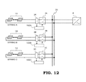
- FIG. 12 is a circuit diagram showing another schematic configuration of DC power generation system according to EMBODIMENT 1 of this invention.
- FIG. 13 is a circuit diagram showing another schematic configuration of DC power generation system according to EMBODIMENT 1 of this invention.
- FIG. 14 is a circuit diagram showing a schematic configuration of DC power generation system according to EMBODIMENT 2 of this invention.
- FIG. 15 is a schematic drawing for describing a state when a series arc occurs in a string in a DC power generation system according to EMBODIMENT 2 of this invention.
- FIG. 16 is a schematic drawing for describing a state when a series arc occurs outside a string in a DC power generation system according to EMBODIMENT 2 of this invention.
- FIG. 17 is a schematic drawing for describing a state when a parallel arc occurs in a string in a DC power generation system according to EMBODIMENT 2 of this invention.
- FIG. 18 is a drawing for describing variation of voltage-current when a parallel arc occurs in a string in a DC power generation system according to EMBODIMENT 2 of this invention.
- FIG. 19 is a schematic drawing for describing a state when a parallel arc occurs outside a string in a DC power generation system according to EMBODIMENT 2 of this invention.
- FIG. 20 is a circuit diagram showing a schematic configuration of DC power generation system according to EMBODIMENT 3 of this invention.
- FIG. 21 is a circuit diagram showing a schematic configuration of DC power generation system according to EMBODIMENT 4 of this invention.
- FIG. 1 is a circuit diagram showing a schematic configuration of a DC power generation system according to EMBODIMENT 1 of this invention.
- a string A comprises a plurality of DC power generation modules 1 A which are connected in series and the string A is connected to a DC bus 20 via a switch 2 A.
- a string B comprises a plurality of DC power generation modules 1 B which are connected in series
- a string C comprises a plurality of DC power generation modules 1 C which are connected in series
- the string B and the string C are connected to the DC bus 20 via a switch 2 B or 2 C, respectively.
- a mega solar system in many cases, many pieces of the above-mentioned strings are provided, however, in FIG.
- a voltage-current sensor 3 ( 3 A, 3 B, 3 C . . . ) is arranged, an arc detector 100 ( 100 A, 100 B, 100 C . . . ) which detects an arc by inputting an output of the voltage-current sensor 3 is attached to each circuit.
- DC buses further merge at a side of a power conditioner 4 .
- DC power which is generated by the DC power generation module 1 ( 1 A, 1 B, 1 C) is converted to AC power of commercial frequency by the power conditioner 4 and is applied to customers such as an ordinary home and a factory via commercial power network.
- a solar power generation system in which a solar power generation module (also refers to a solar power panel) 1 ( 1 A, 1 B, 1 C . . . ) is used as a DC power generation module 1 ( 1 A, 1 B, 1 C . . . ) will be described as an example.
- FIG. 2 is a block diagram showing the configuration of an arc detector 100 of a DC power generation system according to EMBODIMENT 1 of this invention.
- An input unit 110 comprises a voltage signal input unit 111 and a current signal input unit 112 .
- the input unit 110 fetches signal data of voltage and current which is detected by the voltage-current sensor 3 which is provided in the vicinity of the switch 2 to the arc detector 100 .
- the data which is fetched is transmitted to an arc analysis unit 120 .
- the arc analysis unit 120 comprises an arc noise analysis unit 121 and a voltage-current variation analysis unit 122 .
- the arc noise analysis unit 121 detects high frequency noise when an arc occurs and judges such that an arc occurs.
- the voltage-current variation analysis unit 122 After it is judged such that an arc occurs in the arc noise analysis unit 121 , in the voltage-current variation analysis unit 122 , processing of specifying an arc occurrence point and an arc mode is performed. In the voltage-current variation analysis unit 122 , it is judged whether an arc occurrence point is between solar panels and the voltage-current sensor 3 , or between the voltage-current sensor 3 and the power conditioner 4 . Further, it is judged whether a mode of an arc is a series arc or a parallel arc. When an arc occurs, a switch control unit 130 gives a command to trip only an appropriate switch 2 so as to continue operation in a sound section.
- FIG. 3 is a flow chart for describing an operation of an arc detector 100 of a DC power generation system according to EMBODIMENT 1 of this invention.
- the arc detector 100 when a voltage-current signal which is inputted from the input unit 110 is updated (Step S 1 ), an arc noise analysis (Step S 2 ) is performed in the arc noise analysis unit 121 . Based on a result of the arc noise analysis, occurrence of an arc in a DC power generation system is judged (Step S 3 ). Step 2 and Step 3 will be referred as an arc detection step.
- Step 4 When it is judged such that an arc occurs (Step 4 ), in the voltage-current variation analysis unit 122 , voltage-current before an arc occurs and voltage-current after an arc occurs is analyzed (Step 6 ). In a case where it is judged such that an arc does not occur (Step S 5 ), an operation will be returned to the beginning.
- the voltage-current variation analysis unit 122 signal data of voltage and current for a predetermined period of time is stored, and in a case where it is judged such that an arc occurs, a variation pattern of voltage and current before and after an arc occurs is analyzed, and an arc occurrence point and an arc mode are determined.
- Step 7 Whether an arc occurrence point is between a voltage-current sensor and solar panels or not is judged. Step 6 and Step 7 will be referred to as a step for specifying an arc occurrence point. After a step for specifying an arc occurrence point is performed, it is judged whether an arc mode is series arc or not (Step 8 , Step 9 ). Further, after a step for specifying an arc occurrence point is performed, in a switch control step which controls a switch, a switch is controlled.
- a DC arc comprises a series arc and a parallel arc.
- a series arc will be described.
- a series arc is an arc which occurs between solar panels, between a solar panel and a switch, between a switch and a power conditioner or between edges of damaged electric wire.
- a series arc occurs when a cable deteriorates, an execution error or lose screw, etc. occurs.
- a parallel arc occurs in a case where unexpected current flows between two conductors whose polarities are different.
- the electric wire is deteriorated or the electric wire is damaged by exterior power, a parallel arc occurs, an insulator or a protection function might be lacked and when metal parts whose polarities are different are contacted, an arc occurs.
- FIG. 4 is a schematic drawing for describing a state when a series arc 6 A occurs between solar panels 1 A and a voltage-current sensor 3 A.
- a series arc which is similar to the series arc 6 A may occur on a circuit between solar panels 1 B and a voltage-current sensor 3 B, or between solar panels 1 C and a voltage-current sensor 3 C.
- circuits are symmetry, therefore a case in which the series arc 6 A occurs between the solar panels 1 A and the voltage-current sensor 3 A will be described as an example.
- arc noise having a range from 1 kHz to 1 MHz occurs.
- Arc noise has a characteristic of 1/f, and minute noise is imposed on whole of a circuit of solar power generation system.
- noise strength when an arc does not occur, especially in a range from 1 kHz to 100 kHz, there is specific difference, therefore, as arc noise which is imposed on a current, by detecting high frequency noise in a range at least from 1 kHz to 100 kHz, occurrence of an arc can be judged.
- Propagation of arc noise is well-known. By cancelling noise from a power conditioner, occurrence of an arc can be easily detected.
- this patent proposes an arc judgement method in which an arc occurrence point and an arc mode can be specified not only by arc noise but also by analyzing voltage-current variation characteristic.
- FIG. 5 shows a voltage-current variation characteristic when a series arc occurs at a point shown in the schematic drawing of FIG. 4 .
- a voltage-current characteristic of solar power generation depends on solar irradiance. The larger solar irradiance is, the more maximum operation output current Ipm increases, and the smaller solar irradiance is, the smaller maximum operation output current Ipm is. Further, regardless of solar irradiance, maximum operation output voltage Vpm does not greatly variate.
- an operation point 11 which is maximum power is continued at all times. As a result, an output of maximum operation output voltage Vpm and maximum operation output current Ipm is an operation point at normal time.
- a decreasing amount of voltage depends on arc voltage, and arc voltage depends on maximum operation current.
- circuit impedance increases and a current decreases.
- Voltage of a voltage-current sensor 3 B and 3 C of a string in which a series arc does not occur decreases, current increases and an operation point is an operation point 13 .
- Voltage-current of a string in which a series arc does not occur operates on the voltage-current characteristic curve 10 of a solar power generation, therefore current increases in accompany with decrease of voltage.
- FIG. 7 shows a voltage-current variation characteristic when a series arc occurs at a point shown in a schematic drawing of FIG. 6 .
- a series arc 6 B occurs between a voltage-current sensor 3 A and a power conditioner 4 .
- voltage of the voltage-current sensor 3 A increases and current of the voltage-current sensor 3 A decreases.
- an operation point is an operation point 14 after an arc occurs. This is because such that circuit impedance increases and current decreases due to occurrence of an arc.
- the operation point 14 is an operation point on the voltage-current characteristic curve 10 of normal operation.
- voltage-current sensor 3 B of a string B and a voltage-current sensor 3 C of a string C voltage increases and current decreases.
- the operation point 14 of the string B and the string C after an arc occurs coincides with an operation point of the string A after an arc occurs.
- circuits are symmetry, variation amount of voltage and that of current are same.
- FIG. 9 shows a voltage-current variation characteristic when a parallel arc 7 A occurs at a point shown in a schematic drawing of FIG. 8 .
- a parallel arc 7 occurs between solar panels 1 A and a voltage-current sensor 3 A
- voltage and current of the voltage-current sensor 3 A decreases and an operation point is an operation point 15 after an arc occurs.
- Voltage of the operation point 15 is nearly arc voltage (10V to 40V), and current flows backward from other strings, therefore, excessive current flows backward.
- the operation point 15 is an operation point which greatly deviates from the voltage-current characteristic curve 10 of normal operation.
- FIG. 11 shows a voltage-current variation characteristic when a parallel arc 7 B occurs at a point shown in a schematic drawing of FIG. 10 .
- a parallel arc 7 B occurs between a voltage-current sensor 3 A and a power conditioner 4
- voltage of the voltage-current sensor 3 A decreases
- current of the voltage-current sensor 3 A increases
- an operation point is an operation point 19 after an arc occurs.
- Voltage of the operation point 19 is nearly arc voltage (10V to 40V)
- a value of current is close to that of short circuit current Isc based on the voltage-current characteristic curve 10 .
- an abnormality is not caused in strings. Therefore, an operation point 16 is an operation point on the voltage-current characteristic curve 10 of normal operation. Operation points of other strings coincide with an operation point 19 .
- circuits are symmetry, variation amount of voltage and that of a current are same.
- An operation of a switch control unit 130 that is, an operation of a switch control step will be determined after an arc occurrence point is judged.
- an arc detector 100 A of the string A to which a signal of a sensor which shows a variation of voltage-current of an operation point 12 after an arc shown in FIG. 5 occurs trips a switch 2 A in the vicinity of a voltage-current sensor 3 A.
- current flowing from a solar power generation stops so as to extinguish a series arc.
- the switch 2 A is tripped, an operation point of a string B and that of a string C are returned from an operation point 13 to an operation point 11 , and an operation of the DC generation system can be continued by the string B and the string C.
- an arc detector 100 A to which a signal of a sensor which shows a variation of voltage-current of an operation point 15 after an arc occurs shown in FIG. 9 trips the switch 2 A in the vicinity of the voltage-current sensor 3 A.
- a voltage-current operation point before and after an arc occurs is analyzed, when a voltage-current operation point, after an arc occurs, deviates from a voltage-current characteristic curve of normal operation, it is judged such that an arc occurs in the own string, and the own switch 2 provided in the own string is tripped.
- This patent includes an application to a solar power generation system at which a backflow prevention diode 5 ( 5 A, 5 B, 5 C . . . ) as shown in FIG. 14 is provided.
- a backflow prevention diode 5 there are two cases, that is, a case in which the backflow prevention diode 5 is provided in a direction of a current which flows from solar power panels 1 to a power conditioner 4 , to a cable which is provided at a positive electrode side, and a case in which the backflow prevention diode 5 is provided in a direction of a current which flows from the power conditioner 4 to a side of the solar panels 1 , to a cable which is provided at a negative electrode side.
- a case in which the backflow prevention diode 5 is provided at a cable which is provided at a positive electrode side will be described as an example.
- the backflow prevention diode 5 ( 5 A, 5 B, 5 C . . . ) is provided and a series arc occurs between a voltage-current sensor 3 A and solar power panels 1 A
- a voltage-current variation characteristic is same as that shown in FIG. 5 .
- a series arc 6 A occurs between the solar power panels 1 A and the voltage-current sensor 3 A
- voltage and current of the voltage-current sensor 3 A decreases and an operation point is an operation point 12 after an arc occurs.
- a voltage-current variation characteristic is same as that shown in FIG. 7 .
- voltage of a voltage-current sensor 3 A, 3 B and 3 C of each string increases and current decreases.
- an operation point is an operation point 14 .
- FIG. 18 a voltage-current variation characteristic will be shown in FIG. 18 .
- a parallel arc 7 A occurs between the solar power panels 1 A and the voltage-current sensor 3 A in a solar power generation system to which a backflow prevention diode is connected, voltage and current of the voltage-current sensor 3 A decreases and an operation point is an operation point 17 after an arc occurs.
- Voltage of the operation point 17 is nearly arc voltage (10V to 40V), and current is not outputted from the solar power panels 1 A and a backward flow from other strings is prevented by a backflow prevention diode. As a result, current is 0.
- voltage of the voltage-current sensor 3 B and 3 C of other strings decreases and current increases, and an operation point is an operation point 18 of other circuit after an arc occurs.
- Voltage of the operation point 18 is nearly arc voltage (10V to 40V), and current is an equal value of a short circuit current value.
- a voltage-current variation characteristic is same as that shown in FIG. 11 .
- Voltage of the voltage-current sensor 3 A decreases and current increases and an operation point is an operation point 19 after an arc occurs.
- Voltage of the operation point 19 is nearly arc voltage (10V to 40V), and a value of current is close to a value of a short circuit current Isc based on the voltage-current characteristic curve 10 .
- An operation point of the string B and the string C after an arc occurs coincides with the operation point 19 of the string A.
- an operation of a switch control unit 130 is same as that of a switch operation command in a case of FIG. 4 , FIG. 6 and FIG. 10 .
- an arc detector to which a signal of a sensor which indicates a voltage-current variation of an operation point after an arc occurs 18 is inputted, trips a switch 2 A in the vicinity of the voltage-current sensor 3 A.
- FIG. 20 is a schematic circuit diagram showing the configuration of DC power generation system according to EMBODIMENT 3 of this invention.
- EMBODIMENT 1 and EMBODIMENT 2 it is configured such that an arc detector 100 which is provided at each string judges whether to trip a switch 2 of the own string or not.
- EMBODIMENT 3 it is configured such that data which is transmitted from a voltage-current sensor 3 ( 3 A, 3 B . . . ) which is provided at each string is analyzed by one arc detector 200 so as to judge an arc occurrence point and an arc mode, and output an appropriate switch operation command.
- an operation point in the voltage-current sensor 3 A of the string A is an operation point 15 shown in FIG. 9 and an operation point of a voltage-current sensor 3 B of a string B and an operation point of a voltage-current sensor 3 C of a string C is an operation point 16 shown in FIG. 9 .
- an operation point in the voltage-current sensor 3 of each string is an operation point 19 shown in FIG. 11 .
- EMBODIMENT 1 and EMBODIMENT 2 occurrence of an arc is judged separately at each string, therefore, at a string B and a string C, it is difficult to judge whether a parallel arc occurs in the string A or a parallel arc occurs at the DC bus 20 or at a side which is closer to the power conditioner 4 than the DC bus 20 . Consequently, in EMBODIMENT 1, in a case where it is judged such that an arc occurs outside the own string, when an operation point is continued for a predetermined period of time, it is configured such that a switch is tripped so as to separate the own string.
- EMBODIMENT 3 As shown in FIG. 20 , when signals from a voltage-current sensors 3 ( 3 A, 3 B . . . ) of all strings are inputted and judged comprehensively by an arc detector 200 , an arc occurrence point can be appropriately judged. That is, as shown in FIG. 9 , in a case where an operation point in the string A is an operation point 15 and an operation point of other string is an operation point 16 , it can be judged such that a parallel arc 7 occurs in the string A, and in this case, only a switch 2 A is tripped. On the other hand, as shown in FIG.
- FIG. 21 is a schematic circuit diagram showing the configuration of DC power generation system according to EMBODIMENT 4 of this invention.
- an arc detector 100 100 A, 100 B . . . ) which is provided at each string judges whether an arc occurs in the own string or not and a result of judgement is transmitted to an arc occurrence point specifying device 201 .
- Signals from all of arc detectors 100 100 A, 100 B . . . ) are inputted in the arc occurrence point specifying device 201 and judged comprehensively so as to specify an arc occurrence point.
- the arc occurrence point specifying device 201 judges such that a parallel arc 7 B occurs at a DC bus 20 or at a side which is closer to a power conditioner 4 than the DC bus 20 , a command is transmitted to all of arc detectors 100 so as to trip switches 2 ( 2 A, 2 B . . . ) of all strings.
- the arc occurrence point specifying device 201 transmits a command not to trip switches other than a switch of the string A to arc detectors or switches of strings other than the string A. In a case of a series arc, similar procedure is performed.
- an arc detector which judges such that an arc occurs in the own string, immediately trips the own switch.
- an arc detector which judges such that an arc occurs outside the own string, trips the own switch when a signal from the arc occurrence specifying device 201 is received.
Landscapes
- Engineering & Computer Science (AREA)
- Power Engineering (AREA)
- Photovoltaic Devices (AREA)
- Locating Faults (AREA)
Applications Claiming Priority (3)
| Application Number | Priority Date | Filing Date | Title |
|---|---|---|---|
| JP2013-174105 | 2013-08-26 | ||
| JP2013174105 | 2013-08-26 | ||
| PCT/JP2014/050748 WO2015029458A1 (ja) | 2013-08-26 | 2014-01-17 | 直流発電システムおよび直流発電システムの保護方法 |
Publications (2)
| Publication Number | Publication Date |
|---|---|
| US20160181799A1 US20160181799A1 (en) | 2016-06-23 |
| US9866017B2 true US9866017B2 (en) | 2018-01-09 |
Family
ID=52586045
Family Applications (1)
| Application Number | Title | Priority Date | Filing Date |
|---|---|---|---|
| US14/911,238 Active 2034-08-18 US9866017B2 (en) | 2013-08-26 | 2014-01-17 | DC power generation system and protection method for DC power generation system |
Country Status (5)
| Country | Link |
|---|---|
| US (1) | US9866017B2 (de) |
| EP (1) | EP3041104B1 (de) |
| JP (1) | JP6132919B2 (de) |
| CN (1) | CN105474494B (de) |
| WO (1) | WO2015029458A1 (de) |
Cited By (1)
| Publication number | Priority date | Publication date | Assignee | Title |
|---|---|---|---|---|
| EP4580046A1 (de) * | 2023-12-26 | 2025-07-02 | Sungrow Power Supply Co., Ltd. | Verfahren zur lichtbogenerkennung, wechselrichter und fotovoltaisches system |
Families Citing this family (32)
| Publication number | Priority date | Publication date | Assignee | Title |
|---|---|---|---|---|
| FR2977677B1 (fr) | 2011-07-04 | 2013-08-23 | Commissariat Energie Atomique | Detection d'arcs electriques dans les installations photovoltaiques |
| JP2015523847A (ja) * | 2012-07-09 | 2015-08-13 | ソーラーボス、インク. | 太陽電池パネルにおける逆電流障害の防止 |
| FR3010261B1 (fr) * | 2013-08-29 | 2015-10-02 | Commissariat Energie Atomique | Detection d'un arc electrique en parallele sur les bornes principales d'une installation photovoltaique |
| FR3010260B1 (fr) | 2013-08-29 | 2015-10-02 | Commissariat Energie Atomique | Detection d'arcs electriques dans les installations photovoltaiques |
| JP6246062B2 (ja) * | 2014-04-30 | 2017-12-13 | 三菱電機株式会社 | 直流発電システムおよび直流発電システムの保護方法 |
| FR3044489B1 (fr) * | 2015-12-01 | 2017-12-22 | Commissariat Energie Atomique | Procede et dispositif de detection d'un arc electrique parasite dans une installation photovoltaique |
| JP6597394B2 (ja) * | 2016-02-29 | 2019-10-30 | オムロン株式会社 | アーク発生位置検出装置およびアーク発生位置検出方法 |
| CN109417285B (zh) * | 2016-06-21 | 2020-11-06 | 三菱电机株式会社 | 直流电气回路保护装置及电弧检测方法 |
| JP6234647B1 (ja) | 2016-06-21 | 2017-11-22 | 三菱電機株式会社 | 直流電気回路保護装置およびアーク検出方法 |
| JP2018028498A (ja) * | 2016-08-19 | 2018-02-22 | 富士電機機器制御株式会社 | アーク故障検出システム |
| WO2018046654A1 (de) * | 2016-09-12 | 2018-03-15 | Phoenix Contact Gmbh & Co. Kg | Photovoltaik-anlage, schutzschaltung und verfahren zum selbstständigen abschalten eines photovoltaik-strangs |
| LU93202B1 (de) * | 2016-09-12 | 2018-04-05 | Phoenix Contact Gmbh & Co Kg Intellectual Property Licenses & Standards | Multistrang-Photovoltaik-Anlage, Verfahren zum Betrieb einer solchen und Rückstromschutzschaltung für eine solche |
| JP6834334B2 (ja) * | 2016-10-17 | 2021-02-24 | 富士電機機器制御株式会社 | アーク故障検出システム |
| JP6834458B2 (ja) * | 2016-12-20 | 2021-02-24 | 富士電機機器制御株式会社 | アーク故障検出システム |
| US11418018B2 (en) * | 2017-02-14 | 2022-08-16 | Panasonic Intellectual Property Management Co., Ltd. | Arc detection circuit, switch system, power conditioner system and arc detection method |
| JP6807552B2 (ja) * | 2017-02-14 | 2021-01-06 | パナソニックIpマネジメント株式会社 | アーク検出回路、開閉器システム、パワーコンディショナシステム及びアーク検出方法 |
| JP2020012727A (ja) * | 2018-07-18 | 2020-01-23 | 日本電信電話株式会社 | 回線確認装置および回線確認方法 |
| CN110095702A (zh) * | 2019-05-22 | 2019-08-06 | 安徽升隆电气有限公司 | 一种电弧性能分析仪器 |
| JP7370666B2 (ja) * | 2019-11-01 | 2023-10-30 | 日東工業株式会社 | 放電検出システム |
| CN110618366A (zh) * | 2019-11-05 | 2019-12-27 | 阳光电源股份有限公司 | 一种直流电弧检测方法及装置 |
| KR102341332B1 (ko) * | 2019-12-03 | 2021-12-21 | 한국에너지기술연구원 | 에너지원의 출력경로에서 아크를 검출하는 장치 |
| CN115552755A (zh) * | 2020-06-01 | 2022-12-30 | 华为数字能源技术有限公司 | 一种故障保护装置 |
| CN111817586B (zh) * | 2020-07-07 | 2021-05-04 | 武汉理工大学 | 一种矿井直流架线用整流电源装置及其架线短路检测方法 |
| CN111983402A (zh) * | 2020-08-20 | 2020-11-24 | 阳光电源股份有限公司 | 一种直流电弧故障检测方法及光伏逆变系统 |
| EP4206714A4 (de) | 2020-08-26 | 2024-03-13 | Panasonic Intellectual Property Management Co., Ltd. | Lichtbogenerkennungsvorrichtung, lichtbogenerkennungssystem, lichtbogenerkennungsverfahren und programm |
| CA3192723A1 (en) * | 2020-09-25 | 2022-03-31 | Patrick L. Chapman | High-power microinverter and system |
| CN112468086B (zh) * | 2020-11-13 | 2022-01-25 | 丰郅(上海)新能源科技有限公司 | 应用于光伏能源的电弧监测系统及电弧监测方法 |
| CN112462176B (zh) * | 2020-11-13 | 2022-06-28 | 丰郅(上海)新能源科技有限公司 | 支持检测光伏系统直流电弧故障的装置及方法 |
| CN119341383A (zh) * | 2021-09-09 | 2025-01-21 | 华为数字能源技术有限公司 | 一种光伏系统、逆变器及直流电弧检测的方法 |
| CN113782400A (zh) * | 2021-09-10 | 2021-12-10 | 柳州铁道职业技术学院 | 一种新能源汽车动力电池直流高压防逆电反流保险管 |
| CN114744597A (zh) * | 2022-03-21 | 2022-07-12 | 锦浪科技股份有限公司 | 一种具备电弧检测功能的直流分断装置及其控制方法 |
| DE102024208142A1 (de) * | 2024-08-27 | 2026-03-05 | Siemens Aktiengesellschaft | Photovoltaikumrichter mit selektiver Abschaltung bei Auftreten eines Lichtbogenereignisses und eine Photovoltaikanordnung mit einem solchen Photovoltaikumrichter |
Citations (8)
| Publication number | Priority date | Publication date | Assignee | Title |
|---|---|---|---|---|
| WO2002039561A2 (en) | 2000-11-13 | 2002-05-16 | Eaton Corporation | Detection of arcing in dc electrical systems |
| US20040027749A1 (en) | 2001-11-09 | 2004-02-12 | Zuercher Joseph C. | Detection of arcing in dc electrical systems |
| US20110090607A1 (en) | 2009-10-20 | 2011-04-21 | Luebke Charles J | String and system employing direct current electrical generating modules and a number of string protectors |
| US20120112760A1 (en) | 2010-11-09 | 2012-05-10 | Solaredge Technologies Ltd. | Arc Detection and Prevention in a Power Generation System |
| US8179147B2 (en) * | 2009-07-23 | 2012-05-15 | Enphase Energy, Inc. | Method and apparatus for detection and control of dc arc faults |
| US20120134058A1 (en) | 2009-08-14 | 2012-05-31 | Fronius International Gmbh | Method for detecting arcs in photovoltaic systems and such a photovoltaic system |
| US8218274B2 (en) * | 2009-12-15 | 2012-07-10 | Eaton Corporation | Direct current arc fault circuit interrupter, direct current arc fault detector, noise blanking circuit for a direct current arc fault circuit interrupter, and method of detecting arc faults |
| US9768605B2 (en) * | 2014-12-29 | 2017-09-19 | Eaton Corporation | Arc fault detection system and method and circuit interrupter employing same |
Family Cites Families (11)
| Publication number | Priority date | Publication date | Assignee | Title |
|---|---|---|---|---|
| US6984987B2 (en) * | 2003-06-12 | 2006-01-10 | Sharper Image Corporation | Electro-kinetic air transporter and conditioner devices with enhanced arching detection and suppression features |
| CN1696723A (zh) * | 2004-05-14 | 2005-11-16 | 人间电气技术株式会社 | 电弧故障检测设备 |
| US20070279068A1 (en) * | 2006-05-31 | 2007-12-06 | Harres Daniel N | Power diagnostic system and method |
| US7368918B2 (en) * | 2006-07-27 | 2008-05-06 | Siemens Energy & Automation | Devices, systems, and methods for adaptive RF sensing in arc fault detection |
| CN101308108B (zh) * | 2007-05-15 | 2011-06-29 | 清华大学 | 一种包含一维纳米材料敏感元件的传感器的制备方法 |
| US8179145B2 (en) * | 2008-01-24 | 2012-05-15 | Siemens Industry, Inc. | Method and apparatus for testing AFCI device for series arc detection |
| JP5419579B2 (ja) * | 2009-05-28 | 2014-02-19 | 京セラ株式会社 | アーク検出手段とそれを用いた制御手段及び連絡手段 |
| KR20120032925A (ko) * | 2010-09-29 | 2012-04-06 | 삼성전자주식회사 | 전기기기, 전기기기 시스템 및 그 아크 결함 검출 방법 |
| CN102288857B (zh) * | 2011-05-18 | 2013-06-19 | 浙江科技学院 | 一种故障电弧的辨识检测方法及其检测保护装置 |
| JP5888972B2 (ja) * | 2011-12-22 | 2016-03-22 | 三菱電機株式会社 | 太陽光発電システム |
| DE102012104314B4 (de) * | 2012-05-18 | 2014-04-10 | Sma Solar Technology Ag | Verfahren und Vorrichtung zum Lokalisieren und Löschen eines Lichtbogens |
-
2014
- 2014-01-17 WO PCT/JP2014/050748 patent/WO2015029458A1/ja not_active Ceased
- 2014-01-17 EP EP14840613.5A patent/EP3041104B1/de active Active
- 2014-01-17 CN CN201480046617.5A patent/CN105474494B/zh active Active
- 2014-01-17 US US14/911,238 patent/US9866017B2/en active Active
- 2014-01-17 JP JP2015534010A patent/JP6132919B2/ja active Active
Patent Citations (11)
| Publication number | Priority date | Publication date | Assignee | Title |
|---|---|---|---|---|
| WO2002039561A2 (en) | 2000-11-13 | 2002-05-16 | Eaton Corporation | Detection of arcing in dc electrical systems |
| US20040027749A1 (en) | 2001-11-09 | 2004-02-12 | Zuercher Joseph C. | Detection of arcing in dc electrical systems |
| US8179147B2 (en) * | 2009-07-23 | 2012-05-15 | Enphase Energy, Inc. | Method and apparatus for detection and control of dc arc faults |
| US20120134058A1 (en) | 2009-08-14 | 2012-05-31 | Fronius International Gmbh | Method for detecting arcs in photovoltaic systems and such a photovoltaic system |
| US20110090607A1 (en) | 2009-10-20 | 2011-04-21 | Luebke Charles J | String and system employing direct current electrical generating modules and a number of string protectors |
| JP2011091995A (ja) | 2009-10-20 | 2011-05-06 | Eaton Corp | 直流発電モジュール及び多数のストリング保護装置を用いるストリング及びシステム |
| US8218274B2 (en) * | 2009-12-15 | 2012-07-10 | Eaton Corporation | Direct current arc fault circuit interrupter, direct current arc fault detector, noise blanking circuit for a direct current arc fault circuit interrupter, and method of detecting arc faults |
| US20120112760A1 (en) | 2010-11-09 | 2012-05-10 | Solaredge Technologies Ltd. | Arc Detection and Prevention in a Power Generation System |
| GB2485527A (en) | 2010-11-09 | 2012-05-23 | Solaredge Technologies Ltd | Arc detection in a system including a photovoltaic panel |
| JP2012112937A (ja) | 2010-11-09 | 2012-06-14 | Solaredge Technologies Ltd | 発電システムのアーク検出および防止 |
| US9768605B2 (en) * | 2014-12-29 | 2017-09-19 | Eaton Corporation | Arc fault detection system and method and circuit interrupter employing same |
Non-Patent Citations (2)
| Title |
|---|
| Extended European Search Report dated May 8, 2017 in Patent Application No. 14840613.5. |
| International Search Report dated Apr. 8, 2014, in PCT/JP2014/050748 Filed Jan. 17, 2014. |
Cited By (1)
| Publication number | Priority date | Publication date | Assignee | Title |
|---|---|---|---|---|
| EP4580046A1 (de) * | 2023-12-26 | 2025-07-02 | Sungrow Power Supply Co., Ltd. | Verfahren zur lichtbogenerkennung, wechselrichter und fotovoltaisches system |
Also Published As
| Publication number | Publication date |
|---|---|
| WO2015029458A1 (ja) | 2015-03-05 |
| CN105474494B (zh) | 2017-10-03 |
| CN105474494A (zh) | 2016-04-06 |
| EP3041104B1 (de) | 2021-06-02 |
| JP6132919B2 (ja) | 2017-05-24 |
| US20160181799A1 (en) | 2016-06-23 |
| JPWO2015029458A1 (ja) | 2017-03-02 |
| EP3041104A1 (de) | 2016-07-06 |
| EP3041104A4 (de) | 2017-06-07 |
Similar Documents
| Publication | Publication Date | Title |
|---|---|---|
| US9866017B2 (en) | DC power generation system and protection method for DC power generation system | |
| JP6246062B2 (ja) | 直流発電システムおよび直流発電システムの保護方法 | |
| US9995796B1 (en) | Identifying an arc-fault type in photovoltaic arrays | |
| EP2681821B1 (de) | Verfahren und vorrichtung zur detektion eines lichtbogenfehlers in einer stromversorgung | |
| US8837097B2 (en) | Protection, monitoring or indication apparatus for a direct current electrical generating apparatus or a plurality of strings | |
| US20150381111A1 (en) | Arc fault detection and extinguishing | |
| US20170317500A1 (en) | System and method of sensing and isolating a ground fault in a dc-to-ac power conversion system | |
| CN105445611B (zh) | 故障电弧的检测方法和检测装置 | |
| US9148086B2 (en) | Photovoltaic DC sub-array control system and method | |
| JP5888972B2 (ja) | 太陽光発電システム | |
| AU2014224084B2 (en) | Electrical control and protection device | |
| US8587906B2 (en) | Photovotaic system including hybrid bi-directional DC contactors and method of detection and isolation of faults therein | |
| US20150338472A1 (en) | Method And Device For Detection Of A Fault In A Protected Unit | |
| US9391441B2 (en) | Zone selective interlocking for optical flash detection suppression | |
| EP2580828A1 (de) | Fehlerschutz für hvdc-übertragungsleitungen | |
| CN103733457A (zh) | 用于电弧减轻系统的自适应光检测 | |
| JP6597394B2 (ja) | アーク発生位置検出装置およびアーク発生位置検出方法 | |
| JP2018028498A (ja) | アーク故障検出システム | |
| CN115663769B (zh) | 光伏发电系统直流并联电弧保护及定位系统和方法 | |
| JP2014042364A (ja) | 太陽光発電システムおよびアーク検出保護装置 | |
| KR101881411B1 (ko) | 태양광 발전 및 태양광발전 에너지 저장 시스템, 그리고 태양광 발전 및 태양광발전 에너지 저장 시스템에서의 아크 검출 및 차단방법 | |
| EP3391489B1 (de) | Erdschlussdetektions- und schutzschaltungssystem | |
| KR101879742B1 (ko) | 아크 종류와 위치 검출 및 열화 방지 기능을 구비한 태양광 발전 시스템 | |
| KR102175998B1 (ko) | 전력용 반도체형 한류기를 이용한 멀티 터미널 직류 배전계통의 보호 방법, 장치 및 시스템 | |
| CN102694367A (zh) | 太阳能电池模块用配线电缆 |
Legal Events
| Date | Code | Title | Description |
|---|---|---|---|
| AS | Assignment |
Owner name: MITSUBISHI ELECTRIC CORPORATION, JAPAN Free format text: ASSIGNMENT OF ASSIGNORS INTEREST;ASSIGNORS:KANEMARU, MAKOTO;SHINDOI, TAKESHI;YANO, TOMOTAKA;SIGNING DATES FROM 20151109 TO 20151112;REEL/FRAME:037695/0947 |
|
| STCF | Information on status: patent grant |
Free format text: PATENTED CASE |
|
| MAFP | Maintenance fee payment |
Free format text: PAYMENT OF MAINTENANCE FEE, 4TH YEAR, LARGE ENTITY (ORIGINAL EVENT CODE: M1551); ENTITY STATUS OF PATENT OWNER: LARGE ENTITY Year of fee payment: 4 |
|
| MAFP | Maintenance fee payment |
Free format text: PAYMENT OF MAINTENANCE FEE, 8TH YEAR, LARGE ENTITY (ORIGINAL EVENT CODE: M1552); ENTITY STATUS OF PATENT OWNER: LARGE ENTITY Year of fee payment: 8 |