US9863582B2 - Gas tank container - Google Patents
Gas tank container Download PDFInfo
- Publication number
- US9863582B2 US9863582B2 US14/078,872 US201314078872A US9863582B2 US 9863582 B2 US9863582 B2 US 9863582B2 US 201314078872 A US201314078872 A US 201314078872A US 9863582 B2 US9863582 B2 US 9863582B2
- Authority
- US
- United States
- Prior art keywords
- gas tank
- tank container
- vessel
- gas
- feet
- Prior art date
- Legal status (The legal status is an assumption and is not a legal conclusion. Google has not performed a legal analysis and makes no representation as to the accuracy of the status listed.)
- Active, expires
Links
- 239000007788 liquid Substances 0.000 abstract description 5
- 239000007789 gas Substances 0.000 description 53
- 239000002131 composite material Substances 0.000 description 1
- 238000010276 construction Methods 0.000 description 1
- 238000009434 installation Methods 0.000 description 1
- 238000012986 modification Methods 0.000 description 1
- 230000004048 modification Effects 0.000 description 1
Images


Classifications
-
- F—MECHANICAL ENGINEERING; LIGHTING; HEATING; WEAPONS; BLASTING
- F17—STORING OR DISTRIBUTING GASES OR LIQUIDS
- F17C—VESSELS FOR CONTAINING OR STORING COMPRESSED, LIQUEFIED OR SOLIDIFIED GASES; FIXED-CAPACITY GAS-HOLDERS; FILLING VESSELS WITH, OR DISCHARGING FROM VESSELS, COMPRESSED, LIQUEFIED, OR SOLIDIFIED GASES
- F17C13/00—Details of vessels or of the filling or discharging of vessels
- F17C13/04—Arrangement or mounting of valves
-
- F—MECHANICAL ENGINEERING; LIGHTING; HEATING; WEAPONS; BLASTING
- F17—STORING OR DISTRIBUTING GASES OR LIQUIDS
- F17C—VESSELS FOR CONTAINING OR STORING COMPRESSED, LIQUEFIED OR SOLIDIFIED GASES; FIXED-CAPACITY GAS-HOLDERS; FILLING VESSELS WITH, OR DISCHARGING FROM VESSELS, COMPRESSED, LIQUEFIED, OR SOLIDIFIED GASES
- F17C13/00—Details of vessels or of the filling or discharging of vessels
- F17C13/08—Mounting arrangements for vessels
- F17C13/083—Mounting arrangements for vessels for medium-sized mobile storage vessels, e.g. tank vehicles or railway tank vehicles
-
- F—MECHANICAL ENGINEERING; LIGHTING; HEATING; WEAPONS; BLASTING
- F17—STORING OR DISTRIBUTING GASES OR LIQUIDS
- F17C—VESSELS FOR CONTAINING OR STORING COMPRESSED, LIQUEFIED OR SOLIDIFIED GASES; FIXED-CAPACITY GAS-HOLDERS; FILLING VESSELS WITH, OR DISCHARGING FROM VESSELS, COMPRESSED, LIQUEFIED, OR SOLIDIFIED GASES
- F17C2201/00—Vessel construction, in particular geometry, arrangement or size
- F17C2201/01—Shape
- F17C2201/0104—Shape cylindrical
- F17C2201/0109—Shape cylindrical with exteriorly curved end-piece
-
- F—MECHANICAL ENGINEERING; LIGHTING; HEATING; WEAPONS; BLASTING
- F17—STORING OR DISTRIBUTING GASES OR LIQUIDS
- F17C—VESSELS FOR CONTAINING OR STORING COMPRESSED, LIQUEFIED OR SOLIDIFIED GASES; FIXED-CAPACITY GAS-HOLDERS; FILLING VESSELS WITH, OR DISCHARGING FROM VESSELS, COMPRESSED, LIQUEFIED, OR SOLIDIFIED GASES
- F17C2201/00—Vessel construction, in particular geometry, arrangement or size
- F17C2201/03—Orientation
- F17C2201/035—Orientation with substantially horizontal main axis
-
- F—MECHANICAL ENGINEERING; LIGHTING; HEATING; WEAPONS; BLASTING
- F17—STORING OR DISTRIBUTING GASES OR LIQUIDS
- F17C—VESSELS FOR CONTAINING OR STORING COMPRESSED, LIQUEFIED OR SOLIDIFIED GASES; FIXED-CAPACITY GAS-HOLDERS; FILLING VESSELS WITH, OR DISCHARGING FROM VESSELS, COMPRESSED, LIQUEFIED, OR SOLIDIFIED GASES
- F17C2201/00—Vessel construction, in particular geometry, arrangement or size
- F17C2201/05—Size
- F17C2201/054—Size medium (>1 m3)
-
- F—MECHANICAL ENGINEERING; LIGHTING; HEATING; WEAPONS; BLASTING
- F17—STORING OR DISTRIBUTING GASES OR LIQUIDS
- F17C—VESSELS FOR CONTAINING OR STORING COMPRESSED, LIQUEFIED OR SOLIDIFIED GASES; FIXED-CAPACITY GAS-HOLDERS; FILLING VESSELS WITH, OR DISCHARGING FROM VESSELS, COMPRESSED, LIQUEFIED, OR SOLIDIFIED GASES
- F17C2203/00—Vessel construction, in particular walls or details thereof
- F17C2203/06—Materials for walls or layers thereof; Properties or structures of walls or their materials
- F17C2203/0602—Wall structures; Special features thereof
- F17C2203/0612—Wall structures
- F17C2203/0614—Single wall
- F17C2203/0617—Single wall with one layer
-
- F—MECHANICAL ENGINEERING; LIGHTING; HEATING; WEAPONS; BLASTING
- F17—STORING OR DISTRIBUTING GASES OR LIQUIDS
- F17C—VESSELS FOR CONTAINING OR STORING COMPRESSED, LIQUEFIED OR SOLIDIFIED GASES; FIXED-CAPACITY GAS-HOLDERS; FILLING VESSELS WITH, OR DISCHARGING FROM VESSELS, COMPRESSED, LIQUEFIED, OR SOLIDIFIED GASES
- F17C2205/00—Vessel construction, in particular mounting arrangements, attachments or identifications means
- F17C2205/01—Mounting arrangements
- F17C2205/0103—Exterior arrangements
- F17C2205/0107—Frames
-
- F—MECHANICAL ENGINEERING; LIGHTING; HEATING; WEAPONS; BLASTING
- F17—STORING OR DISTRIBUTING GASES OR LIQUIDS
- F17C—VESSELS FOR CONTAINING OR STORING COMPRESSED, LIQUEFIED OR SOLIDIFIED GASES; FIXED-CAPACITY GAS-HOLDERS; FILLING VESSELS WITH, OR DISCHARGING FROM VESSELS, COMPRESSED, LIQUEFIED, OR SOLIDIFIED GASES
- F17C2205/00—Vessel construction, in particular mounting arrangements, attachments or identifications means
- F17C2205/01—Mounting arrangements
- F17C2205/0123—Mounting arrangements characterised by number of vessels
- F17C2205/0126—One vessel
-
- F—MECHANICAL ENGINEERING; LIGHTING; HEATING; WEAPONS; BLASTING
- F17—STORING OR DISTRIBUTING GASES OR LIQUIDS
- F17C—VESSELS FOR CONTAINING OR STORING COMPRESSED, LIQUEFIED OR SOLIDIFIED GASES; FIXED-CAPACITY GAS-HOLDERS; FILLING VESSELS WITH, OR DISCHARGING FROM VESSELS, COMPRESSED, LIQUEFIED, OR SOLIDIFIED GASES
- F17C2205/00—Vessel construction, in particular mounting arrangements, attachments or identifications means
- F17C2205/01—Mounting arrangements
- F17C2205/0153—Details of mounting arrangements
- F17C2205/0157—Details of mounting arrangements for transport
-
- F—MECHANICAL ENGINEERING; LIGHTING; HEATING; WEAPONS; BLASTING
- F17—STORING OR DISTRIBUTING GASES OR LIQUIDS
- F17C—VESSELS FOR CONTAINING OR STORING COMPRESSED, LIQUEFIED OR SOLIDIFIED GASES; FIXED-CAPACITY GAS-HOLDERS; FILLING VESSELS WITH, OR DISCHARGING FROM VESSELS, COMPRESSED, LIQUEFIED, OR SOLIDIFIED GASES
- F17C2205/00—Vessel construction, in particular mounting arrangements, attachments or identifications means
- F17C2205/01—Mounting arrangements
- F17C2205/0153—Details of mounting arrangements
- F17C2205/0188—Hanging up devices
-
- F—MECHANICAL ENGINEERING; LIGHTING; HEATING; WEAPONS; BLASTING
- F17—STORING OR DISTRIBUTING GASES OR LIQUIDS
- F17C—VESSELS FOR CONTAINING OR STORING COMPRESSED, LIQUEFIED OR SOLIDIFIED GASES; FIXED-CAPACITY GAS-HOLDERS; FILLING VESSELS WITH, OR DISCHARGING FROM VESSELS, COMPRESSED, LIQUEFIED, OR SOLIDIFIED GASES
- F17C2205/00—Vessel construction, in particular mounting arrangements, attachments or identifications means
- F17C2205/03—Fluid connections, filters, valves, closure means or other attachments
- F17C2205/0302—Fittings, valves, filters, or components in connection with the gas storage device
- F17C2205/0323—Valves
- F17C2205/0329—Valves manually actuated
-
- F—MECHANICAL ENGINEERING; LIGHTING; HEATING; WEAPONS; BLASTING
- F17—STORING OR DISTRIBUTING GASES OR LIQUIDS
- F17C—VESSELS FOR CONTAINING OR STORING COMPRESSED, LIQUEFIED OR SOLIDIFIED GASES; FIXED-CAPACITY GAS-HOLDERS; FILLING VESSELS WITH, OR DISCHARGING FROM VESSELS, COMPRESSED, LIQUEFIED, OR SOLIDIFIED GASES
- F17C2205/00—Vessel construction, in particular mounting arrangements, attachments or identifications means
- F17C2205/03—Fluid connections, filters, valves, closure means or other attachments
- F17C2205/0302—Fittings, valves, filters, or components in connection with the gas storage device
- F17C2205/0352—Pipes
- F17C2205/0367—Arrangements in parallel
-
- F—MECHANICAL ENGINEERING; LIGHTING; HEATING; WEAPONS; BLASTING
- F17—STORING OR DISTRIBUTING GASES OR LIQUIDS
- F17C—VESSELS FOR CONTAINING OR STORING COMPRESSED, LIQUEFIED OR SOLIDIFIED GASES; FIXED-CAPACITY GAS-HOLDERS; FILLING VESSELS WITH, OR DISCHARGING FROM VESSELS, COMPRESSED, LIQUEFIED, OR SOLIDIFIED GASES
- F17C2205/00—Vessel construction, in particular mounting arrangements, attachments or identifications means
- F17C2205/03—Fluid connections, filters, valves, closure means or other attachments
- F17C2205/0302—Fittings, valves, filters, or components in connection with the gas storage device
- F17C2205/0379—Manholes or access openings for human beings
-
- F—MECHANICAL ENGINEERING; LIGHTING; HEATING; WEAPONS; BLASTING
- F17—STORING OR DISTRIBUTING GASES OR LIQUIDS
- F17C—VESSELS FOR CONTAINING OR STORING COMPRESSED, LIQUEFIED OR SOLIDIFIED GASES; FIXED-CAPACITY GAS-HOLDERS; FILLING VESSELS WITH, OR DISCHARGING FROM VESSELS, COMPRESSED, LIQUEFIED, OR SOLIDIFIED GASES
- F17C2205/00—Vessel construction, in particular mounting arrangements, attachments or identifications means
- F17C2205/03—Fluid connections, filters, valves, closure means or other attachments
- F17C2205/0302—Fittings, valves, filters, or components in connection with the gas storage device
- F17C2205/0382—Constructional details of valves, regulators
- F17C2205/0385—Constructional details of valves, regulators in blocks or units
-
- F—MECHANICAL ENGINEERING; LIGHTING; HEATING; WEAPONS; BLASTING
- F17—STORING OR DISTRIBUTING GASES OR LIQUIDS
- F17C—VESSELS FOR CONTAINING OR STORING COMPRESSED, LIQUEFIED OR SOLIDIFIED GASES; FIXED-CAPACITY GAS-HOLDERS; FILLING VESSELS WITH, OR DISCHARGING FROM VESSELS, COMPRESSED, LIQUEFIED, OR SOLIDIFIED GASES
- F17C2205/00—Vessel construction, in particular mounting arrangements, attachments or identifications means
- F17C2205/03—Fluid connections, filters, valves, closure means or other attachments
- F17C2205/0388—Arrangement of valves, regulators, filters
- F17C2205/0391—Arrangement of valves, regulators, filters inside the pressure vessel
-
- F—MECHANICAL ENGINEERING; LIGHTING; HEATING; WEAPONS; BLASTING
- F17—STORING OR DISTRIBUTING GASES OR LIQUIDS
- F17C—VESSELS FOR CONTAINING OR STORING COMPRESSED, LIQUEFIED OR SOLIDIFIED GASES; FIXED-CAPACITY GAS-HOLDERS; FILLING VESSELS WITH, OR DISCHARGING FROM VESSELS, COMPRESSED, LIQUEFIED, OR SOLIDIFIED GASES
- F17C2205/00—Vessel construction, in particular mounting arrangements, attachments or identifications means
- F17C2205/03—Fluid connections, filters, valves, closure means or other attachments
- F17C2205/0388—Arrangement of valves, regulators, filters
- F17C2205/0394—Arrangement of valves, regulators, filters in direct contact with the pressure vessel
-
- F—MECHANICAL ENGINEERING; LIGHTING; HEATING; WEAPONS; BLASTING
- F17—STORING OR DISTRIBUTING GASES OR LIQUIDS
- F17C—VESSELS FOR CONTAINING OR STORING COMPRESSED, LIQUEFIED OR SOLIDIFIED GASES; FIXED-CAPACITY GAS-HOLDERS; FILLING VESSELS WITH, OR DISCHARGING FROM VESSELS, COMPRESSED, LIQUEFIED, OR SOLIDIFIED GASES
- F17C2223/00—Handled fluid before transfer, i.e. state of fluid when stored in the vessel or before transfer from the vessel
- F17C2223/01—Handled fluid before transfer, i.e. state of fluid when stored in the vessel or before transfer from the vessel characterised by the phase
- F17C2223/0107—Single phase
- F17C2223/0123—Single phase gaseous, e.g. CNG, GNC
-
- F—MECHANICAL ENGINEERING; LIGHTING; HEATING; WEAPONS; BLASTING
- F17—STORING OR DISTRIBUTING GASES OR LIQUIDS
- F17C—VESSELS FOR CONTAINING OR STORING COMPRESSED, LIQUEFIED OR SOLIDIFIED GASES; FIXED-CAPACITY GAS-HOLDERS; FILLING VESSELS WITH, OR DISCHARGING FROM VESSELS, COMPRESSED, LIQUEFIED, OR SOLIDIFIED GASES
- F17C2223/00—Handled fluid before transfer, i.e. state of fluid when stored in the vessel or before transfer from the vessel
- F17C2223/01—Handled fluid before transfer, i.e. state of fluid when stored in the vessel or before transfer from the vessel characterised by the phase
- F17C2223/0146—Two-phase
- F17C2223/0153—Liquefied gas, e.g. LPG, GPL
-
- F—MECHANICAL ENGINEERING; LIGHTING; HEATING; WEAPONS; BLASTING
- F17—STORING OR DISTRIBUTING GASES OR LIQUIDS
- F17C—VESSELS FOR CONTAINING OR STORING COMPRESSED, LIQUEFIED OR SOLIDIFIED GASES; FIXED-CAPACITY GAS-HOLDERS; FILLING VESSELS WITH, OR DISCHARGING FROM VESSELS, COMPRESSED, LIQUEFIED, OR SOLIDIFIED GASES
- F17C2223/00—Handled fluid before transfer, i.e. state of fluid when stored in the vessel or before transfer from the vessel
- F17C2223/03—Handled fluid before transfer, i.e. state of fluid when stored in the vessel or before transfer from the vessel characterised by the pressure level
- F17C2223/033—Small pressure, e.g. for liquefied gas
-
- F—MECHANICAL ENGINEERING; LIGHTING; HEATING; WEAPONS; BLASTING
- F17—STORING OR DISTRIBUTING GASES OR LIQUIDS
- F17C—VESSELS FOR CONTAINING OR STORING COMPRESSED, LIQUEFIED OR SOLIDIFIED GASES; FIXED-CAPACITY GAS-HOLDERS; FILLING VESSELS WITH, OR DISCHARGING FROM VESSELS, COMPRESSED, LIQUEFIED, OR SOLIDIFIED GASES
- F17C2223/00—Handled fluid before transfer, i.e. state of fluid when stored in the vessel or before transfer from the vessel
- F17C2223/03—Handled fluid before transfer, i.e. state of fluid when stored in the vessel or before transfer from the vessel characterised by the pressure level
- F17C2223/035—High pressure (>10 bar)
-
- F—MECHANICAL ENGINEERING; LIGHTING; HEATING; WEAPONS; BLASTING
- F17—STORING OR DISTRIBUTING GASES OR LIQUIDS
- F17C—VESSELS FOR CONTAINING OR STORING COMPRESSED, LIQUEFIED OR SOLIDIFIED GASES; FIXED-CAPACITY GAS-HOLDERS; FILLING VESSELS WITH, OR DISCHARGING FROM VESSELS, COMPRESSED, LIQUEFIED, OR SOLIDIFIED GASES
- F17C2223/00—Handled fluid before transfer, i.e. state of fluid when stored in the vessel or before transfer from the vessel
- F17C2223/04—Handled fluid before transfer, i.e. state of fluid when stored in the vessel or before transfer from the vessel characterised by other properties of handled fluid before transfer
- F17C2223/042—Localisation of the removal point
- F17C2223/046—Localisation of the removal point in the liquid
- F17C2223/047—Localisation of the removal point in the liquid with a dip tube
-
- F—MECHANICAL ENGINEERING; LIGHTING; HEATING; WEAPONS; BLASTING
- F17—STORING OR DISTRIBUTING GASES OR LIQUIDS
- F17C—VESSELS FOR CONTAINING OR STORING COMPRESSED, LIQUEFIED OR SOLIDIFIED GASES; FIXED-CAPACITY GAS-HOLDERS; FILLING VESSELS WITH, OR DISCHARGING FROM VESSELS, COMPRESSED, LIQUEFIED, OR SOLIDIFIED GASES
- F17C2225/00—Handled fluid after transfer, i.e. state of fluid after transfer from the vessel
- F17C2225/04—Handled fluid after transfer, i.e. state of fluid after transfer from the vessel characterised by other properties of handled fluid after transfer
- F17C2225/042—Localisation of the filling point
- F17C2225/046—Localisation of the filling point in the liquid
- F17C2225/047—Localisation of the filling point in the liquid with a dip tube
-
- F—MECHANICAL ENGINEERING; LIGHTING; HEATING; WEAPONS; BLASTING
- F17—STORING OR DISTRIBUTING GASES OR LIQUIDS
- F17C—VESSELS FOR CONTAINING OR STORING COMPRESSED, LIQUEFIED OR SOLIDIFIED GASES; FIXED-CAPACITY GAS-HOLDERS; FILLING VESSELS WITH, OR DISCHARGING FROM VESSELS, COMPRESSED, LIQUEFIED, OR SOLIDIFIED GASES
- F17C2250/00—Accessories; Control means; Indicating, measuring or monitoring of parameters
- F17C2250/04—Indicating or measuring of parameters as input values
- F17C2250/0404—Parameters indicated or measured
- F17C2250/043—Pressure
-
- F—MECHANICAL ENGINEERING; LIGHTING; HEATING; WEAPONS; BLASTING
- F17—STORING OR DISTRIBUTING GASES OR LIQUIDS
- F17C—VESSELS FOR CONTAINING OR STORING COMPRESSED, LIQUEFIED OR SOLIDIFIED GASES; FIXED-CAPACITY GAS-HOLDERS; FILLING VESSELS WITH, OR DISCHARGING FROM VESSELS, COMPRESSED, LIQUEFIED, OR SOLIDIFIED GASES
- F17C2250/00—Accessories; Control means; Indicating, measuring or monitoring of parameters
- F17C2250/04—Indicating or measuring of parameters as input values
- F17C2250/0404—Parameters indicated or measured
- F17C2250/0439—Temperature
-
- F—MECHANICAL ENGINEERING; LIGHTING; HEATING; WEAPONS; BLASTING
- F17—STORING OR DISTRIBUTING GASES OR LIQUIDS
- F17C—VESSELS FOR CONTAINING OR STORING COMPRESSED, LIQUEFIED OR SOLIDIFIED GASES; FIXED-CAPACITY GAS-HOLDERS; FILLING VESSELS WITH, OR DISCHARGING FROM VESSELS, COMPRESSED, LIQUEFIED, OR SOLIDIFIED GASES
- F17C2250/00—Accessories; Control means; Indicating, measuring or monitoring of parameters
- F17C2250/04—Indicating or measuring of parameters as input values
- F17C2250/0486—Indicating or measuring characterised by the location
- F17C2250/0491—Parameters measured at or inside the vessel
-
- F—MECHANICAL ENGINEERING; LIGHTING; HEATING; WEAPONS; BLASTING
- F17—STORING OR DISTRIBUTING GASES OR LIQUIDS
- F17C—VESSELS FOR CONTAINING OR STORING COMPRESSED, LIQUEFIED OR SOLIDIFIED GASES; FIXED-CAPACITY GAS-HOLDERS; FILLING VESSELS WITH, OR DISCHARGING FROM VESSELS, COMPRESSED, LIQUEFIED, OR SOLIDIFIED GASES
- F17C2260/00—Purposes of gas storage and gas handling
- F17C2260/01—Improving mechanical properties or manufacturing
-
- F—MECHANICAL ENGINEERING; LIGHTING; HEATING; WEAPONS; BLASTING
- F17—STORING OR DISTRIBUTING GASES OR LIQUIDS
- F17C—VESSELS FOR CONTAINING OR STORING COMPRESSED, LIQUEFIED OR SOLIDIFIED GASES; FIXED-CAPACITY GAS-HOLDERS; FILLING VESSELS WITH, OR DISCHARGING FROM VESSELS, COMPRESSED, LIQUEFIED, OR SOLIDIFIED GASES
- F17C2260/00—Purposes of gas storage and gas handling
- F17C2260/03—Dealing with losses
- F17C2260/035—Dealing with losses of fluid
- F17C2260/036—Avoiding leaks
-
- F—MECHANICAL ENGINEERING; LIGHTING; HEATING; WEAPONS; BLASTING
- F17—STORING OR DISTRIBUTING GASES OR LIQUIDS
- F17C—VESSELS FOR CONTAINING OR STORING COMPRESSED, LIQUEFIED OR SOLIDIFIED GASES; FIXED-CAPACITY GAS-HOLDERS; FILLING VESSELS WITH, OR DISCHARGING FROM VESSELS, COMPRESSED, LIQUEFIED, OR SOLIDIFIED GASES
- F17C2265/00—Effects achieved by gas storage or gas handling
- F17C2265/06—Fluid distribution
- F17C2265/063—Fluid distribution for supply of refuelling stations
-
- F—MECHANICAL ENGINEERING; LIGHTING; HEATING; WEAPONS; BLASTING
- F17—STORING OR DISTRIBUTING GASES OR LIQUIDS
- F17C—VESSELS FOR CONTAINING OR STORING COMPRESSED, LIQUEFIED OR SOLIDIFIED GASES; FIXED-CAPACITY GAS-HOLDERS; FILLING VESSELS WITH, OR DISCHARGING FROM VESSELS, COMPRESSED, LIQUEFIED, OR SOLIDIFIED GASES
- F17C2270/00—Applications
- F17C2270/01—Applications for fluid transport or storage
- F17C2270/0102—Applications for fluid transport or storage on or in the water
- F17C2270/0105—Ships
-
- F—MECHANICAL ENGINEERING; LIGHTING; HEATING; WEAPONS; BLASTING
- F17—STORING OR DISTRIBUTING GASES OR LIQUIDS
- F17C—VESSELS FOR CONTAINING OR STORING COMPRESSED, LIQUEFIED OR SOLIDIFIED GASES; FIXED-CAPACITY GAS-HOLDERS; FILLING VESSELS WITH, OR DISCHARGING FROM VESSELS, COMPRESSED, LIQUEFIED, OR SOLIDIFIED GASES
- F17C2270/00—Applications
- F17C2270/01—Applications for fluid transport or storage
- F17C2270/0165—Applications for fluid transport or storage on the road
- F17C2270/0168—Applications for fluid transport or storage on the road by vehicles
-
- Y—GENERAL TAGGING OF NEW TECHNOLOGICAL DEVELOPMENTS; GENERAL TAGGING OF CROSS-SECTIONAL TECHNOLOGIES SPANNING OVER SEVERAL SECTIONS OF THE IPC; TECHNICAL SUBJECTS COVERED BY FORMER USPC CROSS-REFERENCE ART COLLECTIONS [XRACs] AND DIGESTS
- Y10—TECHNICAL SUBJECTS COVERED BY FORMER USPC
- Y10T—TECHNICAL SUBJECTS COVERED BY FORMER US CLASSIFICATION
- Y10T137/00—Fluid handling
- Y10T137/8593—Systems
- Y10T137/86292—System with plural openings, one a gas vent or access opening
- Y10T137/863—Access and outlet
- Y10T137/86308—Tank access opening and bottom outlet
Definitions
- the present invention relates to increasing the volume of a gas tank container.
- a gas tank container is an intermodal container for transporting liquids and/or gases.
- a standard gas tank container has a manhole and at least one connector. Loading and unloading takes place by connecting hoses from the loading and unloading installation to connectors of the gas tank container, following which loading or unloading can be effected.
- a connector is part of a valve, also referred to as an outlet valve, which can, if necessary, interrupt the supply or discharge of liquids and/or gases. In accordance with legal requirements, the connections are made by means of a composite valve.
- the known intermodal gas tank containers suffer from the problem that the volume is limited by the dimensions of the frame around the container and by the space which the outlet valve takes up on the container and which has to stay inside (the casing of) the ISO frame.
- a gas tank container is usually provided with a loading and unloading connection and a vapor-return connection.
- Tank connections have to satisfy the international requirements regarding the various transportation modes. This means that they have to contain a threefold serial safeguard: an inner valve which is protected against external damage, a second valve (e.g. ball valve) in line therewith and finally a seal, for example, in the form of a blind flange. This threefold protection is intended to prevent leaks and unintentional opening of connections.
- gas tanks are operated either at the rear or at the side. In both cases, the available space is limited.
- the various suppliers offer compact threefold tank connections which satisfy the abovementioned requirements. Despite their compact construction, the length of these tank connections forms a limitation with regard to the tank volume which is possible within the ISO dimensions of the containers in the case of rear connections.
- the invention relates in particular to a gas tank container for storing and/or transporting gases and/or liquids, which gas tank container comprises a tank vessel, a frame and at least one outlet valve, wherein the end of said outlet valve is attached to a tank flange, which is preferably sunk between 1 to 30 cm in a recess of a tank end of said tank vessel, more preferably 5 to 20 cm, most preferably 10 to 15 cm, as described in claim 1 .
- At least one outlet valve of the gas tank container includes a first valve and the first valve is situated inside a recess of the tank vessel. More preferably, at least one outlet valve of the gas tank container includes a first valve, a second valve and a seal and the first and second valve are situated within a recess of the tank vessel.
- At least one manhole is provided which is situated in the casing or in a tank end of the tank vessel.
- the frame includes a front and rear frame which are attached to the ends of the gas tank container.
- the gas tank container is approximately 20 feet (6,058 mm) long, 8 feet (2,438 mm) wide and 8 (2,438 mm) or 8.6 feet (2,591 mm) high.
- the volume of the gas tank container is at least 24,000 l, more preferably at least 24,500 l and most preferably at least 25,000 l.
- the gas tank container is approximately 30 feet (9,125 mm) long, 8 feet (2,438 mm) wide and 8 (2,438 mm) or 8.6 feet (2,591 mm) high.
- the volume of the gas tank container is at least 38,000 l, more preferably at least 38,500 l and most preferably at least 39,000 l.
- the gas tank container is approximately 40 feet (12,192 mm) long, 8 feet (2,438 mm) wide and 8 (2,438 mm) or 8.6 feet (2,591 mm) high.
- the volume of the gas tank container is at least 51,500 l, more preferably at least 52,000 l and most preferably at least 52,500 l.
- the length of the tank vessel can be optimized within the frame.
- FIG. 1 a is a view in partial cross section of a gas tank container according to the prior art along the longitudinal axis of a gas tank container.
- FIG. 1 b is a partial cross-sectional view of a gas tank container along the longitudinal axis of a gas tank container, according to a preferred embodiment of the invention.
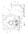
- FIG. 2 shows a perspective view of a gas tank container according to a preferred embodiment of the invention.
- the invention concerns a gas tank container for storing and/or transporting gases and/or liquids, which gas tank container comprises a tank vessel, a frame and at least one outlet valve, wherein the end of said outlet valve is attached to a tank flange, which is preferably sunk between 1 to 30 cm in a recess of a tank end of said tank vessel, more preferably 5 to 20 cm, most preferably 10 to 15 cm.
- fitting outlet valves in the non-recessed variant is an obstacle which prevents the maximum vessel length from being achieved within the frame length.
- a portion of the outlet valve is sunk in a recess. Said recess results in a small loss of volume of the tank vessel, but makes it possible to optimize the length of the tank vessel inside the frame. The volume of the tank vessel consequently increases. This offers the advantage of an increased transport volume within the same frame dimensions.
- At least one outlet valve of the gas tank container comprises a first valve and the first valve is situated within a recess of the tank vessel.
- At least one outlet valve of the gas tank container comprises a first valve, a second valve and a seal and the first and second valves are situated inside a recess of the tank vessel.
- the gas tank container is approximately 20 feet (6,058 mm) long, 8 feet (2,438 mm) wide and 8 (2,438 mm) or 8.6 feet (2,591 mm) high.
- the volume of the gas tank container is preferably at least 24,000 l, more preferably at least 24,500 l and most preferably at least 25,000 l.
- the gas tank container is approximately 30 feet (9,125 mm) long, 8 feet (2,438 mm) wide and 8 (2,438 mm) or 8.6 feet (2,591 mm) high.
- the volume of the gas tank container is preferably at least 38,000 l, more preferably at least 38,500 l and most preferably at least 39,000 l.
- the gas tank container is approximately 40 feet (12,192 mm) long, 8 feet (2,438 mm) wide and 8 (2,438 mm) or 8.6 feet (2,591 mm) high.
- the volume of the gas tank container is preferably at least 51,500 l, more preferably at least 52,000 l and most preferably at least 52,500 l.
- the gas tank container comprises a loading and unloading connection and a vapor-return connection.
- At least one manhole is provided which is situated in the casing or in a bottom of the tank vessel.
- the loading and unloading connection is connected to a supply duct which is situated inside the tank vessel and the end of which supply duct is directed toward the bottom of the tank vessel.
- FIG. 1 a shows a partial cross-sectional view of a gas tank container ( 1 ) according to the prior art along the longitudinal axis of a gas tank container.
- the gas tank container ( 1 ) is provided with a cylindrical tank vessel ( 2 ) and a frame ( 3 ) which comprises two lateral frames ( 4 ). These lateral frames ( 4 ) support the tank vessel ( 2 ).
- the tank vessel ( 2 ) is composed of different components which have been welded together, the weld seams ( 8 ) being illustrated in the figure.
- the gas tank container ( 1 ) is provided with a vapor-return connection ( 20 ) and a loading and unloading connection ( 21 ), the latter being visible in the cross-sectional view.
- the loading and unloading connection ( 21 ) is attached to a flange ( 22 ) external to the tank vessel ( 2 ).
- the loading and unloading connection ( 21 ) is connected to a supply duct ( 31 ) which is situated inside the tank vessel ( 2 ).
- FIG. 1 b shows a partial cross-sectional view of a gas tank container along the longitudinal axis of a gas tank container, according to a preferred embodiment of the invention. This figure is a similar cross-sectional view as that of the prior art gas tank container in FIG. 1 a.
- the loading and unloading connection ( 21 ) is attached to a flange ( 22 ) which is not external to the tank vessel ( 2 ), but internal to the tank vessel ( 2 ).
- the tank flange is therefore recessed in the vessel ( 2 ).
- the length of the tank vessel within the frame ( 3 ) can be selected to be greater than is the case with a prior art gas tank container (see FIG. 1 a ).
- the total volume of the tank vessel is increased.
- the gas tank container ( 1 ) is also provided with a manometer ( 41 ) which is connected to the pipe ( 32 ) inside the tank vessel ( 2 ).
- FIG. 2 shows a perspective view of a gas tank container according to a preferred embodiment of the invention.
- the front and rear frame ( 4 ) support the tank vessel ( 2 ) by means of two support saddles ( 19 ), each of which is connected to a head-end frame ( 6 ) on the two head ends ( 13 ) of the tank container ( 1 ) via support struts ( 18 ).
- the front frame or rear frame ( 4 ) comprises a support saddle ( 19 ), two support struts ( 18 ) and a head-end frame ( 6 ).
- Each head-end frame is provided with two upper and two lower corner pieces ( 7 ).
- the head-end frames ( 6 ) comprise upper and lower transverse beams ( 15 , 14 ) and corner supports ( 16 ) which are fitted between the corner pieces ( 7 ).
- the head-end frames ( 6 ) are reinforced by means of diagonal struts ( 17 ) which are fitted therein.
- This gas tank container ( 1 ) is provided with a manhole ( 10 ) in a tank end of the tank vessel ( 2 ).
- the manhole ( 10 ) is closed off by means of a manhole lid ( 12 ) using manhole bolts ( 11 ).
- the gas tank container ( 1 ) is provided with a vapor-return connection ( 20 ) and a loading and unloading connection ( 21 ).
- the vapor-return connection ( 20 ) and the loading and unloading connection ( 21 ) are each attached to a flange ( 22 ) which is sunk into a recess ( 23 ) in the tank vessel ( 2 ).
- the loading and unloading connection ( 21 ) is connected to a supply duct ( 31 ) which is situated inside the tank vessel ( 2 ).
- a combination handle ( 33 ) connects the vapor-return connection ( 20 ) and a loading and unloading connection ( 21 ).
- both outlet valves can be closed off and opened simultaneously.
- thermometer ( 40 ) and a manometer ( 41 ) are provided in the rear cabinet ( 52 ) in order to display the temperature and the pressure inside the tank vessel ( 2 ), respectively.
- This rear cabinet ( 52 ) may be closed by means of a cover blind ( 9 ).
Landscapes
- Engineering & Computer Science (AREA)
- Mechanical Engineering (AREA)
- General Engineering & Computer Science (AREA)
- Filling Or Discharging Of Gas Storage Vessels (AREA)
Abstract
A gas tank container having increased volume is disclosed. The gas tank container for storing and/or transporting gas and/or liquid, includes a tank vessel, a frame and at least one outlet valve. The end of the outlet valve is attached to a tank flange, which is sunk in a recess at the end of the tank vessel. By recessing at least one outlet valve of the gas tank container, the length of the tank vessel can be optimized within the frame.
Description
This application claims priority to BE2012/0769 filed Nov. 13, 2012, which is incorporated by reference in its entirety.
The present invention relates to increasing the volume of a gas tank container.
A gas tank container is an intermodal container for transporting liquids and/or gases. A standard gas tank container has a manhole and at least one connector. Loading and unloading takes place by connecting hoses from the loading and unloading installation to connectors of the gas tank container, following which loading or unloading can be effected. A connector is part of a valve, also referred to as an outlet valve, which can, if necessary, interrupt the supply or discharge of liquids and/or gases. In accordance with legal requirements, the connections are made by means of a composite valve.
Documents U.S. Pat. No. 7,322,227B2 and CA2765684A1 relate to examples of a prior art tank container.
The known intermodal gas tank containers suffer from the problem that the volume is limited by the dimensions of the frame around the container and by the space which the outlet valve takes up on the container and which has to stay inside (the casing of) the ISO frame.
A gas tank container is usually provided with a loading and unloading connection and a vapor-return connection. Tank connections have to satisfy the international requirements regarding the various transportation modes. This means that they have to contain a threefold serial safeguard: an inner valve which is protected against external damage, a second valve (e.g. ball valve) in line therewith and finally a seal, for example, in the form of a blind flange. This threefold protection is intended to prevent leaks and unintentional opening of connections. Depending on the infrastructure, gas tanks are operated either at the rear or at the side. In both cases, the available space is limited. The various suppliers offer compact threefold tank connections which satisfy the abovementioned requirements. Despite their compact construction, the length of these tank connections forms a limitation with regard to the tank volume which is possible within the ISO dimensions of the containers in the case of rear connections.
It is an object of the present invention to improve the design of a gas tank container to offer a solution to at least one of the aforementioned drawbacks when transporting gases, as described in claim 1.
The invention relates in particular to a gas tank container for storing and/or transporting gases and/or liquids, which gas tank container comprises a tank vessel, a frame and at least one outlet valve, wherein the end of said outlet valve is attached to a tank flange, which is preferably sunk between 1 to 30 cm in a recess of a tank end of said tank vessel, more preferably 5 to 20 cm, most preferably 10 to 15 cm, as described in claim 1.
In preferred embodiments, at least one outlet valve of the gas tank container includes a first valve and the first valve is situated inside a recess of the tank vessel. More preferably, at least one outlet valve of the gas tank container includes a first valve, a second valve and a seal and the first and second valve are situated within a recess of the tank vessel.
In preferred embodiments, at least one manhole is provided which is situated in the casing or in a tank end of the tank vessel.
In some preferred embodiments, the frame includes a front and rear frame which are attached to the ends of the gas tank container.
In some preferred embodiments, the gas tank container is approximately 20 feet (6,058 mm) long, 8 feet (2,438 mm) wide and 8 (2,438 mm) or 8.6 feet (2,591 mm) high. Preferably, the volume of the gas tank container is at least 24,000 l, more preferably at least 24,500 l and most preferably at least 25,000 l.
In some preferred embodiments, the gas tank container is approximately 30 feet (9,125 mm) long, 8 feet (2,438 mm) wide and 8 (2,438 mm) or 8.6 feet (2,591 mm) high. Preferably, the volume of the gas tank container is at least 38,000 l, more preferably at least 38,500 l and most preferably at least 39,000 l.
In some preferred embodiments, the gas tank container is approximately 40 feet (12,192 mm) long, 8 feet (2,438 mm) wide and 8 (2,438 mm) or 8.6 feet (2,591 mm) high. Preferably, the volume of the gas tank container is at least 51,500 l, more preferably at least 52,000 l and most preferably at least 52,500 l.
By recessing at least one outlet valve of a gas tank container, the length of the tank vessel can be optimized within the frame.
The figures below illustrate preferred embodiments of the invention.
Below, the invention will be described with reference to non-limiting examples which illustrate the invention and which are not intended to and may not be interpreted as limiting the scope of the invention.
In a first aspect, the invention concerns a gas tank container for storing and/or transporting gases and/or liquids, which gas tank container comprises a tank vessel, a frame and at least one outlet valve, wherein the end of said outlet valve is attached to a tank flange, which is preferably sunk between 1 to 30 cm in a recess of a tank end of said tank vessel, more preferably 5 to 20 cm, most preferably 10 to 15 cm.
Usually, fitting outlet valves in the non-recessed variant is an obstacle which prevents the maximum vessel length from being achieved within the frame length. By recessing a flange in the tank vessel and attaching such an outlet valve, a portion of the outlet valve is sunk in a recess. Said recess results in a small loss of volume of the tank vessel, but makes it possible to optimize the length of the tank vessel inside the frame. The volume of the tank vessel consequently increases. This offers the advantage of an increased transport volume within the same frame dimensions.
In a preferred embodiment of the invention, at least one outlet valve of the gas tank container comprises a first valve and the first valve is situated within a recess of the tank vessel.
In a preferred embodiment of the invention, at least one outlet valve of the gas tank container comprises a first valve, a second valve and a seal and the first and second valves are situated inside a recess of the tank vessel.
In a preferred embodiment of the invention, the gas tank container is approximately 20 feet (6,058 mm) long, 8 feet (2,438 mm) wide and 8 (2,438 mm) or 8.6 feet (2,591 mm) high. In a more preferred embodiment, the volume of the gas tank container is preferably at least 24,000 l, more preferably at least 24,500 l and most preferably at least 25,000 l.
In a preferred embodiment of the invention, the gas tank container is approximately 30 feet (9,125 mm) long, 8 feet (2,438 mm) wide and 8 (2,438 mm) or 8.6 feet (2,591 mm) high. In a more preferred embodiment, the volume of the gas tank container is preferably at least 38,000 l, more preferably at least 38,500 l and most preferably at least 39,000 l.
In a preferred embodiment of the invention, the gas tank container is approximately 40 feet (12,192 mm) long, 8 feet (2,438 mm) wide and 8 (2,438 mm) or 8.6 feet (2,591 mm) high. In a more preferred embodiment, the volume of the gas tank container is preferably at least 51,500 l, more preferably at least 52,000 l and most preferably at least 52,500 l.
In a preferred embodiment of the invention, the gas tank container comprises a loading and unloading connection and a vapor-return connection.
In a preferred embodiment of the invention, at least one manhole is provided which is situated in the casing or in a bottom of the tank vessel.
In a preferred embodiment of the invention, the loading and unloading connection is connected to a supply duct which is situated inside the tank vessel and the end of which supply duct is directed toward the bottom of the tank vessel.
Prior Art:
The gas tank container (1) is provided with a cylindrical tank vessel (2) and a frame (3) which comprises two lateral frames (4). These lateral frames (4) support the tank vessel (2). The tank vessel (2) is composed of different components which have been welded together, the weld seams (8) being illustrated in the figure.
The gas tank container (1) is provided with a vapor-return connection (20) and a loading and unloading connection (21), the latter being visible in the cross-sectional view. The loading and unloading connection (21) is attached to a flange (22) external to the tank vessel (2). The loading and unloading connection (21) is connected to a supply duct (31) which is situated inside the tank vessel (2).
Invention:
In this figure, the loading and unloading connection (21) is attached to a flange (22) which is not external to the tank vessel (2), but internal to the tank vessel (2). The tank flange is therefore recessed in the vessel (2). As a result thereof, the length of the tank vessel within the frame (3) can be selected to be greater than is the case with a prior art gas tank container (see FIG. 1a ). Despite the loss of volume due to the recess for, for example, the loading and unloading connection (21), the total volume of the tank vessel is increased.
The gas tank container (1) is also provided with a manometer (41) which is connected to the pipe (32) inside the tank vessel (2).
The front and rear frame (4) support the tank vessel (2) by means of two support saddles (19), each of which is connected to a head-end frame (6) on the two head ends (13) of the tank container (1) via support struts (18). The front frame or rear frame (4) comprises a support saddle (19), two support struts (18) and a head-end frame (6). Each head-end frame is provided with two upper and two lower corner pieces (7). The head-end frames (6) comprise upper and lower transverse beams (15, 14) and corner supports (16) which are fitted between the corner pieces (7). In addition, the head-end frames (6) are reinforced by means of diagonal struts (17) which are fitted therein.
This gas tank container (1) is provided with a manhole (10) in a tank end of the tank vessel (2). The manhole (10) is closed off by means of a manhole lid (12) using manhole bolts (11).
The gas tank container (1) is provided with a vapor-return connection (20) and a loading and unloading connection (21). The vapor-return connection (20) and the loading and unloading connection (21) are each attached to a flange (22) which is sunk into a recess (23) in the tank vessel (2). The loading and unloading connection (21) is connected to a supply duct (31) which is situated inside the tank vessel (2).
A combination handle (33) connects the vapor-return connection (20) and a loading and unloading connection (21). Thus, both outlet valves can be closed off and opened simultaneously.
Furthermore, in addition to the outlet valves, a thermometer (40) and a manometer (41) are provided in the rear cabinet (52) in order to display the temperature and the pressure inside the tank vessel (2), respectively. This rear cabinet (52) may be closed by means of a cover blind (9).
It is supposed that the present invention is not limited to the above-described embodiments and that some changes and modifications may be made to the examples described without re-evaluating the attached claims.
Claims (12)
1. A gas tank container for storing and/or transporting gas, which gas tank container comprises:
a gas tank vessel comprising a pressurized gas,
a frame,
at least one outlet valve, and
at least one vapor-return connection,
wherein the end of said outlet valve and said vapor-return connection are attached to a gas tank flange, which is sunk between 1 to 30 cm in a recess of a curved tank end of said gas tank vessel, wherein said frame comprises a volume constraint with respect to said gas tank vessel, wherein a portion of said curved tank end surrounding said recess entirely circumferentially is extended toward said frame with respect to said tank flange for adding a volume surrounding said recess entirely circumferentially to a volume of said gas tank vessel,
wherein said gas tank vessel comprises a supply duct for the supply or discharge of a gas, wherein said supply duct comprises a first end connected to said tank flange, and a second end being a free end located in the interior of the gas tank vessel,
wherein the recess is located entirely and at least 10 cm above said second end of said supply duct and within the lower half of the gas tank vessel.
2. The gas tank container according to claim 1 , wherein at least one outlet valve of the gas tank container comprises a first valve and wherein the first valve is situated inside a recess of the tank vessel.
3. The gas tank container according to claim 2 , wherein at least one outlet valve of the gas tank container comprises a first valve, a second valve and a seal and wherein the first and second valve are situated within a recess of the tank vessel.
4. The gas tank container according to claim 1 , wherein at least one manhole is provided which is situated in a casing or in a tank end of the tank vessel.
5. The gas tank container according to claim 1 , wherein the frame comprises a front and rear frame which are attached to the ends of the gas tank container.
6. The gas tank container according to claim 1 , wherein the gas tank container is approximately 20 feet (6,058 mm) long, 8 feet (2,438 mm) wide and 8 (2,438 mm) or 8.6 feet (2,591 mm) high.
7. The gas tank container according to claim 6 , wherein the volume of the gas tank container is at least 24,000 l.
8. The gas tank container according to claim 1 , wherein the gas tank container is approximately 30 feet (9,125 mm) long, 8 feet (2,438 mm) wide and 8 (2,438 mm) or 8.6 feet (2,591 mm) high.
9. The gas tank container according to claim 8 , wherein the volume of the gas tank container is at least 38,000 l.
10. The gas tank container according to claim 1 , wherein the gas tank container is approximately 40 feet (12,192 mm) long, 8 feet (2,438 mm) wide and 8 (2,438 mm) or 8.6 feet (2,591 mm) high.
11. The gas tank container according to claim 10 , wherein the volume of the gas tank container is at least 51,500 l.
12. The gas tank container according to claim 1 , wherein said second end is directed toward a sump provided in a bottom of said gas tank vessel, wherein said second end belongs to an essentially straight dip tube belonging to said supply duct, and wherein said second end comprises a dip tube bottom opening which is provided according to a non-orthogonal cross-section of said dip tube.
Applications Claiming Priority (3)
| Application Number | Priority Date | Filing Date | Title |
|---|---|---|---|
| BE2012/0769 | 2012-11-13 | ||
| BE201200769A BE1020604A3 (en) | 2012-11-13 | 2012-11-13 | DEVICE OF A HOST TANK CONTAINER. |
| BEBE2012/0769 | 2012-11-13 |
Publications (2)
| Publication Number | Publication Date |
|---|---|
| US20140130914A1 US20140130914A1 (en) | 2014-05-15 |
| US9863582B2 true US9863582B2 (en) | 2018-01-09 |
Family
ID=47435669
Family Applications (1)
| Application Number | Title | Priority Date | Filing Date |
|---|---|---|---|
| US14/078,872 Active 2033-11-21 US9863582B2 (en) | 2012-11-13 | 2013-11-13 | Gas tank container |
Country Status (3)
| Country | Link |
|---|---|
| US (1) | US9863582B2 (en) |
| EP (1) | EP2730832B1 (en) |
| BE (1) | BE1020604A3 (en) |
Families Citing this family (6)
| Publication number | Priority date | Publication date | Assignee | Title |
|---|---|---|---|---|
| US11091317B2 (en) * | 2014-05-06 | 2021-08-17 | Jwf Industries, Inc. | Vertical fluid storage tank with connecting ports |
| DE202015100455U1 (en) | 2015-01-30 | 2015-02-10 | Welfit Oddy (Pty) Limited | terminal assembly |
| BE1023050B1 (en) * | 2015-06-19 | 2016-11-14 | Van Hool Nv. | DEVICE FOR A TANK CONTAINER WITH INCREASED VOLUME AND LOADING POWER |
| CN106315051A (en) * | 2016-11-11 | 2017-01-11 | 天津新华昌运输设备有限公司 | 28-cube tank container for railway transportation |
| FR3064045B1 (en) | 2017-03-17 | 2021-10-22 | Cryolor | TRANSPORTABLE FLUID TANK |
| DE102019215429A1 (en) | 2019-06-19 | 2020-12-24 | Continental Teves Ag & Co. Ohg | Pedal actuation unit |
Citations (19)
| Publication number | Priority date | Publication date | Assignee | Title |
|---|---|---|---|---|
| US1469646A (en) * | 1920-08-06 | 1923-10-02 | Charles L Rowland | Protector for valves of containers |
| US1602506A (en) * | 1922-02-01 | 1926-10-12 | Shippers Car Line Corp | Container |
| US2189945A (en) * | 1936-07-28 | 1940-02-13 | Motor Terminals Inc | Demountable tank body |
| US2271660A (en) * | 1938-01-04 | 1942-02-03 | Nat Fitch Corp | Demountable freight container for liquids |
| US2609964A (en) * | 1947-04-04 | 1952-09-09 | American Pipe & Steel Corp | Recess mounting for valves and fittings for liquefied petroleum gas containers |
| US2673010A (en) * | 1950-07-14 | 1954-03-23 | James R Barrow | Pressure tank |
| US3577739A (en) * | 1968-10-29 | 1971-05-04 | Freuhauf Corp | Method and apparatus for transporting liquefied gas |
| US3776283A (en) * | 1972-06-15 | 1973-12-04 | Gulf Research Development Co | Vapor recovery system |
| US4320788A (en) * | 1975-06-23 | 1982-03-23 | Union Oil Company Of California | Apparatus for the bulk delivery of volatile liquids |
| US4932551A (en) * | 1989-03-31 | 1990-06-12 | Hoover Group, Inc. | Composite tank assembly |
| US5156268A (en) * | 1990-12-10 | 1992-10-20 | Hoover Group, Inc. | Composite shipping container for combustible liquids |
| US6012598A (en) * | 1997-06-09 | 2000-01-11 | The Columbiana Boiler Company | Freight container |
| US20050189357A1 (en) * | 2004-02-27 | 2005-09-01 | Fuji Photo Film Co., Ltd. | Transport tank and transporting method thereof |
| US20070261756A1 (en) | 2006-04-13 | 2007-11-15 | Kiyoshi Handa | High Pressure Gas Tank Cooling by Ejector Pump Circulation |
| US7322227B2 (en) | 2004-08-02 | 2008-01-29 | China International Marine Containers (Group) Co., Ltd. | Tank container with electronic monitoring device |
| US20080067178A1 (en) | 2006-09-15 | 2008-03-20 | Polyearn Development Corporation | Portable tank and tank container for liquefied gas transportation |
| US20080087665A1 (en) | 2006-10-13 | 2008-04-17 | Columbiana Boiler Company, Llc | Freight container |
| CA2765684A1 (en) | 2009-06-18 | 2010-12-23 | International Transport Equipment Corporation | Intermodal tank transport system, components, and methods |
| US20130193150A1 (en) * | 2012-01-30 | 2013-08-01 | Neal Keefer | Molded fuel tank and method of manufacturing the same |
Family Cites Families (1)
| Publication number | Priority date | Publication date | Assignee | Title |
|---|---|---|---|---|
| US9222622B2 (en) * | 2007-11-26 | 2015-12-29 | Air Products And Chemicals, Inc. | Vessels with personnel access provisions |
-
2012
- 2012-11-13 BE BE201200769A patent/BE1020604A3/en active
-
2013
- 2013-11-13 US US14/078,872 patent/US9863582B2/en active Active
- 2013-11-13 EP EP13192751.9A patent/EP2730832B1/en active Active
Patent Citations (20)
| Publication number | Priority date | Publication date | Assignee | Title |
|---|---|---|---|---|
| US1469646A (en) * | 1920-08-06 | 1923-10-02 | Charles L Rowland | Protector for valves of containers |
| US1602506A (en) * | 1922-02-01 | 1926-10-12 | Shippers Car Line Corp | Container |
| US2189945A (en) * | 1936-07-28 | 1940-02-13 | Motor Terminals Inc | Demountable tank body |
| US2271660A (en) * | 1938-01-04 | 1942-02-03 | Nat Fitch Corp | Demountable freight container for liquids |
| US2609964A (en) * | 1947-04-04 | 1952-09-09 | American Pipe & Steel Corp | Recess mounting for valves and fittings for liquefied petroleum gas containers |
| US2673010A (en) * | 1950-07-14 | 1954-03-23 | James R Barrow | Pressure tank |
| US3577739A (en) * | 1968-10-29 | 1971-05-04 | Freuhauf Corp | Method and apparatus for transporting liquefied gas |
| US3776283A (en) * | 1972-06-15 | 1973-12-04 | Gulf Research Development Co | Vapor recovery system |
| US4320788A (en) * | 1975-06-23 | 1982-03-23 | Union Oil Company Of California | Apparatus for the bulk delivery of volatile liquids |
| US4932551A (en) * | 1989-03-31 | 1990-06-12 | Hoover Group, Inc. | Composite tank assembly |
| US5156268A (en) * | 1990-12-10 | 1992-10-20 | Hoover Group, Inc. | Composite shipping container for combustible liquids |
| US6012598A (en) * | 1997-06-09 | 2000-01-11 | The Columbiana Boiler Company | Freight container |
| US20050189357A1 (en) * | 2004-02-27 | 2005-09-01 | Fuji Photo Film Co., Ltd. | Transport tank and transporting method thereof |
| US7322227B2 (en) | 2004-08-02 | 2008-01-29 | China International Marine Containers (Group) Co., Ltd. | Tank container with electronic monitoring device |
| US20070261756A1 (en) | 2006-04-13 | 2007-11-15 | Kiyoshi Handa | High Pressure Gas Tank Cooling by Ejector Pump Circulation |
| US20080067178A1 (en) | 2006-09-15 | 2008-03-20 | Polyearn Development Corporation | Portable tank and tank container for liquefied gas transportation |
| US20080087665A1 (en) | 2006-10-13 | 2008-04-17 | Columbiana Boiler Company, Llc | Freight container |
| CA2765684A1 (en) | 2009-06-18 | 2010-12-23 | International Transport Equipment Corporation | Intermodal tank transport system, components, and methods |
| US8827313B2 (en) * | 2009-06-18 | 2014-09-09 | International Transport Equipment Corporation | Intermodal tank transport system, components, and methods |
| US20130193150A1 (en) * | 2012-01-30 | 2013-08-01 | Neal Keefer | Molded fuel tank and method of manufacturing the same |
Also Published As
| Publication number | Publication date |
|---|---|
| BE1020604A3 (en) | 2014-01-07 |
| EP2730832A2 (en) | 2014-05-14 |
| EP2730832B1 (en) | 2024-03-13 |
| US20140130914A1 (en) | 2014-05-15 |
| EP2730832A3 (en) | 2018-02-28 |
Similar Documents
| Publication | Publication Date | Title |
|---|---|---|
| US9863582B2 (en) | Gas tank container | |
| KR101978332B1 (en) | ISO LNG Tank Container | |
| US9701467B2 (en) | Combination tank | |
| US10427580B2 (en) | Cargo tank assemblies with ground level access | |
| KR20130033003A (en) | Pump tower | |
| US20080087665A1 (en) | Freight container | |
| KR102108348B1 (en) | Pump tower having bottom bracket | |
| US20110186581A1 (en) | Multiple-walled storage tank | |
| US11608939B2 (en) | Support structure for shortened cryogenic transport trailer | |
| CN106678535A (en) | Tank | |
| CN104456060A (en) | Low-temperature storage and transportation container for railway transportation | |
| US4315531A (en) | Transport container | |
| WO2017031520A1 (en) | Water storage and transport system | |
| KR102351018B1 (en) | Liquefied natural gas storage iso tank container | |
| JP5953286B2 (en) | Container for powder transfer | |
| JP2005059913A (en) | Tank container | |
| JP2010101356A (en) | Low-temperature liquefied gas storage tank | |
| RU178764U1 (en) | Tank container for transportation and storage of hydrogen peroxide | |
| AU2014311044B2 (en) | Bulk container and ventilation device thereof | |
| KR20150015731A (en) | Pump tower pipe structure | |
| KR101764229B1 (en) | Structure of liquid cargo storage tank | |
| KR200440011Y1 (en) | Structures of a lng storage tank | |
| CN104986416A (en) | All-closed nuclear biochemical storage transportation tank | |
| KR101701727B1 (en) | Pump tower | |
| KR101804582B1 (en) | Installation structure of cargo heater and booster pump for liquefied natural gas carrier |
Legal Events
| Date | Code | Title | Description |
|---|---|---|---|
| AS | Assignment |
Owner name: VAN HOOL NV, BELGIUM Free format text: ASSIGNMENT OF ASSIGNORS INTEREST;ASSIGNORS:MERTENS, EDDY;VAN HAAREN, JAN;SIGNING DATES FROM 20131202 TO 20131203;REEL/FRAME:031753/0859 |
|
| STCF | Information on status: patent grant |
Free format text: PATENTED CASE |
|
| MAFP | Maintenance fee payment |
Free format text: PAYMENT OF MAINTENANCE FEE, 4TH YEAR, LARGE ENTITY (ORIGINAL EVENT CODE: M1551); ENTITY STATUS OF PATENT OWNER: LARGE ENTITY Year of fee payment: 4 |