US9854905B2 - Sliding-pivoting mechanism of a shelf of a piece of furniture or of a domestic appliance, piece of furniture, and domestic appliance - Google Patents
Sliding-pivoting mechanism of a shelf of a piece of furniture or of a domestic appliance, piece of furniture, and domestic appliance Download PDFInfo
- Publication number
- US9854905B2 US9854905B2 US15/315,466 US201515315466A US9854905B2 US 9854905 B2 US9854905 B2 US 9854905B2 US 201515315466 A US201515315466 A US 201515315466A US 9854905 B2 US9854905 B2 US 9854905B2
- Authority
- US
- United States
- Prior art keywords
- sliding
- pivoting mechanism
- pivoting
- locking
- shelf
- Prior art date
- Legal status (The legal status is an assumption and is not a legal conclusion. Google has not performed a legal analysis and makes no representation as to the accuracy of the status listed.)
- Active
Links
Images




Classifications
-
- A—HUMAN NECESSITIES
- A47—FURNITURE; DOMESTIC ARTICLES OR APPLIANCES; COFFEE MILLS; SPICE MILLS; SUCTION CLEANERS IN GENERAL
- A47B—TABLES; DESKS; OFFICE FURNITURE; CABINETS; DRAWERS; GENERAL DETAILS OF FURNITURE
- A47B46/00—Cabinets, racks or shelf units, having one or more surfaces adapted to be brought into position for use by extending or pivoting
- A47B46/005—Cabinets, racks or shelf units, having one or more surfaces adapted to be brought into position for use by extending or pivoting by displacement in a vertical plane; by rotating about a horizontal axis
-
- A—HUMAN NECESSITIES
- A47—FURNITURE; DOMESTIC ARTICLES OR APPLIANCES; COFFEE MILLS; SPICE MILLS; SUCTION CLEANERS IN GENERAL
- A47L—DOMESTIC WASHING OR CLEANING; SUCTION CLEANERS IN GENERAL
- A47L15/00—Washing or rinsing machines for crockery or tableware
- A47L15/42—Details
- A47L15/50—Racks ; Baskets
- A47L15/506—Arrangements for lifting racks for loading or unloading purposes
-
- A—HUMAN NECESSITIES
- A47—FURNITURE; DOMESTIC ARTICLES OR APPLIANCES; COFFEE MILLS; SPICE MILLS; SUCTION CLEANERS IN GENERAL
- A47L—DOMESTIC WASHING OR CLEANING; SUCTION CLEANERS IN GENERAL
- A47L15/00—Washing or rinsing machines for crockery or tableware
- A47L15/42—Details
- A47L15/50—Racks ; Baskets
- A47L15/507—Arrangements for extracting racks, e.g. roller supports
-
- F—MECHANICAL ENGINEERING; LIGHTING; HEATING; WEAPONS; BLASTING
- F24—HEATING; RANGES; VENTILATING
- F24C—DOMESTIC STOVES OR RANGES ; DETAILS OF DOMESTIC STOVES OR RANGES, OF GENERAL APPLICATION
- F24C15/00—Details
- F24C15/16—Shelves, racks or trays inside ovens; Supports therefor
-
- F—MECHANICAL ENGINEERING; LIGHTING; HEATING; WEAPONS; BLASTING
- F16—ENGINEERING ELEMENTS AND UNITS; GENERAL MEASURES FOR PRODUCING AND MAINTAINING EFFECTIVE FUNCTIONING OF MACHINES OR INSTALLATIONS; THERMAL INSULATION IN GENERAL
- F16M—FRAMES, CASINGS OR BEDS OF ENGINES, MACHINES OR APPARATUS, NOT SPECIFIC TO ENGINES, MACHINES OR APPARATUS PROVIDED FOR ELSEWHERE; STANDS; SUPPORTS
- F16M2200/00—Details of stands or supports
- F16M2200/02—Locking means
- F16M2200/025—Locking means for translational movement
-
- F—MECHANICAL ENGINEERING; LIGHTING; HEATING; WEAPONS; BLASTING
- F16—ENGINEERING ELEMENTS AND UNITS; GENERAL MEASURES FOR PRODUCING AND MAINTAINING EFFECTIVE FUNCTIONING OF MACHINES OR INSTALLATIONS; THERMAL INSULATION IN GENERAL
- F16M—FRAMES, CASINGS OR BEDS OF ENGINES, MACHINES OR APPARATUS, NOT SPECIFIC TO ENGINES, MACHINES OR APPARATUS PROVIDED FOR ELSEWHERE; STANDS; SUPPORTS
- F16M2200/00—Details of stands or supports
- F16M2200/06—Arms
- F16M2200/063—Parallelogram arms
Definitions
- the disclosure relates to a sliding-pivoting mechanism of a shelf of a piece of furniture or a domestic appliance for pulling out or raising the shelf from a body of the furniture or from a useful space of a domestic appliance.
- the disclosure further relates to a piece of furniture as well as a domestic appliance with a sliding-pivoting mechanism.
- Such sliding-pivoting mechanisms may be installed for facilitating the use of pieces of furniture or domestic appliances, especially dishwashers or cooking appliances.
- a shelf installed in such a piece of furniture or domestic appliance can be moved by means of a sliding-pivoting mechanism from a bottom position by pulling out and subsequent upward pivoting to an upward position in which a user can conveniently place items on the shelf or remove items placed on said shelf.
- a generic sliding-pivoting mechanism is known for example from WO 2014/03 3092 A1.
- the present disclosure is directed to a sliding-pivoting mechanism in which the locking of the sliding-pivoting mechanism is improved.
- the sliding-pivoting mechanism in accordance with the disclosure comprises a rotatably fixed first and second pivot arm which is fastened to at least one of the side walls of the body of the piece of furniture or of the useful space of the domestic appliance by means of a first end parallel to the plane of the side walls.
- the pivot arms are arranged in parallel at a distance from each other.
- a guide rail is pivotably fastened to the respective second ends of the pivot arms parallel to the plane of the side walls in such a way that the guide rail can be pivoted from a bottom position within the body or the useful space to a lifted, upper position at least partly outside the body or the useful space.
- the shelf is fastened to a running rail which can be moved linearly on or in the guide rail.
- An activator is further fixed to said running rail.
- a locking mechanism of the sliding-pivoting mechanism arranged on the guide rail and on one of the pivot arms can be actuated with said activator, which locking mechanism is used for preventing a pivoting movement of the sliding-pivoting mechanism in a lifted and lowered end position.
- a support element is arranged in a stationary manner on the first pivot arm, which support element interacts with a guide bevel of the activator and with which the locking mechanism can be moved during lifting of the sliding-pivoting mechanism to a locking position which secures the lifted end position, wherein one end of the guide bevel of the activator which is disposed at the front in the pull-out direction is formed as a limit stop.
- This support element allows the user in a simple way to push the shelf slightly against the pull-out direction during lifting of the shelf to the lifted end position shortly before reaching the lifted end position.
- the front end of the guide bevel of the activator which is formed in the pull-out direction as a limit stop, is used for limiting a displacement of the running rail against the pull-out direction up to the lifted end position of the sliding-pivoting mechanism, in which the locking mechanism has reached the locking position. This prevents excessive insertion of the shelf prior to reaching the lifted end position of the shelf.
- the locking mechanism comprises a web with a pin protruding in the direction of the guide rail, which web is pivotably and resiliently mounted on one of the pivot arms and can be guided along a guide element to the guide rail from the locking position securing the lowered end position at least to the locking position securing the lifted end position.
- these locking positions are defined in such a way that locking grooves are provided in the guide element in which the pin rests in the respective locking positions.
- the pin is guided along a guide track which is limited at its ends by locking grooves, which enables a precise coordination of the sequence of movement of the pivot arms.
- the support element is formed as a pin protruding from the first pivot arm.
- the pin can be fastened to the support element as a separate component or can alternatively be integrally attached to the pivot arm as a part thereof.
- the support element is formed as a wheel which protrudes from the first pivot arm and can be rotated about a rotational axis oriented perpendicularly to a plane spanned by the pivoting movement of the pivot arms, so that during lifting of the shelf to its lifted end position may be only necessary to overcome rolling friction of the rotatable wheel, which further improves smooth running of the sliding-pivoting mechanism.
- the activator comprises a first stop according to a preferred embodiment, with which the pin can be moved from a position blocking a pivoting movement of the pivot arms in the first locking groove when pulling the running rail in a pull-out direction A.
- the activator may comprise a web which is inclined in the manner of a ramp in the pull-out direction, with which the pin can be moved out when pulling out the running rail in a pull-out direction.
- FIGS. 1 and 2 show a perspective view of an embodiment of a sliding-pivoting mechanism in accordance with the disclosure in the fully lowered position and a detailed view of the region designated with II in FIG. 1 ;
- FIGS. 3 and 4 show perspective views of the sliding-pivoting mechanism of FIG. 1 after the completed displacement of the running rail from the guide rail prior to lifting the sliding-pivoting mechanism and a detailed view of the region designated with IV in FIG. 3 ;
- FIGS. 5 and 6 show perspective views of the sliding-pivoting mechanism in a position in which the pivoting movement of the pivot arms is released, wherein FIG. 6 shows a detailed view of the section designated with VI in FIG. 5 ;
- FIGS. 7 and 8 show perspective views, which correspond to FIGS. 5 and 6 , of the sliding-pivoting mechanism during a pivoting movement, wherein FIG. 8 shows a detailed view of the section designated with VIII in FIG. 7 ;
- FIGS. 9 and 10 show perspective views, which correspond to FIGS. 7 and 8 , of the sliding-pivoting mechanism in a further progressed state of the pivoting shortly before reaching that the lifted end position, wherein FIG. 10 shows a detailed view of the section designated with X in FIG. 9 ;
- FIGS. 11 and 12 show views corresponding to FIGS. 9 and 10 of the sliding-pivoting mechanism in the lifted end position, wherein FIG. 12 shows a detailed view of the section designated with XII in FIG. 11 ;
- FIG. 13 shows a perspective view of the position of the sliding-pivoting mechanism shown in FIG. 11 from a different perspective;
- FIGS. 14 and 15 show views of the sliding-pivoting mechanism which correspond to FIGS. 11 and 12 during the release of the sliding-pivoting mechanism from the upper locking position, wherein FIG. 15 shows a detailed view of the section designated with XV in FIG. 14 .
- top, bottom, left, right, front, rear, etc. exclusively relate to the respective illustration and position of the sliding-pivoting mechanism, pivot arms, guide rail, running rail, activator and the like, which illustration and position are selected as examples in the illustrations. These terms shall not be understood as restrictive, i.e., these references may change in different operating positions or due to mirror-symmetric design or the like.
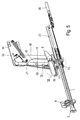
- FIGS. 1 to 15 show an embodiment of a sliding-pivoting mechanism in accordance with the disclosure, wherein exemplary positions of the sliding-pivoting mechanism are shown during a lifting process and a subsequent lowering process.
- the sliding-pivoting mechanism comprises two pivot arms 15 , 16 which are arranged in parallel with respect to each other and spaced from each other.
- the pivot arms 15 , 16 are fastened with a first end via a pivot joint to a side wall retainer 14 .
- the side wall retainer 14 is preferably mounted on a side wall of a piece of furniture or a domestic appliance such as a dishwasher.
- the first ends of the pivot arms 15 , 16 may be pivotally fastened directly to the side wall of the piece of furniture or the domestic appliance.
- the inner wall of domestic appliances is also understood as a side wall.
- the second ends of the pivot arms 15 , 16 which are spaced from the first ends are pivotably fastened on a guide rail 22 of a pull-out guide.
- the pull-out guide comprises at least one running rail 1 which is linearly movable in the guide rail 22 .
- the running rail 1 is preferably coupled via a ball bearing to the guide rail 22 .
- An end stop 53 on the guide rail is used for limiting the path of the running rail 1 in the guide rail 22 .
- the end stop 53 interacts with the ball bearing. It can also be considered to provide other forms of end stops on different fixed or movable parts.
- At least one further movable rail can be arranged between the guide rail 22 and the running rail 1 in order to extend the pull-out.
- a plug 2 may be arranged at the end of the running rail which is at the front in the pull-out direction A, which plug is used for limiting the path of the running rail 1 in the guide rail 22 against the pull-out direction.
- An activator 6 and a fixing apparatus 8 are each fixed to the running rail 1 for fastening the shelf 34 (shown in FIG. 13 ) to the sliding-pivoting mechanism, on which the shelf can be fastened and especially latched.
- a damping unit 30 is arranged on the guide rail 22 , which damping unit can be activated by means of the activator 6 when the shelf 34 travels to its end position in the body of the piece of furniture or the useful space of the domestic appliance.
- the sliding-pivoting mechanism further comprises a locking mechanism which is arranged on the guide rail 22 and on one of the pivot arms 15 , 16 and which can be activated by the activator 6 fixed to the running rail 1 .
- the locking mechanism prevents a pivoting movement of the sliding-pivoting mechanism in a lifted and a lowered end position of the sliding-pivoting mechanism.
- the locking mechanism may consist of a web 18 which is retained in a pivotable and resilient manner on one of the pivot arms 15 , 16 and on which a pin 19 is provided which protrudes in the direction of the guide rail 22 .
- the web 18 may be pivotably held via a rotating pin 21 on the pivot arm 15 .
- a spring element 20 is used for resilient retaining, which spring element rests on the one hand on the web 18 and on the other hand on the pivot arm 15 .
- the pin 19 is in operative connection with a guide element 17 .
- Said guide element 17 which is shown by way of example in FIG. 6 , substantially consists of a plate-shaped element, having an edge formed as a guide track 28 which is limited by two locking grooves 23 , 24 .
- the locking positions of the locking mechanism are the positions in which the pin 19 , which is arranged on the resiliently retained web 18 , rests in one of the two locking grooves 23 , 24 .
- the bottom locking position is shown in FIGS. 1 and 2 .
- the first pivot arm 15 further comprises for the guidance of the pin 19 an end 25 extending perpendicularly to the longitudinal axis of the first pivot arm 15 and having a guide groove 26 through which the pin 19 extends.
- the activator 6 comprises a first stop 7 with which the pin 19 , during extension of the running rail 1 in a pull-out direction A, can be moved from a position in the first locking groove 23 which blocks a pivoting movement of the pivot arms 15 , 16 .
- FIGS. 7 and 8 A partly lifted position of the sliding-pivoting mechanism is shown in FIGS. 7 and 8 . In this position, the running rail 1 is completely pushed out of the guide rail 22 in the forward direction.
- the pin 19 is moved along the guide track 28 along the guide element from the first locking groove 23 in the direction of the second locking groove 24 during the lifting process as a result of the pivoting of the pivot arms 15 , 16 .
- FIGS. 9 and 10 show a position of the sliding-pivoting mechanism shortly before reaching the upper end position, in which the pin 19 has nearly reached the second locking groove 24 .
- the guide bevel 29 is formed in such a way that the user is caused to displace the shelf 34 and thus the running rail 1 and thus the activator 6 slightly against the pull-out direction A in the direction of the furniture body or in the direction of the useful space of the domestic appliance.
- one end of the activator 6 which is at the rear in the pull-out direction A is pushed onto a support element 60 which is arranged in a stationary manner on the first pivot arm 15 , with which the locking mechanism can be moved for lifting the sliding-pivoting mechanism to a locking position representative of the lifted end position 7 .
- the support element 60 is formed as a pin protruding from the first pivot arm 15 .
- Said pin can be fixed as a separate component to the first pivot arm 15 or can also be formed as a pin which is integrally attached to the first pivot arm 15 .
- the support element 60 can also be considered to form the support element 60 as a wheel which protrudes from the first pivot arm 15 and can be rotated about a rotational axis oriented perpendicularly to a plane spanned by the pivoting movement of the pivot arms 15 , 16 .
- the rear end of the activator 6 which is formed as a guide bevel 29 and in which the bottom edge drops in the manner of a ramp in the pull-out direction A, rests on the support element 60 .
- FIG. 13 shows the sliding-pivoting mechanism in this position from the opposite side.
- the illustration clearly shows that the support element 60 is at the bottom end of the guide bevel 29 of the activator 6 .
- the shelf and thus the running rail 1 and thus the activator 6 are moved at first over a short section in the pull-out direction A.
- a web 33 of the activator 6 which is inclined in a ramp-like manner in the pull-out direction A, engages beneath the pin 19 and lifts it out of the locking groove 24 during the movement of the activator 6 and the pull-out direction and thus releases the pivoting movement of the sliding-pivoting mechanism, so that lowering of the shelf 34 can occur by pivoting the pivot arms 15 , 16 to the bottom end position.
- a lifting and/or lowering aid 31 is provided on at least one of the side walls or the side wall retainer 14 for supporting the lifting and lowering movement of the shelf 34 , with which the pivoting movement of the pivot arms 15 , 16 is supported.
- the lifting or lowering aid 31 is preferably formed as a tension spring which is fastened to respective pins 27 on the side wall retainer or the side wall on the one hand and on the second pivot arm 16 on the other hand.
- a limit stop 32 may be provided on the side wall retainer 14 which upon reaching the upper end position of the second pivot arm 16 strikes thereon.
Landscapes
- Engineering & Computer Science (AREA)
- General Engineering & Computer Science (AREA)
- Mechanical Engineering (AREA)
- Chemical & Material Sciences (AREA)
- Combustion & Propulsion (AREA)
- Drawers Of Furniture (AREA)
- Washing And Drying Of Tableware (AREA)
Applications Claiming Priority (4)
| Application Number | Priority Date | Filing Date | Title |
|---|---|---|---|
| DE102014107959.0A DE102014107959A1 (de) | 2014-06-05 | 2014-06-05 | Schiebe-Schwenkmechanik einer Ablage eines Möbels oder Haushaltsgerätes, Möbel und Haushaltsgerät |
| DE102014107959 | 2014-06-05 | ||
| DE102014107959.0 | 2014-06-05 | ||
| PCT/EP2015/062392 WO2015185636A1 (de) | 2014-06-05 | 2015-06-03 | Schiebe-schwenkmechanik einer ablage eines möbels oder haushaltsgerätes, möbel und haushaltsgerät |
Publications (2)
| Publication Number | Publication Date |
|---|---|
| US20170164733A1 US20170164733A1 (en) | 2017-06-15 |
| US9854905B2 true US9854905B2 (en) | 2018-01-02 |
Family
ID=53366021
Family Applications (1)
| Application Number | Title | Priority Date | Filing Date |
|---|---|---|---|
| US15/315,466 Active US9854905B2 (en) | 2014-06-05 | 2015-06-03 | Sliding-pivoting mechanism of a shelf of a piece of furniture or of a domestic appliance, piece of furniture, and domestic appliance |
Country Status (7)
| Country | Link |
|---|---|
| US (1) | US9854905B2 (de) |
| EP (1) | EP3151700B1 (de) |
| JP (1) | JP2017524401A (de) |
| KR (1) | KR20170016366A (de) |
| CN (1) | CN106413478B (de) |
| DE (1) | DE102014107959A1 (de) |
| WO (1) | WO2015185636A1 (de) |
Cited By (2)
| Publication number | Priority date | Publication date | Assignee | Title |
|---|---|---|---|---|
| US20210339845A1 (en) * | 2018-09-26 | 2021-11-04 | Flyability Sa | Uav with protective outer cage |
| US20220160205A1 (en) * | 2019-03-22 | 2022-05-26 | Paul Hettich Gmbh & Co. Kg | Sliding-pivoting mechanism for a rack of a piece of furniture or of a domestic appliance, and piece of furniture or domestic appliance |
Families Citing this family (11)
| Publication number | Priority date | Publication date | Assignee | Title |
|---|---|---|---|---|
| DE102017210310B4 (de) * | 2017-06-20 | 2023-06-29 | BSH Hausgeräte GmbH | Haushaltsgeschirrspülmaschine |
| TWI632883B (zh) * | 2017-06-20 | 2018-08-21 | 川湖科技股份有限公司 | 用於機櫃的托架總成 |
| KR101939483B1 (ko) * | 2017-08-03 | 2019-01-16 | 엘지전자 주식회사 | 선반지지장치 및 이를 구비하는 조리기기 |
| DE102018111663A1 (de) * | 2018-05-15 | 2019-11-21 | Paul Hettich Gmbh & Co. Kg | Schiebe-Schwenkmechanik einer Ablage eines Möbels oder Haushaltsgerätes und Möbel oder Haushaltsgerät |
| DE102018116210A1 (de) * | 2018-07-04 | 2020-01-09 | Paul Hettich Gmbh & Co. Kg | Ablageboden für ein Möbel oder Haushaltsgerät und Verfahren zur Montage eines Ablagebodens |
| KR102590134B1 (ko) * | 2018-11-13 | 2023-10-18 | 삼성전자주식회사 | 랙 어셈블리 및 이를 갖는 식기세척기 |
| CN109480503B (zh) * | 2018-11-30 | 2021-04-27 | 广东美的厨房电器制造有限公司 | 升降机构和消毒设备 |
| CN109506414B (zh) * | 2018-12-19 | 2020-10-13 | 合肥华凌股份有限公司 | 可升降抽屉及冰箱 |
| DE102019107389A1 (de) * | 2019-03-22 | 2020-09-24 | Paul Hettich Gmbh & Co. Kg | Schiebe-Schwenkmechanik für eine Ablage eines Möbels oder Haushaltsgerätes und Möbel bzw. Haushaltsgerät |
| DE102019113251A1 (de) * | 2019-05-20 | 2020-11-26 | Paul Hettich Gmbh & Co. Kg | Möbelelement |
| EP4048130B1 (de) * | 2019-10-25 | 2023-08-23 | Electrolux Appliances Aktiebolag | Geschirrspüler |
Citations (25)
| Publication number | Priority date | Publication date | Assignee | Title |
|---|---|---|---|---|
| US2590341A (en) * | 1946-02-23 | 1952-03-25 | Orvie E Nabholz | Filing cabinet |
| US2822229A (en) * | 1954-08-02 | 1958-02-04 | Washington Steel Products Inc | Swinging shelf support |
| US2919966A (en) * | 1957-04-01 | 1960-01-05 | Acme Appliance Mfg Company | Retractable shelf |
| US3081138A (en) * | 1961-10-16 | 1963-03-12 | Leo A Stebbins | Lowerable compartment for cabinets |
| US3466108A (en) * | 1967-12-21 | 1969-09-09 | Gen Electric | Door-operated rack extending and retracting means for a front-opening appliance cabinet |
| US3799640A (en) * | 1972-12-04 | 1974-03-26 | Gen Motors Corp | Rack apparatus to prevent tipping of a mobile dishwasher |
| US4134629A (en) * | 1976-07-26 | 1979-01-16 | Roger G. Holmes | Pivotable shelving having an associated pivotable door |
| US4915461A (en) * | 1989-06-07 | 1990-04-10 | Kingsborough Michael R | Storage cabinet retrieval system |
| US5115822A (en) * | 1991-03-20 | 1992-05-26 | Nichols Will E | Dishwasher basket assembly including lift mechanism |
| US5249858A (en) * | 1992-05-04 | 1993-10-05 | Nusser Marjorie A | Motor driven movable cabinet |
| US5308158A (en) * | 1992-08-20 | 1994-05-03 | Doug Vogelgesang | Pull down storage shelf assembly |
| US5971513A (en) * | 1998-03-19 | 1999-10-26 | Cassalia; Alan B. | Easy load extendable/retractable bottom dishwasher rack |
| US6247771B1 (en) * | 2000-08-18 | 2001-06-19 | Evelyn J. Miller | Lower rack lifting device for a dishwasher |
| US20040080245A1 (en) * | 2002-08-08 | 2004-04-29 | Compx International Inc. | Drawer slide latch and release mechanism |
| US20040163687A1 (en) * | 2003-02-26 | 2004-08-26 | Samsung Electronics Co., Ltd. | Dishwasher |
| US20050206282A1 (en) * | 2004-03-17 | 2005-09-22 | Rev-A-Shelf Company Llc. | Shelf lift system |
| US20060066189A1 (en) * | 2004-09-30 | 2006-03-30 | Steve Bond | Shelf extending and lifting system |
| US20080129168A1 (en) | 2006-11-30 | 2008-06-05 | General Electric Company | Dishwasher rack lift system |
| US7621605B2 (en) * | 2004-09-30 | 2009-11-24 | Easy Lift Llc | Shelf extending and lifting system |
| US7770986B1 (en) * | 2007-09-20 | 2010-08-10 | Vaidotas Joseph Simaitis | Overhead pull-out swing-down drawer |
| US20120074080A1 (en) * | 2009-04-30 | 2012-03-29 | Paul Hettich Gmbh & Co., Kg. | Apparatus for adjusting the height of a counter which is guided in a household device by way of at least one pull-out guide |
| US8424693B1 (en) * | 2011-04-11 | 2013-04-23 | James A. Hoover | Rollout drop down shelves |
| US8424983B1 (en) * | 2012-02-10 | 2013-04-23 | Gary Strauss | Motorized upper and lower storage shelves |
| WO2014033092A1 (de) | 2012-08-29 | 2014-03-06 | Paul Hettich Gmbh & Co. Kg | Schiebe-schwenkmechanik einer ablage eines möbels, möbel und haushaltsgerät |
| US20150002005A1 (en) * | 2013-06-27 | 2015-01-01 | Samsung Electronics Co., Ltd. | Dishwasher |
Family Cites Families (4)
| Publication number | Priority date | Publication date | Assignee | Title |
|---|---|---|---|---|
| KR100690645B1 (ko) * | 2004-07-15 | 2007-03-09 | 엘지전자 주식회사 | 바스켓 승강장치를 구비한 냉장고 |
| DE102005013456A1 (de) * | 2005-03-21 | 2006-10-05 | Hammerlit Gmbh | Hebevorrichtung für einen Hubtisch, insbesondere in Transportwagen für Krankenhäuser und/oder Pflegeheime |
| GB2455783B (en) * | 2007-12-21 | 2012-07-18 | Panasonic Mfg Uk Ltd | Controlled door opening in domestic appliances |
| DE202008000088U1 (de) * | 2008-07-11 | 2008-09-18 | Lienert, Achim | Wandhalter für Bretter, Leisten oder Strangprofile |
-
2014
- 2014-06-05 DE DE102014107959.0A patent/DE102014107959A1/de not_active Withdrawn
-
2015
- 2015-06-03 US US15/315,466 patent/US9854905B2/en active Active
- 2015-06-03 EP EP15727637.9A patent/EP3151700B1/de active Active
- 2015-06-03 CN CN201580029620.0A patent/CN106413478B/zh active Active
- 2015-06-03 KR KR1020167034822A patent/KR20170016366A/ko not_active Withdrawn
- 2015-06-03 JP JP2016571244A patent/JP2017524401A/ja active Pending
- 2015-06-03 WO PCT/EP2015/062392 patent/WO2015185636A1/de not_active Ceased
Patent Citations (27)
| Publication number | Priority date | Publication date | Assignee | Title |
|---|---|---|---|---|
| US2590341A (en) * | 1946-02-23 | 1952-03-25 | Orvie E Nabholz | Filing cabinet |
| US2822229A (en) * | 1954-08-02 | 1958-02-04 | Washington Steel Products Inc | Swinging shelf support |
| US2919966A (en) * | 1957-04-01 | 1960-01-05 | Acme Appliance Mfg Company | Retractable shelf |
| US3081138A (en) * | 1961-10-16 | 1963-03-12 | Leo A Stebbins | Lowerable compartment for cabinets |
| US3466108A (en) * | 1967-12-21 | 1969-09-09 | Gen Electric | Door-operated rack extending and retracting means for a front-opening appliance cabinet |
| US3799640A (en) * | 1972-12-04 | 1974-03-26 | Gen Motors Corp | Rack apparatus to prevent tipping of a mobile dishwasher |
| US4134629A (en) * | 1976-07-26 | 1979-01-16 | Roger G. Holmes | Pivotable shelving having an associated pivotable door |
| US4915461A (en) * | 1989-06-07 | 1990-04-10 | Kingsborough Michael R | Storage cabinet retrieval system |
| US5115822A (en) * | 1991-03-20 | 1992-05-26 | Nichols Will E | Dishwasher basket assembly including lift mechanism |
| US5249858A (en) * | 1992-05-04 | 1993-10-05 | Nusser Marjorie A | Motor driven movable cabinet |
| US5308158A (en) * | 1992-08-20 | 1994-05-03 | Doug Vogelgesang | Pull down storage shelf assembly |
| US5971513A (en) * | 1998-03-19 | 1999-10-26 | Cassalia; Alan B. | Easy load extendable/retractable bottom dishwasher rack |
| US6247771B1 (en) * | 2000-08-18 | 2001-06-19 | Evelyn J. Miller | Lower rack lifting device for a dishwasher |
| US20040080245A1 (en) * | 2002-08-08 | 2004-04-29 | Compx International Inc. | Drawer slide latch and release mechanism |
| US20040163687A1 (en) * | 2003-02-26 | 2004-08-26 | Samsung Electronics Co., Ltd. | Dishwasher |
| US20050206282A1 (en) * | 2004-03-17 | 2005-09-22 | Rev-A-Shelf Company Llc. | Shelf lift system |
| US7621605B2 (en) * | 2004-09-30 | 2009-11-24 | Easy Lift Llc | Shelf extending and lifting system |
| US20060066189A1 (en) * | 2004-09-30 | 2006-03-30 | Steve Bond | Shelf extending and lifting system |
| US7731805B2 (en) * | 2006-11-30 | 2010-06-08 | General Electric Company | Dishwasher rack lift system |
| US20080129168A1 (en) | 2006-11-30 | 2008-06-05 | General Electric Company | Dishwasher rack lift system |
| US7770986B1 (en) * | 2007-09-20 | 2010-08-10 | Vaidotas Joseph Simaitis | Overhead pull-out swing-down drawer |
| US20120074080A1 (en) * | 2009-04-30 | 2012-03-29 | Paul Hettich Gmbh & Co., Kg. | Apparatus for adjusting the height of a counter which is guided in a household device by way of at least one pull-out guide |
| US8424693B1 (en) * | 2011-04-11 | 2013-04-23 | James A. Hoover | Rollout drop down shelves |
| US8424983B1 (en) * | 2012-02-10 | 2013-04-23 | Gary Strauss | Motorized upper and lower storage shelves |
| WO2014033092A1 (de) | 2012-08-29 | 2014-03-06 | Paul Hettich Gmbh & Co. Kg | Schiebe-schwenkmechanik einer ablage eines möbels, möbel und haushaltsgerät |
| US20150305493A1 (en) * | 2012-08-29 | 2015-10-29 | Paul Hettich Gmbh & Co. Kg | Sliding and pivoting mechanism of a rack of an item of furniture, item of furniture and domestic appliance |
| US20150002005A1 (en) * | 2013-06-27 | 2015-01-01 | Samsung Electronics Co., Ltd. | Dishwasher |
Non-Patent Citations (3)
| Title |
|---|
| English translation of International Search Report of PCT/EP2015/062392 dated Aug. 21, 2015. |
| International Search Report of PCT/EP2015/062392 dated Aug. 21, 2015. |
| Search Report issued in German Application No. 102014107959.0 dated May 12, 2015. |
Cited By (4)
| Publication number | Priority date | Publication date | Assignee | Title |
|---|---|---|---|---|
| US20210339845A1 (en) * | 2018-09-26 | 2021-11-04 | Flyability Sa | Uav with protective outer cage |
| US12325542B2 (en) * | 2018-09-26 | 2025-06-10 | Flyability Sa | UAV with protective outer cage |
| US20220160205A1 (en) * | 2019-03-22 | 2022-05-26 | Paul Hettich Gmbh & Co. Kg | Sliding-pivoting mechanism for a rack of a piece of furniture or of a domestic appliance, and piece of furniture or domestic appliance |
| US11963650B2 (en) * | 2019-03-22 | 2024-04-23 | Paul Hettich Gmbh & Co. Kg | Sliding-pivoting mechanism for a rack of a piece of furniture or of a domestic appliance, and piece of furniture or domestic appliance |
Also Published As
| Publication number | Publication date |
|---|---|
| JP2017524401A (ja) | 2017-08-31 |
| CN106413478B (zh) | 2019-04-16 |
| CN106413478A (zh) | 2017-02-15 |
| US20170164733A1 (en) | 2017-06-15 |
| EP3151700B1 (de) | 2017-10-04 |
| WO2015185636A1 (de) | 2015-12-10 |
| EP3151700A1 (de) | 2017-04-12 |
| KR20170016366A (ko) | 2017-02-13 |
| DE102014107959A1 (de) | 2015-12-17 |
Similar Documents
| Publication | Publication Date | Title |
|---|---|---|
| US9854905B2 (en) | Sliding-pivoting mechanism of a shelf of a piece of furniture or of a domestic appliance, piece of furniture, and domestic appliance | |
| US9993072B2 (en) | Sliding-pivoting mechanism of a shelf of a piece of furniture or of a domestic appliance, piece of furniture, and domestic appliance | |
| JP7385601B2 (ja) | 家具又は家庭用器具の棚のスライド回転機構、及び家具又は家庭用器具 | |
| US10051963B2 (en) | Sliding/pivoting mechanism of a shelf of a piece of furniture or of a domestic appliance, domestic, appliance, and piece of furniture | |
| US11889967B2 (en) | Sliding-pivoting mechanism for a shelf of a piece of furniture or household appliance, and piece of furniture or household appliance | |
| US20170079430A1 (en) | Drive mechanism for a movable furniture part | |
| CN112135550B (zh) | 家具或家用电器的架子的滑动枢转机构以及家具或家用电器 | |
| US20080035186A1 (en) | Dishwasher | |
| CN113490439B (zh) | 用于家具或家用电器的架子的滑动枢转机构以及家具或家用电器 | |
| KR20170065501A (ko) | 가구 부품 또는 가전 제품의 선반의 슬라이딩-피봇팅 메커니즘, 가구 부품 및 가전 제품 | |
| US20190167000A1 (en) | Drawer Rack for a Cabinet | |
| DK2592966T3 (en) | Pull-out guide for drawers. | |
| US20080224584A1 (en) | Drawer | |
| CN106163330A (zh) | 家具或家用器具以及用于家具或家用器具的配合单元 | |
| US20140265782A1 (en) | Arrangement for moving a moveable furniture part | |
| CN103002777B (zh) | 用于家具或家用器具的拉出导向装置 | |
| KR100846263B1 (ko) | 식기 세척기의 랙 높이조절장치 | |
| US9301669B2 (en) | Rail assembly for a dishwasher basket | |
| CN114719552B (zh) | 搁物架组件及冰箱 | |
| KR20130053844A (ko) | 서랍 자동닫힘 냉장고 | |
| US12527398B2 (en) | Device for laterally guiding the upper end of a pull-out furniture part |
Legal Events
| Date | Code | Title | Description |
|---|---|---|---|
| AS | Assignment |
Owner name: PAUL HETTICH GMBH & CO. KG, GERMANY Free format text: ASSIGNMENT OF ASSIGNORS INTEREST;ASSIGNORS:AZKUE, MIKEL;GARCIA, OSCAR;ARRIAGA, ENAUT;AND OTHERS;REEL/FRAME:041529/0391 Effective date: 20161206 |
|
| STCF | Information on status: patent grant |
Free format text: PATENTED CASE |
|
| MAFP | Maintenance fee payment |
Free format text: PAYMENT OF MAINTENANCE FEE, 4TH YEAR, LARGE ENTITY (ORIGINAL EVENT CODE: M1551); ENTITY STATUS OF PATENT OWNER: LARGE ENTITY Year of fee payment: 4 |
|
| MAFP | Maintenance fee payment |
Free format text: PAYMENT OF MAINTENANCE FEE, 8TH YEAR, LARGE ENTITY (ORIGINAL EVENT CODE: M1552); ENTITY STATUS OF PATENT OWNER: LARGE ENTITY Year of fee payment: 8 |