US9838270B2 - Management apparatus and management method for management apparatus - Google Patents
Management apparatus and management method for management apparatus Download PDFInfo
- Publication number
- US9838270B2 US9838270B2 US14/566,437 US201414566437A US9838270B2 US 9838270 B2 US9838270 B2 US 9838270B2 US 201414566437 A US201414566437 A US 201414566437A US 9838270 B2 US9838270 B2 US 9838270B2
- Authority
- US
- United States
- Prior art keywords
- task
- plug
- remote
- management
- executed
- Prior art date
- Legal status (The legal status is an assumption and is not a legal conclusion. Google has not performed a legal analysis and makes no representation as to the accuracy of the status listed.)
- Active, expires
Links
Images


Classifications
-
- H—ELECTRICITY
- H04—ELECTRIC COMMUNICATION TECHNIQUE
- H04L—TRANSMISSION OF DIGITAL INFORMATION, e.g. TELEGRAPHIC COMMUNICATION
- H04L41/00—Arrangements for maintenance, administration or management of data switching networks, e.g. of packet switching networks
- H04L41/50—Network service management, e.g. ensuring proper service fulfilment according to agreements
-
- G—PHYSICS
- G06—COMPUTING; CALCULATING OR COUNTING
- G06F—ELECTRIC DIGITAL DATA PROCESSING
- G06F9/00—Arrangements for program control, e.g. control units
- G06F9/06—Arrangements for program control, e.g. control units using stored programs, i.e. using an internal store of processing equipment to receive or retain programs
- G06F9/44—Arrangements for executing specific programs
- G06F9/445—Program loading or initiating
- G06F9/44521—Dynamic linking or loading; Link editing at or after load time, e.g. Java class loading
- G06F9/44526—Plug-ins; Add-ons
-
- H—ELECTRICITY
- H04—ELECTRIC COMMUNICATION TECHNIQUE
- H04L—TRANSMISSION OF DIGITAL INFORMATION, e.g. TELEGRAPHIC COMMUNICATION
- H04L43/00—Arrangements for monitoring or testing data switching networks
- H04L43/08—Monitoring or testing based on specific metrics, e.g. QoS, energy consumption or environmental parameters
- H04L43/0823—Errors, e.g. transmission errors
-
- H—ELECTRICITY
- H04—ELECTRIC COMMUNICATION TECHNIQUE
- H04L—TRANSMISSION OF DIGITAL INFORMATION, e.g. TELEGRAPHIC COMMUNICATION
- H04L41/00—Arrangements for maintenance, administration or management of data switching networks, e.g. of packet switching networks
- H04L41/02—Standardisation; Integration
- H04L41/0213—Standardised network management protocols, e.g. simple network management protocol [SNMP]
Definitions
- the present invention relates to a management apparatus for managing network devices and a management method for the management apparatus.
- a management apparatus executes various types of tasks on the plurality of network devices. Processing such as setting operations on network devices performed by the management apparatus via the network is referred to as remote tasks.
- a web application server controls the order of print processing performed by a print server via a network as discussed in, for example, Japanese Patent Application Laid-Open No. 2009-151467).
- the web application server manages the progress status of print tasks on the print server by using a database, and performs task control such as changing the priorities of print tasks.
- the management apparatus for managing network devices executes a device management application for achieving the management of network devices.
- the device management application is basically provided with a function of searching for network devices, and a function of acquiring their statuses. Further, to achieve detailed management, plug-ins (programs) for adding relevant management functions can be added.
- the above-described conventional technique does not take into consideration about the task control in consideration of remote tasks executed in the background required to manage functions (services) added as plug-ins and remote tasks executed by the device management application. Therefore, the conventional technique does not suitably cope with effects of various changes, such as function additions by using plug-ins and an increase in the number of management target network devices, on normal task operations and user operability.
- the present invention comprises a technique capable of achieving flexible task control for remote tasks in a device management application having a plug-in configuration.
- display control is performed to disable operations via the management screen since a time when the execution is specified by the user until a time when the second task is executed and the execution result is analyzed by the plug-in.
- FIG. 1 illustrates an example of a network configuration according to an exemplary embodiment of the present invention.
- FIG. 2 is a block diagram illustrating an example of a hardware configuration of a management apparatus according to an exemplary embodiment of the present invention.
- FIG. 3 is a block diagram illustrating an example of a software module configuration of the management apparatus according to an exemplary embodiment of the present invention.
- FIG. 4 is a table illustrating an example of device information of network devices.
- FIG. 5 is a table illustrating device information acquired from network devices by a device control unit 42 .
- FIGS. 6A and 6B illustrate an example of task execution control by a plug-in task management unit 52 .
- FIG. 7 is a table illustrating an example of queuing processing on an execution waiting task queue by the plug-in task management unit 52 .
- FIGS. 8A and 8B are tables illustrating plug-in lists.
- FIGS. 9A and 9B illustrate examples of management screens provided by a device management unit 30 .
- FIGS. 10A and 10B illustrate examples of plug-in management screens.
- FIG. 11 illustrates an example of a support device list referred to by a plug-in control unit 51 .
- FIG. 12 illustrates an example of a device authentication information setting screen.
- FIG. 13 illustrates an example of a device authentication information list.
- FIG. 14 is a flowchart illustrating details of plug-in addition processing.
- FIG. 15 is a flowchart illustrating details of processing performed by the plug-in task management unit 52 according to a first exemplary embodiment.
- FIG. 16 is a flowchart illustrating details of processing performed by the plug-in task management unit 52 according to a third exemplary embodiment.
- FIG. 17 is a flowchart illustrating details of task end processing performed by the plug-in task management unit 52 according to the first exemplary embodiment.
- FIG. 18 is a flowchart illustrating details of task end processing performed by the plug-in task management unit 52 according to a second exemplary embodiment.
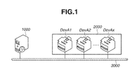
- FIG. 1 illustrates an example of a network configuration according to a first exemplary embodiment of the present invention.
- This network system includes a management apparatus 1000 and network devices 2000 (DevA 1 to DevAx).
- the management apparatus 1000 and the network devices 2000 are connected with each other via a communication line 3000 .
- the network devices 2000 include image formation apparatuses such as printers, copying machines, and scanners, and network connection apparatuses such as network cameras, mobile phones, and car navigation systems.
- the communication line 3000 achieves a wired or wireless network connection.
- the network connection is not limited to a local area network, and may be the Internet environment.
- the management apparatus 1000 is a server in which a device management unit 30 for managing the network devices 2000 illustrated in FIG. 3 operates, and may be implemented as a web service server. More specifically, a device management application executed by the management apparatus 1000 will operate as a web application. In this case, a user of a client apparatus (not illustrated) accesses a web service server (management apparatus 1000 ) by using a web browser operating on the client apparatus on the communication line 3000 to perform operations related to network device management processing. More specifically, the web browser displays a management screen (described below) provided by the management apparatus 1000 , and the user operates the relevant management screen. Thus, the network devices management processing is performed by the management apparatus 1000 .
- FIG. 2 illustrates an example of a hardware configuration of the management apparatus 1000 .
- a central processing unit (CPU) 10 executes various programs stored in a read only memory (ROM) 11 and a hard disk drive (HDD) 19 by using a random access memory (RAM) 12 as a work area.
- the device management unit 30 (described below) is also one of functions implemented when the CPU 10 executes one or more programs (device management application).
- the device management application is supplied via a storage medium, such as a floppy disk (FD), a compact disc read only memory (CD-ROM), a digital versatile disc (DVD), a magnetic tape, and an integrated circuit (IC) memory card which can be mounted on disk drive 20 .
- the CPU 10 displays a user interface on a display apparatus (such as a cathode ray tube (CRT)) 15 via a video card (VC) 14 .
- the CPU 10 further performs control according to an instruction through the user interface input from a keyboard (KB) 17 via a keyboard controller (KBC) 16 .
- KBC keyboard controller
- instructions can be input by using a pointing device such as a mouse (not illustrated), and a touch panel.
- the CPU 10 executes data communication with the network devices 2000 on the communication line 3000 via a network interface board (NIC) 21 .
- NIC network interface board
- FIG. 3 illustrates an example of a software module configuration of the management apparatus 1000 . More specifically, FIG. 3 illustrates an example of a virtual module configuration to illustrate functions implemented by executing programs according to the present exemplary embodiment.
- the device management unit 30 includes a framework unit 40 and one or more plug-in units 50 .
- the management apparatus 1000 includes a data storage unit 31 which is shared by the framework unit 40 and the plug-in unit 50 . Storage areas, such as the HDD 19 , are used as the data storage unit 31 .
- the framework unit 40 includes a plug-in management unit 41 , a device control unit 42 , a task management unit 43 , and a transmission unit 44 .
- the plug-in management unit 41 manages the addition and deletion of functions (services) to/from the device management application by plug-in programs.
- a function (service) is added by the relevant plug-in program, the plug-in unit 50 illustrated in FIG. 3 will be added.
- the plug-in management unit 41 Upon reception of an instruction for deleting a plug-in program from a user (network administrator) of the management apparatus 1000 , the plug-in management unit 41 manages the deletion, activation, and deactivation of the plug-in unit 50 .
- the device control unit 42 controls the function of searching for a network device 2000 on the network, and the function of acquiring device information. In connection with these functions, the device control unit 42 can register a search task and a monitoring task in the data storage unit 31 as a type of remote tasks, and executes these tasks.
- Function information includes identification information (such as the Internet Protocol (IP) address), status information, function information, device configuration information of the network devices 2000 .
- IP Internet Protocol
- the device control unit 42 acquires the function information by using messages conforming to various network protocols. For example, the device control unit 42 acquires Management Information Base (MIB) information as device information.
- MIB Management Information Base
- the task management unit 43 controls the management and execution of remote tasks generated and registered in the data storage unit 31 by the device control unit 42 .
- the task management unit 43 also performs display control of the display apparatus, such as display of management screens for changing and deleting remote tasks and display of execution results.
- the transmission unit 44 makes an update notification to the plug-in unit 50 according to the result of remote task execution.
- the plug-in unit 50 includes a plug-in control unit 51 , a plug-in task management unit 52 , and a reception unit 53 .
- plug-in units 50 Examples of functions added to the device management application as the plug-in units 50 will be described below. These functions may be implemented as one plug-in unit 50 . Further, plug-in programs may be configured so that these functions are implemented by one or more plug-in units 50 .
- Remote tasks generated by the above-described functions (1) to (3) based on the plug-in units 50 are referred to as regular tasks.
- a remote task generated by the function (4) is referred to as a one-shot task in the present exemplary embodiment.
- a remote task for an authentication test on the network devices 2000 which is an example of a one-shot task
- operations on a screen provided by the management apparatus are locked since the time when the user presses a button on the screen until the time when it becomes possible to determine and make a notification of the execution result of the task.
- This aims to prevent the user from operating or executing other management functions until the authentication test is successfully completed.
- a timeout function is enabled on the assumption of a case where the result cannot be determined because of a network failure. If a predetermined time period has elapsed since the user presses the relevant button, the timeout function cancels the one-shot task currently being executed.
- a task for executing a communication test on a web service for managing the firmware of the network devices 2000 there is a task for executing a communication test on a web service for managing the firmware of the network devices 2000 .
- This type of task is a remote task generated by the plug-in unit 50 having at least the function (1). During execution of this remote task, operations on the relevant screen are locked until it becomes possible to determine and make a notification of the result of the communication test.
- the web service for managing the firmware may be implemented as a function of a server apparatus on the network different from the management apparatus 1000 , or provided in the management apparatus 1000 .
- the plug-in unit 50 generates a special remote task for executing regular tasks related to the above-described functions (1) to (3).
- This special remote task is a task (hereinafter referred to as a sub search task) for investigating whether the network devices 2000 subjected to management by the device management unit 30 are provided with functions corresponding to these regular tasks. For example, upon reception of an instruction for updating the firmware, a sub search task for regular tasks related to the function (1) is generated and executed to determine whether a network device 2000 is provided with a function of applying the relevant firmware (device application). When a specific condition is satisfied, a sub search task is generated and executed by the plug-in unit 50 in the background without an instruction input from the user.
- a sub search task is generated and executed by the plug-in unit 50 in the background.
- a sub search task is generated and executed by the plug-in unit 50 in the background.
- remote tasks for achieving the management of the network devices 2000 include sub search tasks and one-shot tasks which are auxiliary tasks for reliably executing regular tasks.
- the reception unit 53 Upon reception of an update notification from the transmission unit 44 of the framework unit 40 , the reception unit 53 internally instructs the plug-in task management unit 52 to execute a task.
- update notifications include a notification that a new network device 2000 is found and a notification about change in the device configuration information of a management target network device 2000 .
- the reception unit 53 instructs the plug-in task management unit 52 to generate and execute a sub search task.
- the plug-in task management unit 52 controls execution of regular tasks and one-shot tasks specified to be executed by the plug-in control unit 51 , and controls execution of sub search tasks specified to be executed by the reception unit 53 .
- Remote tasks specified to be executed are once registered in the data storage unit 31 and sequentially executed.
- the plug-in task management unit 52 determines the execution priority of these remote tasks according to the task attribute of each of the registered remote tasks.
- FIG. 4 illustrates an example of device information for each of the network devices 2000 (DevA 1 to DevAx).
- the device information includes the device name, the product name, the address information, the operating condition, and supported services.
- a network device DevA 1 has device name “DevA 1 ”, product name “DevA”, and address information “IP_A 1 ”.
- the network device DevA 1 has operating condition “OPERATING”, and supports services “sPIA to sPIX”.
- the address information is, for example, the IP address for enabling communication with the framework unit 40 and the plug-in unit 50 of the device management unit 30 .
- supported services indicate function information for supporting each function provided by the plug-in unit 50 .
- the service “sPIA” is a service for supporting the function of the plug-in A having the plug-in unit 50 . This service may be provided as a function to be implemented by installing a device application in a network device 2000 .
- FIG. 5 is a table (device list) storing execution results of remote tasks generated and executed by the device control unit 42 of the framework unit 40 .
- the executed remote tasks include the above-described search tasks and monitoring tasks.
- the device information to be stored in the table illustrated in FIG. 5 includes the device name, the product name, the address information, and the operating condition.
- device information acquired from the network device DevA 1 through task execution includes device name “DevA 1 ”, product name “DevA”, address information “IP_A 1 ”, and operating condition “OPERATING”.
- the device information illustrated in FIG. 5 may be implemented not only by executing remote tasks but also by importing a file storing these pieces of information to the device management unit 30 .
- the device control unit 42 is provided with a function of determining whether to instruct the transmission unit 44 to transmit an update notification, based on a predetermined condition. As described above, when a new network device 2000 is found as a result of network search or when information about the management target network device 2000 is specified to be deleted, the device control unit 42 of the framework unit 40 instructs the transmission unit 44 to transmit an update notification. It is possible to set other conditions under which the device control unit 42 instructs the transmission unit 44 to transmit an update notification. Examples of other conditions are:
- a new network device 2000 is added by importing a file to the device management unit 30 .
- the device configuration information of an existing management target network device 2000 is changed.
- the plug-in management unit 41 detects the addition of a new plug-in unit 50 .
- the above-described conditions may be set by the user using one of device management screens provided as functions of the framework unit 40 , or by reading conditions defined in an external file referable to by the device control unit 42 .
- a sub search task is a remote task for determining whether a network device 2000 supports the function provided by the plug-in unit 50 . Therefore, it is desirable that the plug-in unit 50 executes sub search tasks before executing regular tasks and one-shot tasks.
- Sub search tasks are generated for the number of network devices 2000 registered in the device list in the table illustrated in FIG. 5 . In other words, the number of generated sub search tasks and the generation timing thereof are determined depending on the framework unit 40 .
- a device authentication task is a remote task for performing in advance the device authentication required to execute regular tasks.
- a sub search task will perform the device authentication on network devices 2000 determined to support the functions provided by the plug-in unit 50 .
- setting of the device authentication information can be omitted when the regular tasks are generated afterwards.
- Regular tasks can be generated and executed by using execution results of not only sub search tasks but also one-shot tasks. Therefore, it is desirable to set a lower task execution priority to regular tasks than task execution priorities set to sub search tasks and one-shot tasks.
- the priority of each of these tasks at the time of task execution control is determined in consideration of the characteristics of each of these tasks. More specifically, one-shot tasks are determined to have the “High” priority, sub search tasks are determined to have the “Middle” priority, and, regular tasks are determined to have the “Low” priority.
- FIGS. 6A and 6B illustrate an example of task execution control by the plug-in task management unit 52 of the plug-in unit 50 .
- a plurality of remote tasks registered in the data storage unit 31 by the plug-in task management unit 52 is managed by using the execution waiting task queue and the executing task queue.
- Remote tasks stored in the executing task queue indicate that they are currently being executed on the network devices 2000 .
- the maximum number of tasks storable in the executing task queue is assumed to be 5. This means that up to 5 tasks can be executed in parallel by the plug-in unit 50 .
- the tasks in the execution waiting task queue are sequentially stored in the executing task queue, starting from the first task.
- the execution waiting task queue manages regular tasks having the “Low” priority corresponding to the network devices DevA 1 to DevAx and sub search tasks having the “Middle” priority corresponding to the network devices DevA 6 to DevAx. Further, sub search tasks for the network devices DevA 1 to DevA 5 are currently being executed in the executing task queue.
- the plug-in task management unit 52 is instructed to execute two one-shot tasks for network devices DevAn and DevAm by the plug-in control unit 51 .
- the plug-in task management unit 52 will determine the “High” priority about these one-shot tasks.
- the plug-in task management unit 52 queues two one-shot tasks into the execution waiting task queue so that they are executed in preference to the sub search tasks already managed in the execution waiting task queue. With this processing, the two one-shot tasks will be stored in the executing task queue and executed in preference to the existing sub search tasks in the execution waiting queue.
- FIG. 7 illustrates various cases in which the plug-in task management unit 52 queues a new remote task into the execution waiting task queue.
- the leftmost column indicates remote tasks already managed in the execution waiting task queue by the plug-in task management unit 52 , and priorities of the remote tasks.
- the top row indicates a new remote task that the plug-in task management unit 52 is newly instructed to execute, and the priority of the new remote task.
- FIGS. 6A and 6B indicates a case where the plug-in task management unit 52 is instructed to execute the task D as a new task in the state of the 4th row illustrated in FIG. 7 .
- FIG. 7 illustrates that the task D is queued before the existing execution waiting tasks.
- the plug-in task management unit 52 when the plug-in task management unit 52 is instructed to execute the task D as a new task in the state of the 1st row, the task D is queued into the execution waiting task queue so as to be executed after the existing task A having the “High” priority.
- FIG. 8A illustrates an example of a plug-in list stored in the data storage unit 31 by the plug-in management unit 41 .
- the table illustrated in FIG. 8A includes status information of each plug-in, such as the plug-in name, the version, and the operating condition. For example, the table illustrates that the plug-in having plug-in name “PLUG-IN A” and version “v1.0.0” is operating. On the other hand, the plug-in having plug-in name “PLUG-IN B” and version “v2.1.0” is stopped.
- FIGS. 9A and 9B illustrate examples of management screens provided by the device management unit 30 implemented by the device management application.
- a management screen 60 includes a menu 61 and a task generation area 62 .
- the device management unit 30 performs control to display a task generation screen in the task generation area 62 according to the menu 61 selected by the user via the management screen 60 .
- FIG. 9A illustrates a screen configuration in a case where the device management unit 30 includes only the framework unit 40 .
- the menu 61 in this case includes “DEVICE MANAGEMENT TASK” for managing remote tasks in terms of the search function and the monitoring function provided by the framework unit 40 , and “PLUG-IN MANAGEMENT” for managing the addition of plug-in programs.
- DEVICE MANAGEMENT TASK a regular task for searching for and monitoring network devices 2000 can be generated.
- the “PLUG-IN MANAGEMENT” menu is selected, operations for adding, deleting, and activating/deactivating plug-ins can be specified.
- FIG. 9B illustrates an example of a screen configuration when plug-ins A to X are added as the plug-in units 50 .
- menu items for using the functions of the plug-in unit 50 of the plug-ins A to X are added.
- the plug-in A when the “DEVICE AUTHENTICATION INFORMATION TASK” menu is selected, operations related to the generation of a device authentication task (one-shot task) can be performed. Further, the “REGULAR TASK OF PLUG-IN A” menu for generating a regular task specific to the plug-in A is also prepared.
- the plug-in control unit 51 acquires a support device list illustrated in FIG. 11 stored in the data storage unit 31 .
- the plug-in control unit 51 further performs control to display a device authentication information setting screen in the task generation area 62 on the display apparatus.
- FIG. 11 illustrates an example of a list of network devices 2000 (support device list) supporting the function provided by each plug-in program managed in the data storage unit 31 by the plug-in control unit 51 of each plug-in unit 50 .
- the support device list includes device information, such as the device name, the product name, and the address information.
- the support device list is suitably updated by the plug-in control unit 51 according to the execution results of sub search tasks.
- FIG. 12 illustrates an example of a device authentication information setting screen. This setting screen provides device information, authentication information, and authentication test information.
- the “AUTHENTICATION INFORMATION” display portion includes columns “AUTHENTICATION METHOD”, “DOMAIN NAME”, “USER NAME”, and “PASSWORD” to enable setting and editing the authentication information.
- the “AUTHENTICATION TEST” display portion includes an “AUTHENTICATE” button for executing the authentication test, and column “RESULT” for displaying the execution result.
- the authentication information set on this screen is information about authentication with an apparatus to be processed by remote tasks, to make successful regular tasks provided by each plug-in. This authentication information is preset in the network devices 2000 as target apparatuses.
- the “DOMAIN AUTHENTICATION” method requires a domain name, a user name, and a password in authentication with network devices 2000 .
- the “LOCAL DEVICE AUTHENTICATION” method requires a user name and a password.
- the authentication method is not limited to “DOMAIN AUTHENTICATION” and “LOCAL DEVICE AUTHENTICATION”.
- the authentication method supported by apparatuses to be processed by remote tasks, such as the network devices 2000 can be flexibly set via the setting screen.
- the setting screen illustrated in FIG. 12 includes an “UPDATE” button for storing set and edited authentication information, and a “CANCEL” button for cancelling setting processing.
- the “DOMAIN AUTHENTICATION” method, domain name “DomainA”, user name “UserA1”, and password “123” are set by the user as the authentication information for the network device DevA 1 .
- the password is displayed as “000” to protect privacy.
- the plug-in control unit 51 instructs the plug-in task management unit 52 to execute the device authentication task. In this case, the screen itself is locked to prohibit user operations on the setting screen illustrated in FIG. 12 .
- the plug-in control unit 51 When the plug-in control unit 51 is notified of the result of task execution by the plug-in task management unit 52 , the plug-in control unit 51 displays the result of one-shot task execution in column “RESULT” for “AUTHENTICATION TEST” illustrated in FIG. 12 .
- FIG. 13 illustrates an example of a device authentication information list stored in the data storage unit 31 .
- device information such as the device name and the product name, and authentication information such as the authentication method, the domain name, the user name, and the password corresponding to the device information, is managed.
- the device control unit 51 refers to the lists illustrated in FIGS. 11 and 13 .
- the plug-in task management unit 52 is instructed to execute a device authentication task which is a one-shot task. Processing performed by the plug-in task management unit 52 according to this operation will be described in detail below with reference to FIG. 15 .
- FIG. 10A illustrates an example of a plug-in management screen displayed in the task generation area 62 when the “PLUG-IN MANAGEMENT” menu is selected.
- the plug-in management unit 41 acquires the plug-in list illustrated in FIG. 8A stored in the data storage unit 31 , and performs control to display the plug-in list in the task generation area 62 .
- the “PLUG-IN MANAGEMENT” screen includes columns “PLUG-IN NAME”, “VERSION”, and “PLUG-IN STATUS” relating to added plug-in units 50 .
- the “PLUG-IN MANAGEMENT” screen also displays at least one of a “STOP” button and a “START” button as an instruction portion for controlling the plug-in status, and displays a “DELETE” button for instructing to delete the stopped plug-in unit 50 .
- the “PLUG-IN MANAGEMENT” screen also displays an “ADD PLUG-IN” button for displaying a screen for adding a new plug-in program and an “END” button for ending the operation on the “PLUG-IN MANAGEMENT” screen.
- the “ADD PLUG-IN” screen illustrated in FIG. 10B is displayed.
- the “ADD PLUG-IN” screen displays an edit box for specifying a path and a file in which a plug-in program is stored.
- the “ADD PLUG-IN” screen further displays an “ADD” button for instructing to add a plug-in and a “CANCEL” button for canceling the processing.
- the information about the plug-in program specified to be added will be newly stored in the data storage unit 31 by the plug-in management unit 41 .
- the plug-in management unit 41 Upon reception of a sub search task execution end notification from the plug-in task management unit 52 of the plug-in unit 50 corresponding to the added plug-in program, the plug-in management unit 41 updates the information about the “PLUG-IN MANAGEMENT” screen and displays the “PLUG-IN MANAGEMENT” screen including a plug-in Y.
- FIG. 14 is a flowchart illustrating processing performed by the plug-in management unit 41 and the plug-in task management unit 52 .
- step S 100 upon reception of an operation for adding a specified plug-in program (plug-in unit 50 ), the plug-in management unit 41 performs addition processing.
- step S 101 the plug-in management unit 41 acquires a device list of monitoring target network devices 2000 stored in the data storage unit 31 . Referring to the examples illustrated in FIGS. 10A and 10B , after the “ADD” button for the plug-in Y illustrated in FIG. 10B is pressed, the plug-in management unit 41 will acquire the device list illustrated in FIG. 5 from the data storage unit 31 .
- step S 102 the plug-in management unit 41 determines whether a target network device 2000 exists in the acquired device list.
- the processing proceeds to step S 103 .
- the processing is terminated.
- step S 103 the plug-in management unit 41 transmits an update notification according to the addition of a plug-in to the reception unit 53 of the added plug-in unit 50 via the transmission unit 44 .
- the plug-in management unit 41 transmits an update notification to the reception unit 53 of the added plug-in unit 50 to execute sub search tasks for X network devices 2000 (DevA 1 to DevAx). Update notifications for the number of devices including the device information illustrated in FIG. 5 may be transmitted.
- the plug-in unit 50 generates a sub search task for each target network device 2000 .
- step S 104 the reception unit 53 of the plug-in unit 50 instructs the plug-in task management unit 52 to generate and execute a sub search task according to the received update notification.
- step S 105 the plug-in task management unit 52 registers the generated sub search tasks for X network devices 2000 in the execution waiting task queue managed by the plug-in task management unit 52 . Processing performed in step S 105 will be described in detail below with reference to FIG. 15 .
- step S 106 the plug-in task management unit 52 sequentially moves remote tasks in the execution waiting task queue illustrated in FIGS. 6A and 6B to the executing task queue, and executes the remote tasks.
- X sub search tasks corresponding to the X network devices 2000 are sequentially executed.
- step S 107 the plug-in task management unit 52 executes the task end processing according to the execution result of each remote task executed in step S 106 . Processing performed in step S 107 will be described in detail below with reference to FIG. 17 .
- the plug-in management unit 41 stores the plug-in information of the plug-in unit 50 added to the plug-in list in the data storage unit 31 . With this operation, the plug-in program addition processing ends.
- FIG. 15 is a flowchart illustrating in detail the processing performed by the plug-in task management unit 52 in step S 105 .
- This processing is performed not only in a case of plug-in addition as illustrated in FIG. 15 but also in a case of an operation for executing one-shot tasks and regular tasks via a management screen provided by the existing plug-in unit 50 , and in a case where sub search tasks are specified to be executed under other conditions.
- the plug-in task management unit 52 analyzes the attribute of the remote task specified to be executed. More specifically, the plug-in task management unit 52 refers to the attribute of the remote task specified to be executed, and analyzes that the instruction source is the reception unit 53 and that the relevant remote task is not a remote task generated through an operation via a menu such as a management screen provided by the plug-in unit 50 .
- the attribute of the remote task enables analyzing the information about the instruction source of execution.
- the attribute of the remote task also enables analyzing whether the relevant remote task was generated through an operation via a menu such as a management screen provided by the plug-in unit 50 , and whether the relevant remote task is a remote task during which management screen operations are locked and the timeout processing is performed according to an execution instruction.
- the above-described analysis by the plug-in task management unit 52 is used to determine the priority of the remote task specified to be executed. However, it is also possible that, instead of setting such an attribute to the remote task, the priority is set to the remote task to be analyzed by the plug-in task management unit 52 .
- step S 202 the plug-in task management unit 52 acquires information about the remote tasks stored in the execution waiting task queue illustrated in FIGS. 6A and 6B . More specifically, the plug-in task management unit 52 acquires information about whether remote tasks are stored in the execution waiting task queue on a priority basis. In the example illustrated in FIG. 10B , since the plug-in task management unit 52 acquires information of the execution waiting task queue in relation to the plug-in Y which has been newly added, the plug-in task management unit 52 can determine that no remote task has been stored in the execution waiting task queue.
- step S 203 the plug-in task management unit 52 determines the priority of the remote task specified to be executed.
- the processing proceeds to step S 204 .
- the priority is determined to be “Middle” (Middle in step S 203 )
- the processing proceeds to step S 206 .
- the priority is determined to be “Low” (Low in step S 203 )
- the processing proceeds to step S 211 .
- the priority is determined to be “High” in step S 203 , and the processing proceeds to step S 204 .
- the example illustrated in FIG. 10B indicates a case where the plug-in task management unit 52 is instructed to execute a sub search task accompanying the addition of the plug-in Y. In this case, the priority is determined to be “Middle” in step S 203 , and the processing proceeds to step S 206 .
- step S 204 the plug-in task management unit 52 determines whether a remote task having the “High” priority exists in the remote tasks stored in the execution waiting task queue acquired in step S 202 .
- the processing proceeds to step S 208 .
- the processing proceeds to step S 205 .
- step S 205 the plug-in task management unit 52 additionally registers the remote task presently specified to be executed at the top of the execution waiting task queue. When remote tasks having the “Middle” and “Low” priorities are stored in the execution waiting task queue, the remote task presently specified to be executed will be additionally registered before these tasks.
- step S 208 the plug-in task management unit 52 identifies a remote task stored in the execution waiting task queue and registered as the last remote task having the same priority as the remote task presently specified to be executed, and then additionally registers the remote task presently specified to be executed so that it is to be executed next thereto. For example, assume a case where the remote task presently specified to be executed has the “High” priority, and remote tasks having the “High”, “Middle”, and “Low” priorities exist in the execution waiting task queue. In that case, the remote task presently specified to be executed will be additionally registered between the stored remote tasks having the “Middle” and “Low” priorities and the stored remote task having the “High” priority.
- step S 206 the plug-in task management unit 52 determines whether a task having the “Middle” priority or higher exists in the remote tasks stored in the execution waiting task queue acquired in step S 202 .
- the processing proceeds to step S 207 .
- the processing proceeds to step S 210 .
- step S 207 the plug-in task management unit 52 determines whether a remote task having the “Middle” priority exists in the remote tasks stored in the execution waiting task queue acquired in step S 202 .
- the processing proceeds to step S 208 .
- the processing proceeds to step S 209 .
- step S 209 the plug-in task management unit 52 identifies a remote task stored in the execution waiting task queue and registered as the last remote task having a higher priority than the remote task presently specified to be executed, and then additionally registers the remote task presently specified to be executed so that it is to be executed next thereto.
- step S 210 the plug-in task management unit 52 additionally registers the remote task presently specified to be executed at the top of the execution waiting task queue.
- the remote task presently specified to be executed will be additionally registered before these tasks.
- the plug-in task management unit 52 registers at the top of the empty execution waiting task queue a sub search task targeting the first network device 2000 .
- step S 211 the plug-in task management unit 52 additionally registers, at the end of the execution waiting task queue, the remote task presently specified to be executed. This processing is performed when a regular task is specified to be executed by the plug-in control unit 51 .
- FIG. 17 is a flowchart illustrating details of remote task end processing in step S 107 performed by the plug-in task management unit 52 .
- This processing is performed not only in a case of plug-in addition as illustrated in FIG. 15 but also in a case of an operation for executing one-shot tasks and regular tasks via a management screen provided by the existing plug-in unit 50 , and in a case where sub search tasks are specified to be executed under other conditions.
- step S 300 the plug-in task management unit 52 analyzes the device information of the network device 2000 to be processed by the remote task executed in step S 106 , the success or failure of the remote task, and the task attribute of the executed remote task.
- the plug-in task management unit 52 refers to the device information acquired from the target network device 2000 and information about whether the service “sPIY” supported by the plug-in Y is operating. When the service “sPIY” is operating, the plug-in task management unit 52 analyzes that the sub search task is successfully executed.
- step S 301 the plug-in task management unit 52 determines the type of the executed remote task.
- the processing proceeds to step S 302 .
- the processing proceeds to step S 307 .
- the processing proceeds to step S 309 .
- step S 302 the plug-in task management unit 52 determines whether the network device 2000 to be processed by the sub search task is a support device of which the supported service is operating.
- the processing proceeds to step S 303 .
- the processing proceeds to step S 304 .
- step S 303 the plug-in task management unit 52 requests the plug-in control unit 51 to register in the support device list in the data storage unit 31 ( FIG. 11 ) the device information of the network device 2000 to be processed by the sub search task.
- step S 304 the plug-in task management unit 52 requests the plug-in control unit 51 to delete from the support device list in the data storage unit 31 ( FIG. 11 ) the device information of the network device 2000 to be processed by the sub search task.
- step S 305 the plug-in task management unit 52 determines whether the device authentication information of the network device 2000 to be processed by the sub search task exists in the device authentication information list in the data storage unit 31 ( FIG. 13 ). When the relevant device authentication information is determined to exist (YES in step S 305 ), the processing proceeds to step S 306 . On the other hand, when the relevant device authentication information is determined not to exist (NO in step S 305 ), the processing proceeds to step S 309 . In step S 306 , the plug-in task management unit 52 requests the plug-in control unit 51 to delete the relevant device authentication information from the device authentication information list.
- step S 307 the plug-in task management unit 52 determines whether the one-shot task is successful or failed.
- the one-shot task is determined to be successful when authentication processing with the network device 2000 to be processed by the relevant device authentication task is successfully executed.
- the processing proceeds to step S 308 .
- the plug-in task management unit 52 requests the plug-in control unit 51 to register, in the data storage unit 31 , the information confirmed through the success of the one-shot task.
- the plug-in control unit 51 will register, in the device authentication information list in the data storage unit 31 ( FIG. 13 ), the authentication information of the network device 2000 to be processed by the relevant device authentication task and the device information used for task execution.
- step S 309 the plug-in task management unit 52 notifies the plug-in management unit 41 of the completion of the remote task end processing together with information about the success or failure of the relevant task. For example, when the device authentication task is analyzed to be successful as a one-shot task, “OK” is displayed in the “RESULT” column of “AUTHENTICATION TEST” in the setting screen illustrated in FIG. 12 . Accordingly, operations on the management screen are unlocked.
- a second exemplary embodiment includes further improved example of processing than the processing illustrated in FIG. 17 .
- the present exemplary embodiment premises that the device authentication information used in a certain plug-in unit 50 can be utilized by a plurality of other plug-in units 50 . Further, it is also premised that some plug-in units 50 have a device authentication function and others do not.
- the plug-in control unit 51 deletes the device authentication information stored in relation to a network device 2000 determined not to be a support device.
- the relevant device authentication information may be used by the relevant another plug-in unit 50 , and it is not necessary to delete it.
- FIG. 18 illustrates a modification of the processing illustrated in FIG. 17 taking the above-described premise into consideration.
- the flowchart illustrated in FIG. 18 differs from the flowchart in FIG. 17 in that steps S 400 and S 401 are added thereto. For the processing already described with reference to FIG. 17 , redundant description will be omitted.
- step S 400 the plug-in task management unit 52 acquires the plug-in list in the data storage unit 31 illustrated in FIG. 8B .
- FIG. 8B illustrates an example of a plug-in list stored in the data storage unit 31 by the plug-in management unit 41 .
- This list includes item columns for each plug-in such as “PLUG-IN NAME”, “VERSION”, “PLUG-IN STATUS” indicating the operating condition, and “DEVICE AUTHENTICATION” indicating whether the device authentication function is supported.
- the plug-in A has plug-in name “PLUG-IN A”, version “v1.0.0”, and operating condition “OPERATING”, and supports the device authentication function.
- the plug-in supporting the device authentication function has a “DEVICE AUTHENTICATION INFORMATION TASK” menu as one of menus, as illustrated in FIG. 9B .
- step S 401 the plug-in task management unit 52 determines whether a plug-in having the device authentication function exists in the plug-in list acquired in step S 400 .
- the processing proceeds to step S 309 .
- the processing proceeds to step S 306 .
- step S 306 the plug-in task management unit 52 will delete the relevant device authentication information from the device authentication information list.
- the device authentication information of the network device 2000 identified to be not a support device by the sub search task will be deleted.
- a third exemplary embodiment includes a further improved example of processing than the processing illustrated in FIG. 15 .
- the sub search task is executed and the target network device 2000 no longer is a support device.
- the supported service is stopped or not installed although the authentication information has been set to the target network device 2000 .
- the device authentication task of a network device 2000 which is not a support target will be executed, which is not necessary at least for the relevant plug-in unit 50 . This may lead the plug-in control unit 51 to register unnecessary information in the device authentication information list in the data storage unit 31 ( FIG. 13 ).
- the plug-in task management unit 52 when the plug-in task management unit 52 is instructed to execute a one-shot task while a sub search task having the same processing target is waiting in the execution waiting task queue, it is desirable to control execution of the one-shot task based on the execution result of the sub search task.
- the device authentication information is shared and used by a plurality of plug-in units 50 , it may not be useless even if a one-shot task is executed before a sub search task.
- FIG. 16 illustrates a modification of the processing illustrated in FIG. 15 taking the above-described case into consideration.
- the flowchart illustrated in FIG. 16 differs from the flowchart in FIG. 15 in that steps S 500 to S 502 are added thereto.
- steps S 500 to S 502 are added thereto.
- redundant description will be omitted.
- step S 500 the plug-in task management unit 52 acquires the plug-in list illustrated in FIG. 8A in the data storage unit 31 .
- step S 501 the plug-in task management unit 52 determines whether any other plug-in units 50 exist in the plug-in list acquired in step S 500 . When any other plug-ins are determined not to exist (NO in step S 501 ), the processing proceeds to step S 502 . On the other hand, when any other plug-ins are determined to exist (YES in step S 501 ), the processing proceeds to step S 204 .
- step S 502 the plug-in task management unit 52 determines whether a sub search task targeting the network device 2000 to be processed by the remote task having the “High” priority already exists in the execution waiting task queue illustrated in FIGS. 6A and 6B .
- the processing proceeds to step S 503 .
- the processing proceeds to step S 204 .
- step S 503 the plug-in task management unit 52 generates a connection task having the “High” priority for connecting the remote task having the “High” priority and the relevant sub search task.
- This connection task is a task for continuously executing the remote task having the “High” priority and the relevant sub search task on the same network device 2000 .
- the relevant sub search task registered in the execution waiting task queue is deleted.
- the device authentication task for the target network device 2000 is canceled.
- processing is continued for this connection task.
- Control according to the present exemplary embodiment enables preventing useless one-shot task execution.
- Embodiments of the present invention can also be realized by a computer of a system or apparatus that reads out and executes computer executable instructions recorded on a storage medium (e.g., non-transitory computer-readable storage medium) to perform the functions of one or more of the above-described embodiment(s) of the present invention, and by a method performed by the computer of the system or apparatus by, for example, reading out and executing the computer executable instructions from the storage medium to perform the functions of one or more of the above-described embodiment(s).
- the computer may comprise one or more of a central processing unit (CPU), micro processing unit (MPU), or other circuitry, and may include a network of separate computers or separate computer processors.
- the computer executable instructions may be provided to the computer, for example, from a network or the storage medium.
- the storage medium may include, for example, one or more of a hard disk, a random-access memory (RAM), a read only memory (ROM), a storage of distributed computing systems, an optical disk (such as a compact disc (CD), digital versatile disc (DVD), or Blu-ray Disc (BD)TM), a flash memory device, a memory card, and the like.
Applications Claiming Priority (2)
| Application Number | Priority Date | Filing Date | Title |
|---|---|---|---|
| JP2013-257162 | 2013-12-12 | ||
| JP2013257162A JP6214372B2 (ja) | 2013-12-12 | 2013-12-12 | 管理装置、その方法及びプログラム |
Publications (2)
| Publication Number | Publication Date |
|---|---|
| US20150172133A1 US20150172133A1 (en) | 2015-06-18 |
| US9838270B2 true US9838270B2 (en) | 2017-12-05 |
Family
ID=53192935
Family Applications (1)
| Application Number | Title | Priority Date | Filing Date |
|---|---|---|---|
| US14/566,437 Active 2035-08-17 US9838270B2 (en) | 2013-12-12 | 2014-12-10 | Management apparatus and management method for management apparatus |
Country Status (3)
| Country | Link |
|---|---|
| US (1) | US9838270B2 (ja) |
| JP (1) | JP6214372B2 (ja) |
| DE (1) | DE102014225538A1 (ja) |
Cited By (1)
| Publication number | Priority date | Publication date | Assignee | Title |
|---|---|---|---|---|
| US20220342677A1 (en) * | 2020-05-22 | 2022-10-27 | Boe Technology Group Co., Ltd. | Processing Method and Apparatus of Device Status Change and Non-Transitory Computer-Readable Storage Medium |
Families Citing this family (6)
| Publication number | Priority date | Publication date | Assignee | Title |
|---|---|---|---|---|
| JP6508479B2 (ja) * | 2015-11-30 | 2019-05-08 | 京セラドキュメントソリューションズ株式会社 | 実行制御機器、実行制御プログラムおよびタスク実行システム |
| US20180068345A1 (en) * | 2016-09-08 | 2018-03-08 | Tatsuma HIROKAWA | Information processing apparatus, method of processing information, and storage medium |
| JP7039318B2 (ja) | 2018-02-20 | 2022-03-22 | キヤノン株式会社 | 管理装置及び方法 |
| JP7360086B2 (ja) | 2019-09-27 | 2023-10-12 | 京セラドキュメントソリューションズ株式会社 | 遠隔操作システム、管理クライアントおよび管理クライアントプログラム |
| US11347566B2 (en) * | 2020-02-06 | 2022-05-31 | Dell Products, L.P. | Adaptive runtime prioritization for component plugins |
| CN115174342B (zh) * | 2022-06-15 | 2024-03-08 | 阿里巴巴(中国)有限公司 | 网关的插件管理方法、装置及设备 |
Citations (5)
| Publication number | Priority date | Publication date | Assignee | Title |
|---|---|---|---|---|
| US20060279773A1 (en) * | 2005-06-10 | 2006-12-14 | Canon Kabushiki Kaisha | Information processing apparatus and control method therefor |
| US20090070442A1 (en) * | 2007-09-07 | 2009-03-12 | Kace Networks, Inc. | Architecture And Protocol For Extensible And Scalable Communication |
| JP2009151467A (ja) | 2007-12-19 | 2009-07-09 | Canon Inc | 配信印刷システム |
| US20130212591A1 (en) * | 2006-03-15 | 2013-08-15 | Mihai-Daniel Fecioru | Task scheduling method and apparatus |
| US20140331230A1 (en) * | 2013-05-01 | 2014-11-06 | Advanced Micro Devices, Inc. | Remote Task Queuing by Networked Computing Devices |
Family Cites Families (3)
| Publication number | Priority date | Publication date | Assignee | Title |
|---|---|---|---|---|
| JP2000066904A (ja) * | 1998-08-21 | 2000-03-03 | Canon Inc | マルチタスク制御方法及び記憶媒体 |
| JP2006065388A (ja) * | 2004-08-24 | 2006-03-09 | Canon Inc | 情報処理装置、アプリケーションインストール方法、及びプログラム |
| JP2013172240A (ja) * | 2012-02-20 | 2013-09-02 | Seiko Epson Corp | 電子機器の機能制限解除システム、電子機器の機能制限解除方法及び電子機器 |
-
2013
- 2013-12-12 JP JP2013257162A patent/JP6214372B2/ja active Active
-
2014
- 2014-12-10 US US14/566,437 patent/US9838270B2/en active Active
- 2014-12-11 DE DE102014225538.4A patent/DE102014225538A1/de active Pending
Patent Citations (5)
| Publication number | Priority date | Publication date | Assignee | Title |
|---|---|---|---|---|
| US20060279773A1 (en) * | 2005-06-10 | 2006-12-14 | Canon Kabushiki Kaisha | Information processing apparatus and control method therefor |
| US20130212591A1 (en) * | 2006-03-15 | 2013-08-15 | Mihai-Daniel Fecioru | Task scheduling method and apparatus |
| US20090070442A1 (en) * | 2007-09-07 | 2009-03-12 | Kace Networks, Inc. | Architecture And Protocol For Extensible And Scalable Communication |
| JP2009151467A (ja) | 2007-12-19 | 2009-07-09 | Canon Inc | 配信印刷システム |
| US20140331230A1 (en) * | 2013-05-01 | 2014-11-06 | Advanced Micro Devices, Inc. | Remote Task Queuing by Networked Computing Devices |
Cited By (2)
| Publication number | Priority date | Publication date | Assignee | Title |
|---|---|---|---|---|
| US20220342677A1 (en) * | 2020-05-22 | 2022-10-27 | Boe Technology Group Co., Ltd. | Processing Method and Apparatus of Device Status Change and Non-Transitory Computer-Readable Storage Medium |
| US11822935B2 (en) * | 2020-05-22 | 2023-11-21 | Boe Technology Group Co., Ltd. | Processing method and apparatus of device status change and non-transitory computer-readable storage medium |
Also Published As
| Publication number | Publication date |
|---|---|
| US20150172133A1 (en) | 2015-06-18 |
| DE102014225538A1 (de) | 2015-06-18 |
| JP6214372B2 (ja) | 2017-10-18 |
| JP2015114895A (ja) | 2015-06-22 |
Similar Documents
| Publication | Publication Date | Title |
|---|---|---|
| US9838270B2 (en) | Management apparatus and management method for management apparatus | |
| JP6305524B2 (ja) | コンピューティング・デバイス間におけるデバイス関連付けデータの同期化 | |
| US9973643B2 (en) | Device, system and method for controlling device | |
| US8472057B2 (en) | Information processing apparatus, and information processing method | |
| EP2897075B1 (en) | Password management apparatus, password management method, and program | |
| US9514291B2 (en) | Information processing system, information processing device, and authentication information management method | |
| US9626133B2 (en) | Information processing apparatus control method and storage medium | |
| US10382259B2 (en) | Management apparatus, control method, and storage medium | |
| US10178134B2 (en) | Management apparatus and method for controlling management apparatus | |
| US20160063508A1 (en) | Communication system, image processing apparatus, method for controlling image processing apparatus, and storage medium | |
| US20190095152A1 (en) | Image forming apparatus performing hold printing, control method therefor, and storage medium storing control program therefor | |
| US10609201B2 (en) | Monitoring apparatus and control method | |
| US11762613B2 (en) | System and method of controlling system | |
| US10439893B2 (en) | Information sharing system | |
| US9887879B2 (en) | Monitoring apparatus and method | |
| US9838397B2 (en) | Information processing apparatus and control method thereof | |
| US20190379661A1 (en) | Information processing system and control method therefor | |
| US8892796B2 (en) | Image forming apparatus and control method thereof | |
| JP2015153117A (ja) | 文書生成システム | |
| JP2020095568A (ja) | 情報処理装置、情報処理装置の制御方法及びプログラム | |
| JP2015049745A (ja) | サーバ装置、情報処理方法、及びプログラム | |
| US11778119B2 (en) | Information processing apparatus performing setting of application in client device, information processing system including same, and non-transitory computer-readable recording medium storing setting tool program | |
| US11347515B2 (en) | Management apparatus, method, and storage medium | |
| US20230291643A1 (en) | Monitoring device, network device, control method of monitoring device, control method of network device, and recording medium | |
| JP6493116B2 (ja) | 情報処理装置、情報処理システム及びプログラム |
Legal Events
| Date | Code | Title | Description |
|---|---|---|---|
| AS | Assignment |
Owner name: CANON KABUSHIKI KAISHA, JAPAN Free format text: ASSIGNMENT OF ASSIGNORS INTEREST;ASSIGNOR:NAGASHIMA, TAKEYUKI;REEL/FRAME:035782/0229 Effective date: 20141127 |
|
| STCF | Information on status: patent grant |
Free format text: PATENTED CASE |
|
| MAFP | Maintenance fee payment |
Free format text: PAYMENT OF MAINTENANCE FEE, 4TH YEAR, LARGE ENTITY (ORIGINAL EVENT CODE: M1551); ENTITY STATUS OF PATENT OWNER: LARGE ENTITY Year of fee payment: 4 |