US9823155B2 - Test plug for a pipe elbow - Google Patents
Test plug for a pipe elbow Download PDFInfo
- Publication number
- US9823155B2 US9823155B2 US14/827,363 US201514827363A US9823155B2 US 9823155 B2 US9823155 B2 US 9823155B2 US 201514827363 A US201514827363 A US 201514827363A US 9823155 B2 US9823155 B2 US 9823155B2
- Authority
- US
- United States
- Prior art keywords
- shaft
- test plug
- pipe
- camming element
- camming
- Prior art date
- Legal status (The legal status is an assumption and is not a legal conclusion. Google has not performed a legal analysis and makes no representation as to the accuracy of the status listed.)
- Active, expires
Links
- 238000012360 testing method Methods 0.000 title claims abstract description 166
- 238000007789 sealing Methods 0.000 claims abstract description 41
- 238000003780 insertion Methods 0.000 claims abstract description 8
- 230000037431 insertion Effects 0.000 claims abstract description 8
- 239000000463 material Substances 0.000 claims description 4
- 230000006835 compression Effects 0.000 claims description 3
- 238000007906 compression Methods 0.000 claims description 3
- 239000013536 elastomeric material Substances 0.000 claims description 3
- 238000012956 testing procedure Methods 0.000 claims description 3
- 230000015572 biosynthetic process Effects 0.000 claims 1
- 210000002310 elbow joint Anatomy 0.000 description 3
- 239000012530 fluid Substances 0.000 description 3
- 238000009434 installation Methods 0.000 description 3
- 230000002093 peripheral effect Effects 0.000 description 3
- 229910000851 Alloy steel Inorganic materials 0.000 description 2
- 229910000975 Carbon steel Inorganic materials 0.000 description 2
- -1 GRE Substances 0.000 description 2
- 229910045601 alloy Inorganic materials 0.000 description 2
- 239000000956 alloy Substances 0.000 description 2
- 239000010962 carbon steel Substances 0.000 description 2
- 238000001125 extrusion Methods 0.000 description 2
- 239000012858 resilient material Substances 0.000 description 2
- 239000010935 stainless steel Substances 0.000 description 2
- 229910001220 stainless steel Inorganic materials 0.000 description 2
- 230000009471 action Effects 0.000 description 1
- 238000007792 addition Methods 0.000 description 1
- 230000004888 barrier function Effects 0.000 description 1
- 238000012993 chemical processing Methods 0.000 description 1
- 239000007789 gas Substances 0.000 description 1
- 230000002706 hydrostatic effect Effects 0.000 description 1
- 239000007788 liquid Substances 0.000 description 1
- 238000004519 manufacturing process Methods 0.000 description 1
- 230000007246 mechanism Effects 0.000 description 1
- 239000007769 metal material Substances 0.000 description 1
- 238000000034 method Methods 0.000 description 1
- 238000012986 modification Methods 0.000 description 1
- 230000004048 modification Effects 0.000 description 1
- 229920000642 polymer Polymers 0.000 description 1
- 239000002861 polymer material Substances 0.000 description 1
- 230000000717 retained effect Effects 0.000 description 1
Images


Classifications
-
- G—PHYSICS
- G01—MEASURING; TESTING
- G01M—TESTING STATIC OR DYNAMIC BALANCE OF MACHINES OR STRUCTURES; TESTING OF STRUCTURES OR APPARATUS, NOT OTHERWISE PROVIDED FOR
- G01M3/00—Investigating fluid-tightness of structures
- G01M3/02—Investigating fluid-tightness of structures by using fluid or vacuum
- G01M3/022—Test plugs for closing off the end of a pipe
-
- F—MECHANICAL ENGINEERING; LIGHTING; HEATING; WEAPONS; BLASTING
- F16—ENGINEERING ELEMENTS AND UNITS; GENERAL MEASURES FOR PRODUCING AND MAINTAINING EFFECTIVE FUNCTIONING OF MACHINES OR INSTALLATIONS; THERMAL INSULATION IN GENERAL
- F16L—PIPES; JOINTS OR FITTINGS FOR PIPES; SUPPORTS FOR PIPES, CABLES OR PROTECTIVE TUBING; MEANS FOR THERMAL INSULATION IN GENERAL
- F16L55/00—Devices or appurtenances for use in, or in connection with, pipes or pipe systems
- F16L55/10—Means for stopping flow in pipes or hoses
- F16L55/11—Plugs
- F16L55/1108—Plugs fixed by screwing or by means of a screw-threaded ring
-
- F—MECHANICAL ENGINEERING; LIGHTING; HEATING; WEAPONS; BLASTING
- F16—ENGINEERING ELEMENTS AND UNITS; GENERAL MEASURES FOR PRODUCING AND MAINTAINING EFFECTIVE FUNCTIONING OF MACHINES OR INSTALLATIONS; THERMAL INSULATION IN GENERAL
- F16L—PIPES; JOINTS OR FITTINGS FOR PIPES; SUPPORTS FOR PIPES, CABLES OR PROTECTIVE TUBING; MEANS FOR THERMAL INSULATION IN GENERAL
- F16L55/00—Devices or appurtenances for use in, or in connection with, pipes or pipe systems
- F16L55/10—Means for stopping flow in pipes or hoses
- F16L55/12—Means for stopping flow in pipes or hoses by introducing into the pipe a member expandable in situ
- F16L55/128—Means for stopping flow in pipes or hoses by introducing into the pipe a member expandable in situ introduced axially into the pipe or hose
- F16L55/136—Means for stopping flow in pipes or hoses by introducing into the pipe a member expandable in situ introduced axially into the pipe or hose the closure device being a plug fixed by radially expanding or deforming a split ring, hooks or the like
-
- F—MECHANICAL ENGINEERING; LIGHTING; HEATING; WEAPONS; BLASTING
- F16—ENGINEERING ELEMENTS AND UNITS; GENERAL MEASURES FOR PRODUCING AND MAINTAINING EFFECTIVE FUNCTIONING OF MACHINES OR INSTALLATIONS; THERMAL INSULATION IN GENERAL
- F16L—PIPES; JOINTS OR FITTINGS FOR PIPES; SUPPORTS FOR PIPES, CABLES OR PROTECTIVE TUBING; MEANS FOR THERMAL INSULATION IN GENERAL
- F16L2201/00—Special arrangements for pipe couplings
- F16L2201/30—Detecting leaks
-
- F—MECHANICAL ENGINEERING; LIGHTING; HEATING; WEAPONS; BLASTING
- F16—ENGINEERING ELEMENTS AND UNITS; GENERAL MEASURES FOR PRODUCING AND MAINTAINING EFFECTIVE FUNCTIONING OF MACHINES OR INSTALLATIONS; THERMAL INSULATION IN GENERAL
- F16L—PIPES; JOINTS OR FITTINGS FOR PIPES; SUPPORTS FOR PIPES, CABLES OR PROTECTIVE TUBING; MEANS FOR THERMAL INSULATION IN GENERAL
- F16L43/00—Bends; Siphons
Definitions
- the plugs may include hydrostatic test plugs, vacuum test plugs or the like for use in pressure testing pipes, pipelines, tubes, pressure vessels, pressure retaining components, and the like.
- the test plugs are used when performing leak tests or to verify structural integrity or strength of pipes, pipelines, tubes, pressure vessels, flange-to-pipe connections, pipe-to-pipe connections, and the like.
- a test plug used to form a seal adjacent an open end of a pipe must be able to withstand at least the pressure rating of the pipe and must be able to resist movement, sliding, failure, blow-out and/or leakage during working pressures and must not damage the pipe.
- Pipe system fabrication shops that assemble piping for customers, for instance, in the oil, gas, and chemical processing industries, have typically found it challenging to test, for instance, hydro-test, piping having an end that terminates with an open elbow joint. This is because an uncompromised tight seal is essential for accurate testing and safety, and elbow joints have inner wall geometries that make it difficult to obtain an uncompromised tight seal. Conventional and standard test plugs typically do not properly fit into an elbow pipe and are unable to form the required seal and grip.
- FIG. 1 is an elevational view of a first embodiment of a test plug.
- FIG. 3 is a cross-sectional view of the test plug of FIG. 1 positioned within an elbow pipe.
- FIG. 4 is a transverse cross-sectional view of the test plug and elbow pipe of FIG. 3 .
- FIG. 5 is a cross-sectional view of the test plug of FIG. 1 in a condition for insertion/removal from the elbow pipe of FIG. 3 .
- FIG. 6 is a cross-sectional view of the test plug and elbow pipe of FIG. 5 with the test plug placed in a condition in which the grippers of the test plug engage the inner diameter surface of the walls of the elbow pipe.
- FIG. 7 is an elevational view of a second embodiment of a test plug.
- FIG. 8 is a cross-sectional view taken longitudinally of the test plug of FIG. 7 in which the shaft is shown off center relative to the cone-shaped camming element of the test plug.
- FIG. 9 is a cross-sectional view taken longitudinally of the test plug of FIG. 7 in which the shaft is shown centered relative to the cone-shaped camming element of the test plug.
- FIG. 10 is a cross-sectional view of the test plug of FIG. 7 positioned within an elbow pipe.
- FIG. 11 is a transverse cross-sectional view of the test plug and elbow pipe of FIG. 10 .
- FIG. 12 is a cross-sectional view of the test plug of FIG. 7 in a condition for insertion/removal from the elbow pipe of FIG. 11 .
- FIG. 13 is a cross-sectional view of the test plug and elbow pipe of FIG. 12 with the test plug placed in a condition in which the grippers of the test plug engage the inner diameter surface of the walls of the pipe.
- FIG. 14 is a cross-sectional view of the test plug of FIG. 7 that is positioned within a straight section of pipe and that is in a condition for insertion/removal.
- FIG. 16 is an elevational view of a third embodiment of a test plug.
- FIG. 17 is a cross-sectional view taken longitudinally of the test plug of FIG. 16 in which the shaft is shown off center relative to the cone-shaped camming element of the test plug.
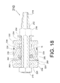
- FIG. 18 is a cross-sectional view taken longitudinally of the test plug of FIG. 16 in which the shaft is shown centered relative to the cone-shaped camming element of the test plug.
- FIG. 19 is a cross-sectional view of the test plug of FIG. 16 positioned within an elbow pipe.
- FIG. 20 is a transverse cross-sectional view of the test plug and elbow pipe of FIG. 19 .
- FIG. 21 is a cross-sectional view of the test plug of FIG. 16 in condition for insertion/removal from the elbow pipe of FIG. 20 .
- FIG. 22 is a cross-sectional view of the test plug and elbow pipe of FIG. 21 with the test plug placed in a condition in which the grippers of the test plug engage the inner diameter surface of the walls of the pipe.
- FIG. 23 is a cross-sectional view of the test plug of FIG. 16 that is positioned within a straight section of pipe and that is in condition for insertion/removal.
- FIG. 24 is a cross-sectional view of the test plug and straight section of pipe of FIG. 21 with the test plug placed in a condition in which the grippers of the test plug engage the inner diameter surface of the walls of the pipe.
- test plugs disclosed herein may be used to temporarily create a fluid-tight seal within and relative to the inner diameter surface of a pipe during a hydro-test, pressure test, or other procedure of a pipe or section thereof.
- the test plugs provide elbow testing capabilities and may be used to test pipe elbows made from various metallic and polymer materials; such as: carbon steel, alloy steel, stainless steel, high alloys, GRE, PVC, FRP, and the like.
- the elbow pipe or pipe section downstream of the plug may be pressurized with a fluid to a pressure sufficient to test for leaks or for any other purpose.
- the test plug must be able to create a seal relative to the inner surface geometry of an elbow pipe such that the seal is able to withstand internal pipe working pressures and remain in a fixed, non-sliding, stationary position within the pipe during testing.
- an installed test plug must resist sliding, movement, blow-out or failure during a testing procedure.
- the test plug must be sufficiently compact that it can be readily inserted into and through the open end of the elbow pipe and must also be able to assume this position upon removal after testing is complete.
- FIGS. 1-6 disclose a first embodiment
- FIGS. 7-15 disclose a second embodiment
- FIGS. 16-24 disclose a third embodiment. These embodiments are disclosed merely by way of example and not by way of limitation.
- Each of the embodiments permits a test plug to successfully provide a strong and reliable grip and leak-tight sealing within pipes having relatively complicated inner diameter surface geometries, such as provided by elbow-shaped or curved sections of pipes.
- at least some of the embodiments are also capable of being applied in straight sections of pipe thereby allowing the same test plug to accommodate different inner surface geometries such as those provided by curved sections of pipes and those provided by straight pipe sections.
- each of the test plugs includes three main components: a seal, a set of grippers, and a shaft.
- the primary function of the seal is to provide a leak-tight barrier during a testing procedure
- the primary function of the grippers is to retain the plug inside of the elbow test pipe
- the primary function of the shaft is to hold all parts of the plug together and to provide a path for providing a fluid, liquid or gas at supply pressure into or from the test area of the pipe.
- One or more of the above referenced components may be aligned eccentric in relation to the others of the above referenced components to enable the test plugs to function properly within a test pipe elbow (i.e., the grippers-to-shaft alignment may be eccentric, the grippers-to-seal alignment may be eccentric, and/or the seal-to-shaft alignment may be eccentric).
- the seal and grippers of the test plug may be eccentrically aligned to each other.
- the seal and/or grippers may be configured to float or self-adjust relative to each other and/or the shaft to better conform to inner pipe elbow geometry.
- the seal and/or grippers may be specifically positioned in the test plug in a fixed location that is eccentric to each other and/or the shaft in order to closely match the inner surface geometry of tested pipe elbow.
- Each of the illustrated shafts may have a section with an outer periphery of a predetermined diameter and may include a jam nut or other fixed end component ( 16 , 116 and 216 , respectively) and a front nut or other front end component ( 18 , 118 and 218 , respectively) that is movable in an axial direction along the shaft for purposes of compressing and/or releasing the assembly of components carried on the shaft between the end components. See FIGS. 1, 7 and 16 .
- threaded nuts are shown as end components on a generally threaded cylindrical part of the shaft, other components, shapes, and means to cause relative movement of the components on the shaft can be utilized.
- the components carried on the shaft between the front and jam nuts may include, for instance, a rear generally annular washer or plate ( 20 , 120 and 220 , respectively), a front generally annular washer or plate ( 22 , 122 and 222 , respectively), a generally annular and resilient seal or sealing element ( 24 , 124 and 224 , respectively), a camming element ( 26 , 126 and 226 , respectively), and a set of circumferentially-spaced grippers ( 28 , 128 and 228 , respectively).
- a rear generally annular washer or plate 20 , 120 and 220 , respectively
- a front generally annular washer or plate 22 , 122 and 222
- a generally annular and resilient seal or sealing element 24 , 124 and 224
- a camming element 26 , 126 and 226
- a set of circumferentially-spaced grippers 28 , 128 and 228 , respectively.
- Other components may include a resilient garter or retaining spring, O-ring, or the like ( 30 , 130 and 230 , respectively) for retaining the set of grippers on the camming element of the test plug and a hardened washer ( 32 , 132 and 232 , respectively) and compression tube or the like ( 34 , 134 and 234 , respectively) which may extend between the front end nut and the front plate to space these components apart permitting the front end nut to be located in a readily addressable position adjacent an open end of a test elbow pipe. For instance, see FIGS. 3, 10 and 19 .
- Each of the rear and front plates ( 20 & 22 , 120 & 122 , and 220 & 222 , respectively) has an opening extending therethrough such that the plates are able to slide lengthwise along the shaft ( 12 , 112 and 212 , respectively).
- the diameter of the openings of the plates may closely match the outer diameter of the section of the shaft on which the plates are carried and slid so that the plates may slide along an axial direction of the shaft with very little or no other motion or play therebetween.
- the front and rear annular plates may be retained in a substantially radial direction of the shaft.
- each of the rear plates ( 20 , 120 and 220 , respectively) has a tapered side outer side edge surface ( 36 , 136 and 236 , respectively) that tapers from a maximum outer diameter to a minimum outer diameter adjacent the jam nut ( 16 , 116 and 216 , respectively).
- the tapered edge ( 36 , 136 and 236 , respectively) permits the rear plate ( 20 , 120 and 220 , respectively) to accommodate concave surfaces of elbow pipes and the like. By way of example, see FIGS. 3, 10 and 19 .
- the front and rear plates ( 20 & 22 , 120 & 122 , and 220 & 222 , respectively) are brought closer together along the shaft causing the set of grippers ( 28 , 128 and 228 , respectively) to slide and advance up a sloping outer surface of the camming element ( 26 , 126 and 226 , respectively) and move radially toward an inner diameter surface of a pipe wall.
- the grippers initially contact the pipe wall and the test plug is then tightened further, the grippers bite into the pipe wall thereby resulting in the test plug assuming a stationary fixed position relative to the pipe. See any of FIGS. 6, 13, 15, 22 and 24 .
- the sealing element which may be made of a resilient material, such as an elastomeric material or the like, expands in a radial direction relative to the shaft and thereby ultimately forms a fluid-tight seal between the inner diameter surface of the pipe wall and the outer peripheral surface of the shaft on which the sealing element is carried.
- the test plug firmly grips the pipe and a fluid-tight seal has been created. Loosening the front nut permits the resilient sealing element to return to its original uncompressed size and shape and releases the grippers from engagement with the pipe wall.
- the camming elements ( 26 , 126 and 226 , respectively) discussed above may each have a generally frustoconical shape (i.e., having the shape of a truncated cone) and a lengthwise extending hollow channel extending therethrough into which the shaft ( 12 , 112 and 212 , respectively) is inserted.
- the outer camming surface of the camming element is in the shape of a truncated cone and therefore provides a sloping surface on which the grippers ( 28 , 128 and 228 , respectively) are carried and may be forced to advance up based on forces exerted by relative movement of the front and rear plates ( 20 & 22 , 120 & 122 , and 220 & 222 , respectively) as discussed above. As the grippers slide upward on the sloped surface, they ultimately are advanced into a gripping position in engagement with the inner diameter surface of the pipe wall.
- Each set of grippers may include four identical, separate, circumferentially-spaced gripper segments that extend about the sloped or cone-shaped outer surface of the camming element. For instance, see FIGS. 4, 11 and 20 . More or less segments may be utilized; for example, the grippers may include six or more segments or only two or three segments.
- Each of the gripper segments may have multiple circumferentially-spaced rows ( 38 , 138 and 238 , respectively) of teeth.
- each segment may have eight uniform rows of teeth as shown in the illustrated embodiments. See FIGS. 1, 7 and 16 . Of course, more or less rows may be provided.
- Each row extends circumferentially relative to the camming element and is longitudinally spaced from the other rows of teeth on the segment.
- Each row may be serrated so that each row on each segment comprises a series of pointed teeth with gaps therebetween. See FIGS. 1, 7 and 16 .
- each row on each gripper segment may provide one elongate continuous tooth.
- each segment may be substantially aligned and may extend to the same outer diameter and each of the gripper segments may be of a uniform shape and size. For example, see the teeth of the grippers shown in FIGS. 15 and 24 which uniformly grip the cylindrical inner walls of a straight section of pipe.
- the hollow channel extending through the camming element 26 of the test plug 10 is offset from a central longitudinal axis C of the truncated cone-shaped camming element 26 .
- FIG. 3 which illustrates the central longitudinal axis C of the camming element 26 being offset by a distance B from a central longitudinal axis A of the open channel of the camming element 26 .
- the open channel of the camming element 26 is offset, this creates a so-called fixed eccentric cone in which, for instance, the outer sloped surface of the camming element 26 is not centered about or equally spaced from the open channel and therefore the shaft 12 which extends therethrough.
- the grippers 28 are supported on the outer sloped surface of the camming element 26 , the grippers-to-shaft alignment is eccentric. Of course, the grippers-to-seal alignment will also be eccentric.
- a first outer surface 40 of the camming element 26 shown in FIG. 2 is spaced further from the shaft 12 than an opposed second outer surface 42 of the camming element 26 .
- the offset B may be of a size that is 3% or greater of the diameter of the hollow channel or may be equal to 5% to 30% of the diameter of the hollow channel.
- any offset may be utilized.
- the camming element 26 fits snuggly about the shaft 12 such that there is little or no gap or play therebetween.
- the camming element 26 may slide along the shaft 12 , but there is otherwise little other motion permitted therebetween.
- the eccentric nature of the camming element 26 carried on the shaft 12 permits the test plug 10 to create better seals and grips on curved surfaces, for instance, provided by elbow pipes and the like. This is accomplished without having to alter or precisely match the outer peripheral shape of the gripper elements to accommodate curved pipe surfaces. All gripper segments of the test plug 10 may be uniform and identical. However, the grippers-to-shaft alignment will be eccentric.
- the test plug 10 may include a dowel or guide pin 44 which prevents relative rotation between the front plate 22 and the camming element 26 but permits movement of the front plate 22 toward and away from the camming element 26 .
- the pin 44 is fixed to the front plate 22
- the camming element includes an aligned cavity 46 permitting entry and withdrawal of the pin 44 which thereby interconnects the front plate 22 and camming element 26 and prevents one from rotating about the shaft 12 without the other.
- the pin and cavity may be reversed such that the pin is carried by the camming element and the cavity is formed in the front plate.
- other mechanisms for preventing relative rotation between these components may be utilized.
- the pin 44 may be located such that it visually identifies the part of the eccentric cone of the camming element 26 that extends a maximum distance from the shaft 12 . For instance, see FIG. 3 and note the location of the pin 44 relative to the direction of offset B.
- the test plug 10 may be inserted into an elbow pipe 50 .
- the elbow pipe 50 will inherently have a curved inner peripheral surface that includes surfaces that are concave and surfaces that are convex.
- the inner surfaces will include a most concave inner wall surface 52 and a most convex inner wall surface 54 as shown in FIGS. 5 and 6 .
- the test plug 10 is located within the elbow pipe 50 such that the pin 44 is located adjacent the most concave inner wall surface 52 of the elbow pipe 50 and opposite the most convex inner wall surface 54 of the elbow pipe 50 . See FIG. 5 .
- the uniform set of grippers 28 advance up the cone-shaped sloped surface of the camming element 26 until they firmly engage the inner wall surfaces of the elbow pipe. See FIG. 6 .
- the test plug is tightly gripped to the curved walls of the elbow pipe.
- Further tightening of the test plug 10 causes the rear plate 20 to advance toward the rear of the camming element 26 to compress the sealing element 24 and cause it to expand into sealing engagement with the inner walls of the elbow pipe 50 and outer wall of the shaft 12 .
- the elbow pipe 50 is ready for testing.
- the first embodiment provides a fixed eccentric alignment between the grippers (which are supported on the outer surface of the cone-shaped camming element) and the shaft. This is provided because the shaft does not extend centrally through the camming element; rather, there is a fixed offset B as discussed above.
- the fixed offset distance may be provided based on the specific pipe size being tested.
- the sealing element when the test plug is tightened, the sealing element will be expanded into sealing engagement with the adjacent pipe walls and will be located downstream from the grippers in the curved pipe. Accordingly, the sealing element in a normal condition and as expanded will be aligned eccentrically relative to the grippers.
- there is an eccentric relationship between the grippers and the shaft and between the grippers and sealing element which enables the plug to properly grip and form a seal in a test pipe elbow.
- the hollow or open channel 160 of the camming element 126 of the test plug 110 extends centrally through the camming element 126 and has a diameter D greater than the outer diameter E of the shaft 112 . See FIG. 11 . Accordingly, the camming element 126 is not only able to slide lengthwise along the shaft 112 , the camming element 126 is also provided with a predetermined amount of play in a direction radial toward and away from the shaft 112 (i.e., the camming element 126 is permitted to “float” relative to the shaft 112 and does not necessarily have to be in direct contact therewith). For example, the shaft 112 may contact one surface of the camming element 126 as shown in FIG.
- the shaft 112 in FIG. 9 is located centrally within the hollow channel 160 of the camming element 126 and is therefore equally spaced from all surfaces of the camming element 126 defining the channel 160 and is not in direct contact with any of the surfaces of the camming element 126 .
- the outer diameter D of the hollow channel 160 may be at least 3% greater than the outer diameter E of the shaft 112 or may be 5% to 30% greater than the outer diameter E. This difference in outer diameters provides a predetermined amount of free movement of the camming element relative to the shaft in a direction perpendicular to a longitudinal axis of the shaft and permits the test plug to automatically accommodate inner surface geometries of elbow pipes.
- the hollow channel 160 and/or the shaft 112 are not required to be cylindrical or have a diameter and may be other shapes, i.e., square, oval, hexagonal, or the like. However, the size of the hollow channel must be greater than that of the shaft to provide an open gap and permit relative floating movement as discussed above.
- the test plug 110 additionally includes a seal washer 162 that extends between the rear of the camming element 126 and the elastomeric sealing element 124 and is able to slide relative to the shaft 212 .
- the seal washer 162 supports the sealing element 124 as it is being compressed to form a seal and prevents any part of the sealing element 124 from extruding into any gap existing between the shaft 112 and camming element 126 within the hollow channel 160 .
- the seal washer 162 is annular and its opening is closely matched to the outer diameter of the shaft 112 with little or no gap therebetween.
- this floating cone embodiment is that, unlike with the eccentric cone disclosed relative to the first embodiment, the test operator is not required to orient or position the test plug 110 in any relation relative to pipe elbow geometry. Thus, both the camming element 126 and the set of grippers 128 of the test plug 110 float relative to the shaft 112 and are free to locate to a best alignment in a radial direction relative to the shaft 112 within an elbow pipe 150 .
- test plug 110 For example, during installation of the test plug 110 , an operator inserts the test plug 10 into an elbow pipe 150 as shown in FIG. 12 and then begins to tighten the test plug 110 by tightening/advancing the front nut 118 relative to the shaft 112 so that all segments of the set of grippers 128 firmly engage the inner wall surfaces of the elbow pipe 150 . See FIG. 13 . While the test plug 110 is being installed, the grippers 128 are automatically placed in best alignment with the inner pipe elbow curvature by the floating action of the camming element 126 relative to the shaft 112 thereby automatically finding the best possible position to uniformly engage and grip the pipe elbow inner surface. Thus, regardless of test plug position and orientation relative to the concave and convex curved surfaces of the elbow pipe 150 , the test plug 110 is able to automatically accommodate the pipe curvature and provide a strong and reliable grip and leak-resistant seal.
- the test plug 110 may also be used in straight sections of pipe.
- FIG. 14 shows the test plug 110 inserted into the open end of a straight pipe section 164
- FIG. 15 shows the test plug 110 as tightened (i.e., in a compressed condition) in which the set of grippers 128 have been advanced into to firm gripping engagement with the inner surfaces of the straight pipe section 164 .
- further tightening of the test plug 110 will cause the sealing element 124 of the test plug 110 to be compressed and expand into sealing engagement with the inner surface of the straight pipe 164 .
- the seal washer 162 prevents any extrusion of the sealing element 124 into the gap between the camming element 126 and shaft 112 .
- the shaft 112 extends concentrically within the open channel 160 of the camming element 126 and cylindrical inner surface walls of the pipe 164 .
- the second embodiment provides self-adjusting alignment between the grippers (which are supported on the outer surface of the cone-shaped camming element) and the shaft. This is provided because the camming element is permitted to float relative to the shaft as discussed above.
- the grippers are aligned in an eccentric relation relative to the shaft.
- the sealing element will also necessarily be in an eccentric relation to the grippers.
- the test plug permits an eccentric relationship to be formed between the grippers and the shaft and between the grippers and sealing element which enables the plug to properly grip and form a seal in a test pipe elbow.
- the test plug 210 of the third embodiment illustrated in FIGS. 16-24 is similar to the test plug 110 discussed above.
- the test plug 210 includes a camming element 226 with a hollow channel 260 having a greater diameter than that of outer diameter of the shaft 212 .
- the camming element 226 “floats” on the shaft 212 and automatically assumes a best position to grip and seal the inner surface geometry of an elbow pipe.
- the test plug 210 includes a seal washer 262 to prevent extrusion of the sealing element 224 in any gap inherently existing between the camming element 226 and shaft 212 within the channel 260 of the camming element 226 .
- test plug 210 also includes an O-ring 266 or like resilient spacing component.
- the O-ring 266 may be seated within a groove or circumferential cavity 268 extending in the wall of the camming element 226 defining the channel 260 .
- the O-ring 266 functions to automatically center the shaft 212 relative to the walls of the camming element 226 defining the channel 260 .
- the O-ring 266 may be made of a resilient material, such as an elastomeric material, and may be resiliently compressible when a pre-determined amount of pressure is applied. For instance, as shown in FIG. 17 , the O-ring 266 is compressed to permit the shaft 212 to extend through the channel 260 such that it is not in a position concentric with the walls forming the channel 260 .
- the test plug 210 includes an O-ring 266 that provides a dampening and cushioning flexible support for the camming element 226 relative to the shaft 212 .
- the test plug 210 provides a camming element that both floats and self-aligns relative to the shaft.
- the significance is that when the test plug 210 is applied within a straight segment of pipe, the shaft 212 automatically assumes a desired concentric position within the open channel 260 of the test plug 210 and inner walls of the pipe. For example, see FIGS. 23 and 24 and the straight pipes in which the shaft 212 is centered by the O-ring 266 and see FIGS. 21 and 22 in which the shaft 212 is offset within the open channel 260 and compresses the O-ring 266 so that the test plug 210 can best accommodate and align with the curved walls of an elbow pipe.
- the third embodiment provides self-adjusting alignment between the grippers (which are supported on the outer surface of the cone-shaped camming element) and the shaft. This is provided because the camming element is permitted to float relative to the shaft as discussed above.
- the grippers automatically self-align in an eccentric relation relative to the shaft.
- the sealing element will also necessarily be in an eccentric relation to the grippers.
- the test plug permits an eccentric relationship to be formed between the grippers and the shaft and between the grippers and sealing element which enables the plug to properly grip and form a seal in a test pipe elbow.
- the test plug 210 performs exceptionally well in various sizes and materials (i.e., metallic, polymer, carbon steel, alloy steel, stainless steel, high alloys, GRE, PVC, FRP, and the like) of pipe elbows (i.e., 90°, 45°, long and short radius) and pipe fittings (tees, wyes, crosses, reduces, etc.).
- the test plug 210 does not require special adjustment during installation, testing or removal, and the set of grippers, sealing element, truncated cone-shaped camming element, and other plug components did not show any unusual wear or damage during tests.
Landscapes
- Engineering & Computer Science (AREA)
- General Engineering & Computer Science (AREA)
- Mechanical Engineering (AREA)
- Physics & Mathematics (AREA)
- General Physics & Mathematics (AREA)
- Examining Or Testing Airtightness (AREA)
- Investigating Strength Of Materials By Application Of Mechanical Stress (AREA)
Priority Applications (5)
| Application Number | Priority Date | Filing Date | Title |
|---|---|---|---|
| US14/827,363 US9823155B2 (en) | 2015-08-17 | 2015-08-17 | Test plug for a pipe elbow |
| CA2910672A CA2910672C (en) | 2015-08-17 | 2015-10-29 | Test plug for a pipe elbow |
| PL16837771T PL3338019T3 (pl) | 2015-08-17 | 2016-08-17 | Korek testowy dla kolanka rurowego |
| EP16837771.1A EP3338019B1 (en) | 2015-08-17 | 2016-08-17 | Test plug for a pipe elbow |
| PCT/US2016/047407 WO2017031233A1 (en) | 2015-08-17 | 2016-08-17 | Test plug for a pipe elbow |
Applications Claiming Priority (1)
| Application Number | Priority Date | Filing Date | Title |
|---|---|---|---|
| US14/827,363 US9823155B2 (en) | 2015-08-17 | 2015-08-17 | Test plug for a pipe elbow |
Publications (2)
| Publication Number | Publication Date |
|---|---|
| US20170052086A1 US20170052086A1 (en) | 2017-02-23 |
| US9823155B2 true US9823155B2 (en) | 2017-11-21 |
Family
ID=58018376
Family Applications (1)
| Application Number | Title | Priority Date | Filing Date |
|---|---|---|---|
| US14/827,363 Active 2035-12-01 US9823155B2 (en) | 2015-08-17 | 2015-08-17 | Test plug for a pipe elbow |
Country Status (5)
| Country | Link |
|---|---|
| US (1) | US9823155B2 (pl) |
| EP (1) | EP3338019B1 (pl) |
| CA (1) | CA2910672C (pl) |
| PL (1) | PL3338019T3 (pl) |
| WO (1) | WO2017031233A1 (pl) |
Cited By (5)
| Publication number | Priority date | Publication date | Assignee | Title |
|---|---|---|---|---|
| US10215322B1 (en) * | 2017-07-14 | 2019-02-26 | Tallgrass Mlp Operations, Llc | Removable oil pipeline branch plug |
| US10774970B2 (en) * | 2018-10-17 | 2020-09-15 | Tdw Delaware, Inc. | Shaft mechanical lock for pipeline isolation tools |
| US11346485B2 (en) | 2018-10-17 | 2022-05-31 | Tdw Delaware, Inc. | Shaft mechanical lock for pipeline isolation tools |
| US11719590B2 (en) | 2018-07-20 | 2023-08-08 | Clearwater Pipe Rentals Inc. | Weld test plugs and methods of use |
| IT202200011867A1 (it) * | 2022-06-06 | 2023-12-06 | Designia S R L | Dispositivo per il collegamento rapido a tenuta ermetica |
Families Citing this family (6)
| Publication number | Priority date | Publication date | Assignee | Title |
|---|---|---|---|---|
| JP6572913B2 (ja) | 2017-01-06 | 2019-09-11 | トヨタ自動車株式会社 | 高圧容器 |
| US11519819B2 (en) * | 2019-11-27 | 2022-12-06 | Caterpillar Global Mining Llc | Seal testing system |
| DE102020101262B4 (de) | 2020-01-21 | 2021-09-23 | Dr. Ing. H.C. F. Porsche Aktiengesellschaft | Kupplungseinrichtung zum Verbinden von hydraulischen Leitungen und Prüfsystem mit einer Kupplungseinrichtung |
| CN114348949B (zh) * | 2022-02-25 | 2023-04-25 | 湘潭大学 | 装配式尾砂浆高效输送测试系统 |
| CN115199852A (zh) * | 2022-06-30 | 2022-10-18 | 亚达管道系统股份有限公司 | 无法兰管口非焊密封装置 |
| US12352378B2 (en) * | 2023-03-08 | 2025-07-08 | Robert Plewa | Expansion plug and system and method employing same |
Citations (14)
| Publication number | Priority date | Publication date | Assignee | Title |
|---|---|---|---|---|
| US4077250A (en) | 1977-02-16 | 1978-03-07 | Wesch William E | Pipe closure apparatus |
| US4381800A (en) * | 1981-08-31 | 1983-05-03 | Thaxton Inc. | Pipe tester plug |
| US4390043A (en) | 1981-06-30 | 1983-06-28 | Shell Oil Company | Internal pipeline plug for deep subsea operations |
| US4817671A (en) | 1988-01-21 | 1989-04-04 | Cherne Industries, Inc. | High pressure mechanical plug device |
| US5676174A (en) | 1995-06-23 | 1997-10-14 | Est Group, Inc. | Outer diameter pipe plug |
| US5797431A (en) | 1995-06-23 | 1998-08-25 | Est Group, Inc. | Inner diameter pipe plug |
| US6467336B1 (en) | 2000-06-27 | 2002-10-22 | Horst Gotowik | Apparatus for testing or isolating a segment of pipe |
| US20030167827A1 (en) | 2002-03-08 | 2003-09-11 | Berneski James P. | Branch pipe/tank nozzle test plug and method of use |
| US20100051130A1 (en) | 2005-03-21 | 2010-03-04 | Harald Syse | Plug With Gripping Means |
| US20100083738A1 (en) | 2007-01-26 | 2010-04-08 | Est Group, Inc. | Test Plug and Method for Monitoring Downstream Conditions |
| US20110278022A1 (en) * | 2009-01-21 | 2011-11-17 | Evald Holstad | Plug for Setting in a Pipe |
| US20120038150A1 (en) * | 2009-04-27 | 2012-02-16 | Swagelok Company | Tapered drive nut for conduit fitting |
| EP2738439A1 (en) | 2012-11-29 | 2014-06-04 | IK-UK Limited | Anchor apparatus |
| US20150369689A1 (en) * | 2014-06-20 | 2015-12-24 | Est Group, Inc. | Gripper for Test and Isolation Plugs |
-
2015
- 2015-08-17 US US14/827,363 patent/US9823155B2/en active Active
- 2015-10-29 CA CA2910672A patent/CA2910672C/en active Active
-
2016
- 2016-08-17 EP EP16837771.1A patent/EP3338019B1/en active Active
- 2016-08-17 PL PL16837771T patent/PL3338019T3/pl unknown
- 2016-08-17 WO PCT/US2016/047407 patent/WO2017031233A1/en not_active Ceased
Patent Citations (15)
| Publication number | Priority date | Publication date | Assignee | Title |
|---|---|---|---|---|
| US4077250A (en) | 1977-02-16 | 1978-03-07 | Wesch William E | Pipe closure apparatus |
| US4390043A (en) | 1981-06-30 | 1983-06-28 | Shell Oil Company | Internal pipeline plug for deep subsea operations |
| US4381800A (en) * | 1981-08-31 | 1983-05-03 | Thaxton Inc. | Pipe tester plug |
| US4817671A (en) | 1988-01-21 | 1989-04-04 | Cherne Industries, Inc. | High pressure mechanical plug device |
| US5676174A (en) | 1995-06-23 | 1997-10-14 | Est Group, Inc. | Outer diameter pipe plug |
| US5797431A (en) | 1995-06-23 | 1998-08-25 | Est Group, Inc. | Inner diameter pipe plug |
| US6467336B1 (en) | 2000-06-27 | 2002-10-22 | Horst Gotowik | Apparatus for testing or isolating a segment of pipe |
| US6601437B2 (en) | 2000-06-27 | 2003-08-05 | United Testing Corp. | Apparatus for testing or isolating a segment of pipe |
| US20030167827A1 (en) | 2002-03-08 | 2003-09-11 | Berneski James P. | Branch pipe/tank nozzle test plug and method of use |
| US20100051130A1 (en) | 2005-03-21 | 2010-03-04 | Harald Syse | Plug With Gripping Means |
| US20100083738A1 (en) | 2007-01-26 | 2010-04-08 | Est Group, Inc. | Test Plug and Method for Monitoring Downstream Conditions |
| US20110278022A1 (en) * | 2009-01-21 | 2011-11-17 | Evald Holstad | Plug for Setting in a Pipe |
| US20120038150A1 (en) * | 2009-04-27 | 2012-02-16 | Swagelok Company | Tapered drive nut for conduit fitting |
| EP2738439A1 (en) | 2012-11-29 | 2014-06-04 | IK-UK Limited | Anchor apparatus |
| US20150369689A1 (en) * | 2014-06-20 | 2015-12-24 | Est Group, Inc. | Gripper for Test and Isolation Plugs |
Non-Patent Citations (1)
| Title |
|---|
| International Search Report and Written Opinion of the ISA issued in International PCT Application No. PCT/US2016/047407 dated Oct. 31, 2016. |
Cited By (5)
| Publication number | Priority date | Publication date | Assignee | Title |
|---|---|---|---|---|
| US10215322B1 (en) * | 2017-07-14 | 2019-02-26 | Tallgrass Mlp Operations, Llc | Removable oil pipeline branch plug |
| US11719590B2 (en) | 2018-07-20 | 2023-08-08 | Clearwater Pipe Rentals Inc. | Weld test plugs and methods of use |
| US10774970B2 (en) * | 2018-10-17 | 2020-09-15 | Tdw Delaware, Inc. | Shaft mechanical lock for pipeline isolation tools |
| US11346485B2 (en) | 2018-10-17 | 2022-05-31 | Tdw Delaware, Inc. | Shaft mechanical lock for pipeline isolation tools |
| IT202200011867A1 (it) * | 2022-06-06 | 2023-12-06 | Designia S R L | Dispositivo per il collegamento rapido a tenuta ermetica |
Also Published As
| Publication number | Publication date |
|---|---|
| CA2910672A1 (en) | 2017-02-17 |
| EP3338019A1 (en) | 2018-06-27 |
| EP3338019B1 (en) | 2019-10-09 |
| WO2017031233A1 (en) | 2017-02-23 |
| CA2910672C (en) | 2018-06-26 |
| PL3338019T3 (pl) | 2020-03-31 |
| EP3338019A4 (en) | 2019-04-03 |
| US20170052086A1 (en) | 2017-02-23 |
Similar Documents
| Publication | Publication Date | Title |
|---|---|---|
| US9823155B2 (en) | Test plug for a pipe elbow | |
| US9664588B2 (en) | Gripper for test and isolation plugs | |
| US11739869B2 (en) | Coupling gasket with multiple sealing surfaces | |
| US8955551B2 (en) | Pipe sealing tool with external and internal clamp | |
| US5797431A (en) | Inner diameter pipe plug | |
| US6601437B2 (en) | Apparatus for testing or isolating a segment of pipe | |
| US9631746B2 (en) | Coupling with tongue and groove | |
| US9194516B2 (en) | Slip-on coupling | |
| US6123363A (en) | Self-centering low profile connection with trapped gasket | |
| AU2012313313B2 (en) | Apparatus and method for sealing a pipe including internal and external gripping means | |
| US3485517A (en) | Pressure fitting for pipes carrying gaseous fluids | |
| US20130187346A1 (en) | Slip-on coupling gasket | |
| US3917324A (en) | Pipe joint | |
| US8096590B2 (en) | Connecting structure for piping | |
| EP0231076A1 (en) | Pipe union assembly | |
| US10563808B2 (en) | Tube leak repair clamp sealing apparatus for use in a nuclear power plant | |
| KR102540073B1 (ko) | 이중지수 이탈방지 구조를 가지는 피복강관 | |
| CN108884954B (zh) | 带有指示器的锁定管道接头装置 | |
| CN114060612B (zh) | 一种新型海底管道水下维修连接装置 | |
| GB2568712A (en) | Sealing apparatus | |
| US20230167934A1 (en) | Plugs for anchoring within equipment and methods of use for pressure testing | |
| RU175275U1 (ru) | Устройство для испытания отводов |
Legal Events
| Date | Code | Title | Description |
|---|---|---|---|
| AS | Assignment |
Owner name: EST GROUP, INC., PENNSYLVANIA Free format text: ASSIGNMENT OF ASSIGNORS INTEREST;ASSIGNORS:SARKISSIAN, KA'REN;KOTLYAR, ALEX;KOBZIAR, DANKO;REEL/FRAME:036339/0019 Effective date: 20150813 |
|
| STCF | Information on status: patent grant |
Free format text: PATENTED CASE |
|
| MAFP | Maintenance fee payment |
Free format text: PAYMENT OF MAINTENANCE FEE, 4TH YEAR, LARGE ENTITY (ORIGINAL EVENT CODE: M1551); ENTITY STATUS OF PATENT OWNER: LARGE ENTITY Year of fee payment: 4 |
|
| MAFP | Maintenance fee payment |
Free format text: PAYMENT OF MAINTENANCE FEE, 8TH YEAR, LARGE ENTITY (ORIGINAL EVENT CODE: M1552); ENTITY STATUS OF PATENT OWNER: LARGE ENTITY Year of fee payment: 8 |