US9816376B2 - In situ evaluation of unconventional natural gas reservoirs - Google Patents
In situ evaluation of unconventional natural gas reservoirs Download PDFInfo
- Publication number
- US9816376B2 US9816376B2 US14/254,079 US201414254079A US9816376B2 US 9816376 B2 US9816376 B2 US 9816376B2 US 201414254079 A US201414254079 A US 201414254079A US 9816376 B2 US9816376 B2 US 9816376B2
- Authority
- US
- United States
- Prior art keywords
- gas
- shale
- wellbore
- methane
- fluid
- Prior art date
- Legal status (The legal status is an assumption and is not a legal conclusion. Google has not performed a legal analysis and makes no representation as to the accuracy of the status listed.)
- Active, expires
Links
Images


Classifications
-
- E—FIXED CONSTRUCTIONS
- E21—EARTH OR ROCK DRILLING; MINING
- E21B—EARTH OR ROCK DRILLING; OBTAINING OIL, GAS, WATER, SOLUBLE OR MELTABLE MATERIALS OR A SLURRY OF MINERALS FROM WELLS
- E21B49/00—Testing the nature of borehole walls; Formation testing; Methods or apparatus for obtaining samples of soil or well fluids, specially adapted to earth drilling or wells
- E21B49/08—Obtaining fluid samples or testing fluids, in boreholes or wells
- E21B49/087—Well testing, e.g. testing for reservoir productivity or formation parameters
- E21B49/088—Well testing, e.g. testing for reservoir productivity or formation parameters combined with sampling
-
- E—FIXED CONSTRUCTIONS
- E21—EARTH OR ROCK DRILLING; MINING
- E21B—EARTH OR ROCK DRILLING; OBTAINING OIL, GAS, WATER, SOLUBLE OR MELTABLE MATERIALS OR A SLURRY OF MINERALS FROM WELLS
- E21B47/00—Survey of boreholes or wells
- E21B47/10—Locating fluid leaks, intrusions or movements
-
- E21B47/102—
-
- E—FIXED CONSTRUCTIONS
- E21—EARTH OR ROCK DRILLING; MINING
- E21B—EARTH OR ROCK DRILLING; OBTAINING OIL, GAS, WATER, SOLUBLE OR MELTABLE MATERIALS OR A SLURRY OF MINERALS FROM WELLS
- E21B47/00—Survey of boreholes or wells
- E21B47/10—Locating fluid leaks, intrusions or movements
- E21B47/113—Locating fluid leaks, intrusions or movements using electrical indications; using light radiations
- E21B47/114—Locating fluid leaks, intrusions or movements using electrical indications; using light radiations using light radiation
-
- E—FIXED CONSTRUCTIONS
- E21—EARTH OR ROCK DRILLING; MINING
- E21B—EARTH OR ROCK DRILLING; OBTAINING OIL, GAS, WATER, SOLUBLE OR MELTABLE MATERIALS OR A SLURRY OF MINERALS FROM WELLS
- E21B49/00—Testing the nature of borehole walls; Formation testing; Methods or apparatus for obtaining samples of soil or well fluids, specially adapted to earth drilling or wells
- E21B49/08—Obtaining fluid samples or testing fluids, in boreholes or wells
- E21B49/087—Well testing, e.g. testing for reservoir productivity or formation parameters
- E21B49/0875—Well testing, e.g. testing for reservoir productivity or formation parameters determining specific fluid parameters
-
- G—PHYSICS
- G01—MEASURING; TESTING
- G01N—INVESTIGATING OR ANALYSING MATERIALS BY DETERMINING THEIR CHEMICAL OR PHYSICAL PROPERTIES
- G01N21/00—Investigating or analysing materials by the use of optical means, i.e. using sub-millimetre waves, infrared, visible or ultraviolet light
- G01N21/62—Systems in which the material investigated is excited whereby it emits light or causes a change in wavelength of the incident light
- G01N21/63—Systems in which the material investigated is excited whereby it emits light or causes a change in wavelength of the incident light optically excited
- G01N21/65—Raman scattering
-
- G—PHYSICS
- G01—MEASURING; TESTING
- G01V—GEOPHYSICS; GRAVITATIONAL MEASUREMENTS; DETECTING MASSES OR OBJECTS; TAGS
- G01V8/00—Prospecting or detecting by optical means
- G01V8/02—Prospecting
Definitions
- This disclosure is directed to a sensor and to a sensing method that identifies the chemical composition of gases, such as solubilized and free gas, and liquids, such as natural gas liquids, water and oil, in unconventional oil and gas shale reservoirs, measures the concentrations of key constituents present in the gases and liquids, determine the partial pressure of each gas species, and equates the various measurements to shale reservoir production factors.
- the disclosed sensor and sensing methods establishes a constant relationship between a gas pressure or composition of gases and liquids in a wellbore and a gas pressure or composition of fluids, comprising gases and liquids, in a far-acting reservoir and then measures these variables in the wellbore using one or more sensors in the wellbore.
- the disclosed sensor and sensing method establishes a dynamic relationship of known quality between a gas pressure or composition of gases and liquids in a wellbore and a gas pressure or composition of fluids, comprising gases and liquids, in a far-acting reservoir and then measures temporal conditions reflecting that dynamic relationship and uses the known quality to calculate a gas equilibrium reservoir pressure.
- the disclosed sensor and sensing method establishes a relationship between the temporal changes in depth of chemical transitions within a fluid column in a wellbore to the origin of each chemical in one or more shale intervals penetrated by the well.
- Methods and apparatus suitable for quickly establishing communication between the wellbore and reservoir are disclosed, as are methods and apparatus for distinguishing between multiple gas and liquid chemical types that may be present in the reservoir, and their origin within a specific reservoir or group of reservoirs.
- the disclosure provides a new reservoir evaluation technology that allows operators to high grade prospective oil and gas shales and target pay zones, allowing operators to avoid non-economic completion costs and water use.
- this disclosure enables more complete evaluation of oil and gas shale resources.
- This evaluation focuses operators on developing completion methods for oil and gas shale targets that warrant investment, reduce overall water usage, and increase the conversion of shale resources into shale reserves.
- the term shale refers to a class of unconventional oil and gas resource rocks that includes shales, clays, tight sands, mudstones, and tight carbonates.
- the invention removes uncertainty regarding estimates of gas-in-place, liquids-in-place, estimated ultimate recovery, and production potential, incenting more rapid capital investment by shale operators and investors, and accelerating hydrocarbon production from these reservoirs.
- This invention enables shale operators to increase exploration success rates, reduce finding costs, reduce completion costs, and reduce environmental impacts without constraining production.
- This invention also relates to a method and system of determining gas content, dewatering time, critical desorption pressure, gas-oil ratio, gas-liquid ratio, ratios of gas and oil to water, estimated ultimate recovery, and/or other reservoir and operational variables, referred to as production factors, for shale wells, wherein the hydrocarbon is at least partially dissolved in water within the reservoir.
- this invention relates to a method and system for measuring a partial pressure of methane and other higher hydrocarbon gases or a predictor substance for a shale gas and liquid reservoir and determining production factors therefrom.
- This invention also relates methods and apparatus that enable active isolation and analysis of shale reservoirs. Testing multiple shale reservoirs situated at various depths in the same well is difficult due to commingling of the fluids from the shale reservoirs that enter the wellbore. As a result, fluids in such multi-zone wellbores may originate from more than one shale reservoir, or only one shale reservoir, depending on relative shale reservoir pressures, and analysis of such fluids cannot readily be attributed to a particular reservoir under static conditions.
- This invention allows ready attribution of fluid properties to the correct shale reservoir by actively isolating part of or a whole shale in a wellbore, flowing fluid from the isolated interval, analyzing such fluid, and thereby analyzing the production factors of interest in that particular shale.
- the invention also relates the apparatus that can be used in this method.
- This apparatus includes isolating the shale intervals by using existing casing, by setting bridge plugs and retrievable bridge plugs, by using pack-off technologies, and/or by using active pumping to favor production of water or oil from a particular shale interval.
- the invention also describes use of a downhole spectroscopic analyzer, a surface spectroscopic analyzer that is coupled to the flowback fluid tubing from the wellbore, and a surface spectroscopic analyzer that is coupled to a downhole sensor analysis chamber using optical fibers with the shale isolation apparatus.
- Shale gas and liquids where gas refers to solubilized and free gas, and liquids refers to natural gas liquids, such as ethane, propane, butane, and also to water and oil, represent the most secure method for the United States to satisfy its current and future hydrocarbon needs. Those needs are driven primarily by U.S. demand for electricity generation (2009 Annual Energy Outlook , Energy Information Administration). A failure to meet those needs with domestic production will result in decreased availability of electricity in the U.S., increased imports of LNG and oil bringing reduced national security, or both.
- Shale intervals are low porosity rocks intersected in many cases by extensive fracture networks. Because shale intervals typically are not saturated with water, many of the fractures contain gas and liquids (typically methane as the predominant hydrocarbon). In fact, 30% or more of the gas in a shale may be compressed into its fracture network.
- Shale intervals typically present an enormous number of possible completion targets. With gross packages ranging from 10 feet to 3000 feet thick, shale intervals present an unusual challenge in selecting completion targets for operators.
- Types of gas and liquids available from shale intervals also vary, with some shale intervals providing nearly pure methane and other shale intervals providing appreciable levels of natural gas liquids, and others yielding oil. As those types of fluids have different market demand, operators need a way to discriminate between areas of differing fluid types in order to strategically focus their production on the most needed resources.
- an existing downhole Raman spectrometer (U.S. Pat. No. 7,821,635 which is incorporated by reference herein in its entirety) is capable of measuring solution gas levels and thereby inferring the partial pressure and hydrocarbon gas and natural gas liquids content of the formation. That technology is extensible to measuring solubilized gas concentrations and gas and liquids composition in shale intervals.
- the potential impact of in-situ Raman spectroscopy technology is immense. To date, shale gas exploration has focused on methane production from intervals oversaturated in gas or significantly under-saturated in water, with success rates similar to the early fairway developments in coalbed methane.
- shale production factors have been determined by a variety of methods.
- One method involves retrieval of a core sample of the shale, transportation of the core sample to a laboratory setting, and quantification of the amount of gas contained within the sample shale via gas desorption. This quantity is then analyzed to determine the shale gas content and compared to an adsorption isotherm of the same, or a similar shale in order to determine the relative amounts of free and adsorbed gas and the critical desorption pressure of the adsorbed phase, in order to estimate the ultimate recovery of gas or liquids from the shale. As mentioned previously however, this process is expensive, very time consuming, and error-prone.
- partial pressure of gas dissolved in a fluid is related to the amount of that gas dissolved in that fluid and that would be in equilibrium with a vapor phase in contact with that fluid.
- partial pressure of gas in fluid is meant to encompass, but not be limited to, related terms such as concentration, effective density, quantity, potential volume, potential pressure, and amount.
- An aspect of certain preferred embodiments of the invention provides that a production factor such as adsorbed gas content, dewatering time, critical desorption pressure, and/or other reservoir and operational variables can be determined via identification of chemical composition of fluids within a gas under-saturated shale and measurement or determination of the partial pressures of methane and other gases, including natural gas liquids.
- a production factor such as adsorbed gas content, dewatering time, critical desorption pressure, and/or other reservoir and operational variables can be determined via identification of chemical composition of fluids within a gas under-saturated shale and measurement or determination of the partial pressures of methane and other gases, including natural gas liquids.
- the invention allows locations of natural gas liquids content to be determined in all shale types by chemical fingerprinting, which involves the ability to detect and identify individual chemical species within the reservoir fluid or wellbore headspace.
- this same finger printing technique is used to determine oil-gas ratio, gas-liquids ratio and other similar fluid ratios to water.
- the critical desorption pressure of adsorbed gases in a gas under-saturated shale reservoir is equal to the partial pressure of those gases in the shale reservoir.
- the associated critical desorption pressures may be determined. If the system is in physical and chemical equilibrium the partial pressures of gases in the gas under-saturated shale reservoir, reservoir fluid and well fluid are all equal. However, in practice this is not always the case as many variables may affect the partial pressures and their interrelation to one another. In such cases other measurements or determinations may be used to correlate the partial pressures.
- production factors applicable to all shale types may be determined utilizing the chemical composition of gases and liquids, movements in transitions between different mixtures of gases and liquids in the wellbore over time, and partial pressure of gases via correlation, modeling, calculation, and other sensor data.
- the measurement of the partial pressure for a particular gas can be accomplished via measurement of the dissolved gas concentration in water extracted from the shale into the wellbore.
- the measurement of the concentration is done at a depth of the shale and as near to the shale as possible so that other variables and effects are lessened.
- This concentration is then correlated to a partial pressure of that gas in the well fluid, and thus shale reservoir.
- the partial pressure of the gas within an gas under-saturated shale reservoir is then used to determine the gas critical desorption pressure along with an adsorbed gas content of the shale reservoir, dewatering time and other reservoir and operational variables.
- the measurement or determination of the partial pressure may also be accomplished in other ways such as by direct measurement of the partial pressure via instrumentation or another variable which correlates to the partial pressure of the gas.
- the concentration of gases dissolved in shale reservoir fluid is measured at a depth in the well at or near the shale of interest. This concentration is then correlated to the partial pressures of those other gases in the fluid. The partial pressures of gases in the fluid are then correlated to the partial pressure of each gas in the reservoir, which equates to their critical desorption pressure in a gas under-saturated shale and is related to the estimated ultimate recovery of each gas.
- a method for determining a production factor or methane gas content of a gas under-saturated shale is achieved by direct measurement of methane concentration of the wellbore fluid. This measurement in combination with a known or determined solubility property for methane in water allows the calculation of the partial pressure of methane in the wellbore fluid.
- the hydrologic and physical connection between these fluids and the shale allows that the measurement partial pressures of solubilized gases in one fluid to be correlated into a measurement of the other two.
- the partial pressure of solubilized gases in the fluids is controlled by the amount of each gas present in the shale. More simply stated; when more methane is present in a particular shale, the partial pressure of methane in the fluids is higher.
- the methane partial pressure in a gas under-saturated shale is the methane critical desorption pressure, which is the methane saturation point of the shale at that pressure.
- Dewatering of the well acts to lower the total fluid pressure to a value at or below the critical desorption pressure, which causes devolution of methane out of the shale as free gas, initially from natural or induced fractures if present.
- the critical desorption pressure can be compared to the rate of decrease of the total reservoir pressure during dewatering, the rate of flow of water from the shale, and other reservoir and operational variables, in order to predict dewatering time and other production factors.
- concentration of methane, other gas, natural gas liquids and oils may be measured by optical spectrometers, membrane-covered semiconductor sensors, mass spectrometers or the like. These concentration measurements can in turn be used to determine gas-oil ratio, gas-liquids ratio and other similar fluid ratios to water.
- concentrations of solubilized gasses which are measured may be directly correlated to a partial pressure for each gas species in the reservoir or any intermediate quantity that is relatable to the amount of each gas in the fluid or parts of the fluid.
- Each shale interval has unique properties which may affect the correlations. By using an intermediate correlation these properties may be used to enhance the accuracy and precision of the partial pressure determination of each gas in the reservoir.
- the production factors which may be derived from determination of the concentrations of solubilized gases are gas partial pressure, percent saturation of adsorbed gas in a gas under-saturated shale, adsorbed gas content, bookable adsorbed reserves, critical desorption pressure, dewatering time, solution gas, stage of production, water salinity, identification of contributing seams and intervals, fluid density, dewatering area and volume, degassing area and volume, gas concentration, reservoir pressure, gas recovery factor, gas-in-place, optimum well spacing, optimum completion designs, including choice of which shale reservoirs or sections within a single shale reservoir to be produced in multi-zone wells and which wells in a pod should be produced first, second, etc., optimum production procedures including choice of which shale intervals and wells to produce first, second, etc., which to abandon or sell, effectiveness of prior completion and production activities, indication of regions and seams of favorable production potential, and other production factors which will be apparent to those skilled in the art.
- Another aspect of the invention is an apparatus and/or system which measures the partial pressure of a hydrocarbon or another substance indicative of the hydrocarbon or measures a precursor variable such as the concentration of the hydrocarbon to allow or produce a determination of the hydrocarbon estimated ultimate recovery of the reservoir.
- the system may include a pressure transducer.
- the pressure transducer can measure the total pressure of the fluid at the measurement point.
- the transducer can also measure a gas pressure down a wellbore when the methane is evolved from the water.
- identification of hydrocarbon species and their concentration or partial pressure is measured by Raman spectroscopy. This may be accomplished by lowering a probe or housing within the well which contains the spectrometer or parts thereof or by guiding a radiation from a radiation source into the well and onto the fluid at or near the shale reservoir from the spectrometer located outside of the well. Characteristic radiation may also be guided from the fluid to the spectrometer located outside the well. Most preferably, the measurement is conducted on the fluid without first sampling the fluid. During sampling, the fluid is necessarily transported and disturbed. By measuring the fluid outside of an instrument package and in-situ the resultant concentration or partial pressure is more accurate.
- This invention also describes a method of combining physical isolation of subsurface geological formations with spectroscopic analysis of fluids in order to quickly and accurately measure key properties of multiple intervals in a single wellbore.
- the method enables, in one embodiment, rapid assessment of each formation as a possible natural gas production target.
- Alone, in situ downhole and surface spectroscopic fluid analysis has been perfected and commercially deployed, but it is challenged in some cases by the movement of fluid downhole between intervals in the wellbore, complicating analysis and interpretation of results when more than one interval is open to a wellbore.
- this invention provides the unexpected benefit of enabling in-situ measurement of fluid properties for multiple zones in a single wellbore without requiring an intervening cemented casing, allowing fast, accurate evaluation of multiple possible production intervals in a single well.
- the method further allows differentiation of fluids from each of these intervals, and thereby differentiation of the properties of various shale intervals penetrated by the well.
- a further unexpected benefit involves the resulting ability to move fluids into and out of each interval independently, thereby providing the ability to obtain far acting reservoir fluids for analysis even in cases where fluid invasion into the interval has occurred.
- a further unexpected benefit involves the resulting ability to combine a variety of complementary fluid physical and geochemical measurements, such as carbon isotope enrichment, fluid conductivity, fluid transmissivity, chemical composition and concentration measurements of solubilized gases, natural gas liquids and oils in a single operational test.
- the method is also suitable for use in a production test mode whereby the fluids are isolated downhole and then delivered to the surface for analysis.
- the present disclosure is comprised of:
- the methods are quantitative, accurate and reproducible.
- the methods includes strategies to remove interfering wellbore and reservoir properties, such as skin damage and low gas transport rates.
- the disclosed methods includes the recognition that the partial pressure of methane and other hydrocarbons in a shale is equivalent to the partial pressure of methane and other hydrocarbons in a shale's pores. As a result, it is e.g., not necessary to directly measure the partial pressure of methane in a shale's pores; that value can be inferred by measurement of the partial pressure of methane in the fracture network.
- the disclosed measurement mode includes establishing a physical or chemical communication with one or more shale intervals and then analyzing fluid, gas or liquids from the matrix or fracture network of a shale, or group of shale intervals and performing trace analysis of solution gases and liquids within that fluid in order to establish the partial pressure of the gases and liquids.
- the partial pressure of methane and other gases in the interval is known, it can be used in a straightforward fashion to calculate the gas and liquids contents and thus gases-in-place of that interval.
- the disclosed measurement mode will be able to identify the intervals with highest concentrations of particular gas species or liquids.
- the disclosed method is designed to discriminate quickly, accurately, and inexpensively between intervals of varying gas-in-place, one apparatus available to use as part of this gas testing method has been adapted from zonal isolation straddle packer systems in some cases, or from simply collected open hole wireline logs over times shorter than crosstalk between intervals can occur.
- FIG. 1 shows a completed shale wellbore
- FIG. 2 shows a diagram of an isotherm calculation based on a gas content
- FIG. 3 shows a diagram of the shale interval fluid system in equilibrium
- FIG. 4 shows a graph of a dewatering measurement
- FIG. 5 shows a process diagram of the measurement system
- FIG. 6 shows a graph of a spectral signature for methane at three different concentrations
- FIG. 7 shows a graph of a calibration between signal (i.e. instrument response) to methane concentration
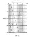
- FIG. 8 shows a graph of a relationship between dissolved methane concentration and partial pressure of methane in a reservoir fluid
- FIG. 9 shows a graphical representation of the relationship between methane partial pressure and shale adsorbed gas content
- FIG. 10 shows a representation of a wellbore with concentrations plotted
- FIG. 11 shows a graph of a measurement when pumping is changed
- FIG. 12 shows a diagram of an isotherm calculation based on a critical pressure
- FIG. 13 shows a flow chart of measurements for a spectrometer
- FIG. 14 shows an averaged shale isotherm
- FIG. 15 shows a diagram of a measuring device
- FIG. 16 shows a diagram of one example of a downhole apparatus with zonal isolation packers that can be used to perform the disclosed method.
- the invention includes a method of reservoir evaluation and an apparatus to perform that method.
- An important aspect of the invention relates to correlation of the reservoir evaluation results with depth so that specific intervals can be targeted for drilling and completion.
- fluids comprising gases or liquids, produced or withdrawn from a target formation
- fluids comprising gases or liquids, produced or withdrawn from a target formation
- Logging speed can be adjusted to collect data faster or slower in order to capture data that describes the movement of those gases and liquids through the wellbore and thereby more accurately attribute those gases and liquids to the particular interval from which they originate.
- Wellbore treatments such as adding acidified water, adding fresh water, adding hydrophilic solvents, or reducing or increasing wellbore pressure, may be undertaken, per normal industry practices.
- Additional data can be collected with other sensors, including but not limited to pressure, conductivity, temperature, video, spectral gamma, flowmeter and pH, concurrently or before or after the spectrometer data collection in order to enhance or enable subsequent data analyses. Any of these data collections can be repeated by multiple logs across the wellbore, or by collection of multiple data points at a stationary depth, in order to measure how the properties measured vary with time, or depth, with the well flowing or shut-in.
- fluids produced or withdrawn from a target formation can be measured by lifting, or allowing flow of, those fluids to the wellhead and into a sample cell in which pressure is controlled and to which a spectrometer is interfaced.
- the spectrometer and other sensors record that measure the concentrations of the fluids, gases or liquids and those concentrations are then correlated to the depth from which the fluids, gases, or liquids were produced.
- Wellbore treatments such as adding acidified water, adding fresh water, adding hydrophilic solvents, or reducing or increasing wellbore pressure, may be undertaken per normal industry practices.
- Additional data can be collected with other sensors, including but not limited to pressure, conductivity, temperature, video, spectral gamma, flowmeter and pH, concurrently or before or after the spectrometer data collection in order to enhance or enable subsequent data analyses. Any of these data collections can be repeated by multiple data points over time, in order to measure how the properties measured vary with time.
- a typical completed shale well includes a borehole which is drilled to at least a depth of a shale reservoir.
- an initial borehole is drilled to or through one or more shale intervals and a casing is set to at least the top of the lowest shale interval.
- Each shale interval of interest is then accessed from the wellbore either by perforating holes from the wellbore into the shale interval, or by open hole completion of the wellbore at the lowest shale interval.
- the wellbore contains water which originates from one or more layers of the geological strata, including some shale intervals, through which the borehole is drilled, or that may be residual from the drilling and completion process. In some instances water may be added to facilitate testing. In some instances the shale intervals of interest are partially or wholly saturated with water. In some cases the shale can be dry or partially dry which means that the shale has no or limited amounts of water. In some cases, shale intervals are stimulated or otherwise treated using techniques such as hydraulic fracturing, acid treatment, recirculation of water, and other known methods.
- fluid from a well may need to be pumped for a very short time (e.g. not at all, if over pressurized with gas) or for a very long time (e.g. up to four years or longer for severely gas under-saturated shale intervals).
- the life of the well during which it produces economical amounts of methane, and the amount of gas that is produced during that time also varies depending on the amount of methane entrained, contained, adsorbed or otherwise present in the shale reservoir.
- a known method of determining the critical pressure which the well must reach in order to produce methane by desorption is by determining an isotherm of the shale or shale gas content curve which represents the amount of adsorbed methane the shale may contain depending upon the pressure.
- a sample of the shale from the interval itself is subjected to reduced pressure over time to measure the amount of methane which it contained.
- To this measurement is added a “lost gas” estimation to account for gas that issued from the shale sample during retrieval.
- the total amount of methane is then plotted on the isotherm chart and a correlation is made to the ideal curve. Where the saturation gas curve and measured gas content intersect is the critical pressure which must be reached in order for the reservoir to release the adsorbed methane. Other factors may be deduced from this plot or map.
- the methane present in the shale is interrelated to the methane of the reservoir fluid, which in turn is interrelated to the methane present in the well fluid.
- the pressure is reduced on the well fluid, the pressure is in turn reduced on reservoir fluid and in turn reduced on the shale interval.
- the shale interval, reservoir fluid and well fluid are initially at equilibrium. When one of these is changed the others are affected. The changes are not instantaneous. For example, a reduction of the pressure in the well fluid propagates from the well into the shale reservoir first affecting the pressure of the reservoir fluid and then the pressure of the shale reservoir.
- the propagation of the change may depend on many factors including the fluids, the shale intervals, permeability, porosity, density and fracturing of the shale. However, given time the change propagates as the system moves toward equilibrium by affecting the shale reservoir, reservoir fluid and well fluid properties.
- methane gas begins to desorb and flow from the shale itself. This process is what occurs when the well is for example dewatered using a downhole pump. The water level or head is reduced so that the pressure is reduced and gas is produced.
- the wellbore and reservoir fluids have an effect on each other as well as on the shale interval.
- a concentration of a substance in the fluid, a pressure or other variable can locally change for the well fluid. This in turn affects the reservoir fluid and the shale interval.
- the change propagates into the interval fluid and shale, and the system responds by seeking to reestablish equilibrium.
- a flux or gradient develops between the well fluid and the reservoir fluid and shale.
- the concentration, pressure or the like may be calculated for a given point within the reservoir fluid or shale interval. This calculation may assist in determining the characteristics of the reservoir based upon a measurement of the well fluid when the well fluid is out of equilibrium with the reservoir. Thus, a measurement of the gas content or critical pressure of the methane for the shale interval may be calculated during dewatering, i.e. under non-equilibrium conditions.
- a computer model may be used to determine the flux or difference in concentration or pressure as well as measurements of other variables such as the porosity, flow characteristics or other flux variables present in the well and reservoir.
- the partial pressure of methane is directly affected by the amount of methane contained or present in the shale interval and by the ease with which that methane can adsorb, absorb or otherwise be contained within the shale.
- the more methane that is present in the shale interval then the higher the partial pressure of methane in the fluids.
- the partial pressure of methane in the reservoir fluid is directly related to the amount of methane in the shale interval.
- any further reduction in pressure causes the methane to transport off of or out of the shale interval as gas.
- An example of this is when dewatering causes the overall reservoir pressure to be lowered below the critical desorption pressure in a shale gas well and gas production to commence.
- the methane critical desorption pressure in a gas under-saturated shale interval can be determined.
- the partial pressure of methane is dependent on the amount of methane in the shale interval the partial pressure of methane does not significantly change for a system at equilibrium.
- the partial pressure of methane in the shale reservoir fluid remains constant as long as the fluid pressure is above the critical desorption pressure. This constancy of the methane partial pressure in the shale reservoir fluid can be observed, for example during a dewatering process when the hydrostatic pressure on the fluid is being continuously reduced.
- the partial pressure of methane of the reservoir fluid is the critical desorption pressure for the shale interval.
- the critical desorption pressure of a gas under-saturated shale can be determined. This, in turn, given an isotherm of the shale, can establish the adsorbed gas content of the shale interval, and can also aid estimation of the methane reserves within the shale reservoir.
- the total reservoir pressure over time during dewatering of a gas under-saturated shale may be plotted based on a linear or fitted curve and compared against the methane partial pressure. The dewatering time may then be determined.
- Direct measurement of the partial pressure of the methane in the fluid or fluids can be made by a METS sensor or a total gas pressure sensor with an appropriate filter.
- a measurement of a substance which is indicative of the methane partial pressure may also be used such as carbon dioxide or nitrogen or other substances which chemically or physically interact with the methane in the reservoir.
- Another way of determining the partial pressure is by direct physical observation of the fluid in the well.
- fluids near the bottom of the well can contain higher concentrations of methane and fluids near the top of the well can contain lower concentrations of methane.
- the saturation limit of methane in water increases with increasing pressure, which increases with increasing water head or depth.
- methane For a wellbore fluid that contains dissolved methane, that methane will remain dissolved at depths where its concentration is lower than the saturation concentration and will cavitate as gas bubbles, to some extent, at depths where its concentration is higher than the saturation concentration.
- the depth at which cavitation commences is that depth at which the water head pressure is equal to the methane partial pressure. At depths above this point, the methane partial pressure exceeds the water head pressure and cavitation occurs. At depths below this point, the methane partial pressure is less than the water head pressure and cavitation does not occur.
- a video camera, acoustic device, bubble counter, thermocouple or other transducer of the like which is sensitive to the presence or evolution of bubbles in a fluid may be used to observe the depth at which the water head pressure is equal to the methane partial pressure. The pressure at this depth is then equal to the partial pressure of methane within the system or well fluid at the shale interval.
- This method of determining the partial pressure has several drawbacks in that other gases could be cavitating which would affect the observation and other dynamics of the well could offset the determination.
- Another way of determining the partial pressure of methane within the system or well fluid is by capping the well and allowing the system to reach equilibrium.
- the capped well produces gaseous methane which fills the headspace of the well along with other gases.
- These other gases can be water vapor, carbon dioxide or other reservoir gases.
- the partial pressure of the methane is included. If the other reservoir gases are subtracted out, by measurement or by assumption, or assumed to be near zero, then the resultant pressure is the partial pressure of the methane.
- this partial pressure of methane would be the partial pressure of methane in the system the critical desorption pressure would be known.
- This method is similar to a sipper tube or canister which draws in well fluid or reservoir fluid and is taken out of the well for analysis of the partial pressure of the methane in a similar manner.
- the sample is allowed to come to equilibrium, or a relationship between the sample state and equilibrium is determined or estimated.
- the pressure of the vessel is measured, and the fraction of that pressure which is due to the gas or gases of interest is measured or assumed. From those quantities, the partial pressure of the gas or gases of interest is calculated
- Another example uses a sample collected and handled as above, in which localized, microscopic or macroscopic changes in vessel pressure are induced in order to induce gas evolution from the fluid.
- the system is allowed to come to equilibrium, or a relationship between the system state and equilibrium is determined.
- the pressure of the vessel is measured, and the fraction of that pressure which is due to the gas or gases of interest is measured or assumed. From those quantities, the partial pressure of the gas or gases of interest is calculated.
- This method has several drawbacks in that other gases including water vapor interfere with the measurement and creates uncertainty.
- the assumptions associated herewith as well as the necessity of having equilibrium in the well and fluid collection make this method undesirable.
- Another example of determining the partial pressure directly is to submerge a vessel with a known volume, containing known or assumed fluids or gases and equipped with a gas-permeable membrane, into reservoir fluid or a wellbore, and the dissolved gases in the water are allowed to equilibrate with fluid(s) and/or gase(s) in the headspace, then the gas partial pressure in the headspace is measured with a pressure transducer or other transducer sensitive to the pressure, activity, fugacity or concentration of the gas or gases of interest. This can be combined with a sensor that identifies the fraction of the headspace volume (and thus partial pressure) that is due to the gas or gases of interest.
- the fluid within the well may also be physically altered.
- this method to determine the partial pressure one may stimulate cavitation in a reservoir fluid using a source of energy such as a sonic gun or the like and correlate the extent of cavitation as a function of energy to the partial pressure of the gas or gases of interest.
- the reservoir fluid may be heated using a variety of heating devices, including immersion heaters, microwave generators, or injection of steam of other hot fluids into a device, pipe or other container in contact with the fluid. The resulting increase in temperature will reduce the solubility of the methane in the fluid.
- the correlation of cavitation to heat input and/or temperature rise can be correlated to the partial pressure.
- Another example of a method of directly determining the partial pressure is to retrieve a volume of shale from the shale interval and seal the sample in a container at the reservoir conditions. This sample can then be allowed to off-gas methane in a sealed volume. When the sample comes to equilibrium the pressure in the sealed volume is the partial pressure of methane in the shale interval. This method is problematic in that retrieval of a sample without affecting the methane partial pressure of that sample is difficult.
- Another determination of the partial pressure of methane in the fluid or fluids may be made by measuring the concentration of methane or other substance indicative thereof.
- the following example is directed toward a method involving measuring a concentration of the methane in order to determine the partial pressure of the reservoir fluid and in turn to determine production factors in a gas under-saturated shale, but should not be considered as limiting the method or apparatus.
- a method of certain preferred embodiments of the invention involves measuring a concentration of methane dissolved in a shale reservoir fluid, correlating that concentration to a partial pressure of methane in the fluid, correlating that partial pressure to the partial pressure of methane in the reservoir, and correlating that partial pressure of methane in the reservoir to an adsorbed gas content in the shale as well as determining other production factors.
- FIG. 6 shows the Raman spectral signature of methane dissolved in water for three different samples having different methane concentrations.
- FIG. 7 shows such a calibration for Raman signal responses to methane dissolved in water.
- Dissolved methane concentration can then be calibrated to partial pressure of the methane in the reservoir fluid.
- this relationship is typically a simple linear relationship.
- this relationship may be complex.
- This relationship can be established for any fluid or condition by preparing samples of reservoir fluids under reservoir conditions, by impinging a partial pressure of methane onto the sample until the system is at equilibrium and by then measuring the concentration of methane. This process can be repeated for more than one partial pressure of methane until a relationship between dissolved methane concentration and partial pressure is established.
- the partial pressures impinged would be of magnitudes that include the partial pressure magnitude expected in the reservoir.
- FIG. 8 For example, a relationship between dissolved methane concentration and partial pressure of methane typical of some shale reservoir fluids is shown in FIG. 8 .
- the methane partial pressure in a reservoir fluid can thus be determined by measurement of the dissolved methane concentration in that fluid.
- the methane partial pressure in a reservoir fluid can then be used to determine the methane partial pressure in an overall shale interval.
- the methane partial pressure in a reservoir fluid or well fluid is equal to the methane partial pressure in the overall reservoir.
- the methane partial pressure in a reservoir can then be used to determine the adsorbed gas content of a gas under-saturated shale reservoir.
- FIG. 9 shows such a relationship typical of shale.
- measurement of the concentration of methane dissolved in a shale reservoir fluid can be used to analyze quantitatively the adsorbed gas content of the shale interval.
- Another way of performing certain preferred embodiments of the invention are to measure the concentration of methane in the well at varying depths. This results in a plot of the concentration of methane versus the depth as shown in FIG. 10 .
- the concentration of methane is shown plotted with Henry's law (solid line), or other models of the saturation limit of methane in water, against depth. As depth is increased, the measured concentration is saturated to a certain point A. At this point the concentration of methane in the water deviates from the saturation curve. This deviation point is indicative of the partial pressure of methane in the well fluid.
- the partial pressure of the methane in the well fluid is the head or pressure of the water at the deviation point.
- Measurement of the dissolved methane concentration in a reservoir fluid can occur using a number of different methods and apparatus.
- Measurements can be made downhole in a well that is drilled into a shale interval, and manipulated to contain the reservoir fluid. Such measurements can be made using an optical spectrometer, such as a Raman spectrometer. Such measurements can be made using a membrane-coated semiconductor sensor. Such measurements can be made using a mass spectrometer. Such measurements can be made using a sensor such as an optical spectrometer in tandem with a sample collector such as a formation tester or with a fluid control system such as a coiled tubing pump system. Such measurements can be made using a nuclear magnetic resonance spectrometer or a radio frequency, acoustic frequency, or microwave frequency spectrometer. Such measurements can be made using any transducer or sensor that provides a signal in response to methane concentration, including those transducers and sensors that may be less than quantitative in signal response.
- Measurements can be made at the wellhead in a well that is drilled into a shale interval, and manipulated to contain the reservoir fluid. Such measurements can be made using standard laboratory analysis, e.g. via gas chromatography, on samples collected with various sampling apparatuses, including vessels that allow fluids of interest to flow into them and then seal, on samples that are collected at the wellhead using a pressure-regulated pumping system, and on other samples collected using methods obvious to those skilled in the art.
- fluids in a wellbore are not representative of a reservoir.
- a wellbore drilled into more than one shale interval may contain commingled fluids that are representative of those intervals, in some ratio.
- concentration measurements can likewise reflect the properties of those intervals, in some ratio.
- Wellbores and wellbore fluids can be manipulated in order to ensure that the wellbore fluid properties, most specifically the methane concentration but also the temperature, pressure, ionic strength, and/or other physicochemical properties, reflect the reservoir properties of interest.
- wells can be completed in only one shale interval so that other shale intervals or geologic intervals cannot contribute fluids to the wellbore.
- the wellbore fluids in a well drilled into a shale interval can be allowed to equilibrate with the shale interval until the wellbore fluids reflect the properties of the shale interval.
- the wellbore fluids can be extracted from the wellbore in order to induce fluid flow from the interval into the wellbore until the wellbore fluids reflect the properties of the interval of interest.
- multiple shale intervals in a well can be isolated using bridge plugs, packers, or other such apparatuses. The wellbore fluids in the isolated regions can then be allowed to equilibrate with the associated shale intervals, or one or more isolated regions can be evacuated with pumps or other mechanisms in order to induce fluid flow from the shale interval into the isolated regions until the fluids in the isolated regions reflect the shale interval properties of interest.
- the aforementioned formation tester, or other straddle packer assembly with a tester valve can be used to extract fluid from the sidewall of a well until the fluid extracted represents the desired reservoir property.
- this could involve using the straddle packer assembly to extract fluid from one shale interval, in a wellbore that contains fluids commingled from more than one shale interval, until the fluid contained in the pipe above the straddle packer assembly reflects only the properties of that one shale interval. Then, the concentration measurement could be performed on that sample either at the surface or in the well.
- Fluid manipulations can be used to draw fluids from various places in a reservoir, and thus provide the opportunity to analyze the properties of those places without drilling a well to them.
- key reservoir variables of a shale interval near a wellbore can be analyzed by measuring the methane concentration and other properties of a wellbore fluid.
- the wellbore fluid can then be removed from the wellbore so that additional fluids flow from the shale interval into the wellbore.
- the wellbore fluids can again be analyzed with the expectation that the fluids reflect the properties of the interval farther from the wellbore.
- a portion of the sidewall can be covered so that fluid is removed from the surrounding shale interval in only one cardinal direction.
- the rate of fluid removal, and the properties of the fluid and substances that it contains can indicate reservoir properties of interest such as fracturing orientation, and dewatering and production volume aspect ratio.
- the Henry's law saturation curve during pumping is represented (solid line) as well as the saturation curve for when the pump is turned off (gray line).
- concentrations of methane solid circles
- concentrations of methane solid circles
- concentrations of methane near the pump off curve indicate that the well is being produced effectively and that dewatering time has been long and/or permeability is high as well as a very small cone of depression.
- Concentrations close to the saturation curve for when the pump is on indicate that the cone of depression may be large and dewatering time has been short and/or permeability is low.
- one shale interval can be extremely large. Some shale intervals may be 100 feet or larger in thickness. By measuring concentrations and chemical composition at different places along the shale the resultant partial pressures may be used to identify and determine production factors that may not be representative of one measurement. A cone of depression may actually be able to be identified if the cone of depression has vertical stratification along the shale. Other variables for the seam may also be determined via measuring along the entire width, such as locations of natural gas liquids production.
- FIG. 12 represents a plot of gas content and total reservoir pressure.
- the line indicates where in that space the shale adsorbed gas content is saturated. Measurement of methane concentration, and thus adsorbed gas content, for a shale interval at a certain reservoir pressure allows mapping of that particular reservoir onto this space. Intervals that adhere to the saturation line are saturated with gas. Intervals that do not adhere to the saturation line contain are under saturated with gas.
- Point A indicates an example interval that is under saturated with gas.
- the overall pressure must be reduced until equal to the methane partial pressure, termed the critical desorption pressure.
- the saturation line is the same or nearly the same for more than one area of shale or more than one shale interval, allowing direct comparisons to be made. In other cases, the saturation line must be measured, e.g. by adsorption isotherm analysis of cuttings, in order to allow comparison.
- the partial pressure of methane in the fluid surrounding the shale interval and the isotherm of the shale are provided.
- the isotherm is a correlation, at a given temperature, between the partial pressure of methane and the adsorbed storage capacity of the shale interval, i.e. saturated methane gas content.
- the isotherm should be known or estimated externally to the Raman measurement.
- the goal in making the Raman measurement is to determine the partial pressure of methane in the fluid surrounding the shale interval.
- the instrument is calibrated. This is done by one of two methods. Both involve preparing samples of methane in equilibrium with water at various pressures. Raman spectra of the samples are taken. The pressures of the samples should correlate with the range of methane partial pressures expected in the unknown samples.
- the concentration of methane in each sample's fluid can be calculated by Henry's law, using an appropriate Henry's law constant for the given conditions, i.e. temperature, salinity and methane partial pressure, or by some other method that indicates the solubility of methane in water.
- This methane in fluid concentration can then be correlated with the intensity of the methane peak in the Raman spectra of the sample. This method is robust and has several advantages.
- the partial pressure of methane can also be directly correlated with the intensity of the methane peak in the Raman spectra.
- either methane concentration or partial pressure can be calculated by measuring the Raman spectrum of an unknown sample.
- Correlating directly to partial pressure while simpler, introduces a larger possibility for error, as the unknown fluid may not have the same relationship between dissolved methane and partial pressure, i.e. Henry's law constant (or other solubility relationship).
- correlating to concentration and then to partial pressure provides the advantage that the relationship between concentration and Raman signal will not be affected by differences in the fluid quality, without it being obvious in the Raman spectra, example: an unknown peak in the same spectral range as the methane.
- Another example of the steps to determine the partial pressure based upon an optical measurement of the methane concentration to reach partial pressure is as follows. First, construct a calibration of Raman or other spectrometer counts that relates those counts to methane concentration dissolved in water (preferably, an ideal water such as deionized water). This requires that one first apply a methane partial pressure at a room temperature and allow the system to come to equilibrium; preferably this is done for a pressure range that exceeds the range of interest in the well. Then, one measures the Raman signal from the methane in the ideal water sample and calculates the methane concentration dissolved in that sample. Then, one can correlate this concentration with the methane partial pressure that was applied, using a Henry's law constant for water at room temperature. This gives a calibration between Raman signal, concentration in the water and partial pressure of methane above the water at room temperature.
- water preferably, an ideal water such as deionized water
- a concentration of the methane in the well water is calculated, via computer or model.
- a production value can be obtained.
- the use of an ideal gas content curve or shale isotherm is needed in order to determine the shale adsorbed gas content.
- a cutting or core sample of the shale may be used to determine the actual shale isotherm.
- an isotherm from a similar shale may be used as well as an isotherm which is representative of a shale, shale type, shale formation or shale basin/region.
- a library of shales may be compiled in order to allow automated determinations based on the shale. This may result in a range of values dependent on the isotherms used.
- Another example of automating the determination of the shale gas content is by using a model based upon equations.
- Equation 1 Using Equation 1 above with these values, one can enter any value of P m and obtain the corresponding value of G for shales for which the typical isotherm in FIG. 15 is suitable. To predict the isotherm a bit more closely reiterations and other modifications can be done.
- Methods of directly determining or measuring amount of gas in a shale interval or region of a shale interval can include, but are not limited to, spectroscopies in which energy travels into the shale interval and interacts with methane or substances indicative of the amount of methane. Examples include acoustic spectroscopy, microwave spectroscopy, ultrasonic spectroscopy, Raman spectroscopy, reflectometry, and the like. In an example case, microwave radiation of the appropriate wavelength is impinged on a shale interval, travels through the shale to an extent that allows sufficient interaction with methane, and a method of detection based on that interaction that provides the amount of methane entrained in the shale interval is used. That amount of methane is related to the adsorbed gas content of the shale.
- the apparatus to carry out certain preferred embodiments of the invention includes as shown in FIG. 15 a partial pressure sensor or measuring device and a comparator for comparing the methane partial pressure to the isotherm.
- the partial pressure measuring device includes a concentration measuring device and a calibration system to calibrate the concentration of dissolved methane to the partial pressure.
- the apparatus may include other sensors such as a temperature sensor, salinity sensor and/or a pressure sensor. The measurements for each of these may be used by the calibration system in order to determine the methane partial pressure.
- the system used to measure the concentration may also contain other measuring devices for salinity or electrical conductivity as well as temperature and pressure.
- the system will measure the temperature and the electrical conductivity of the reservoir fluid with the concentration. This will allow a more accurate determination of the methane partial pressure in the reservoir fluid.
- salinity can be determined by analyzing the distortion seen in the water O—H stretch Raman peak present in the acquired spectra.
- the O—H Raman peak is a composite of both symmetric and asymmetric stretch modes. It is well known that the height ratio of the individual symmetric and asymmetric modes varies with increasing salinity.
- a system which includes a concentration sensor for use downhole may be preferable due to its size and speed.
- An optical instrument for use down a well is comprised of a radiation source which is directed through a series of optical components to a sampling interface where the radiation interacts with a sample that is outside of the instrument and across this interface. The returning radiation is then directed through a series of optical components to a spectrometer.
- a controlling device inputs operating parameters for the spectrometer and packages spectral data for delivery to an uphole computer.
- the entire instrument is packaged in a steel housing, with additional sensors for pressure, temperature, and conductivity incorporated into the housing endcap.
- the instrument is attached to a cable head and lowered into a wellbore by a wireline winch.
- the uphole computer and software allows a user to set operating parameters for the instrument and graphically display data delivered from the controlling device.
- a calibration file is created by correlating response and spectra of dissolved methane to known concentrations of dissolved methane.
- the calibration file is used to predict methane concentration from the spectra delivered uphole by the instrument.
- Additional calibrations are created at various temperatures and salinities to develop a library of Henry's law constants to be used in order to calculate methane partial pressure.
- the values of temperature and conductivity measured downhole are used to choose an appropriate Henry's law constant from the library and calculate a methane equilibrium partial pressure for the interval from the concentration measured by the instrument.
- This methane equilibrium partial pressure is the critical desorption pressure. As the total pressure (hydrostatic pressure) falls below the critical desorption pressure, the well begins stable gas production.
- gas content is calculated using the value for critical desorption pressure in conjunction with an isotherm that is representative of the shale's ability to sorb methane.
- An isotherm is a plot of total methane pressure with respect to a shale interval's holding capacity for methane, in standard cubic feet of gas per ton of shale. A technique as described above may be used to determine an isotherm.
- the rate at which the hydrostatic pressure head (water level) can be lowered depends on the discharge rate of the pump, the well completion method, relative permeability of the interval and interval recharge rate. By noting the static water level before water discharge begins, one can monitor the hydrostatic pressure drop with a pressure transducer attached just above the pump and determine the rate at which the hydrostatic pressure drops with respect to total water discharge. This rate can be used to predict the time need to reach the critical desorption pressure of the well or the dewatering time as described above.
- the depletion area of water from the interval, or cone of depression can be modeled using hydrological assumptions and water discharge rates to determine the lateral extent of interval at or below the critical desorption pressure and actively contributing to stable gas production.
- a number of methods familiar to those skilled in the art can be utilized in order to increase further the accurate correlation of the results with depth of interval by isolating a particular interval physically in order to enable interacting with a particular interval separately from others that may be intersected by the wellbore.
- Such interactions may include instigating changes in fluid flow, pressure, or other physical or chemical properties from the wellbore to the interval, or allowing or encouraging changes in similar properties from the interval to the wellbore.
- the results of those interactions can be that fluid samples or physical properties such as pressure transients that represent the reservoir properties of the interval can be collected or analyzed in situ in order to calculate those reservoir properties.
- the methods of isolation include but are not limited to: testing on penetration, before other potentially interfering intervals are intersected by the wellbore; setting retrievable or non-retrievable bridge plus, in order to isolate an interval targeted for testing from other intervals occurring at greater depths; using swellable packers either in a straddle mode or in a single packer mode to isolate the target interval from other intervals in the wellbore; and exploiting flow rates of fluids with or without active pumping in order to attribute the properties of flow streams analyzed at different times to intervals at different depths.
- One apparatus allows ready attribution of fluid properties to the correct formation by actively isolating intervals in a wellbore, drawing out fluid from each formation, analyzing such sample, and thereby analyzing the production factors of interest in that formation.
- This apparatus includes isolating the intervals by using pack-off technologies, and/or by using active pumping to favor production of fluids from a particular interval, in conjunction with or instead of wellbore treatments.
- Sealing mechanisms for isolating hydrocarbon bearing zones are readily available throughout the industry, commonly referred to as straddle packers, and the like.
- a variety of packer types are available which can be used to enable the current invention, including pressure set inflatable packers.
- These mechanisms are deployed with a variety of complementary tools such as valves, sensors, samplers, pumps, etc.
- the valves can be manipulated by using pressure applied down the inside or outside of the deployment work string, rotation of the work string, changes in compression applied to the work string, or vertical movement of the work string, with all types being compatible for use with the present invention.
- FIG. 16 illustrates one embodiment to effect the disclosed invention based on use of an inflate-style test string with no external umbilicals or power cables, that is deployed on a tubing work string, and either a downhole spectroscopic analyzer, a surface spectroscopic analyzer or a surface spectroscopic analyzer that is coupled to a downhole sensor analysis chamber using optical fibers.
- the test string is lowered into a well on a work string. It is positioned in front of a shale interval, and the packers are used to isolate that interval from the remainder of the wellbore, and especially from other intervals in the well.
- a valve situated at the bottom of the work string is then opened to allow pressure communication with the target interval.
- a variety of methods including but not limited to blow-downs, whereby the fluid level in the work string is evacuated up the well-tubing annulus by pressure acting on the surface of the fluid, swabbing, or by circulating fresh water, can be employed to induce flow of fluids from the shale interval into the work string.
- Properties of the produced fluid at the bottom of the work string as a function of depth and time can be determined using either a down hole spectroscopic analyzer deployed on a guide wire with electrical conductors, or a guide wire with a set of optical fibers connected to a spectroscopic analyzer situated at the surface, or by moving the produced fluid, gas and/or liquids to the surface for analysis with a spectrometer or other sensor system.
- Blow-down and/or pumping and subsequent spectroscopic analysis cycle can be repeated to validate results or until the fluid properties at the bottom of the work string reach a steady state or other condition, where this condition indicates that the fluid properties including composition, concentration and partial pressure can be related to the authentic reservoir in the interval.
- measurement of the fluid properties allows determination of selected properties of the interval, such as its ethane content and the originating depths within the shale of ethane production, as described above.
- the packers may be released which allows the test string to be moved to a second interval in the wellbore.
- the measurement and analysis described above may be repeated, allowing the determination of the properties of the second interval. This process may be repeated until substantially all of the hydrocarbon-bearing intervals in a given well have been analyzed. This method allows the analysis of the gas and liquids content for each of the seams in a multi-seam well.
- FIG. 16 further illustrates a belly spring 101 is run on the bottom of the tool string to provide drag and prevent rotation of the straddle packer assemblies 103 , 109 during the inflation & setting process.
- a receiver sub 102 sits above the belly spring and below the bottom straddle packer 103 . This sub allows pressure in the sump 126 to equalize with annulus pressure 127 above the top straddle packer 109 via an internal conduit 123 connected to bypass sub 110 .
- the Straddle Packer Assemblies 103 and 109 are comprised of a chassis and an interchangeable, inflatable, rubber element. These elements can vary in length.
- the Top Straddle Packer 103 contains an inner mandrel to accommodate internal conduit 123 and conduit 124 used to set and maintain pressure in the two Straddle Packers 103 & 109 , while the other Straddle Packer 109 also accommodates conduit 125 , which provides a path for fluids between the test interval 128 and work string 122 .
- Spacing pipe 104 and/or drill collars 105 are used to span the height of test interval 128 .
- Bypass pipe 106 is run inside the spacing pipe 104 & drill collars 105 to accommodate conduits 123 and 124 .
- the outside recorder carrier 107 carries two electronic memory pressure gauges (EMPG or gauges) to record formation pressure and straddle packer inflation pressure.
- EMPG electronic memory pressure gauges
- the flow sub 108 allows fluid exchange between the test interval 128 and conduit 125 . It also accommodates the other two conduits.
- Screen filter 111 filters out all coarse particles in the wellbore fluid drawn into the inflate pump 112 . It consists of an outer perforated case, a fine inner screen and two inner mandrels to accommodate all three conduits 123 - 125 . Both straddle packers are inflated by repeated clockwise rotation, and deflated by compression and discrete clockwise rotation, of the inflate pump 112 , which incorporates an interchangeable pressure relief valve dictating the maximum straddle packer inflation pressure.
- the inside recorder carrier (IRC) 113 includes two gauges to record formation pressure. If pressure inside the conduit 125 increases above hydrostatic due to fluid squeeze generated during inflation of the packers it is released into the annulus 127 through the squeeze relief sub 114 . If blow-down operations are used to withdraw fluid from the shale reservoir into the work string 122 the squeeze relief sub 14 is not used.
- the safety joint 115 features a course thread and a friction ring between the top and bottom sub. Should the test string become stuck it is possible to back-off the upper assemblies at the safety joint by rotating anti-clockwise. The back-off torque required is 60% of the make-up torque.
- the hydraulic jar 116 combines a hydraulic time delay and mechanical trigger mechanism that delivers a controlled jarring action to help free stuck bottom hole assemblies.
- the hydraulic time delay provides a temporary resistance that allows the drill pipe to be stretched.
- the trigger mechanism causes the tubing stretch to be released, with the resulting sudden contraction delivering a substantial impact force.
- Sample chamber 117 is mechanically connected to the hydraulic shut-in tool (HSIT) or Valve Assembly 118 , allowing it to capture a fluid sample when the Valve Assembly closes.
- the Valve Assembly is the downhole tester valve that exposes the formation to the work string 122 . It is operated by vertical motion. The tool is open when compressed and closed when extended. There is a metering mechanism on the tool that prevents it from being inadvertently opened, with compression having to be applied via the work string 122 for a certain time period before it will open. There is no time delay mechanism associated with tool closure.
- the recovery recorder carrier 119 contains a gauge that measures the hydrostatic pressure in the work string 122 .
- the impact reversing sub (IRS) 120 contains an internal brass pin that can be sheared by dropping a bar from surface down the work string 122 . This then allows the higher pressure in the annulus 127 to enter the work string 122 , allowing reverse circulation to occur.
- the pump out reversing sub (PORS) 121 is used as a backup to the IRS 120 . In the event that the IRS 120 does not function, pressure is applied down the work string 122 , causing a brass pin in the PORS to shear, allowing pressure communication between the work string 122 and annulus 127 . Work string pressure is then bled off, with contents then reversed out by pump down the annulus 127 .
- MCCV multi cycle circulating valve
- the resulting data can then be analyzed to provide the composition of gases and liquids at various depths and the amount of gases and liquids at various depths, and to precisely determine the originating depths of these gases and liquids.
- That analysis can include conversions of gas and liquid concentration to gas and liquid effective partial pressure using solubility law. It can include correction of compositional stoichiometries measured for difference in flow speed, for example when calculating the relative partial pressures of methane and ethane under kinetically-constrained conditions.
- a variety of methods including but not limited to swabbing, or fresh water circulation, can be employed to induce flow of fluids from all shale intervals penetrated by the well into the well.
- Properties of the produced fluid in the well as a function of depth can be determined using either a down hole spectroscopic analyzer deployed on a guide wire with electrical conductors, or a guide wire with a set of optical fibers connected to a spectroscopic analyzer situated at the surface.
- the spectroscopic analyzer is moved up and down across all the shale intervals to track changes in the produced fluid properties over time until the fluid column has reached a steady state or other condition, where this condition indicates that the fluid properties including composition, concentration and partial pressure can be related to the authentic reservoir in the formation.
- over-saturated shale intervals that also contain an appreciable amounts of hydrocarbon liquids it may be desirable to determine the variation in concentration of each hydrocarbon species with depth.
- concentration versus depth logs can be obtained by first air drilling a well through the shale or shale intervals, then filling the well with water to a depth above the shale intervals, or to surface, and allowing the contacted shale intervals to flow gasses, salts and liquids into the wellbore.
- the disclosed method describes downhole analysis of the reservoir fluid using a solution gas sensor, i.e. a Raman spectrometer system including pressure, temperature, depth and conductivity sensors, in order to identify chemical composition and measure concentrations of hydrocarbon species solubilized at every depth in the wellbore water, and measure or determine changes in salinity and thus dissolved salt concentrations with depth.
- a solution gas sensor i.e. a Raman spectrometer system including pressure, temperature, depth and conductivity sensors
- the wellbore fluid is traversed multiple times using the Raman spectrometer system, including pressure, temperature, depth and conductivity sensors, to then trend changes in hydrocarbon and salt concentration profiles, pressure profiles and temperature profiles through the wellbore fluid column over time.
- Increasing or decreasing the length of time allowed for shale intervals to flow gases, salts or liquids to the wellbore prior to measurement, or increasing or decreasing the hydraulic pressure at the formation before, during or after that time period, can also be performed in order to gain additional information about water and hydrocarbon mass transport through the formation.
- the analysis can be conducted using the Raman spectrometer as a chemical identifier to locate intervals in which certain desired hydrocarbons are present in greater amounts. This identification can occur when the Raman spectrometer produces a larger Raman scattering peak at a frequency or frequencies indicative of a particular hydrocarbon. It can occur when the Raman spectrometer produces a fluorescence emission peak indicative of a particular hydrocarbon. It can occur when the Raman spectrometer produces multiple Raman or fluorescence peaks indicative of a variety of hydrocarbons or other materials including dissolved salts or carbon dioxide. In some cases, the Raman spectrometer may indicate concentration of the gases, liquids or dissolved gases already in the wellbore or in samples collected from the wellbore.
- Analysis of hydrocarbon types, associated solubilized concentrations, salinity, pressure and temperature as a function of time, produced volume, source depth, and other factors provides indication of which shale interval and which vertical location within a shale interval provides the optimal hydrocarbon production target. This analysis can lead to calculation of estimated ultimate recovery factors for the hydrocarbons that are observed. This analysis can be conducted in a surface test mode on flowback fluid collected from a well or from a particular shale interval, either on discrete samples removed from the well or on the flowing fluid as it exits the wellbore. This analysis also can be conducted downhole on fluid or gases resident in the wellbore before, during or after completion of one or more shale intervals occurs.
- Wellbore treatments such as adding acidified water, adding fresh water, adding hydrophilic solvents, or reducing or increasing wellbore pressure, may be undertaken before, during or after the analysis in order to enhance that analysis.
- pre-production analysis of gas occurrences requires analysis of the gas that is resident in the formation or in the fluid that the formation contains.
- the disclosed method describes chemical analysis of a shale interval using a Raman spectrometer. In one case, this analysis can be conducting using the Raman spectrometer as a solution gas sensor to measure gas concentrations. Measurement or estimation of factors, including temperature, pressure and salinity, that affect the solubility of a particular gas in that fluid then allow accurate calculation of the partial pressure of each gas in the fluid. Because those partial pressures can be measured under equilibrium conditions, they are highly accurate even in mixed gas systems.
- the analysis can be conducted using the Raman spectrometer as a chemical identifier to locate intervals in which certain desired hydrocarbons are present in greater amounts. This identification can occur when the Raman spectrometer produces a larger Raman scattering peak at a frequency or frequencies indicative of a particular hydrocarbon. It can occur when the Raman spectrometer produces a fluorescence emission peak indicative of a particular hydrocarbon. It can occur when the Raman spectrometer produces multiple Raman or fluorescence peaks indicative of a variety of hydrocarbons or other materials including dissolved salts or carbon dioxide. In some cases, the Raman spectrometer may indicate concentration of the gases, liquids or dissolved gases in the wellbore or in samples collected from the wellbore.
- This analysis also can be conducted downhole on fluid or gases resident in the wellbore before, during or after completion of one or more shale intervals occurs.
- Wellbore treatments such as adding acidified water, adding fresh water, adding hydrophilic solvents, or reducing or increasing wellbore pressure, may be undertaken before, during or after the analysis in order to enhance that analysis.
- Combination of the measurement modes with other sensors, such as pressure and conductivity sensors, or with other fluid management equipment, such as straddle packers, in some cases enhances the analysis.
- Combination of the measurement results with other measurement results, such as core sample chemical analysis in some cases enhances the analysis.
- background signals such as fluorescence can obscure the Raman signals from the gases in a particular fluid.
- Various methods can be undertaken to minimize such background signals, including adjusting the Raman excitation frequency so that fluorescence is minimized.
- composition and concentration versus depth logs can be obtained by logging across all contributing shale intervals.
- the disclosed method describes downhole analysis of the formation fluid using a chemical sensor, i.e. a Raman spectrometer system, including pressure, temperature, depth and conductivity sensors, to measure hydrocarbon composition and concentrations in the wellbore.
- Measurement or estimation of factors can be used to pin-point sources of solubilized gases, waxes, parrafins and asphaltenes.
- the disclosed method describes chemical analysis of a shale interval using a Raman spectrometer. In one case, this analysis can be conducting using the Raman spectrometer as a sensor to measure dissolved hydrocarbon concentrations.
- Measurement or estimation of factors, including temperature, pressure and salinity, that affect the solubility of a particular gas in that fluid then allow accurate calculation of the partial pressure of each hydrocarbon in the fluid. Because those partial pressures can be measured under equilibrium conditions, they are highly accurate even in mixed hydrocarbon systems.
- the analysis can be conducted using the Raman spectrometer as a chemical identifier to locate intervals in which certain desired hydrocarbons are present in greater amounts. This identification can occur when the Raman spectrometer produces a larger Raman scattering peak at a frequency or frequencies indicative of a particular hydrocarbon. It can occur when the Raman spectrometer produces a fluorescence emission peak indicative of a particular hydrocarbon. It can occur when the Raman spectrometer produces multiple Raman or fluorescence peaks indicative of a variety of hydrocarbons or other materials including dissolved salts or carbon dioxide. In some cases, the Raman spectrometer may indicate concentration of the gases, liquids or dissolved gases in the wellbore or in samples collected from the wellbore.
- This analysis also can be conducted downhole on fluid or gases resident in the wellbore before, during or after completion of one or more shale intervals occurs.
- Wellbore treatments such as adding acidified water, adding fresh water, adding hydrophilic solvents, or reducing or increasing wellbore pressure, may be undertaken before, during or after the analysis in order to enhance that analysis.
- Combination of the measurement modes with other sensors, such as pressure and conductivity sensors, or with other fluid management equipment, such as straddle packers, in some cases enhances the analysis.
- Combination of the measurement results with other measurement results, such as core sample chemical analysis in some cases enhances the analysis.
- background signals such as fluorescence can obscure the Raman signals from the gases in a particular fluid.
- Various methods can be undertaken to minimize such background signals, including adjusting the Raman excitation frequency so that fluorescence is minimized.
- a shale gas well is completed and produced such that fluids from the shale interval pass through the wellbore to the pump through the tubing and out of the wellhead. Production of fluids is stopped and pump and tubing are removed from the wellbore.
- a Raman spectrometer, or its probe connected to the Raman spectrometer via an optical fiber, is lowered into the wellbore and a log of the concentration of gases, especially methane and ethane, in the wellbore fluid as a function of depth is collected.
- the gas concentrations are converted to gas partial pressures by using standard solubility law. As a result, the partial pressures of the various gases as a function of depth are obtained. Those partial pressures are used to calculate estimated ultimate recovery of the hydrocarbons identified.
- the Raman signals measured are not converted to concentrations or partial pressures. Instead, a normalized hydrocarbon peak area or peak height that they contain is used to indicate depths containing higher levels of a desirable hydrocarbon when compared to other depths or lateral locations in the same shale interval as intersected by other wells.
- a shale gas well is drilled but not completed.
- the drilling fluids residual in the wellbore are removed in order to instigate additional fluid from the shale interval into the wellbore.
- a Raman spectrometer, or its probe connected to the Raman spectrometer via an optical fiber, is lowered into the wellbore and a log of the concentration of gases, especially methane and ethane, in the wellbore fluid as a function of depth is collected.
- the measured gas concentrations are converted to gas partial pressures by using standard solubility law.
- the partial pressures of the various gases as a function of depth are obtained. Those partial pressures are used to calculate estimated ultimate recovery of the hydrocarbons identified.
- the Raman signals measured are not converted to concentrations or partial pressures. Instead, a normalized hydrocarbon peak area or peak height that they contain is used to indicate depths containing higher levels of a desirable hydrocarbon when compared to other depths or lateral locations in the same shale interval as intersected by other wells.
- a shale gas well is drilled but not completed.
- the drilling fluids residual in the wellbore are left in place for a certain amount of time in order to allow them to reach chemical equilibrium with fluids in the surrounding shale interval.
- a Raman spectrometer, or its probe connected to the Raman spectrometer via an optical fiber, is lowered into the wellbore and a log of the concentration of gases, especially methane and ethane, in the wellbore fluid as a function of depth is collected.
- the measured gas concentrations are converted to gas partial pressures by using standard solubility law.
- the partial pressures of the various gases as a function of depth are obtained. Those partial pressures are used to calculate estimated ultimate recovery of the hydrocarbons identified.
- the Raman signals measured are not converted to concentrations or partial pressures. Instead, a normalized hydrocarbon peak area or peak height that they contain is used to indicate depths containing higher levels of a desirable hydrocarbon when compared to other depths or lateral locations in the same shale interval as intersected by other wells.
- a shale gas well is drilled but not completed.
- a straddle packer or other zonal isolation system as depicted in FIG. 2 , is lowered into the wellbore to a depth corresponding to a zone of interest, the zonal isolation system is actuated and the zone of interest is thereby isolated from the rest of the wellbore. Any fluids residual in the drill string or rods above the zonal isolation system are removed in order to instigate additional fluid from the zone of interest into the drill string or rods.
- the zonal isolation system includes a pump that is used to remove fluid from the wellbore immediately in front of the zone of interest in order to instigate additional fluid flow from that zone.
- the zonal isolation system prevents production of fluids from other zones into the drill string or rods.
- a Raman spectrometer, or its probe connected to the Raman spectrometer via an optical fiber, is lowered into the drill string or rods and a log of the concentration of gases, especially methane and ethane, in the wellbore fluid as a function of depth is collected.
- the measured gas concentrations are converted to gas partial pressures by using standard solubility law.
- the partial pressures of the various gases is the zone of interest are obtained.
- Those partial pressures are used to calculate estimated ultimate recovery of the hydrocarbons identified.
- the Raman signals measured are not converted to concentrations or partial pressures. Instead, a normalized hydrocarbon peak area or peak height that they contain is used to indicate depths containing higher levels of a desirable hydrocarbon when compared to other depths or lateral locations in the same shale interval as intersected by other wells.
- a shale gas well is drilled with air but not completed. Fresh source water is added to the wellbore and is left in place for a period of time up to a certain depth above all exposed shale intervals.
- a Raman spectrometer, or its probe connected to the Raman spectrometer via an optical fiber, is lowered into the wellbore and a log of the concentration of produced gases, especially methane, ethane and higher hydrocarbon gasses, as a function of depth is collected. Concurrently, logs as a function of depth of temperature, pressure, conductivity, and pH are collected. These logs are repeated to trend the change in depths of transitions between the different gas and liquid hydrocarbon species in the fluid column over time.
- Rayleigh scattering at the bubble-water interface can be assessed by measuring the shot noise levels and laser line peak size in the spectrometer and thereby size and number of bubbles can be estimated, in some cases.
- Combination of bubble size and count estimates with formation pressure measurements can provide estimates of hydrocarbon flux to the wellbore.
- the measurement results enable identification of intervals of relatively higher and lower production value, although it may not be possible to calculate accurate, independent gas composition, gas partial pressures, gas in place and estimated ultimate recovery factors (where gas in this case can include methane, ethane and higher order hydrocarbons).
- these measurements can also allow the location of highest concentrations of methane, ethane and higher hydrocarbon gases to be precisely determined.
- the effective partial pressure of those constituents can be calculated and the gas-in-place and estimated ultimate recovery of those constituents can be calculated—in some cases using relationships developed to account for kinetic mass transport relationships between the wellbore and the formation.
- circulating fresh water into the well is presumed to disturb the thermodynamic equilibrium between the adsorbed state and free state of each gas and liquids, resulting in some of the gas and liquids in the adsorbed state transferring to the free state. It may also change the effective permeability of the formation. This reduction in ratio of adsorbed gas to free gas and liquids results in an increase in equilibrium partial pressure of both states, and forcing mass transport of the gases and liquids to relieve that increased pressure.
- a shale gas well is drilled with air but not completed.
- a particular interval is isolated from other intervals using a physical isolation method such as a straddle packer assembly.
- Fresh source water is added to the rods above the straddle packer assembly and the test valve is opened so that the water flows down to the interval and contacts the shale.
- Free gas and hydrocarbon liquids begin to enter the test string.
- the gas and liquids are diverted into a surface manifold or other sample holder and analyzed at the wellhead or in a laboratory in order to evaluate composition of hydrocarbons and concentration of hydrocarbons.
- the resulting data is noted and then the process is repeated for an interval of a different depth. By comparing the data results at different depths, intervals of higher and lower production value are identified.
- the partial pressures of gases that may be present may be used to identify depths at which desirable gas(es) occur, and therefore guide completion and production activities.
- those partial pressures can be used to calculate the gas content and gas-in-place for each type of gas.
- measurement of non-hydrocarbon gases such as carbon dioxide and nitrogen can further be used to guide completion and production activities.
Landscapes
- Life Sciences & Earth Sciences (AREA)
- Engineering & Computer Science (AREA)
- Geology (AREA)
- Mining & Mineral Resources (AREA)
- Physics & Mathematics (AREA)
- General Life Sciences & Earth Sciences (AREA)
- Environmental & Geological Engineering (AREA)
- Fluid Mechanics (AREA)
- Geochemistry & Mineralogy (AREA)
- Health & Medical Sciences (AREA)
- General Physics & Mathematics (AREA)
- Geophysics (AREA)
- Chemical & Material Sciences (AREA)
- Analytical Chemistry (AREA)
- Biochemistry (AREA)
- General Health & Medical Sciences (AREA)
- Nuclear Medicine, Radiotherapy & Molecular Imaging (AREA)
- Immunology (AREA)
- Pathology (AREA)
- Toxicology (AREA)
- Investigating Or Analysing Materials By Optical Means (AREA)
- Sampling And Sample Adjustment (AREA)
Abstract
Description
-
- a. an analytical method that establishes a thermodynamic equilibrium or known dynamic relationship between the concentrations of gases, natural gas liquids and oils or pressures of gasses in an isolated zone of a shale, or group of distinct shale gas intervals separated by non-shale formations, with the concentrations of fluids or pressures of gasses in a wellbore penetrating the shale interval or intervals;
- b. an analytical method for identifying the chemical composition of gas, natural gas liquids and oils and determining their origin in an isolated zone of a shale, or group of distinct shale gas intervals separated by non-shale formations with the identification of chemical composition of gas, natural gas liquids and oils in a wellbore penetrating the shale interval or intervals;
- c. a surface measurement apparatus capable of reliably performing the measurement ex-situ;
- d. a downhole measurement apparatus capable of reliably performing the measurement in-situ;
- e. a downhole straddle-packer assembly capable of isolating part of, or an entire shale;
- f. various test modes to liberate fluids contained within shale reservoir matrix and fracture networks into the wellbore; and
- g. analytical methods to equate these in-situ wellbore measurements with other various measurements or formation manipulations to a variety of formation production factors.
-
- 1) Raman measurement.
- Raman, Temperature, Pressure, Conductivity.
- 2a) i) Conversion of Raman spectra to methane concentration.
- ii) Conversion of methane concentration to partial pressure.
- 2b) Conversion of Raman spectra directly to partial pressure of methane.
- 3) Convert methane partial pressure to adsorbed shale gas content.
- 1) Raman measurement.
moles of CH4/moles of water=Pressure[atm]*Henry's constant
[mM]CH4=Pressure[atm]*Henry's constant*55 moles of water/liter of water*1000
θ/(1−θ)=Ka;
where θ is fractional gas coverage or gas content (i.e. θ=G/Gsat with Gsat=G at saturation, in scf/ton), K is the binding constant for methane to the shale and a is thermodynamic activity, which is related to concentration and to “partial pressure of methane”, Pm.
G sat{θ/1−θ}=K b P m
where, Kb is the binding constant for methane to the shale in scf/ton psi. This formulation has G approaching Gsat as Pm goes to infinity. Now, using q=G/Gsat
G/{1−(G/G sat)}=K b P m;
G=K b P m −{GK b P m /G sat};
G{1+(K b P m /G sat)}=K b P m
And finally,
G=(K b P m)/{1+(K b P m /G sat)}
1/G=1/K b P m+1/G sat Equation 2
Claims (32)
Priority Applications (1)
| Application Number | Priority Date | Filing Date | Title |
|---|---|---|---|
| US14/254,079 US9816376B2 (en) | 2005-03-14 | 2014-04-16 | In situ evaluation of unconventional natural gas reservoirs |
Applications Claiming Priority (7)
| Application Number | Priority Date | Filing Date | Title |
|---|---|---|---|
| US66115205P | 2005-03-14 | 2005-03-14 | |
| US201261602939P | 2012-02-24 | 2012-02-24 | |
| US13/545,334 US8760657B2 (en) | 2001-04-11 | 2012-07-10 | In-situ detection and analysis of methane in coal bed methane formations with spectrometers |
| US201461928563P | 2014-01-17 | 2014-01-17 | |
| US201461937757P | 2014-02-10 | 2014-02-10 | |
| US14/250,552 US20140246574A1 (en) | 2005-03-14 | 2014-04-11 | In-situ Detection and Analysis of Methane in Coal Bed Methane Formations with Spectrometers |
| US14/254,079 US9816376B2 (en) | 2005-03-14 | 2014-04-16 | In situ evaluation of unconventional natural gas reservoirs |
Related Parent Applications (1)
| Application Number | Title | Priority Date | Filing Date |
|---|---|---|---|
| US14/250,552 Continuation US20140246574A1 (en) | 2005-03-14 | 2014-04-11 | In-situ Detection and Analysis of Methane in Coal Bed Methane Formations with Spectrometers |
Publications (2)
| Publication Number | Publication Date |
|---|---|
| US20140300895A1 US20140300895A1 (en) | 2014-10-09 |
| US9816376B2 true US9816376B2 (en) | 2017-11-14 |
Family
ID=47292154
Family Applications (4)
| Application Number | Title | Priority Date | Filing Date |
|---|---|---|---|
| US13/545,334 Expired - Lifetime US8760657B2 (en) | 2000-04-11 | 2012-07-10 | In-situ detection and analysis of methane in coal bed methane formations with spectrometers |
| US14/250,552 Abandoned US20140246574A1 (en) | 2005-03-14 | 2014-04-11 | In-situ Detection and Analysis of Methane in Coal Bed Methane Formations with Spectrometers |
| US14/250,647 Expired - Fee Related US8904858B2 (en) | 2000-04-11 | 2014-04-11 | In-situ detection and analysis of methane in coal bed methane formations with spectrometers |
| US14/254,079 Active 2033-04-08 US9816376B2 (en) | 2005-03-14 | 2014-04-16 | In situ evaluation of unconventional natural gas reservoirs |
Family Applications Before (3)
| Application Number | Title | Priority Date | Filing Date |
|---|---|---|---|
| US13/545,334 Expired - Lifetime US8760657B2 (en) | 2000-04-11 | 2012-07-10 | In-situ detection and analysis of methane in coal bed methane formations with spectrometers |
| US14/250,552 Abandoned US20140246574A1 (en) | 2005-03-14 | 2014-04-11 | In-situ Detection and Analysis of Methane in Coal Bed Methane Formations with Spectrometers |
| US14/250,647 Expired - Fee Related US8904858B2 (en) | 2000-04-11 | 2014-04-11 | In-situ detection and analysis of methane in coal bed methane formations with spectrometers |
Country Status (1)
| Country | Link |
|---|---|
| US (4) | US8760657B2 (en) |
Cited By (3)
| Publication number | Priority date | Publication date | Assignee | Title |
|---|---|---|---|---|
| US20180163534A1 (en) * | 2014-01-14 | 2018-06-14 | Halliburton Energy Service, Inc. | Tight gas formation pressure determination method |
| US20200150307A1 (en) * | 2016-05-13 | 2020-05-14 | Gas Sensing Technology Corp. | Gross mineralogy and petrology using raman spectroscopy |
| US20220228480A1 (en) * | 2021-01-20 | 2022-07-21 | Saudi Arabian Oil Company | Automated sedimentary fairway definition and approach for calculating sediment input and output location parameters per area of interest |
Families Citing this family (146)
| Publication number | Priority date | Publication date | Assignee | Title |
|---|---|---|---|---|
| US9284780B2 (en) * | 2001-08-19 | 2016-03-15 | Smart Drilling And Completion, Inc. | Drilling apparatus |
| WO2006099399A2 (en) * | 2005-03-14 | 2006-09-21 | Welldog, Inc. | Determination of coal bed natural gas production factors and a system to determine same |
| EP2116690A1 (en) * | 2008-04-09 | 2009-11-11 | Bp Exploration Operating Company Limited | Geochemical surveillance of gas production from tight gas fields |
| IT1401134B1 (en) * | 2010-07-19 | 2013-07-12 | Geolog Spa | SYSTEM AND METHOD FOR THE THERMAL CONDITIONING OF A FLUID IN PARTICULAR A DRILL MUD |
| US9303499B2 (en) * | 2012-10-18 | 2016-04-05 | Elwha Llc | Systems and methods for enhancing recovery of hydrocarbon deposits |
| US9249656B2 (en) * | 2012-11-15 | 2016-02-02 | Baker Hughes Incorporated | High precision locked laser operating at elevated temperatures |
| US9995218B2 (en) | 2012-11-16 | 2018-06-12 | U.S. Well Services, LLC | Turbine chilling for oil field power generation |
| US10119381B2 (en) | 2012-11-16 | 2018-11-06 | U.S. Well Services, LLC | System for reducing vibrations in a pressure pumping fleet |
| US10020711B2 (en) | 2012-11-16 | 2018-07-10 | U.S. Well Services, LLC | System for fueling electric powered hydraulic fracturing equipment with multiple fuel sources |
| US9840901B2 (en) | 2012-11-16 | 2017-12-12 | U.S. Well Services, LLC | Remote monitoring for hydraulic fracturing equipment |
| US10254732B2 (en) | 2012-11-16 | 2019-04-09 | U.S. Well Services, Inc. | Monitoring and control of proppant storage from a datavan |
| US10232332B2 (en) | 2012-11-16 | 2019-03-19 | U.S. Well Services, Inc. | Independent control of auger and hopper assembly in electric blender system |
| US10036238B2 (en) | 2012-11-16 | 2018-07-31 | U.S. Well Services, LLC | Cable management of electric powered hydraulic fracturing pump unit |
| US11449018B2 (en) | 2012-11-16 | 2022-09-20 | U.S. Well Services, LLC | System and method for parallel power and blackout protection for electric powered hydraulic fracturing |
| US9650879B2 (en) | 2012-11-16 | 2017-05-16 | Us Well Services Llc | Torsional coupling for electric hydraulic fracturing fluid pumps |
| US9893500B2 (en) | 2012-11-16 | 2018-02-13 | U.S. Well Services, LLC | Switchgear load sharing for oil field equipment |
| US9611728B2 (en) | 2012-11-16 | 2017-04-04 | U.S. Well Services Llc | Cold weather package for oil field hydraulics |
| US9970278B2 (en) | 2012-11-16 | 2018-05-15 | U.S. Well Services, LLC | System for centralized monitoring and control of electric powered hydraulic fracturing fleet |
| US10407990B2 (en) | 2012-11-16 | 2019-09-10 | U.S. Well Services, LLC | Slide out pump stand for hydraulic fracturing equipment |
| US9745840B2 (en) | 2012-11-16 | 2017-08-29 | Us Well Services Llc | Electric powered pump down |
| US10526882B2 (en) | 2012-11-16 | 2020-01-07 | U.S. Well Services, LLC | Modular remote power generation and transmission for hydraulic fracturing system |
| US9410410B2 (en) | 2012-11-16 | 2016-08-09 | Us Well Services Llc | System for pumping hydraulic fracturing fluid using electric pumps |
| US9650871B2 (en) | 2012-11-16 | 2017-05-16 | Us Well Services Llc | Safety indicator lights for hydraulic fracturing pumps |
| US11476781B2 (en) | 2012-11-16 | 2022-10-18 | U.S. Well Services, LLC | Wireline power supply during electric powered fracturing operations |
| US11959371B2 (en) | 2012-11-16 | 2024-04-16 | Us Well Services, Llc | Suction and discharge lines for a dual hydraulic fracturing unit |
| US20140202683A1 (en) * | 2013-01-22 | 2014-07-24 | Cenovus Energy Inc. | Ultrasonic wellbore dewatering device, system and method |
| AU2013392614B2 (en) * | 2013-06-20 | 2016-06-16 | Halliburton Energy Services Inc. | Device and method for temperature detection and measurement using integrated computational elements |
| US9581011B2 (en) * | 2013-07-04 | 2017-02-28 | Schlumberger Technology Corporation | Downhole imaging systems and methods |
| AR097835A1 (en) * | 2013-10-01 | 2016-04-20 | Shell Int Research | METHODS TO ESTIMATE THE DENSITY OF THE RESOURCE THROUGH THE INTEGRATION OF SEISMIC METHODS WITH DENSITY OF FLUIDS AND PRESSURE IN THE SCHOOL RESOURCES PLAYS |
| AR097834A1 (en) | 2013-10-01 | 2016-04-20 | Shell Int Research | METHODS TO ESTIMATE THE DENSITY OF THE RESOURCE USING RAMAN SPECTROSCOPY OF INCLUSIONS IN THE SCHOOL RESOURCES PLAYS |
| US20150218939A1 (en) * | 2014-02-06 | 2015-08-06 | King Fahd University Of Petroleum And Minerals | Graphical method for assisting multi-zones commingling decision |
| RU2634793C1 (en) | 2014-03-07 | 2017-11-03 | Эксонмобил Апстрим Рисерч Компани | Exploration method and system for detecting hydrocarbons by water column |
| DE102014104693A1 (en) * | 2014-04-02 | 2015-10-08 | Atlas Elektronik Gmbh | Sensor head and its use as well as underwater vehicle |
| CN104131813B (en) * | 2014-08-06 | 2017-02-08 | 中国科学技术大学 | Method and system for obtaining formation parameters of unconventional gas reservoir |
| US9593983B2 (en) | 2014-09-04 | 2017-03-14 | Schlumberger Technology Corporation | Measuring hydrocarbon content of a rock formation downhole using laser-induced vaporization and pyrolysis |
| US10494923B2 (en) | 2014-09-18 | 2019-12-03 | Exxonmobil Upstream Research Company | Method to perform hydrocarbon system analysis for exploration, production and development of hydrocarbons |
| WO2016043982A1 (en) | 2014-09-18 | 2016-03-24 | Exxonmobil Upstream Research Company | Method to determine the presence of source rocks and the timing and extent of hydrocarbon generation for exploration, production and development of hydrocarbons |
| EP3195022B1 (en) | 2014-09-18 | 2020-04-29 | Exxonmobil Upstream Research Company | Method to enhance exploration, development and production of hydrocarbons using multiply substituted isotopologue geochemistry, basin modeling and molecular kinetics |
| WO2016043981A1 (en) | 2014-09-18 | 2016-03-24 | Exxonmobil Upstream Research Company | Method to enhance exploration, development and production of hydrocarbons using multiply substituted isotopologue geochemistry, basin modeling and molecular kinetics |
| CA2908276C (en) | 2014-10-14 | 2022-11-01 | Us Well Services Llc | Parallel power and blackout protection for electric hydraulic fracturing |
| US9664665B2 (en) * | 2014-12-17 | 2017-05-30 | Schlumberger Technology Corporation | Fluid composition and reservoir analysis using gas chromatography |
| WO2016126397A1 (en) | 2015-02-03 | 2016-08-11 | Exxonmobil Upstream Research Company | Applications of advanced isotope geochemistry of hydrocarbons and inert gases to petroleum production engineering |
| EP3254100B1 (en) | 2015-02-03 | 2020-02-19 | Exxonmobil Upstream Research Company | Applications of advanced isotope geochemistry of hydrocarbons and inert gases to petroleum production engineering |
| WO2016140826A1 (en) | 2015-03-02 | 2016-09-09 | Exxonmobil Upstream Research Company | Field deployable system to measure clumped isotopes |
| CN104695952B (en) * | 2015-03-16 | 2018-04-27 | 合肥工业大学 | The means of interpretation and solution release system of unconventional gas reservoir formation parameter |
| AU2016290836B2 (en) * | 2015-07-03 | 2020-11-12 | Gas Sensing Technology Corp. | Coal seam gas production determination |
| US10330587B2 (en) * | 2015-08-31 | 2019-06-25 | Exxonmobil Upstream Research Company | Smart electrochemical sensor for pipeline corrosion measurement |
| NO342709B1 (en) * | 2015-10-12 | 2018-07-23 | Cameron Tech Ltd | Flow sensor assembly |
| US10082457B2 (en) * | 2015-11-19 | 2018-09-25 | International Business Machines Corporation | Ensuring stable, precise, and accurate optical absorption spectroscopic trace gas concentration measurements in the presence of time-varying etalons |
| US12078110B2 (en) | 2015-11-20 | 2024-09-03 | Us Well Services, Llc | System for gas compression on electric hydraulic fracturing fleets |
| US12027831B2 (en) | 2016-04-15 | 2024-07-02 | U.S. Well Services, LLC | Switchgear load sharing for oil field equipment |
| US10422220B2 (en) * | 2016-05-03 | 2019-09-24 | Schlumberger Technology Corporation | Method and systems for analysis of hydraulically-fractured reservoirs |
| US9850750B1 (en) * | 2016-06-16 | 2017-12-26 | Baker Hughes, A Ge Company, Llc | Sonoluminescence spectroscopy for real-time downhole fluid analysis |
| US11519895B2 (en) * | 2016-07-22 | 2022-12-06 | Gas Sensing Technology Corp. | In situ evaluation of gases and liquids in low permeability reservoirs |
| WO2018044495A1 (en) | 2016-09-02 | 2018-03-08 | Exxonmobil Upstream Research Company | Geochemical methods for monitoring and evaluating microbial enhanced recovery operations |
| CN106485049B (en) * | 2016-09-09 | 2019-03-26 | 黑龙江大学 | A kind of detection method of the NIRS exceptional sample based on Monte Carlo cross validation |
| CN106194168B (en) * | 2016-09-09 | 2022-03-01 | 河南理工大学 | Coal seam low-temperature fixed-point ice-sealed sampling device and using method thereof |
| US10690642B2 (en) * | 2016-09-27 | 2020-06-23 | Baker Hughes, A Ge Company, Llc | Method for automatically generating a fluid property log derived from drilling fluid gas data |
| GB2565944A (en) * | 2016-09-29 | 2019-02-27 | Halliburton Energy Services Inc | Fluid imaging in a borehole |
| KR101826132B1 (en) * | 2016-11-01 | 2018-03-22 | 한국지질자원연구원 | Prediction apparatus and the method of desorbed gas volume of shale using geophysical logging data |
| US11181107B2 (en) | 2016-12-02 | 2021-11-23 | U.S. Well Services, LLC | Constant voltage power distribution system for use with an electric hydraulic fracturing system |
| EP3555580B1 (en) * | 2016-12-27 | 2023-12-06 | Urugus S.A. | Hyper-spectral imaging when observed object is still |
| US20180187533A1 (en) * | 2017-01-05 | 2018-07-05 | Saudi Arabian Oil Company | Hydrocarbon production by fluidically isolating vertical regions of formations |
| US20180224357A1 (en) * | 2017-01-17 | 2018-08-09 | Christopher James Hintz | Cavitation-induced equilibrium gas-phase spectrometry |
| JP2020510826A (en) * | 2017-02-27 | 2020-04-09 | ティーグ、フィリップ | Detection of anomalies in annular materials in single and double casing string environments |
| KR101782294B1 (en) * | 2017-04-20 | 2017-10-23 | 한국가스공사 | Modeling method for gas production of cbm reservoir rocks |
| CN106907140B (en) * | 2017-04-28 | 2020-11-13 | 新疆大学 | Method for determining high-yield stratum level of hydrodynamic enclosed coal bed gas based on logging information |
| US10280724B2 (en) | 2017-07-07 | 2019-05-07 | U.S. Well Services, Inc. | Hydraulic fracturing equipment with non-hydraulic power |
| EP3434863A1 (en) * | 2017-07-28 | 2019-01-30 | BROUARD Consulting | Method for the leak detection and leak-rate measurement in a wellbore, salt fall detection in a cavern and system thereof |
| CN107764796B (en) | 2017-09-19 | 2019-07-26 | 华中科技大学 | A method of raw coal moisture, volatile matter are detected with baseline drift amount |
| US11067481B2 (en) | 2017-10-05 | 2021-07-20 | U.S. Well Services, LLC | Instrumented fracturing slurry flow system and method |
| CA3078879A1 (en) | 2017-10-13 | 2019-04-18 | U.S. Well Services, LLC | Automated fracturing system and method |
| WO2019079407A1 (en) * | 2017-10-17 | 2019-04-25 | Philip Teague | Methods and means for simultaneous casing integrity evaluation and cement inspection in a multiple-casing wellbore environment |
| WO2019084283A1 (en) | 2017-10-25 | 2019-05-02 | U.S. Well Services, LLC | Smart fracturing system and method |
| US10648311B2 (en) | 2017-12-05 | 2020-05-12 | U.S. Well Services, LLC | High horsepower pumping configuration for an electric hydraulic fracturing system |
| WO2019113147A1 (en) | 2017-12-05 | 2019-06-13 | U.S. Well Services, Inc. | Multi-plunger pumps and associated drive systems |
| US11114857B2 (en) | 2018-02-05 | 2021-09-07 | U.S. Well Services, LLC | Microgrid electrical load management |
| US10822895B2 (en) | 2018-04-10 | 2020-11-03 | Cameron International Corporation | Mud return flow monitoring |
| US11035207B2 (en) | 2018-04-16 | 2021-06-15 | U.S. Well Services, LLC | Hybrid hydraulic fracturing fleet |
| WO2019241783A1 (en) | 2018-06-15 | 2019-12-19 | U.S. Well Services, Inc. | Integrated mobile power unit for hydraulic fracturing |
| US11275022B2 (en) | 2018-09-05 | 2022-03-15 | Halliburton Energy Services, Inc. | Two frequency comb fourier spectroscopy for chemical sensing |
| WO2020056258A1 (en) | 2018-09-14 | 2020-03-19 | U.S. Well Services, LLC | Riser assist for wellsites |
| CA3115669A1 (en) | 2018-10-09 | 2020-04-16 | U.S. Well Services, LLC | Modular switchgear system and power distribution for electric oilfield equipment |
| CN109653726B (en) * | 2018-12-27 | 2022-10-28 | 中国地方煤矿有限公司 | Method for detecting damage of oil-gas well in coal mining area |
| US10871069B2 (en) | 2019-01-03 | 2020-12-22 | Saudi Arabian Oil Company | Flow testing wellbores while drilling |
| US12049821B2 (en) | 2019-01-28 | 2024-07-30 | Saudi Arabian Oil Company | Straddle packer testing system |
| CN111720101B (en) * | 2019-03-20 | 2021-12-07 | 中国石油大学(北京) | Simulation system and simulation method for shale gas well fracturing flowback |
| US11578577B2 (en) | 2019-03-20 | 2023-02-14 | U.S. Well Services, LLC | Oversized switchgear trailer for electric hydraulic fracturing |
| CN109991123B (en) * | 2019-03-28 | 2021-07-06 | 中国石油化工股份有限公司 | Geochemical evaluation method for mobility of shale oil resources |
| CN110107291A (en) * | 2019-05-09 | 2019-08-09 | 广州海洋地质调查局 | A kind of downhole fluid in-situ Raman detection system |
| CN110031603B (en) * | 2019-05-10 | 2023-10-03 | 四川省科源工程技术测试中心有限责任公司 | Shale desorption gas real-time monitoring device |
| US11728709B2 (en) | 2019-05-13 | 2023-08-15 | U.S. Well Services, LLC | Encoderless vector control for VFD in hydraulic fracturing applications |
| CN109973087B (en) * | 2019-05-15 | 2022-08-16 | 武昌理工学院 | Device capable of detecting formation pressure in real time |
| CN110284877B (en) * | 2019-05-25 | 2022-12-30 | 中国海洋石油集团有限公司 | Underground permanent dynamic monitoring device and monitoring method |
| CN110320142B (en) * | 2019-07-03 | 2022-04-08 | 中煤能源研究院有限责任公司 | Mining coal rock structure and gas change observation and inversion system and method |
| JP7667096B2 (en) | 2019-07-03 | 2025-04-22 | ドナルドソン カンパニー,インコーポレイティド | Fluid aeration detection system and method |
| WO2021022048A1 (en) | 2019-08-01 | 2021-02-04 | U.S. Well Services, LLC | High capacity power storage system for electric hydraulic fracturing |
| US11194074B2 (en) * | 2019-08-30 | 2021-12-07 | Baker Hughes Oilfield Operations Llc | Systems and methods for downhole imaging through a scattering medium |
| CN110930020B (en) * | 2019-11-20 | 2022-02-11 | 中国地质大学(北京) | Determination method of economically recoverable resources of unconventional oil and gas resources |
| US11009162B1 (en) | 2019-12-27 | 2021-05-18 | U.S. Well Services, LLC | System and method for integrated flow supply line |
| WO2021195547A1 (en) * | 2020-03-26 | 2021-09-30 | Aspen Technology, Inc. | System and methods for developing and deploying oil well models to predict wax/hydrate buildups for oil well optimization |
| US11261702B2 (en) | 2020-04-22 | 2022-03-01 | Saudi Arabian Oil Company | Downhole tool actuators and related methods for oil and gas applications |
| US11578585B2 (en) | 2020-04-30 | 2023-02-14 | Saudi Arabian Oil Company | Formation evaluation with targeted heating |
| US11506044B2 (en) | 2020-07-23 | 2022-11-22 | Saudi Arabian Oil Company | Automatic analysis of drill string dynamics |
| US11313225B2 (en) | 2020-08-27 | 2022-04-26 | Saudi Arabian Oil Company | Coring method and apparatus |
| EP4226125A1 (en) * | 2020-10-07 | 2023-08-16 | Donaldson Company, Inc. | On-vehicle water in fuel sensing system and related signal processing |
| US11391146B2 (en) | 2020-10-19 | 2022-07-19 | Saudi Arabian Oil Company | Coring while drilling |
| US11867008B2 (en) | 2020-11-05 | 2024-01-09 | Saudi Arabian Oil Company | System and methods for the measurement of drilling mud flow in real-time |
| US11434714B2 (en) | 2021-01-04 | 2022-09-06 | Saudi Arabian Oil Company | Adjustable seal for sealing a fluid flow at a wellhead |
| US11697991B2 (en) | 2021-01-13 | 2023-07-11 | Saudi Arabian Oil Company | Rig sensor testing and calibration |
| WO2022170188A1 (en) * | 2021-02-08 | 2022-08-11 | TerraH2 LLC | Hydrogen production, storage and recovery |
| US11572752B2 (en) | 2021-02-24 | 2023-02-07 | Saudi Arabian Oil Company | Downhole cable deployment |
| US11727555B2 (en) | 2021-02-25 | 2023-08-15 | Saudi Arabian Oil Company | Rig power system efficiency optimization through image processing |
| US11846151B2 (en) | 2021-03-09 | 2023-12-19 | Saudi Arabian Oil Company | Repairing a cased wellbore |
| AU2022240577B2 (en) | 2021-03-15 | 2025-10-02 | University Of Wyoming | Methods for microbial gas production and use as an isotopic tracer |
| CN113030430B (en) * | 2021-03-17 | 2023-02-17 | 中煤科工集团重庆研究院有限公司 | Method for measuring and calculating concentration of free coal bed gas in reservoir of mining stable area of coal mine |
| WO2022212344A1 (en) * | 2021-03-29 | 2022-10-06 | Schlumberger Technology Corporation | Processes and systems for monitoring one or more gases dissolved in a liquid |
| US11713651B2 (en) | 2021-05-11 | 2023-08-01 | Saudi Arabian Oil Company | Heating a formation of the earth while drilling a wellbore |
| CN113216934B (en) * | 2021-05-17 | 2022-05-03 | 吕梁学院 | Coal seam gas content measuring device of directional drilling machine |
| US12305449B2 (en) | 2021-05-21 | 2025-05-20 | Saudi Arabian Oil Company | Reamer drill bit |
| CN113219150B (en) * | 2021-06-23 | 2022-09-27 | 重庆钢铁股份有限公司 | Small coke oven experimental device and small coke oven dual-purpose method |
| CN115680610A (en) * | 2021-07-31 | 2023-02-03 | 中国石油天然气股份有限公司 | Layered testing method and device for coal-bed gas well |
| CN113720938A (en) * | 2021-08-31 | 2021-11-30 | 西安科技大学 | Device and method for analyzing gas composition change in coal drilling process |
| US11624265B1 (en) | 2021-11-12 | 2023-04-11 | Saudi Arabian Oil Company | Cutting pipes in wellbores using downhole autonomous jet cutting tools |
| CN114153004B (en) * | 2021-11-16 | 2024-03-12 | 山东大学 | Active excitation type accurate evaluation device for vertical content distribution of submarine hydrate reservoir |
| CN114119522A (en) * | 2021-11-17 | 2022-03-01 | 北京华能新锐控制技术有限公司 | Visual detection method for coal blockage of coal conveying belt |
| US11802827B2 (en) | 2021-12-01 | 2023-10-31 | Saudi Arabian Oil Company | Single stage MICP measurement method and apparatus |
| US12049807B2 (en) | 2021-12-02 | 2024-07-30 | Saudi Arabian Oil Company | Removing wellbore water |
| US11867012B2 (en) | 2021-12-06 | 2024-01-09 | Saudi Arabian Oil Company | Gauge cutter and sampler apparatus |
| NO347602B1 (en) * | 2021-12-23 | 2024-01-29 | Testall As | Intelligent well testing system |
| CN114487125B (en) * | 2022-01-20 | 2023-08-11 | 平顶山天安煤业股份有限公司 | A comprehensive method of 3D monitoring for determining coal anisotropy |
| US12352697B2 (en) | 2022-03-16 | 2025-07-08 | Donaldson Company, Inc. | Air bubble sensing systems and related signal processing |
| AU2023255226A1 (en) * | 2022-04-22 | 2024-10-10 | Ideon Technologies Inc. | System and method for imaging subsurface density using cosmic ray muons |
| CN114934763B (en) * | 2022-04-29 | 2023-11-17 | 中煤科工集团重庆研究院有限公司 | Pressure relief device and pressure relief method for weak impact super-thick coal seam |
| US20230375733A1 (en) * | 2022-05-17 | 2023-11-23 | ExxonMobil Technology and Engineering Company | Systems and methods for predicting lithology characteristics from seismic data of bedforms |
| CN115165754B (en) * | 2022-09-07 | 2022-11-15 | 江苏三恒科技股份有限公司 | A high-concentration laser methane sensor assembly for coal mines |
| CN115931949B (en) * | 2022-10-11 | 2024-03-22 | 中国矿业大学 | A method for quantitatively evaluating gas injection to improve coalbed methane recovery |
| CN116070820A (en) * | 2022-12-08 | 2023-05-05 | 中国矿业大学 | Large-diameter drilling monitoring device and pressure relief effect evaluation method based on laser ranging |
| CN115980302B (en) * | 2022-12-19 | 2024-08-16 | 安徽理工大学 | Device for testing gas desorption efficiency of physical simulation microorganism reinforced coal bed |
| CN115860266B (en) * | 2023-02-16 | 2023-05-09 | 东北石油大学三亚海洋油气研究院 | A shale gas/coal bed methane well productivity evaluation method, system and electronic equipment |
| CN116148432B (en) * | 2023-02-28 | 2025-07-18 | 中国石油大学(华东) | Coal reservoir microwave heating simulation experimental device |
| US12203366B2 (en) | 2023-05-02 | 2025-01-21 | Saudi Arabian Oil Company | Collecting samples from wellbores |
| CN116480343B (en) * | 2023-06-14 | 2023-09-05 | 山东省鲁南地质工程勘察院(山东省地质矿产勘查开发局第二地质大队) | Underground water layering monitoring well and well forming method thereof |
| CN117288740B (en) * | 2023-11-27 | 2024-03-19 | 四方光电股份有限公司 | In-situ testing device and testing method for battery charging and discharging gas production based on Raman probe |
| US12281570B1 (en) | 2024-04-15 | 2025-04-22 | Saudi Arabian Oil Company | Apparatus and method for in-situ monitoring of hydrogen levels at a subsurface location |
| US12509965B2 (en) | 2024-05-23 | 2025-12-30 | Saudi Arabian Oil Company | Energized swabbing device for a slickline based well initiation service tool |
Citations (16)
| Publication number | Priority date | Publication date | Assignee | Title |
|---|---|---|---|---|
| US4456069A (en) * | 1982-07-14 | 1984-06-26 | Vigneri Ronald J | Process and apparatus for treating hydrocarbon-bearing well formations |
| US5225674A (en) * | 1992-01-21 | 1993-07-06 | Texaco Inc. | Method of delineating naturally fractured intervals in subterranean formations |
| US5285388A (en) * | 1990-07-16 | 1994-02-08 | James N. McCoy | Detection of fluid reflection for echo sounding operation |
| US5494108A (en) | 1993-12-29 | 1996-02-27 | Amoco Corporation | Method for stimulating a coal seam to enhance the recovery of methane from the coal seam |
| US6147496A (en) * | 1996-07-01 | 2000-11-14 | Shell Oil Company | Determining electrical conductivity of a laminated earth formation using induction logging |
| US6254828B1 (en) * | 1991-04-29 | 2001-07-03 | Lacount Robert B. | Fluid cell substance analysis and calibration methods |
| US20020003115A1 (en) * | 1997-02-27 | 2002-01-10 | Conaway Lawrence M. | Method and apparatus for separating hydrocarbons from mineral substrates |
| US20030048450A1 (en) * | 2000-04-11 | 2003-03-13 | Welldog, Inc. | In-situ detection and analysis of methane in coal bed methane formations with spectrometers |
| US20030080604A1 (en) * | 2001-04-24 | 2003-05-01 | Vinegar Harold J. | In situ thermal processing and inhibiting migration of fluids into or out of an in situ oil shale formation |
| US20060157242A1 (en) * | 2005-01-14 | 2006-07-20 | Graham Stephen A | System and method for producing fluids from a subterranean formation |
| US20070012434A1 (en) * | 2005-07-15 | 2007-01-18 | Ringgenberg Paul D | Safety valve apparatus for downhole pressure transmission systems |
| US7216702B2 (en) | 2003-02-28 | 2007-05-15 | Yates Petroleum Corporation | Methods of evaluating undersaturated coalbed methane reservoirs |
| US20070137293A1 (en) * | 2005-12-19 | 2007-06-21 | Julian Pop | Downhole measurement of formation characteristics while drilling |
| US20080111064A1 (en) * | 2006-11-10 | 2008-05-15 | Schlumberger Technology Corporation | Downhole measurement of substances in earth formations |
| US7511819B2 (en) * | 2003-11-10 | 2009-03-31 | Baker Hughes Incorporated | Light source for a downhole spectrometer |
| US20120227960A1 (en) * | 2005-03-14 | 2012-09-13 | Pope John M | Determination of Coal Bed Natural Gas Production Factors and a System to Determine Same |
Family Cites Families (32)
| Publication number | Priority date | Publication date | Assignee | Title |
|---|---|---|---|---|
| US4109522A (en) * | 1974-11-22 | 1978-08-29 | Chevron Research Company | Method of borehole logging using passive Josephson current detector to directly determine the presence of hydrocarbons |
| US4507554A (en) * | 1983-02-07 | 1985-03-26 | Schlumberger Technology Corporation | Method and apparatus for determining borehole and formation constituents |
| US4730925A (en) * | 1985-09-20 | 1988-03-15 | Nippon Steel Corporation | Method of spectroscopically determining the composition of molten iron |
| FR2631697B1 (en) * | 1988-05-17 | 1991-07-26 | Hispano Suiza Sa | APPARATUS FOR OPTICAL CONTROL OF THE INTERNAL PROFILE OF A TUBE OR BORE |
| US5167149A (en) * | 1990-08-28 | 1992-12-01 | Schlumberger Technology Corporation | Apparatus and method for detecting the presence of gas in a borehole flow stream |
| US5331156A (en) * | 1992-10-01 | 1994-07-19 | Schlumberger Technology Corporation | Method of analyzing oil and water fractions in a flow stream |
| US5532481A (en) * | 1995-03-23 | 1996-07-02 | Western Atlas International, Inc. | System for measuring epithermal neutron porosity having reduced borehole effect |
| US5739536A (en) * | 1995-12-14 | 1998-04-14 | The United States Of America As Represented By The Secretary Of The Navy | Fiber optic infrared cone penetrometer system |
| US5859430A (en) * | 1997-04-10 | 1999-01-12 | Schlumberger Technology Corporation | Method and apparatus for the downhole compositional analysis of formation gases |
| CA2264632C (en) * | 1997-05-02 | 2007-11-27 | Baker Hughes Incorporated | Wellbores utilizing fiber optic-based sensors and operating devices |
| AU8164898A (en) * | 1997-06-27 | 1999-01-19 | Baker Hughes Incorporated | Drilling system with sensors for determining properties of drilling fluid downhole |
| US5939717A (en) * | 1998-01-29 | 1999-08-17 | Schlumberger Technology Corporation | Methods and apparatus for determining gas-oil ratio in a geological formation through the use of spectroscopy |
| US6388251B1 (en) * | 1999-01-12 | 2002-05-14 | Baker Hughes, Inc. | Optical probe for analysis of formation fluids |
| US6350986B1 (en) * | 1999-02-23 | 2002-02-26 | Schlumberger Technology Corporation | Analysis of downhole OBM-contaminated formation fluid |
| US6355928B1 (en) * | 1999-03-31 | 2002-03-12 | Halliburton Energy Services, Inc. | Fiber optic tomographic imaging of borehole fluids |
| US6507401B1 (en) * | 1999-12-02 | 2003-01-14 | Aps Technology, Inc. | Apparatus and method for analyzing fluids |
| EP1305594B1 (en) * | 2000-05-30 | 2010-01-06 | OYO Corp. USA | Apparatus and method for detecting defects or damage inside a sewer pipeline |
| US6437326B1 (en) * | 2000-06-27 | 2002-08-20 | Schlumberger Technology Corporation | Permanent optical sensor downhole fluid analysis systems |
| US6649906B2 (en) * | 2000-09-29 | 2003-11-18 | Schlumberger Technology Corporation | Method and apparatus for safely operating radiation generators in while-drilling and while-tripping applications |
| US6738720B2 (en) * | 2001-11-29 | 2004-05-18 | Computalog U.S.A. | Apparatus and methods for measurement of density of materials using a neutron source and two spectrometers |
| US7445049B2 (en) * | 2002-01-22 | 2008-11-04 | Weatherford/Lamb, Inc. | Gas operated pump for hydrocarbon wells |
| US7230543B2 (en) * | 2003-07-09 | 2007-06-12 | Weatherford Canada Partnership | Downhole clock synchronization apparatus and methods for use in a borehole drilling environment |
| US7309983B2 (en) * | 2004-04-30 | 2007-12-18 | Schlumberger Technology Corporation | Method for determining characteristics of earth formations |
| US7530265B2 (en) * | 2005-09-26 | 2009-05-12 | Baker Hughes Incorporated | Method and apparatus for elemental analysis of a fluid downhole |
| US7401651B2 (en) * | 2005-09-27 | 2008-07-22 | Smith International, Inc. | Wellbore fluid saver assembly |
| US7508506B2 (en) * | 2006-04-04 | 2009-03-24 | Custom Sensors And Technology | Method and apparatus for performing spectroscopy downhole within a wellbore |
| US7705982B2 (en) * | 2006-08-14 | 2010-04-27 | Schlumberger Technology Corporation | Methods and apparatus for analyzing fluid properties of emulsions using fluorescence spectroscopy |
| US7852468B2 (en) * | 2007-12-14 | 2010-12-14 | Baker Hughes Incorporated | Fiber optic refractometer |
| US7921714B2 (en) * | 2008-05-02 | 2011-04-12 | Schlumberger Technology Corporation | Annular region evaluation in sequestration wells |
| US8164050B2 (en) * | 2009-11-06 | 2012-04-24 | Precision Energy Services, Inc. | Multi-channel source assembly for downhole spectroscopy |
| US8542353B2 (en) * | 2010-09-30 | 2013-09-24 | Precision Energy Services, Inc. | Refractive index sensor for fluid analysis |
| US20130118734A1 (en) * | 2011-11-10 | 2013-05-16 | Baker Hughes Incorporated | Method and apparatus for estimating a downhole fluid property using a rare earth doped laser |
-
2012
- 2012-07-10 US US13/545,334 patent/US8760657B2/en not_active Expired - Lifetime
-
2014
- 2014-04-11 US US14/250,552 patent/US20140246574A1/en not_active Abandoned
- 2014-04-11 US US14/250,647 patent/US8904858B2/en not_active Expired - Fee Related
- 2014-04-16 US US14/254,079 patent/US9816376B2/en active Active
Patent Citations (20)
| Publication number | Priority date | Publication date | Assignee | Title |
|---|---|---|---|---|
| US4456069A (en) * | 1982-07-14 | 1984-06-26 | Vigneri Ronald J | Process and apparatus for treating hydrocarbon-bearing well formations |
| US5285388A (en) * | 1990-07-16 | 1994-02-08 | James N. McCoy | Detection of fluid reflection for echo sounding operation |
| US6254828B1 (en) * | 1991-04-29 | 2001-07-03 | Lacount Robert B. | Fluid cell substance analysis and calibration methods |
| US5225674A (en) * | 1992-01-21 | 1993-07-06 | Texaco Inc. | Method of delineating naturally fractured intervals in subterranean formations |
| US5494108A (en) | 1993-12-29 | 1996-02-27 | Amoco Corporation | Method for stimulating a coal seam to enhance the recovery of methane from the coal seam |
| US6147496A (en) * | 1996-07-01 | 2000-11-14 | Shell Oil Company | Determining electrical conductivity of a laminated earth formation using induction logging |
| US20020003115A1 (en) * | 1997-02-27 | 2002-01-10 | Conaway Lawrence M. | Method and apparatus for separating hydrocarbons from mineral substrates |
| US20030048450A1 (en) * | 2000-04-11 | 2003-03-13 | Welldog, Inc. | In-situ detection and analysis of methane in coal bed methane formations with spectrometers |
| US6678050B2 (en) | 2000-04-11 | 2004-01-13 | Welldog, Inc. | In-situ detection and analysis of methane in coal bed methane formations with spectrometers |
| USRE44728E1 (en) | 2000-04-11 | 2014-01-28 | Gas Sensing Technology Corp. | In-situ detection and analysis of methane in coal bed methane formations with spectrometers |
| US7821635B2 (en) | 2000-04-11 | 2010-10-26 | John Pope | In-situ detection and analysis of methane in coal bed methane formations with spectrometers |
| US20030080604A1 (en) * | 2001-04-24 | 2003-05-01 | Vinegar Harold J. | In situ thermal processing and inhibiting migration of fluids into or out of an in situ oil shale formation |
| US7216702B2 (en) | 2003-02-28 | 2007-05-15 | Yates Petroleum Corporation | Methods of evaluating undersaturated coalbed methane reservoirs |
| US7511819B2 (en) * | 2003-11-10 | 2009-03-31 | Baker Hughes Incorporated | Light source for a downhole spectrometer |
| US20060157242A1 (en) * | 2005-01-14 | 2006-07-20 | Graham Stephen A | System and method for producing fluids from a subterranean formation |
| US20120227960A1 (en) * | 2005-03-14 | 2012-09-13 | Pope John M | Determination of Coal Bed Natural Gas Production Factors and a System to Determine Same |
| US8640771B2 (en) | 2005-03-14 | 2014-02-04 | Gas Sensing Technology Corp. | Determination of coal bed natural gas production factors and a system to determine same |
| US20070012434A1 (en) * | 2005-07-15 | 2007-01-18 | Ringgenberg Paul D | Safety valve apparatus for downhole pressure transmission systems |
| US20070137293A1 (en) * | 2005-12-19 | 2007-06-21 | Julian Pop | Downhole measurement of formation characteristics while drilling |
| US20080111064A1 (en) * | 2006-11-10 | 2008-05-15 | Schlumberger Technology Corporation | Downhole measurement of substances in earth formations |
Non-Patent Citations (1)
| Title |
|---|
| A.R. Smith, et al., "In-Situ Optical Fluid Analysis as an Aid to Wireline Formation Sampling", SPE Formation Evaluation, Jun. 1995, pp. 91-95. |
Cited By (6)
| Publication number | Priority date | Publication date | Assignee | Title |
|---|---|---|---|---|
| US20180163534A1 (en) * | 2014-01-14 | 2018-06-14 | Halliburton Energy Service, Inc. | Tight gas formation pressure determination method |
| US10301936B2 (en) * | 2014-01-14 | 2019-05-28 | Halliburton Energy Service, Inc. | Tight gas formation pressure determination method |
| US20200150307A1 (en) * | 2016-05-13 | 2020-05-14 | Gas Sensing Technology Corp. | Gross mineralogy and petrology using raman spectroscopy |
| US11585958B2 (en) * | 2016-05-13 | 2023-02-21 | Gas Sensing Tech Corp | Gross mineralogy and petrology using Raman spectroscopy |
| US20220228480A1 (en) * | 2021-01-20 | 2022-07-21 | Saudi Arabian Oil Company | Automated sedimentary fairway definition and approach for calculating sediment input and output location parameters per area of interest |
| US11428098B2 (en) * | 2021-01-20 | 2022-08-30 | Saudi Arabian Oil Company | Automated sedimentary fairway definition and approach for calculating sediment input and output location parameters per area of interest |
Also Published As
| Publication number | Publication date |
|---|---|
| US20140246574A1 (en) | 2014-09-04 |
| US8760657B2 (en) | 2014-06-24 |
| US8904858B2 (en) | 2014-12-09 |
| US20120312530A1 (en) | 2012-12-13 |
| US20140245826A1 (en) | 2014-09-04 |
| US20140300895A1 (en) | 2014-10-09 |
Similar Documents
| Publication | Publication Date | Title |
|---|---|---|
| US9816376B2 (en) | In situ evaluation of unconventional natural gas reservoirs | |
| US8867040B2 (en) | In-situ detection and analysis of methane in coal bed methane formations with spectrometers | |
| US11630233B2 (en) | Predicting contamination and clean fluid properties from downhole and wellsite gas chromatograms | |
| US7614294B2 (en) | Systems and methods for downhole fluid compatibility | |
| US10101484B2 (en) | Assessing risks of compartmentalization | |
| US9322268B2 (en) | Methods for reservoir evaluation employing non-equilibrium compositional gradients | |
| US10732043B2 (en) | Evaluating hydrologic reservoir constraint in coal seams and shale formations | |
| AU2010272254A1 (en) | Methods for characterization of petroleum fluid and application thereof | |
| US11519895B2 (en) | In situ evaluation of gases and liquids in low permeability reservoirs | |
| US20170074852A1 (en) | Estimating a reserve of a reservoir | |
| US20080135236A1 (en) | Method and Apparatus for Characterizing Gas Production | |
| AU2012216360B2 (en) | Apparatus and method of combining zonal isolation and in situ spectroscopic analysis of reservoir fluids for coal seams | |
| US12134968B2 (en) | Inorganic scale detection or scaling potential downhole | |
| CA2594956C (en) | Systems and methods for downhole fluid compatibility testing and analysis | |
| Bryndzia et al. | Down-hole reservoir Raman system: A novel new technology for the rapid appraisal of shale gas resource potential | |
| Pope et al. | A new in situ method for measuring simultaneously coal seam gas content and permeability | |
| AU2015200139A1 (en) | Apparatus and method of combining zonal isolation and in situ spectroscopic analysis of reservoir fluids for coal seams | |
| Cardoso et al. | Examples of advanced technologies/methods applied in challenging wireline formation tester environment to better characterize reservoir fluid distribution | |
| BR112021022593B1 (en) | METHOD FOR SAMPLING AND MEASURING DOWNWELL FLUIDS FOR EVALUATION OF THE UNDERGROUND FORMATION OF A RESERVOIR AND SYSTEM FOR SAMPLING AND MEASURING DOWNWELL FLUIDS FOR EVALUATION OF THE UNDERGROUND FORMATION OF A RESERVOIR |
Legal Events
| Date | Code | Title | Description |
|---|---|---|---|
| STCF | Information on status: patent grant |
Free format text: PATENTED CASE |
|
| AS | Assignment |
Owner name: THE BLUE SKY GROUP, INC., WYOMING Free format text: SECURITY INTEREST;ASSIGNOR:GAS SENSING TECHNOLOGY CORP.;REEL/FRAME:045773/0202 Effective date: 20171108 |
|
| MAFP | Maintenance fee payment |
Free format text: PAYMENT OF MAINTENANCE FEE, 4TH YR, SMALL ENTITY (ORIGINAL EVENT CODE: M2551); ENTITY STATUS OF PATENT OWNER: SMALL ENTITY Year of fee payment: 4 |
|
| MAFP | Maintenance fee payment |
Free format text: PAYMENT OF MAINTENANCE FEE, 8TH YR, SMALL ENTITY (ORIGINAL EVENT CODE: M2552); ENTITY STATUS OF PATENT OWNER: SMALL ENTITY Year of fee payment: 8 |