US9810484B2 - Heat exchanger with header contact regions for tubes support - Google Patents
Heat exchanger with header contact regions for tubes support Download PDFInfo
- Publication number
- US9810484B2 US9810484B2 US14/354,895 US201214354895A US9810484B2 US 9810484 B2 US9810484 B2 US 9810484B2 US 201214354895 A US201214354895 A US 201214354895A US 9810484 B2 US9810484 B2 US 9810484B2
- Authority
- US
- United States
- Prior art keywords
- base
- elevation
- heat exchanger
- collecting tank
- rim
- Prior art date
- Legal status (The legal status is an assumption and is not a legal conclusion. Google has not performed a legal analysis and makes no representation as to the accuracy of the status listed.)
- Expired - Fee Related, expires
Links
Images


Classifications
-
- F—MECHANICAL ENGINEERING; LIGHTING; HEATING; WEAPONS; BLASTING
- F28—HEAT EXCHANGE IN GENERAL
- F28F—DETAILS OF HEAT-EXCHANGE AND HEAT-TRANSFER APPARATUS, OF GENERAL APPLICATION
- F28F1/00—Tubular elements; Assemblies of tubular elements
- F28F1/10—Tubular elements and assemblies thereof with means for increasing heat-transfer area, e.g. with fins, with projections, with recesses
-
- B—PERFORMING OPERATIONS; TRANSPORTING
- B21—MECHANICAL METAL-WORKING WITHOUT ESSENTIALLY REMOVING MATERIAL; PUNCHING METAL
- B21D—WORKING OR PROCESSING OF SHEET METAL OR METAL TUBES, RODS OR PROFILES WITHOUT ESSENTIALLY REMOVING MATERIAL; PUNCHING METAL
- B21D53/00—Making other particular articles
- B21D53/02—Making other particular articles heat exchangers or parts thereof, e.g. radiators, condensers fins, headers
- B21D53/08—Making other particular articles heat exchangers or parts thereof, e.g. radiators, condensers fins, headers of both metal tubes and sheet metal
-
- F—MECHANICAL ENGINEERING; LIGHTING; HEATING; WEAPONS; BLASTING
- F28—HEAT EXCHANGE IN GENERAL
- F28D—HEAT-EXCHANGE APPARATUS, NOT PROVIDED FOR IN ANOTHER SUBCLASS, IN WHICH THE HEAT-EXCHANGE MEDIA DO NOT COME INTO DIRECT CONTACT
- F28D1/00—Heat-exchange apparatus having stationary conduit assemblies for one heat-exchange medium only, the media being in contact with different sides of the conduit wall, in which the other heat-exchange medium is a large body of fluid, e.g. domestic or motor car radiators
- F28D1/02—Heat-exchange apparatus having stationary conduit assemblies for one heat-exchange medium only, the media being in contact with different sides of the conduit wall, in which the other heat-exchange medium is a large body of fluid, e.g. domestic or motor car radiators with heat-exchange conduits immersed in the body of fluid
- F28D1/04—Heat-exchange apparatus having stationary conduit assemblies for one heat-exchange medium only, the media being in contact with different sides of the conduit wall, in which the other heat-exchange medium is a large body of fluid, e.g. domestic or motor car radiators with heat-exchange conduits immersed in the body of fluid with tubular conduits
- F28D1/053—Heat-exchange apparatus having stationary conduit assemblies for one heat-exchange medium only, the media being in contact with different sides of the conduit wall, in which the other heat-exchange medium is a large body of fluid, e.g. domestic or motor car radiators with heat-exchange conduits immersed in the body of fluid with tubular conduits the conduits being straight
- F28D1/0535—Heat-exchange apparatus having stationary conduit assemblies for one heat-exchange medium only, the media being in contact with different sides of the conduit wall, in which the other heat-exchange medium is a large body of fluid, e.g. domestic or motor car radiators with heat-exchange conduits immersed in the body of fluid with tubular conduits the conduits being straight the conduits having a non-circular cross-section
- F28D1/05358—Assemblies of conduits connected side by side or with individual headers, e.g. section type radiators
-
- F—MECHANICAL ENGINEERING; LIGHTING; HEATING; WEAPONS; BLASTING
- F28—HEAT EXCHANGE IN GENERAL
- F28D—HEAT-EXCHANGE APPARATUS, NOT PROVIDED FOR IN ANOTHER SUBCLASS, IN WHICH THE HEAT-EXCHANGE MEDIA DO NOT COME INTO DIRECT CONTACT
- F28D1/00—Heat-exchange apparatus having stationary conduit assemblies for one heat-exchange medium only, the media being in contact with different sides of the conduit wall, in which the other heat-exchange medium is a large body of fluid, e.g. domestic or motor car radiators
- F28D1/02—Heat-exchange apparatus having stationary conduit assemblies for one heat-exchange medium only, the media being in contact with different sides of the conduit wall, in which the other heat-exchange medium is a large body of fluid, e.g. domestic or motor car radiators with heat-exchange conduits immersed in the body of fluid
- F28D1/04—Heat-exchange apparatus having stationary conduit assemblies for one heat-exchange medium only, the media being in contact with different sides of the conduit wall, in which the other heat-exchange medium is a large body of fluid, e.g. domestic or motor car radiators with heat-exchange conduits immersed in the body of fluid with tubular conduits
- F28D1/053—Heat-exchange apparatus having stationary conduit assemblies for one heat-exchange medium only, the media being in contact with different sides of the conduit wall, in which the other heat-exchange medium is a large body of fluid, e.g. domestic or motor car radiators with heat-exchange conduits immersed in the body of fluid with tubular conduits the conduits being straight
- F28D1/0535—Heat-exchange apparatus having stationary conduit assemblies for one heat-exchange medium only, the media being in contact with different sides of the conduit wall, in which the other heat-exchange medium is a large body of fluid, e.g. domestic or motor car radiators with heat-exchange conduits immersed in the body of fluid with tubular conduits the conduits being straight the conduits having a non-circular cross-section
- F28D1/05366—Assemblies of conduits connected to common headers, e.g. core type radiators
- F28D1/05383—Assemblies of conduits connected to common headers, e.g. core type radiators with multiple rows of conduits or with multi-channel conduits
-
- F—MECHANICAL ENGINEERING; LIGHTING; HEATING; WEAPONS; BLASTING
- F28—HEAT EXCHANGE IN GENERAL
- F28F—DETAILS OF HEAT-EXCHANGE AND HEAT-TRANSFER APPARATUS, OF GENERAL APPLICATION
- F28F9/00—Casings; Header boxes; Auxiliary supports for elements; Auxiliary members within casings
- F28F9/02—Header boxes; End plates
- F28F9/0219—Arrangements for sealing end plates into casing or header box; Header box sub-elements
- F28F9/0221—Header boxes or end plates formed by stacked elements
-
- F—MECHANICAL ENGINEERING; LIGHTING; HEATING; WEAPONS; BLASTING
- F28—HEAT EXCHANGE IN GENERAL
- F28F—DETAILS OF HEAT-EXCHANGE AND HEAT-TRANSFER APPARATUS, OF GENERAL APPLICATION
- F28F9/00—Casings; Header boxes; Auxiliary supports for elements; Auxiliary members within casings
- F28F9/02—Header boxes; End plates
- F28F9/0219—Arrangements for sealing end plates into casing or header box; Header box sub-elements
- F28F9/0224—Header boxes formed by sealing end plates into covers
- F28F9/0226—Header boxes formed by sealing end plates into covers with resilient gaskets
-
- F—MECHANICAL ENGINEERING; LIGHTING; HEATING; WEAPONS; BLASTING
- F28—HEAT EXCHANGE IN GENERAL
- F28F—DETAILS OF HEAT-EXCHANGE AND HEAT-TRANSFER APPARATUS, OF GENERAL APPLICATION
- F28F1/00—Tubular elements; Assemblies of tubular elements
- F28F1/10—Tubular elements and assemblies thereof with means for increasing heat-transfer area, e.g. with fins, with projections, with recesses
- F28F1/12—Tubular elements and assemblies thereof with means for increasing heat-transfer area, e.g. with fins, with projections, with recesses the means being only outside the tubular element
- F28F1/126—Tubular elements and assemblies thereof with means for increasing heat-transfer area, e.g. with fins, with projections, with recesses the means being only outside the tubular element consisting of zig-zag shaped fins
-
- F—MECHANICAL ENGINEERING; LIGHTING; HEATING; WEAPONS; BLASTING
- F28—HEAT EXCHANGE IN GENERAL
- F28F—DETAILS OF HEAT-EXCHANGE AND HEAT-TRANSFER APPARATUS, OF GENERAL APPLICATION
- F28F2225/00—Reinforcing means
- F28F2225/04—Reinforcing means for conduits
Definitions
- the invention relates to a heat exchanger, comprising a block which has fins and tubes and is arranged between a first collecting tank for introducing the medium to be cooled, and a second collecting tank for discharging said medium, wherein each collecting tank is closed off by a base which has rim holes for receiving the tubes, and a channel-shaped circulating means for receiving the collecting tank extends along the edge of the base.
- Customary heat exchangers consist of an inlet collecting tank and an outlet collecting tank, wherein a block in which tubes which connect the two collecting tanks to each other are located is arranged between the two collecting tanks.
- the heat exchanger is arranged in front of the internal combustion engine.
- a cooling medium which is heated by a heat output by the internal combustion engine flows through the two collecting tanks and the tubes.
- An air flow which absorbs the heat output by the cooling medium and removes said heat from the region of the heat exchanger passes through the fins formed between the tubes.
- the cooling medium cooled in this manner is supplied again to the internal combustion engine.
- Each collecting tank is closed here by a base.
- the base comprises a plurality of openings, wherein a tube which preferably has a rectangular cross section is pushed into each opening.
- the end side of the opening receiving the tube has an arched portion in the form of a clamping lug that serves frictionally to hold the tube pushed into the opening prior to the soldering.
- the cooling fins which customarily stabilize and support said tubes are not usable in said outer tubes.
- the heat exchanger has an unstable contour. The absence of the fins at the two tubes opposite the end sides of the base may result in a permanent breakage in the folding region of the tubes because of the change in pressure due to a stress concentration occurring, and this results in a failure of the heat exchanger.
- the invention is therefore based on the object of specifying a heat exchanger, in which the tubes directly opposite the end sides of the base have high strength despite fins being absent.
- the object is achieved in that the base has a raised contact region on at least one end side for the tube directly opposite the end side. Said contact region takes on the supporting of the tube, as a result of which the strength of the heat exchanger to cope with a change in pressure is increased.
- Such a contact region can be produced in a simple manner here by maintaining the cross section of the rim hole in the base.
- the contact region is advantageously designed rising from the channel-shaped circulating means to a rim hole receiving the tube, wherein the contact region preferably spans an expanded region between the rear side of the channel-shaped circulating means and the rim hole.
- the contact region extending in this manner neutralizes the critical region and leads to a stabilization of the tube which runs directly parallel to the end side.
- the contact region here takes on the supporting function and prevents weakening of the heat exchanger.
- the contact region is locally delimited.
- the local delimitation of the contact region the latter can be incorporated specifically at that point in the base where the heat exchanger exhibits unstable behavior.
- the contact region is designed as an elevation of the base, said elevation elevating in the direction of that side of the base which faces away from the collecting tank.
- This elevation reaches as far as the first tube running parallel to the end side of the base without the cross section of the rim hole receiving the tube being reduced. Owing to said elevation, construction space is saved, and a fin which can be formed on the block for supporting said tube only by complex structural measures can be dispensed with.
- the elevation is arranged approximately centrally on the end side of the base. Said central arrangement not only makes it possible to form the support at the location where the maximum possible stress of the tube is present, but at the same time to serve as an installation aid.
- the edge ends of the tube When the base is pressed onto the tubes, the edge ends of the tube always spread somewhat, since the introduction of force via the side parts of the tubes generally cannot take place over the entire length of the fin.
- the tube end of the tube extending directly parallel to one of the end sides is aligned again with the respective rim hole in the base such that a probability of damage to the tube when the heat exchanger is compressed is reduced.
- Said central elevations can simply be integrated into a punching tool and can be used in the finishing machine of the block.
- the elevation is advantageously soldered to the rim hole receiving the tube which is directly opposite the end side. As a result, it is ensured that the tube maintains the firstly existing position for the service life of the heat exchanger.
- the elevation is designed as an embossed portion punched out of the base. Additional components for forming the elevation are therefore omitted.
- the elevation can be produced at the same time as the rim holes during the production of the base, as a result of which the production method is simplified.
- the contact region is formed by the rim hole which receives the tube opposite the end side and which is drawn as far as the channel-shaped circulating means in the base.
- the reinforcement of the rim hole permits the latter to be used as an insertion aid for the tube end, as a result of which the tube is arranged parallel to the rim hole and damage during the pressing of the base onto the block consisting of tubes and fins is prevented.
- a folded tube is used. Although this tube is highly unstable during processing, the elevation or raised portion of the contact region ensures that the folded tube maintains its shape when pressed into the base.
- FIG. 1 shows an illustration of a heat exchanger
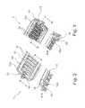
- FIG. 2 shows a model view of a base of a heat exchanger in a view from above
- FIG. 3 shows a model view of the base of the heat exchanger in a view from below
- FIG. 4 shows a cutout of a base of the heat exchanger with an elevation
- FIG. 5 shows a section through a base of a heat exchanger.
- FIG. 1 illustrates a heat exchanger 1 , in particular a coolant cooler, which consists of a block 2 which is arranged between two collecting tanks 3 , 4 , wherein the first collecting tank 3 can serve for the entry of a medium to be cooled into the heat exchanger 1 , whereas the cooled medium can leave the heat exchanger 1 through the second collecting tank 4 .
- the first collecting tank can also comprise an inlet and an outlet, whereas the second collecting tank then merely brings about a deflection without discharge.
- Each collecting tank 3 , 4 here has a base 5 , 6 to which the block 2 , which is closed off by a side part 7 , is connected.
- the block 2 consists of a plurality of tubes 8 and a plurality of fins 9 , wherein tube 8 and fin 9 are preferably arranged in an alternating manner with respect to one another.
- the collecting tank 3 here has a connecting branch 10 into which the coolant which is conducted out of the internal combustion engine (not illustrated specifically) and is heated up by the latter flows, the coolant being conducted through the tubes 8 of the block 2 to the second collecting container 4 .
- a gaseous medium preferably air is conducted through the block 2 , in particular the fins 9 , said medium absorbing the heat of the cooling medium flowing through the tubes 8 and removing the heat from the heat exchanger 1 .
- the cooling medium is thereby cooled.
- the second collecting tank 4 of the heat exchanger 1 in which collecting tank the cooled cooling medium flows, comprises a further connecting branch 11 through which the cooling medium is discharged from the heat exchanger 1 and is supplied again to the internal combustion engine.
- the tubes 8 have a cross section similar to a rectangle. They are preferably folded. As is apparent from FIG. 2 , in which the base 5 of the collecting tank 3 is partially illustrated, the base 5 , which is likewise designed in a manner similar to a rectangle, has a plurality of rim holes 12 .
- the rim hole 12 is an opening which is likewise of rectangular design and into which the end of one tube 8 in each case is pushed.
- the first tube 8 a and the last tube 8 b of the block 2 which tubes both run directly parallel to an end side 13 of the base 5 , there is the problem that the fins 9 do not reach as far as the base 5 .
- the tubes 8 a , 8 b running parallel to the end sides of the base are unstable, and this can result in tube breakage.
- the base 5 has a channel-shaped circulating means 14 , into which the collecting tank 3 is inserted with the interposition of a seal.
- Said circulating means 14 is illustrated in FIG. 2 in the form of a hollow part facing outward.
- the circulating means 14 is separated from the tubes 8 a and 8 b by an expanded region 15 .
- an elevation 16 extends as far as the rim hole 12 a which receives the first tube 8 a directly opposite the end side 13 .
- Said elevation 16 firstly has the effect that the position of the tube 8 a , which extends in the first rim hole 12 a , is stabilized.
- the elevation 16 serves, when the tubes 8 are clamped to the base 5 , to guide the folded tube 8 a , which slightly spreads under the pressure of the block 2 , into the rim hole 12 a , as a result of which the end of the tube 8 a is again parallel to the rim hole 12 a and simple processing is possible.
- FIG. 3 illustrates the base 5 in a view from below, in which it is clear that the rim holes 12 have a collar-like design so that they can better surround the tubes 8 . From this view, in particular the section B-B, it is clear that the elevation 16 is stamped out of the base 5 .
- the base 5 is produced together with the rim holes 12 from sheet metal in a punching process.
- the elevation 16 which elevates on the side of the base 5 which is opposite the collecting tank 3 , extends as far as the first rim hole 12 a of the first tube 8 a . It is clear in particular from FIG. 4 b that the elevation 16 extends at a higher level than the formation of the rim hole 12 a . It is advantageous here that the elevation 16 , however, does not reduce the cross section of the rim hole 12 a , but rather keeps the latter constant, and therefore a tube of customary size can be inserted there. With the aid of this elevation 16 , the end of the tube 8 a is guided into the rim hole 12 a during installation. As a result, the tube end of the tube 8 a is aligned again with the rim hole 12 a , and therefore a probability of damage is reduced.
- the elevation 16 can be integrated in a simple manner into a punching tool. An alternating use of embodiments of the base 5 , 6 with and without an elevation is possible without each finishing machine of a block having to be adapted. A finishing machine of a block constitutes a tool in which the heat exchanger 1 is manufactured as a whole. The manufacturing sequences are therefore not changed for the production of a block.
- FIG. 5 shows an end region of the base 5 according to the invention, in which a channel-shaped groove is formed in an encircling manner as a circulating means 14 , in which the collecting tank (not illustrated) can be inserted by the collecting tank foot thereof with the interposition of a seal (not illustrated).
- Said circulating means 14 is formed as a U-shaped hollow part facing outward, wherein, in the center of the narrow sides, an oppositely curved region 20 is directly connected to the U-shaped hollow part 14 and can serve as a receptacle, for example, for a side part.
- the circulating means 14 is separated from the tube openings or from the rim holes 12 a by an expanded region 15 .
- an elevation extends as far as the rim hole 12 a which receives the first tube 8 a directly opposite the end side 13 .
Landscapes
- Engineering & Computer Science (AREA)
- Physics & Mathematics (AREA)
- Mechanical Engineering (AREA)
- Thermal Sciences (AREA)
- General Engineering & Computer Science (AREA)
- Geometry (AREA)
- Heat-Exchange Devices With Radiators And Conduit Assemblies (AREA)
Applications Claiming Priority (4)
| Application Number | Priority Date | Filing Date | Title |
|---|---|---|---|
| DE102011085479.7 | 2011-10-28 | ||
| DE102011085479A DE102011085479A1 (de) | 2011-10-28 | 2011-10-28 | Wärmeübertrager |
| DE102011085479 | 2011-10-28 | ||
| PCT/EP2012/071322 WO2013060882A1 (de) | 2011-10-28 | 2012-10-26 | Wärmeübertrager |
Publications (2)
| Publication Number | Publication Date |
|---|---|
| US20140262187A1 US20140262187A1 (en) | 2014-09-18 |
| US9810484B2 true US9810484B2 (en) | 2017-11-07 |
Family
ID=47189906
Family Applications (1)
| Application Number | Title | Priority Date | Filing Date |
|---|---|---|---|
| US14/354,895 Expired - Fee Related US9810484B2 (en) | 2011-10-28 | 2012-10-26 | Heat exchanger with header contact regions for tubes support |
Country Status (7)
| Country | Link |
|---|---|
| US (1) | US9810484B2 (zh) |
| EP (1) | EP2771636B1 (zh) |
| KR (1) | KR20140088582A (zh) |
| CN (1) | CN103890530B (zh) |
| BR (1) | BR112014010083A8 (zh) |
| DE (1) | DE102011085479A1 (zh) |
| WO (1) | WO2013060882A1 (zh) |
Cited By (1)
| Publication number | Priority date | Publication date | Assignee | Title |
|---|---|---|---|---|
| US10302373B2 (en) * | 2017-03-03 | 2019-05-28 | Denso International America, Inc | Heat exchanger |
Families Citing this family (6)
| Publication number | Priority date | Publication date | Assignee | Title |
|---|---|---|---|---|
| DE102014200864A1 (de) * | 2014-01-17 | 2015-07-23 | MAHLE Behr GmbH & Co. KG | Wärmeübertrager |
| DE102014213758A1 (de) | 2014-07-15 | 2016-01-21 | Mahle International Gmbh | Rohrboden und Wärmeübertrager |
| FR3036469B1 (fr) * | 2015-05-22 | 2017-06-09 | Valeo Systemes Thermiques | Plaque collectrice pour echangeur de chaleur, notamment pour vehicule automobile |
| FR3037643B1 (fr) * | 2015-06-22 | 2019-07-12 | Valeo Systemes Thermiques | Echangeur de chaleur et procede de fabrication associe |
| DE102018111556A1 (de) * | 2017-06-22 | 2018-12-27 | Hanon Systems | Wärmeübertrager |
| DE102020204845A1 (de) * | 2020-04-16 | 2021-10-21 | Mahle International Gmbh | Indirekter Ladeluftkühler |
Citations (22)
| Publication number | Priority date | Publication date | Assignee | Title |
|---|---|---|---|---|
| USRE31889E (en) * | 1973-10-25 | 1985-05-21 | Suddeutsche Kuhlerfabrik Julius Fr. Behr | Heat exchanger |
| US4546822A (en) * | 1982-11-01 | 1985-10-15 | Nippondenso Co., Ltd. | Heat exchanger with adhesive seals |
| CN1095022A (zh) | 1994-05-10 | 1994-11-16 | 瓦莱奥热舱公司 | 用于汽车的换热器 |
| EP0791797A1 (fr) | 1996-02-20 | 1997-08-27 | Valeo Thermique Moteur S.A. | Echangeur de chaleur à boîte à fluide brasée, en particulier pour véhicule automobile |
| EP0791791A1 (en) | 1995-09-22 | 1997-08-27 | Cristaleria Espanola S.A. | End sections of connections for mineral wool conduits of the "climaver plus" type |
| US5664625A (en) * | 1995-12-13 | 1997-09-09 | Valeo Thermique Moteur | Header plates for heat exchangers |
| US6988544B2 (en) * | 2002-12-26 | 2006-01-24 | Denso Corporation | Heat exchanger and method of manufacturing core plate |
| US20060144579A1 (en) * | 2005-01-06 | 2006-07-06 | Denso Corporation | Heat exchanger |
| US20060151158A1 (en) * | 2005-01-06 | 2006-07-13 | Denso Corporation | Heat exchanger |
| DE102006005421A1 (de) | 2005-02-03 | 2006-08-10 | Behr Gmbh & Co. Kg | Wärmetauscher |
| US20060185833A1 (en) | 2005-02-24 | 2006-08-24 | Viktor Brost | Heat exchanger and method of producing |
| CN1965209A (zh) | 2004-06-04 | 2007-05-16 | 贝洱两合公司 | 热交换器 |
| DE102005054043A1 (de) | 2005-11-12 | 2007-05-16 | Modine Mfg Co | Ganz-Metall-Wärmetauscher |
| CN101097122A (zh) | 2006-06-29 | 2008-01-02 | 株式会社电装 | 热交换器 |
| CN101103244A (zh) | 2005-01-26 | 2008-01-09 | 株式会社T.Rad | 热交换器 |
| CN101111736A (zh) | 2005-02-03 | 2008-01-23 | 贝洱两合公司 | 热交换器 |
| EP1972879A2 (de) | 2007-03-21 | 2008-09-24 | Behr GmbH & Co. KG | Wärmeübertrager, insbesondere Kühlmittelkühler für Kraftfahrzeuge |
| EP1995544A2 (de) | 2007-05-24 | 2008-11-26 | Behr GmbH & Co. KG | Wärmetauscher, insbesondere Ladeluftkühler oder Abgaskühler für eine Brennkraftmaschine eines Kraftfahrzeuges und dessen Herstellungsverfahren |
| DE102007033976A1 (de) | 2007-07-19 | 2009-01-22 | Behr Gmbh & Co. Kg | Verfahren zur Herstellung von Öffnungen in einem Bodenteil sowie Bodenteil, herstellbar nach dem Verfahren |
| DE102007052888A1 (de) | 2007-11-02 | 2009-05-07 | Behr Gmbh & Co. Kg | Wärmeübertrager, insbesondere für ein Fahrzeug |
| US20100051252A1 (en) * | 2007-07-11 | 2010-03-04 | Denso Corproation | Heat exchanger |
| DE102009035089A1 (de) | 2009-07-28 | 2011-02-03 | Behr Gmbh & Co. Kg | Wärmetauscher, Brennkraftmaschine und Verwendung des Wärmetauschers |
-
2011
- 2011-10-28 DE DE102011085479A patent/DE102011085479A1/de not_active Withdrawn
-
2012
- 2012-10-26 KR KR1020147014242A patent/KR20140088582A/ko not_active Application Discontinuation
- 2012-10-26 CN CN201280051940.2A patent/CN103890530B/zh not_active Expired - Fee Related
- 2012-10-26 US US14/354,895 patent/US9810484B2/en not_active Expired - Fee Related
- 2012-10-26 BR BR112014010083A patent/BR112014010083A8/pt not_active Application Discontinuation
- 2012-10-26 EP EP12787406.3A patent/EP2771636B1/de not_active Not-in-force
- 2012-10-26 WO PCT/EP2012/071322 patent/WO2013060882A1/de active Application Filing
Patent Citations (22)
| Publication number | Priority date | Publication date | Assignee | Title |
|---|---|---|---|---|
| USRE31889E (en) * | 1973-10-25 | 1985-05-21 | Suddeutsche Kuhlerfabrik Julius Fr. Behr | Heat exchanger |
| US4546822A (en) * | 1982-11-01 | 1985-10-15 | Nippondenso Co., Ltd. | Heat exchanger with adhesive seals |
| CN1095022A (zh) | 1994-05-10 | 1994-11-16 | 瓦莱奥热舱公司 | 用于汽车的换热器 |
| EP0791791A1 (en) | 1995-09-22 | 1997-08-27 | Cristaleria Espanola S.A. | End sections of connections for mineral wool conduits of the "climaver plus" type |
| US5664625A (en) * | 1995-12-13 | 1997-09-09 | Valeo Thermique Moteur | Header plates for heat exchangers |
| EP0791797A1 (fr) | 1996-02-20 | 1997-08-27 | Valeo Thermique Moteur S.A. | Echangeur de chaleur à boîte à fluide brasée, en particulier pour véhicule automobile |
| US6988544B2 (en) * | 2002-12-26 | 2006-01-24 | Denso Corporation | Heat exchanger and method of manufacturing core plate |
| CN1965209A (zh) | 2004-06-04 | 2007-05-16 | 贝洱两合公司 | 热交换器 |
| US20060144579A1 (en) * | 2005-01-06 | 2006-07-06 | Denso Corporation | Heat exchanger |
| US20060151158A1 (en) * | 2005-01-06 | 2006-07-13 | Denso Corporation | Heat exchanger |
| CN101103244A (zh) | 2005-01-26 | 2008-01-09 | 株式会社T.Rad | 热交换器 |
| CN101111736A (zh) | 2005-02-03 | 2008-01-23 | 贝洱两合公司 | 热交换器 |
| DE102006005421A1 (de) | 2005-02-03 | 2006-08-10 | Behr Gmbh & Co. Kg | Wärmetauscher |
| US20060185833A1 (en) | 2005-02-24 | 2006-08-24 | Viktor Brost | Heat exchanger and method of producing |
| DE102005054043A1 (de) | 2005-11-12 | 2007-05-16 | Modine Mfg Co | Ganz-Metall-Wärmetauscher |
| CN101097122A (zh) | 2006-06-29 | 2008-01-02 | 株式会社电装 | 热交换器 |
| EP1972879A2 (de) | 2007-03-21 | 2008-09-24 | Behr GmbH & Co. KG | Wärmeübertrager, insbesondere Kühlmittelkühler für Kraftfahrzeuge |
| EP1995544A2 (de) | 2007-05-24 | 2008-11-26 | Behr GmbH & Co. KG | Wärmetauscher, insbesondere Ladeluftkühler oder Abgaskühler für eine Brennkraftmaschine eines Kraftfahrzeuges und dessen Herstellungsverfahren |
| US20100051252A1 (en) * | 2007-07-11 | 2010-03-04 | Denso Corproation | Heat exchanger |
| DE102007033976A1 (de) | 2007-07-19 | 2009-01-22 | Behr Gmbh & Co. Kg | Verfahren zur Herstellung von Öffnungen in einem Bodenteil sowie Bodenteil, herstellbar nach dem Verfahren |
| DE102007052888A1 (de) | 2007-11-02 | 2009-05-07 | Behr Gmbh & Co. Kg | Wärmeübertrager, insbesondere für ein Fahrzeug |
| DE102009035089A1 (de) | 2009-07-28 | 2011-02-03 | Behr Gmbh & Co. Kg | Wärmetauscher, Brennkraftmaschine und Verwendung des Wärmetauschers |
Non-Patent Citations (2)
| Title |
|---|
| German Search Report, DE 10 2011 085 479.7, dated Feb. 6, 2012, 8 pgs. |
| International Search Report, PCT/EP2012/071322, dated Mar. 7, 2013, 2 pgs. |
Cited By (1)
| Publication number | Priority date | Publication date | Assignee | Title |
|---|---|---|---|---|
| US10302373B2 (en) * | 2017-03-03 | 2019-05-28 | Denso International America, Inc | Heat exchanger |
Also Published As
| Publication number | Publication date |
|---|---|
| BR112014010083A2 (pt) | 2017-06-13 |
| EP2771636B1 (de) | 2016-01-06 |
| EP2771636A1 (de) | 2014-09-03 |
| KR20140088582A (ko) | 2014-07-10 |
| CN103890530A (zh) | 2014-06-25 |
| WO2013060882A1 (de) | 2013-05-02 |
| US20140262187A1 (en) | 2014-09-18 |
| BR112014010083A8 (pt) | 2017-06-20 |
| CN103890530B (zh) | 2016-08-17 |
| DE102011085479A1 (de) | 2013-05-02 |
Similar Documents
| Publication | Publication Date | Title |
|---|---|---|
| US9810484B2 (en) | Heat exchanger with header contact regions for tubes support | |
| US10203160B2 (en) | Cooling module | |
| KR101488131B1 (ko) | 열 교환기용 튜브 | |
| US9318782B2 (en) | Temperature control device for the temperature control of a battery and method for the production of a temperature control device | |
| US10393450B2 (en) | Collector plate for a heat exchanger manifold | |
| US20100032149A1 (en) | Heat exchanger and method of manufacturing the same | |
| US10147668B2 (en) | Stacked cooler | |
| US20110139424A1 (en) | Heat exchanger | |
| CN105904960B (zh) | 冷却模块 | |
| US20160234975A1 (en) | Heat exchanger for cooling electric element | |
| US11181330B2 (en) | Heat exchanger | |
| KR101435665B1 (ko) | 쿨링모듈 | |
| KR101409176B1 (ko) | 응축기 및 라디에이터 조립체 | |
| KR20130143343A (ko) | 응축기 | |
| KR20160035825A (ko) | 라디에이터 및 콘덴서 조립체 | |
| KR101771152B1 (ko) | 응축기 | |
| KR20170104248A (ko) | 열교환기 | |
| KR20120095518A (ko) | 열교환기 | |
| KR20080075983A (ko) | 증발기 | |
| KR101389310B1 (ko) | 응축기 | |
| US20230052183A1 (en) | Heat exchanger | |
| US11274885B2 (en) | Collector box, sealing means and corresponding heat exchanger | |
| EP3872433A1 (en) | A heat exchanger and a header tank assembly therefor | |
| KR101960804B1 (ko) | 차량용 열교환기 | |
| KR101631572B1 (ko) | 응축기 |
Legal Events
| Date | Code | Title | Description |
|---|---|---|---|
| AS | Assignment |
Owner name: BEHR GMBH & CO. KG, GERMANY Free format text: ASSIGNMENT OF ASSIGNORS INTEREST;ASSIGNORS:GRUBER, TIMO;HELMS, WERNER;NGUYEN, CHI-DUC;AND OTHERS;SIGNING DATES FROM 20140325 TO 20140403;REEL/FRAME:033852/0193 |
|
| AS | Assignment |
Owner name: MAHLE INTERNATIONAL GMBH, GERMANY Free format text: ASSIGNMENT OF ASSIGNORS INTEREST;ASSIGNOR:BEHR GMBH & CO. KG;REEL/FRAME:043431/0681 Effective date: 20170822 |
|
| STCF | Information on status: patent grant |
Free format text: PATENTED CASE |
|
| FEPP | Fee payment procedure |
Free format text: MAINTENANCE FEE REMINDER MAILED (ORIGINAL EVENT CODE: REM.); ENTITY STATUS OF PATENT OWNER: LARGE ENTITY |
|
| LAPS | Lapse for failure to pay maintenance fees |
Free format text: PATENT EXPIRED FOR FAILURE TO PAY MAINTENANCE FEES (ORIGINAL EVENT CODE: EXP.); ENTITY STATUS OF PATENT OWNER: LARGE ENTITY |
|
| STCH | Information on status: patent discontinuation |
Free format text: PATENT EXPIRED DUE TO NONPAYMENT OF MAINTENANCE FEES UNDER 37 CFR 1.362 |
|
| FP | Lapsed due to failure to pay maintenance fee |
Effective date: 20211107 |