US9800301B2 - Antenna sharing device for wireless access node systems in wireless communication network - Google Patents
Antenna sharing device for wireless access node systems in wireless communication network Download PDFInfo
- Publication number
- US9800301B2 US9800301B2 US14/845,955 US201514845955A US9800301B2 US 9800301 B2 US9800301 B2 US 9800301B2 US 201514845955 A US201514845955 A US 201514845955A US 9800301 B2 US9800301 B2 US 9800301B2
- Authority
- US
- United States
- Prior art keywords
- signal
- access node
- wireless access
- node system
- reception
- Prior art date
- Legal status (The legal status is an assumption and is not a legal conclusion. Google has not performed a legal analysis and makes no representation as to the accuracy of the status listed.)
- Active, expires
Links
Images


Classifications
-
- H—ELECTRICITY
- H04—ELECTRIC COMMUNICATION TECHNIQUE
- H04B—TRANSMISSION
- H04B7/00—Radio transmission systems, i.e. using radiation field
- H04B7/02—Diversity systems; Multi-antenna system, i.e. transmission or reception using multiple antennas
- H04B7/04—Diversity systems; Multi-antenna system, i.e. transmission or reception using multiple antennas using two or more spaced independent antennas
- H04B7/0413—MIMO systems
-
- H—ELECTRICITY
- H04—ELECTRIC COMMUNICATION TECHNIQUE
- H04B—TRANSMISSION
- H04B1/00—Details of transmission systems, not covered by a single one of groups H04B3/00 - H04B13/00; Details of transmission systems not characterised by the medium used for transmission
- H04B1/38—Transceivers, i.e. devices in which transmitter and receiver form a structural unit and in which at least one part is used for functions of transmitting and receiving
- H04B1/40—Circuits
-
- H—ELECTRICITY
- H04—ELECTRIC COMMUNICATION TECHNIQUE
- H04B—TRANSMISSION
- H04B7/00—Radio transmission systems, i.e. using radiation field
- H04B7/02—Diversity systems; Multi-antenna system, i.e. transmission or reception using multiple antennas
- H04B7/04—Diversity systems; Multi-antenna system, i.e. transmission or reception using multiple antennas using two or more spaced independent antennas
-
- H—ELECTRICITY
- H04—ELECTRIC COMMUNICATION TECHNIQUE
- H04W—WIRELESS COMMUNICATION NETWORKS
- H04W88/00—Devices specially adapted for wireless communication networks, e.g. terminals, base stations or access point devices
- H04W88/08—Access point devices
Definitions
- a mainly used frequency band is a band of 800 MHz or 900 MHz (for example, 698 to 940 MHz, hereinafter, referred to as “a first frequency band”) that is a relatively low frequency band, a band of 1.8 GHz or 2.1 GHz (for example, 1.71 to 2.17 GHz, hereinafter, referred to as “a second frequency band”) that is a relatively high frequency band, and a band of 2.3 GHz (for example, 2.3 to 2.7 GHz, hereinafter, referred to as “a third frequency band”) that is a relatively high frequency band.
- a first frequency band a band of 800 MHz or 900 MHz (for example, 698 to 940 MHz, hereinafter, referred to as “a first frequency band”) that is a relatively low frequency band
- a band of 1.8 GHz or 2.1 GHz for example, 1.71 to 2.17 GHz, hereinafter, referred to as “a second frequency band”
- a band of 2.3 GHz for example, 2.3
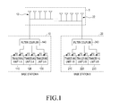
- FIG. 1 is a block diagram illustrating an example of wireless access node systems for each of a plurality of business operators representing a general antenna installation state, and illustrates, for example, a base station system A 10 and a base station system B 20 which are wireless communication base stations of business operators A and B.
- the base station system A 10 and the base station system B 20 may be general wireless communication base stations taking charge of a relatively wide area, but in the example of FIG. 1 , the base station system A 10 and the base station system B 20 are installed in each floor of a building, such that the base station system A 10 and the base station system B 20 correspond to a relay station or a small base station installed in a specific shadow area 1 .
- each of the base station system A 10 and the base station system B 20 may include, for example, communication equipment of the first to third bands.
- sub bands are differently allocated for each of the business operators in each of the first to third bands, so that the base station system A 10 includes transceiving units 1 -A, 2 -A, and 3 -A, 110 , 120 , and 130 for processing transceiving signals of bands 1 -A, 2 -A, and 3 -A.
- the base station system B 20 includes transceiving units 1 -B, 2 -B, and 3 -B 210 , 220 , and 230 for processing transceiving signals of bands 1 -B, 2 -B, and 3 -B.
- the base station system B 20 also includes a filter coupler 240 for distributing and coupling transmission and reception signals between the transceiving units 1 -B, 2 -B, and 3 -B 210 , 220 , and 230 and one or more base station antennas B 22 installed in the shadow area 1 .
- FIG. 1 is the example implemented by a 1Transfer 1Receive (1T1R) scheme, not the MIMO scheme. That is, for example, only a first transception path (path 1 ) P 1 is connected with the filter coupler 140 in the transceiving units 1 -A, 2 -A, and 3 -A 110 , 120 , and 130 of the base station system A 10 .
- path 1 path 1
- an apparatus for sharing antennas of wireless access node systems in a wireless communication network including a wireless access node system A and a wireless access node system B, each of which includes one or more transceiving units for processing transmission/reception signals of one or more frequency band
- the apparatus including: a Multiple Input Multiple Output (MIMO) coupler A that connects a signal of a first transceiving path among MIMO paths of the one or more transceiving units of the wireless access node system A and a signal of a second transceiving path among MIMO paths of the one or more transceiving units of the wireless access node system B with an antenna of the wireless access node system A; and a MIMO coupler B that connects a signal of a first transceiving path among the MIMO paths of the one or more transceiving units of the wireless access node system B and a signal of a second transceiving path among the MIMO paths of the one or more transceiving units of
- the directional coupler module A may include first and second directional couplers of a broadband, and upper and lower Band Pass Filters (BPFs) having a filtering characteristic of a signal band of the second transceiving path of the wireless access node system B installed in signal paths between the first and second directional couplers, respectively, and the directional coupler module B may include first and second directional couplers of a broadband, and upper and lower BPFs having a filtering characteristic of a signal band of the second transceiving path of the wireless access node system A installed in signal paths between the first and second directional couplers, respectively.
- BPFs Band Pass Filters
- the wireless access node system A may include at least transceiving units 1 -A and 2 -A for processing transceiving signals of at least bands 1 -A and 2 -A and a first path filter coupler coupling and distributing a signal of a first transceiving path of the MIMO paths of the transceiving units 1 -A and 2 -A, and provides a signal of a second transceiving path of the MIMO paths of any one of the transceiving units 1 -A and 2 -A to the outside
- the wireless access node system B may include at least transceiving units 1 -B and 2 -B for processing transceiving signals of at least bands 1 -B and 2 -B and a filter coupler coupling and distributing a signal of a first transceiving path of the MIMO paths of the transceiving units 1 -B and 2 -B, and provides a signal of a second transceiving path of the MIMO paths of any one of the transceiving units
- a n apparatus for sharing antennas of wireless access node systems in a wireless communication network including wireless access node system A and wireless access node system B, each of which includes one or more transceiving units for processing transmission/reception signals of one or more frequency bands
- the apparatus including: a directional coupler module A that allows a transmission signal provided through a first transceiving path among Multiple Input Multiple Output (MIMO) paths of the one or more transceiving units of the wireless access node system A to pass therethrough with a total-reflection characteristic, allows a transmission signal of a second transceiving path among MIMO paths of the one or more transceiving units of the wireless access node system B to pass therethrough, synthesizes both signals, and outputs the synthesized signal to an antenna of the wireless access node system A; and a MIMO coupler A including a reception signal processing circuit providing a part of the reception signals of the antenna of the wireless access node system A through the second transce
- MIMO Multiple Input Multiple Output
- the directional coupler module A may have a broadband characteristic capable of processing entire signal processing bands of the wireless access node systems A and B, and include first and second directional couplers of a broadband, and upper and lower transmission Band Pass Filters (BPFs) having a filtering characteristic of a transmission signal band of the second transmission path of the wireless access node system B installed in signal paths between the first and second directional couplers.
- BPFs Band Pass Filters
- the reception signal processing circuit may include: a coupler that couples and outputs a part of reception signals of the antenna of the wireless access node system A; and a duplexer that is installed in a connection path between the directional coupler module A and the wireless access node system B, and couples the reception signal provided from the coupler and the transmission signal transmitted by the wireless access node system B, and divides the reception signal provided from the coupler from the transmission signal transmitted by the wireless access node system B.
- the reception signal processing circuit may include: a coupler that couples and outputs a part of reception signals of the antenna of the wireless access node system A; a first reception BPF that filters and outputs the reception signal provided from the coupler according to a predetermined reception signal band; and an isolator that provides the signal output from the first reception BPF to the directional coupler module A, and the directional coupler module A may receive the reception signal provided through the isolator, totally reflect the received signal, and transmit the totally reflected signal to the wireless access node system B.
- the reception signal processing circuit may include: an attenuator that attenuates the reception signal provided by the wireless access node system A; and a duplexer that is installed in a connection path between the directional coupler module A and the wireless access node system B, and couples the reception signal provided from the attenuator and the transmission signal transmitted by the wireless access node system B, and divides the reception signal provided from the attenuator from the transmission signal transmitted by the wireless access node system B.
- FIG. 2 is a block diagram for an apparatus for sharing antennas of wireless access node systems and related devices according to a first exemplary embodiment of the present invention.
- FIG. 3 is a block diagram for one structure example considerable for performing an operation corresponding to an MIMO coupler in FIG. 2 .
- FIG. 5 is a detailed block diagram of the MIMO couplers of FIG. 2 .
- FIG. 6 is a detailed block diagram of a MIMO coupler in an apparatus for sharing antennas of wireless access node systems according to a second exemplary embodiment of the present invention.
- FIG. 7 is a diagram of a modified example of FIG. 6 .
- FIG. 8 is a detailed block diagram of a MIMO coupler in an apparatus for sharing antennas of wireless access node systems according to a third exemplary embodiment of the present invention.
- FIG. 9 is a detailed block diagram of a MIMO coupler in an apparatus for sharing antennas of wireless access node systems according to a fourth exemplary embodiment of the present invention.
- FIG. 11 is a block diagram for an apparatus for sharing antennas of wireless access node systems and related devices according to a sixth exemplary embodiment of the present invention.
- FIG. 12 is a detailed block diagram of an MIMO coupler of FIG. 11 .
- FIG. 2 is a block diagram for an apparatus for sharing antennas of wireless access node systems and related devices according to a first exemplary embodiment of the present invention, similar to the example of the related art illustrated in FIG. 1 , and FIG. 2 illustrates a base station system A 10 and a base station system B 20 corresponding to wireless communication base stations of business operators A and B.
- each of the base station system A 10 and the base station system B 20 may include, for example, communication equipment of the first to third bands.
- the base station system A 10 includes 1 -A, 2 -A, and 3 -A transceiving units 110 , 120 , and 130 for processing transmission/reception signals of bands 1 -A, 2 -A, and 3 -A
- the base station system B 20 includes transceiving units 1 -B, 2 -B, and 3 -B 210 , 220 , and 230 for processing transmission/reception signals of bands 1 -B, 2 -B, and 3 -B.
- the base station system A 10 and the base station system B 20 are implemented by, for example, a Multiple Input Multiple Output (MIMO) system of 2Transfer 2Receive (2T2R), and antennas required to be additionally provided to this end have structures for sharing and utilizing the antennas of the other business operators (that is, the other base stations) with each other according to the characteristic of the present invention.
- MIMO Multiple Input Multiple Output
- a transmission signal through a second transceiving path P 2 among the MIMO paths of a transceiving unit, that is, the transceiving unit 1 -A 110 in the example of FIG. 2 , of at least one band of the base station system A 10 is provided to the MIMO coupler B 40
- a transmission signal through the second transceiving path P 2 among the MIMO paths of a transceiving unit, that is, the transceiving unit 1 -B 210 in the example of FIG. 2 , of at least one band of the base station system B 20 is provided to the MIMO coupler A 30 .
- a reception operation is performed by a reverse process of the transmission operation. That is, the MIMO coupler A 30 distributes a signal of a band allocated to the base station system A 10 among the signals received by the base station antenna A 12 and provides the signal to the filter coupler 140 of the base station A, and distributes a signal of a band allocated to the base station system B 20 among the signals received by the base station antenna A 12 and finally provides the signal to the second transception path of the transceiving unit 1 -B 210 of the base station system B 20 .
- the filter coupler 140 of the base station system A 10 distributes the reception signals for each frequency band and provides the distributed signals to the corresponding the transceiving units 1 -A, 2 -A, and 3 -A 110 , 120 , and 130 , respectively.
- the MIMO coupler B 40 distributes a signal of a band allocated to the base station system B 20 among the signals received by the base station antenna B 22 and provides the signal to the filter coupler 240 of the base station B, and distributes a signal of a band allocated to the base station system A 10 among the signals received by the base station antenna B 22 to the base station system A 10 .
- FIG. 3 is a block diagram for one structure example considerable for performing an operation corresponding to an MIMO coupler in FIG. 2 , and for example, an action corresponding to the MIMO coupler A 30 of FIG. 2 may be performed.
- a MIMO coupler 30 - 1 illustrated in FIG. 3 may be configured based on a structure of the filter coupler including filter units corresponding to frequency bands of passing signals, respectively.
- the MIMO coupler 30 - 2 includes a second/third BPF 310 for filtering a signal of a different band other than the first frequency band, that is, the signal of the second/third frequency band, a lower first BPF 320 and an upper first BPF 322 for filtering the signals of the first frequency band (that is, the band including all of the frequency bands 1 -A and 1 -B), and a directional coupler module 330 having a characteristic of allowing the signal of the frequency band 1 -B in the first frequency band to pass therethrough.
- the MIMO coupler 30 - 2 is configured so that the signal transmitted by the base station system A 10 is distributed and input into the second/third BPF 310 and the lower first BPF 320 , and the signal received by the base station antenna A 12 is distributed and input into the second/third BPF 310 and the upper first BPF 322 .
- the directional coupler module 330 divides the first frequency band signal into signals of the frequency bands 1 -A and 1 -B, totally reflects the reception signal of the frequency band 1 -A and outputs the totally reflected reception signal to the lower first BPF 320 , allows the reception signal of the frequency band 1 -B to pass therethrough, and outputs the passing reception signal to the base station system B 20 .
- the directional coupler module 330 includes first and second directional couplers 331 and 332 processing the signals of the first frequency band, respectively, and upper and lower BPFs 1 -B 333 and 334 of the frequency band 1 -B installed in the signal paths between the first and second directional couplers 331 and 332 , respectively.
- the signals input into a number one terminal or a number two terminal have a predetermined phase difference (for example, 90 degrees), and each of the first and second directional couplers 331 and 332 distributes and outputs the signal input into the number one terminal or the number two terminal to a number three terminal and a number four terminal, respectively.
- the first and second directional couplers 331 and 332 synthesize the signals input into the number three terminal and the number four terminal according to phase differences and output the synthesized signal to the number one terminals or the number two terminals.
- the number one terminal of the first directional coupler 331 is connected with the upper first BPF 322
- the number two terminal of the first directional coupler 331 is connected with the lower first BPF 320 .
- the signals input into the number two terminal of the first directional coupler 331 through the lower first BPF 320 have predetermined phase differences from each other and are distributed and output to the number three terminal and the number four terminal, and the frequency band of the corresponding distributed signals is the frequency band 1 -A, so that the distributed signals are totally reflected by the upper and lower BPFs 1 -B 333 and 334 and re-input into the number three terminal and the number four terminal.
- the signals re-input into the number three terminal and the number four terminal have a predetermined phase difference (for example, 90 degrees), so that the signals are finally synthesized and output to the number one terminal.
- the signals input into the number four terminal of the second directional coupler 332 have a predetermined phase difference from each other (for example, 90 degrees) and are distributed and output to the number one terminal and the number two terminal, and the frequency band of the corresponding distributed signals is the frequency band 1 -B, so that the distributed signals pass through the upper and lower BPFs 1 -B 333 and 334 and are input into the number three terminal and the number four terminal of the first directional coupler 331 , and are finally synthesized and output to the number one terminal of the first directional coupler 331 .
- the configuration illustrated in FIG. 4 may be easily manufactured when a product is implemented compared to the configuration illustrated in FIG. 3 , but still is somewhat complex, in that the requirement of the filter structure in which the second/third BPF 310 and the lower and upper first BPFs 320 and 322 are combined, and a relatively large number of elements needs to be provided.
- FIG. 5 is a detailed block diagram of the MIMO couplers, that is, the MIMO coupler A 30 and the MIMO coupler B 40 , of FIG. 2 .
- the MIMO coupler A 30 and the MIMO coupler B 40 illustrated in FIG. 5 represent configurations, in which the problem in the implementation of the MIMO coupler 30 - 2 illustrated in FIG. 4 is somewhat solved.
- the MIMO coupler A 30 and the MIMO coupler B 40 are implemented as directional coupler modules, that is, directional coupler modules A and B 340 and 440 , respectively.
- the directional coupler module 330 illustrated in FIG. 4 is designed so as to process the signal of the first frequency band (for example, the band of 800 MHz), but the directional coupler modules A and B 340 and 440 illustrated in FIG. 5 are designed to have a broadband characteristic capable of processing all of the signals of the first to third frequency bands, for example, the bands of 800 MHz, 1.8 GHz, and 2 GHZ.
- the present exemplary embodiment has been described based on the bands of 800 MHz, 1.8 GHz, and 2 GHZ as an example, but those skilled in the art may sufficiently infer that the MIMO coupler may be designed so that the operation is performed with a band larger or smaller than the bands.
- the directional coupler module A 340 is configured to receive signals of all of the bands transmitted by the base station system A 10 through one input/output port, and connected to the base station system B 20 through another input/output port. In this case, the directional coupler module A 340 is configured to totally reflect the transmission signal of the base station system A 10 , allows the transmission signal of the base station system B 20 to pass therethrough, synthesizes both signals, and outputs the synthesized signal to the base station antenna A 12 .
- the directional coupler module A 340 includes first and second directional couplers 341 and 342 of a broadband processing the signals of the first to third frequency bands, respectively, and upper and lower BPFs 1 -B 343 and 344 of the frequency band 1 -B installed in signal paths between the first and second directional couplers 341 and 342 , respectively.
- the signals input into the number four terminal of the second directional coupler 342 have a predetermined phase difference (for example, 90 degrees) from each other and are distributed and output to the number one terminal and the number two terminal, and the frequency band of the corresponding distributed signals is the frequency band 1 -B, so that the distributed signals pass through the upper and lower BPFs 1 -B 343 and 344 and are input into the number three terminal and the number four terminal of the first directional coupler 341 , and are finally synthesized and output to the number one terminal of the first directional coupler 341 .
- a predetermined phase difference for example, 90 degrees
- the directional coupler modules A and B 340 and 440 process the reception signals, as well as the transmission signals of the base station system A and B 10 and 20 , and in this case, it can be seen that the upper and lower BPFs 1 -B 343 and 344 of the directional coupler module A 340 need to have a filter structure passing through all of the transmission and reception bands of the band 1 -B, and similarly, the upper and lower BPFs 1 -A 443 and 444 of the directional coupler module B 440 need to have a filter structure passing through all of the transmission and reception bands of the band 1 -A.
- each of the upper and lower BPFs 1 -B 343 and 344 may have a structure, in which the pass filters of the transmission band and the reception band in the band 1 -B are combined, and similarly, each of the upper and lower BPFs 1 -A 443 and 444 may have a structure, in which the passing filters of the transmission band and the reception band in the band 1 -A are combined.
- the aforementioned structure is demanded in a high performance transmission and reception filter, and may still have problems in a complex configuration, an installation space and manufacturing costs.
- the upper and lower BPFs 1 -B 343 and 344 may have a pass filter structure processing only the transmission band in the band 1 -B, and similarly, each of the upper and lower BPFs 1 -A 443 and 444 may have a pass filter structure processing only the transmission band in the band 1 -A.
- the directional coupler module A 340 has the configuration which is capable of processing all of the transmission signal and the reception signal of the base station system A 10 but is not capable of processing the reception signal of the base station system B 20
- the directional coupler module B 440 has the configuration which allows the transmission signal and the reception signal of the base station system B 20 to pass therethrough, but is not capable of processing the reception signal of the base station system A 10 .
- the aforementioned configuration may be sufficiently utilized when the antenna sharing system is implemented according to the 2T1R scheme.
- the directional coupler module A 530 is configured to totally reflect the transmission signal of the base station system A 10 , allows the transmission signal of the base station system B 20 to pass therethrough, synthesizes both signals, and outputs the synthesized signal to the base station antenna A 12 through the sharing port Pc.
- the directional coupler module A 530 when the signal received by the base station antenna A 12 is input into the directional coupler module A 530 through the coupler 550 , the directional coupler module A 530 totally reflects the signal and outputs the totally reflected signal to the base station system A 10 .
- the directional coupler module A 530 includes first and second directional couplers 531 and 532 of a broadband processing the signals of the first to third frequency bands, respectively, and upper and lower transmission BPF 1 -Bs 533 and 534 of the frequency band 1 -B installed in signal paths between the first and second directional couplers 531 and 532 , respectively.
- the signals input into the number two terminal of the first directional coupler 531 are distributed and output to the number three terminal and the number four terminal while having a predetermined phase difference (for example, 990 degrees ⁇ from each other, and the frequency bands of the corresponding distributed signals are the frequency bands 1 -A, 2 -A, and 3 -A, so that the distributed signals are totally reflected by the upper and lower transmission BPFs 1 -B 533 and 534 and re-input into the number three terminal and the number four terminal.
- the signals re-input into the number three terminal and the number four terminal have a predetermined phase difference (for example, 90 degrees), so that the signals are synthesized and output to the number one terminal as a result.
- FIG. 7 is a diagram illustrating a modified example of FIG. 6 , and illustrates a MIMO coupler A 52 having a structure slightly modified from the configuration of the MIMO coupler A 50 illustrated in FIG. 6 .
- the MIMO coupler A 52 includes a directional coupler module A 540 similar to the example of FIG. 6 , and differently from the directional coupler module A 530 illustrated in FIG. 6 , the directional coupler module A 540 illustrated in FIG. 7 is designed to have a characteristic (of a relatively narrow band) capable of processing a signal of the first frequency band, for example, the band of 800 MHz, and thus first and second directional couplers 541 and 542 inside the directional coupler module A 540 are designed to have the characteristic of a narrow band.
- the structure may be slightly similar to the structure illustrated in FIG. 4 , but is different from the structure illustrated in FIG. 4 in allowing only the transmission band of the band 1 -B to pass therethrough.
- the directional coupler module A 540 is capable of processing a signal of the first frequency band, so that filter structures 510 , 520 , and 522 separating the second/third frequency band and the first frequency band and providing only the first frequency band to the directional coupler module A 540 are provided at a front end of the directional coupler module A, similar to the example illustrated in FIG. 4 .
- the directional coupler module 540 is configured be connected with the lower and upper first BPF 520 and 522 through input/output ports, respectively, and is connected with the base station system B 20 through another input/output port via the duplexer 560 .
- the directional coupler module 540 is configured to totally reflect the transmission signal of the base station system A 10 input through the lower first BPF 520 , allow the transmission signal of the base station system B 20 to pass therethrough, and synthesize both signals to output the synthesized signal to the upper first BPF 522 .
- the directional coupler module A 530 further includes a configuration for receiving the reception signal provided through the isolator 670 , totally reflecting the received reception signal, and transmitting the totally reflected signal to the base station system B 20 through a second port P 2 .
- the coupler 550 , the first reception BPF 660 , and the isolator 670 are provided as reception signal processing circuits.
- the MIMO coupler A 60 according to the third exemplary embodiment of the present invention may be configured as described above, and a MIMO coupler B may be configured in the similar manner.
- a configuration and an operation principle of the MIMO coupler B is the same as those of the directional coupler module A 530 except that a signal of the base station A and a signal of the base station B are processed in an opposite manner.
- the duplexer 760 may have a filter combination structure including a first reception BPF 761 for filtering the reception signal provided by the transceiving unit 1 -A 110 through a third port P 3 and a first transmission BPF 762 for filtering the transmission signal transmitted by the base station system B 20 .
- the transceiving unit 1 -A 110 of the base station system A 10 may include a duplexer DUP ( 111 and 112 ) having a filter combination structure including a first reception BPF 111 and a first transmission BPF 112 for combining and separating the transmission and reception signals.
- the reception signal filtered by the first reception BPF 111 of the duplexer DUP is amplified by a low noise amplifier (LAN) 113 , and a part of the output signals of the low noise amplifier 113 is distributed through a distributor (2way distributor) 114 , and then output to the outside through an auxiliary port Pa separately provided in the corresponding transceiving unit 1 -A 110 .
- LAN low noise amplifier
- the reception signal of the base station system B 20 is once received in the transceiving unit 1 -A 110 of the base station system A 10 through the MIMO coupler A 70 , and then is provided to the MIMO coupler A 70 again, and is re-transmitted to the base station system B 20 .
- the MIMO coupler A 70 according to the fourth exemplary embodiment of the present invention may be configured as described above, and a MIMO coupler B may be configured in the similar manner.
- a configuration and an operation principle of the MIMO coupler B are the same as those of the directional coupler module A 530 except that a signal of the base station A and a signal of the base station B are processed in an opposite manner.
- FIG. 10 is a detailed block diagram of a MIMO coupler in an apparatus for sharing antennas of wireless access node systems according to a fifth exemplary embodiment of the present invention.
- a MIMO coupler A 80 according to the fifth exemplary embodiment of the present invention includes: a directional coupler module A 530 having the same configuration as that of the directional coupler module A 530 illustrated in FIG.
- the directional coupler module A 530 further includes a configuration for receiving the reception signal provided through the isolator 870 , totally reflecting the received reception signal, and transmitting the totally reflected signal to the base station system B 20 through a second port P 2 .
- the reception signal provided through the isolator 870 is input into a number three terminal of the second directional coupler 532 of the directional coupler module A 530 .
- the signals input into the number three terminal of the second directional coupler 532 are distributed and output to a number one terminal and a number two terminal while having a predetermined phase difference (for example, 90 degrees) from each other, and a frequency band of the corresponding distributed signals is the first frequency band, so that the distributed signals are totally reflected by upper and lower transmission BPFs 1 -B 533 and 534 and re-input into the number one terminal and the number two terminal.
- the transceiving unit 1 -A 110 of the base station system A 10 has the same configuration as that of the example of FIG. 9 , so that the transceiving unit 1 -A 110 is configured to output a part of the reception signals to the outside through a separately provided auxiliary port Pa.
- the signal output from the auxiliary port Pa of the transceiving unit 1 -A 110 is attenuated by an attenuator 790 , and then is provided to the first reception BPF 860 through the third port P 3 of the MIMO coupler A 80 .
- the MIMO coupler A 80 according to the fifth exemplary embodiment of the present invention may be configured as described above, and a MIMO coupler B may be configured in the similar manner.
- a configuration and an operation principle of the MIMO coupler B is the same as those of the directional coupler module A 530 except that a signal of the base station A and a signal of the base station B are processed in an opposite manner.
- the transmission signals processed by the transceiving units 1 -A, 2 -A, and 3 -A 1510 , 1520 , and 1530 of the base station system A 1050 through a first transceiving path P 1 in a MIMO path are coupled by a first path filter coupler 1541 and provided to a MIMO coupler A 1070 similar to the first exemplary embodiment, but the transmission signals processed by the transceiving units 1 -A, 2 -A, and 3 -A 1510 , 1520 , and 1530 through a second transceiving path P 2 in the MIMO path are coupled by a second path filter coupler 1542 and provided to a MIMO coupler B 1080 .
- the transmission signals processed by the transceiving units 1 -B, 2 -B, and 3 -B 1610 , 1620 , and 1630 of the base station system B 1060 through the first transceiving path P 1 in a MIMO path are coupled by a first path filter coupler 1641 and provided to the MIMO coupler B 1080
- the transmission signals processed by the transceiving units 1 -B, 2 -B, and 3 -B 1610 , 1620 , and 1630 of the base station system B 1060 through the second transceiving path P 2 in a MIMO path are coupled by a second path filter coupler 1642 and provided to the MIMO coupler A 1070 .
- the directional coupler module A 1740 is configured to receive signals of all of the bands transmitted by the base station system A 1050 through one input/output port, and connected to the base station system B 1060 through another input/output port. In this case, the directional coupler module A 1740 is configured to totally reflect the transmission signal of the base station system A 1050 , allow the transmission signal of the base station system B 1060 to pass therethrough, synthesize both signals, and output the synthesized signal to the base station antenna A 12 .
- the signals input into a number one terminal or a number two terminal have a predetermined phase difference (for example, 90 degrees), and each of the first and second directional couplers 1741 and 1742 distributes and outputs the signal input into the number one terminal or the number two terminal to a number three terminal and a number four terminal, respectively.
- the first and second directional couplers 1741 and 1742 synthesize the signals input into the number three terminal and the number four terminal according to phase differences and output the synthesized signal to the number one terminal or the number two terminal.
- the number one terminal of the first directional coupler 1741 is connected to base station system A 1050
- the number two terminal is connected to the base station antenna A 12 .
- the number four terminal of the second directional coupler 1742 is connected with the base station system B 1060 . Further, the number three terminal of the first directional coupler 1741 is connected with the number one terminal of the second direction coupler 1742 through the upper BPFs 1 -B/ 2 -B/ 3 -B 1743 , and the number four terminal of the first directional coupler 1741 is connected with the number two terminal of the second direction coupler 1742 through the lower BPFs 1 -B/ 2 -B/ 3 -B 1744 .
- a principle of the detailed configuration of the directional coupler module B 1840 is the same as that of the directional coupler module A 1740 except that a signal of the base station A and a signal of the base station B are processed in an opposite manner.
- the directional coupler module B 1840 includes first and second directional couplers 1841 and 1841 of a broadband processing the signals of the first to third frequency bands, respectively, and upper and lower BPFs 1 -A/ 2 -A/ 3 -A 1843 and 1844 of the base station frequency band A (that is, the frequency bands 1 -A, 2 -A, and 3 -A) installed in signal paths between the first and second directional couplers 1841 and 1842 , respectively.
- the signals input into a number one terminal or a number two terminal have a predetermined phase difference (for example, 90 degrees), and each of the first and second directional couplers 1841 and 1842 distributes and outputs the signal input into the number one terminal or the number two terminal to a number three terminal and a number four terminal, respectively.
- the first and second directional couplers 1841 and 1842 synthesize the signals input into the number three terminal and the number four terminal according to phase differences and output the synthesized signal to the number one terminal or the number two terminal.
- the number one terminal of the first directional coupler 1841 is connected to the base station system B 1060
- the number two terminal is connected to the base station antenna B 22 .
- the number four terminal of the second directional coupler 1842 is connected with the base station system A 1050 . Further, the number three terminal of the first directional coupler 1841 is connected with the number one terminal of the second direction coupler 1842 through the upper BPFs 1 -A/ 2 -A/ 3 -A 1843 , and the number four terminal of the first directional coupler 1841 is connected with the number two terminal of the second direction coupler 1842 through the lower BPFs 1 -A/ 2 -A/ 3 -A 1844 .
- each of the base station systems A and B includes three transceiving units for processing the frequency signals of three bands, but in another exemplary embodiment of the present invention, each of the base station systems A and B may include a plurality of transceiving units for processing frequency signals of two bands or four or more bands, and a configuration for processing the MIMO path of a part of or an entirety of the transceiving units. Further, in addition, each of the base station systems A and B may also include one transceiving unit for processing a frequency signal of one band, and in this case, the base station systems may not be required to include a filter coupler for coupling and distributing the signals of the plurality of transceiving units as illustrated in FIGS. 2, 6 , and the like.
- the directional coupler may be configured by using the 3 dB hybrid coupler, but in addition, the directional coupler may be configured by using a Magic-T coupler.
- a phase shifter for adjusting a phase of an input/output signal to be distributed and synthesized may be appropriately provided at the input/output terminal.
- the MIMO coupler of the present invention includes two couplers, for example, the MIMO coupler A 30 and the MIMO coupler B 40 for the base station system A 10 and the base station system B 20 , but in addition, a configuration, in which any one of the MIMO coupler A 30 and the MIMO coupler B 40 is installed, may be available, and the configuration may be usefully used.
- the apparatus for sharing antennas of wireless communication base stations may share antennas of base stations of a plurality of business operators, so that particularly, the present invention is appropriate to establish a system of a MIMO scheme, and it is possible to solve the problems in an increase in installation cost, difficulty in securing an antenna installation space, and non-efficiency of a management of the antenna due to overlapping installation of the plurality of antennas for each business operator in the related art.
Landscapes
- Engineering & Computer Science (AREA)
- Computer Networks & Wireless Communication (AREA)
- Signal Processing (AREA)
- Mobile Radio Communication Systems (AREA)
- Radio Transmission System (AREA)
- Transceivers (AREA)
Applications Claiming Priority (5)
| Application Number | Priority Date | Filing Date | Title |
|---|---|---|---|
| KR10-2013-0022719 | 2013-03-04 | ||
| KR1020130022719A KR20140108879A (ko) | 2013-03-04 | 2013-03-04 | 무선통신 네트워크에서 무선 접속 노드 시스템의 안테나 공용화 장치 |
| KR1020130046906A KR102058060B1 (ko) | 2013-04-26 | 2013-04-26 | 무선통신 네트워크에서 무선 접속 노드 시스템의 안테나 공용화 장치 |
| KR10-2013-0046906 | 2013-04-26 | ||
| PCT/KR2014/001763 WO2014137132A1 (ko) | 2013-03-04 | 2014-03-04 | 무선통신 네트워크에서 무선 접속 노드 시스템의 안테나 공용화 장치 |
Related Parent Applications (1)
| Application Number | Title | Priority Date | Filing Date |
|---|---|---|---|
| PCT/KR2014/001763 Continuation WO2014137132A1 (ko) | 2013-03-04 | 2014-03-04 | 무선통신 네트워크에서 무선 접속 노드 시스템의 안테나 공용화 장치 |
Publications (2)
| Publication Number | Publication Date |
|---|---|
| US20150381243A1 US20150381243A1 (en) | 2015-12-31 |
| US9800301B2 true US9800301B2 (en) | 2017-10-24 |
Family
ID=51491595
Family Applications (1)
| Application Number | Title | Priority Date | Filing Date |
|---|---|---|---|
| US14/845,955 Active 2034-07-11 US9800301B2 (en) | 2013-03-04 | 2015-09-04 | Antenna sharing device for wireless access node systems in wireless communication network |
Country Status (5)
| Country | Link |
|---|---|
| US (1) | US9800301B2 (ja) |
| EP (1) | EP2966785B1 (ja) |
| JP (1) | JP6174167B2 (ja) |
| CN (1) | CN105027462B (ja) |
| WO (1) | WO2014137132A1 (ja) |
Families Citing this family (4)
| Publication number | Priority date | Publication date | Assignee | Title |
|---|---|---|---|---|
| CN204559569U (zh) * | 2015-03-31 | 2015-08-12 | 京信通信技术(广州)有限公司 | 有源分布式天线系统及其中继端机 |
| CN106304106B (zh) * | 2015-06-26 | 2019-05-28 | 华为技术有限公司 | 信号传输装置及系统 |
| US10673518B2 (en) * | 2017-06-27 | 2020-06-02 | Wilson Electronics, Llc | Crossover isolation reduction in a signal booster |
| KR102122811B1 (ko) * | 2019-12-17 | 2020-06-15 | (주)이랑텍 | 5g공용 결합 우수 pimd 결합방식의 필터 및 필터링 방법 |
Citations (12)
| Publication number | Priority date | Publication date | Assignee | Title |
|---|---|---|---|---|
| US20060003808A1 (en) | 2002-10-19 | 2006-01-05 | Quintel Technology Limited | Mobile radio base station |
| CN1797971A (zh) | 2004-12-30 | 2006-07-05 | M/A-Com公司 | 双波段全双工移动无线电装置 |
| KR100711015B1 (ko) | 1999-12-21 | 2007-04-25 | 루센트 테크놀러지스 인크 | 무선 시스템 결합 장치 및 그 방법 |
| KR20080114104A (ko) | 2007-06-26 | 2008-12-31 | 주식회사 케이엠더블유 | 필터 컴바이너/디바이더 |
| US20090262669A1 (en) | 2008-04-18 | 2009-10-22 | Sanders Stuart B | Network interface device with shared antenna |
| US20100151907A1 (en) | 2008-12-11 | 2010-06-17 | At&T Mobility Ii Llc | Sharing antennas for increased multiple-input uplink reception |
| US20110069644A1 (en) | 2009-09-21 | 2011-03-24 | Kmw Inc. | Apparatus for Sharing a Wireless Communication Base Station |
| US20110092171A1 (en) | 2007-12-20 | 2011-04-21 | Delforce Greg | Signal combiner |
| KR20110098687A (ko) | 2010-02-26 | 2011-09-01 | 인터실 아메리카스 인코포레이티드 | 공유 안테나에 대한 대역내 간섭 저감 방법 및 시스템 |
| WO2012044969A1 (en) | 2010-10-01 | 2012-04-05 | Andrew Llc | Distributed antenna system for mimo signals |
| US20120329523A1 (en) | 2011-06-13 | 2012-12-27 | Lgc Wireless, Llc | Distributed antenna system architectures |
| US20130023304A1 (en) | 2008-02-20 | 2013-01-24 | Shankara Raghuraman | Method and system for sharing multiple antennas in mobile devices |
-
2014
- 2014-03-04 JP JP2015561267A patent/JP6174167B2/ja active Active
- 2014-03-04 CN CN201480009971.0A patent/CN105027462B/zh active Active
- 2014-03-04 WO PCT/KR2014/001763 patent/WO2014137132A1/ko active Application Filing
- 2014-03-04 EP EP14759726.4A patent/EP2966785B1/en active Active
-
2015
- 2015-09-04 US US14/845,955 patent/US9800301B2/en active Active
Patent Citations (15)
| Publication number | Priority date | Publication date | Assignee | Title |
|---|---|---|---|---|
| KR100711015B1 (ko) | 1999-12-21 | 2007-04-25 | 루센트 테크놀러지스 인크 | 무선 시스템 결합 장치 및 그 방법 |
| US20060003808A1 (en) | 2002-10-19 | 2006-01-05 | Quintel Technology Limited | Mobile radio base station |
| JP2006503465A (ja) | 2002-10-19 | 2006-01-26 | クインテル テクノロジー リミテッド | 移動無線基地局 |
| CN1797971A (zh) | 2004-12-30 | 2006-07-05 | M/A-Com公司 | 双波段全双工移动无线电装置 |
| US20060145781A1 (en) | 2004-12-30 | 2006-07-06 | M/A Com. Inc. | Dual band full duplex mobile radio |
| KR20080114104A (ko) | 2007-06-26 | 2008-12-31 | 주식회사 케이엠더블유 | 필터 컴바이너/디바이더 |
| US20110092171A1 (en) | 2007-12-20 | 2011-04-21 | Delforce Greg | Signal combiner |
| US20130023304A1 (en) | 2008-02-20 | 2013-01-24 | Shankara Raghuraman | Method and system for sharing multiple antennas in mobile devices |
| US20090262669A1 (en) | 2008-04-18 | 2009-10-22 | Sanders Stuart B | Network interface device with shared antenna |
| US20100151907A1 (en) | 2008-12-11 | 2010-06-17 | At&T Mobility Ii Llc | Sharing antennas for increased multiple-input uplink reception |
| US20110069644A1 (en) | 2009-09-21 | 2011-03-24 | Kmw Inc. | Apparatus for Sharing a Wireless Communication Base Station |
| JP2013504924A (ja) | 2009-09-21 | 2013-02-07 | ケーエムダブリュ・インコーポレーテッド | 無線通信基地局の共用化装置 |
| KR20110098687A (ko) | 2010-02-26 | 2011-09-01 | 인터실 아메리카스 인코포레이티드 | 공유 안테나에 대한 대역내 간섭 저감 방법 및 시스템 |
| WO2012044969A1 (en) | 2010-10-01 | 2012-04-05 | Andrew Llc | Distributed antenna system for mimo signals |
| US20120329523A1 (en) | 2011-06-13 | 2012-12-27 | Lgc Wireless, Llc | Distributed antenna system architectures |
Non-Patent Citations (3)
| Title |
|---|
| EP Search Report issued on Oct. 11, 2016 in corresponding European Patent Application No. 14759726.4. |
| First Office Action dated Jul. 3, 2017 in corresponding Chinese Patent Application No.: 2017062801950430. |
| JP Office Action issued on Sep. 26, 2016 in corresponding Japanese Patent Application No. 2015-561267. |
Also Published As
| Publication number | Publication date |
|---|---|
| EP2966785A1 (en) | 2016-01-13 |
| WO2014137132A1 (ko) | 2014-09-12 |
| CN105027462B (zh) | 2018-07-10 |
| CN105027462A (zh) | 2015-11-04 |
| EP2966785B1 (en) | 2018-11-21 |
| US20150381243A1 (en) | 2015-12-31 |
| JP2016515333A (ja) | 2016-05-26 |
| JP6174167B2 (ja) | 2017-08-02 |
| EP2966785A4 (en) | 2016-11-09 |
Similar Documents
| Publication | Publication Date | Title |
|---|---|---|
| US7941187B2 (en) | Apparatus for using a wireless communication base station in common | |
| US8027699B2 (en) | Systems and methods of band amplification with a shared amplifier | |
| US7346323B2 (en) | Diversity reception for co-siting base stations | |
| US8046027B2 (en) | Apparatus for using a wireless communication base station in common | |
| US9800301B2 (en) | Antenna sharing device for wireless access node systems in wireless communication network | |
| US11349510B2 (en) | Radio frequency front end module and communication device | |
| WO2008078103A2 (en) | Antenna system | |
| EP3065317B1 (en) | Co-frequency range combiner/splitter and multi-system combining platform | |
| EP2086244B1 (en) | Signal combination method, device and system having different system, same band and antenna sharing | |
| CN108933609B (zh) | Tdd/fdd可配置装置、方法、射频模块及通信设备 | |
| KR100877359B1 (ko) | 무선통신 기지국 공용화 장치 | |
| US8099133B2 (en) | Apparatus and a method for directing a received signal in an antenna system | |
| KR101730614B1 (ko) | 광대역 결합기를 이용한 인빌딩 서비스 방법과 그를 위한 인빌딩 시스템 및 광대역 결합기 | |
| KR101482490B1 (ko) | 이동 통신 시스템에서의 급전선 공유기 및 급전선 공유 시스템 | |
| CN107948947B (zh) | 用于车辆到x通信的通信设备 | |
| JP2018500807A (ja) | 自動車用rf信号カバレッジのためのシステム、方法、およびモジュール | |
| KR102058060B1 (ko) | 무선통신 네트워크에서 무선 접속 노드 시스템의 안테나 공용화 장치 | |
| KR102018862B1 (ko) | 안테나공용화장치 | |
| KR101554005B1 (ko) | 다중대역 기지국시스템에서 다중대역결합 및 안테나 틸팅을 위한 급전선 공유장치 | |
| KR20160087171A (ko) | 무선설비 공용화를 위한 무선 통합 시스템 | |
| KR20140108879A (ko) | 무선통신 네트워크에서 무선 접속 노드 시스템의 안테나 공용화 장치 | |
| JPH0983422A (ja) | マイクロ波中継器及び無線通信システム | |
| WO2006106188A1 (en) | Diversity reception for co-siting base stations |
Legal Events
| Date | Code | Title | Description |
|---|---|---|---|
| AS | Assignment |
Owner name: KMW INC., KOREA, REPUBLIC OF Free format text: ASSIGNMENT OF ASSIGNORS INTEREST;ASSIGNORS:PARK, NAM-SHIN;LEE, DON-YONG;REEL/FRAME:036496/0710 Effective date: 20150902 |
|
| STCF | Information on status: patent grant |
Free format text: PATENTED CASE |
|
| MAFP | Maintenance fee payment |
Free format text: PAYMENT OF MAINTENANCE FEE, 4TH YEAR, LARGE ENTITY (ORIGINAL EVENT CODE: M1551); ENTITY STATUS OF PATENT OWNER: LARGE ENTITY Year of fee payment: 4 |