US9800099B2 - Synchronous motor - Google Patents
Synchronous motor Download PDFInfo
- Publication number
- US9800099B2 US9800099B2 US14/655,766 US201314655766A US9800099B2 US 9800099 B2 US9800099 B2 US 9800099B2 US 201314655766 A US201314655766 A US 201314655766A US 9800099 B2 US9800099 B2 US 9800099B2
- Authority
- US
- United States
- Prior art keywords
- teeth
- phase
- synchronous motor
- stator
- winding factor
- Prior art date
- Legal status (The legal status is an assumption and is not a legal conclusion. Google has not performed a legal analysis and makes no representation as to the accuracy of the status listed.)
- Expired - Fee Related, expires
Links
Images


Classifications
-
- H—ELECTRICITY
- H02—GENERATION; CONVERSION OR DISTRIBUTION OF ELECTRIC POWER
- H02K—DYNAMO-ELECTRIC MACHINES
- H02K1/00—Details of the magnetic circuit
- H02K1/06—Details of the magnetic circuit characterised by the shape, form or construction
- H02K1/12—Stationary parts of the magnetic circuit
- H02K1/14—Stator cores with salient poles
- H02K1/146—Stator cores with salient poles consisting of a generally annular yoke with salient poles
-
- H—ELECTRICITY
- H02—GENERATION; CONVERSION OR DISTRIBUTION OF ELECTRIC POWER
- H02K—DYNAMO-ELECTRIC MACHINES
- H02K21/00—Synchronous motors having permanent magnets; Synchronous generators having permanent magnets
- H02K21/12—Synchronous motors having permanent magnets; Synchronous generators having permanent magnets with stationary armatures and rotating magnets
- H02K21/14—Synchronous motors having permanent magnets; Synchronous generators having permanent magnets with stationary armatures and rotating magnets with magnets rotating within the armatures
- H02K21/16—Synchronous motors having permanent magnets; Synchronous generators having permanent magnets with stationary armatures and rotating magnets with magnets rotating within the armatures having annular armature cores with salient poles
-
- H—ELECTRICITY
- H02—GENERATION; CONVERSION OR DISTRIBUTION OF ELECTRIC POWER
- H02K—DYNAMO-ELECTRIC MACHINES
- H02K3/00—Details of windings
- H02K3/04—Windings characterised by the conductor shape, form or construction, e.g. with bar conductors
- H02K3/28—Layout of windings or of connections between windings
-
- H—ELECTRICITY
- H02—GENERATION; CONVERSION OR DISTRIBUTION OF ELECTRIC POWER
- H02K—DYNAMO-ELECTRIC MACHINES
- H02K2213/00—Specific aspects, not otherwise provided for and not covered by codes H02K2201/00 - H02K2211/00
- H02K2213/03—Machines characterised by numerical values, ranges, mathematical expressions or similar information
Definitions
- the present invention relates to a synchronous motor.
- Patent Literature 1 Japanese Patent Application Laid-open No. S62-110468
- Patent Literature 2 Japanese Patent Application Laid-open No. H9-172762
- Patent Literature 3 Japanese Patent Application Laid-open No. 2000-253602
- Patent Literature 4 Japanese Patent Application Laid-open No. 2005-102475
- Patent Literature 5 Japanese Patent Application Laid-open No. H2-84043
- the present invention has been achieved in view of the above problems, and an object of the present invention is to provide a synchronous motor that can achieve high output and high efficiency and can realize high performance in a 10-pole 9-slot synchronous motor.
- a synchronous motor including: a stator in which nine teeth are formed on an annular iron core centering on a shaft center at an equiangular interval in a circumferential direction, the teeth extending toward the shaft center; and a rotor in which pole-oriented permanent magnets having 10 poles are provided on an outer periphery centering on the shaft center at an equiangular interval in a circumferential direction, with magnetic poles with different polarities being alternately provided, the rotor being arranged to face the stator, wherein the teeth are grouped into three phases, with each phase including three adjacent teeth, stator windings are wound continuously in a concentrated manner around the teeth for one phase, with winding directions of the stator windings of each phase being opposite to each other between adjacent teeth as viewed from the shaft center, and a width of a tip portion of a central tooth, which face the rotor, among the teeth of each phase is larger than 32° and smaller
- FIG. 1 is a transverse cross-sectional view of a synchronous motor according to an embodiment.
- FIG. 2 is a diagram illustrating a positional relation between teeth for one phase and magnetic poles of the synchronous motor according to the embodiment.
- FIG. 3 is a diagram illustrating an example in which the center of a tooth and the center of a magnetic pole match each other.
- FIG. 4 is a diagram illustrating the induced voltages of stator windings wound around teeth for one phase.
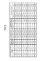
- FIG. 5 is a diagram illustrating the results of calculation for obtaining a short-pitch winding factor Kp, a distributed winding factor Kd, and a winding factor Kw, using tip widths ⁇ 1 and ⁇ 2 of the teeth of each phase as parameters.
- FIG. 6 is a diagram illustrating the winding factor ratio and the induced voltage ratio with reference to a case where the tip width ⁇ 1 of the central tooth of each phase is 40°.
- FIG. 1 is a transverse cross-sectional view of a synchronous motor according to an embodiment. As illustrated in FIG. 1 , in the present embodiment, an explanation will be given of an example of a synchronous motor that uses a rotor 4 , in which permanent magnets are positioned to face the inner periphery of a stator 1 .
- stator 1 nine projecting iron cores (hereinafter, “teeth”) 2 a , 2 b , and 2 c are formed on the annular iron core centering on the shaft center at equiangular intervals (a mechanical angle of 40°) in the circumferential direction, extending toward the shaft center.
- the teeth 2 a , 2 b , and 2 c are grouped into three phases (a U phase, a V phase, a W phase), with each phase including three adjacent teeth.
- the width of the portion of each of the teeth 2 a , 2 b , and 2 c facing the rotor 4 is hereinafter referred to as a “tip width”.
- permanent magnets 6 having 10-poles are provided on the outer periphery of a columnar back yoke 5 centering on the shaft center, at equiangular intervals (a mechanical angle of 36°) in the circumferential direction, with magnetic poles with different polarities being alternately provided.
- the rotor 4 is provided rotatably on the inner side of the teeth 2 a , 2 b , and 2 c such that it faces the stator 1 .
- FIG. 2 is a diagram illustrating a positional relation between teeth for one phase and magnetic poles of the synchronous motor according to the embodiment.
- Stator windings 3 of each of the phases are wound continuously in a concentrated manner around the respective teeth 2 a , 2 b , and 2 c for one phase, with the winding directions of the stator windings 3 wound around the adjacent teeth of each phase being opposite to each other as viewed from the shaft center.
- the tip width of the tooth 2 a positioned at the center for each phase is ⁇ 1 and the tip width of the teeth 2 b and 2 c positioned at both ends of each phase is ⁇ 2 .
- FIG. 3 is a diagram illustrating an example in which the center of a tooth and the center of a magnetic pole match each other.
- FIG. 4 is a diagram illustrating the induced voltages of the stator windings wound around the teeth for one phase.
- winding factor Kw As an index indicating how effectively the magnetic flux generated by permanent magnets of a rotor interlinks stator windings, there is a factor generally referred to as a “winding factor Kw”.
- the winding factor Kw is a product of a short-pitch winding factor Kp and a distributed winding factor Kd.
- the short-pitch winding factor Kp is calculated on the basis of the width of a magnetic pole of a rotor and the tip width of a tooth of a stator.
- the short-pitch winding factor Kp is a factor that indicates how much magnetic flux passes through the teeth around which stator windings are wound, assuming that the magnetic flux is generated sinusoidally from one magnetic pole of the rotor.
- the short-pitch winding factor Kp is calculated on the basis of the width (an angle) of one magnetic pole of the rotor and the tip width (an angle) of a tooth by using the following equation (1).
- the short-pitch winding factor Kp becomes 1, which is the maximum value.
- the tip width of the tooth is large, a part of the magnetic flux passing through the tooth does not interlink the stator winding and passes through the tip portion of the tooth, and is shunted to an adjacent magnetic pole. Therefore, the short-pitch winding factor Kp decreases.
- the tip width of the tooth is smaller than the width of the magnetic pole, not all the magnetic flux generated from the magnetic pole can interlink the stator winding. Therefore, the short-pitch winding factor Kp decreases.
- the distributed winding factor Kd is used for correcting the state where the amplitude of the induced voltage does not simply become the sum of the induced voltages of the respective stator windings, and the distributed winding factor Kd is generally calculated by using the following equation (2).
- q (number of slots)/(number of poles)/3)
- the ratio between the number of poles and the number of slots is a combination such as 2:3 or 4:3, which is generally used in a synchronous motor, even if the number of poles and the number of slots are increased, in the positional relation between the stator windings and the magnetic poles of each phase, only the number of repetitions of the same arrangement increases and the phases of the induced voltages generated in the respective stator windings constituting each phase are not shifted from each other. Therefore, the distributed winding factor Kd becomes 1.
- the distributed winding factor Kd obtained according to the above equation (2) is a factor that is calculated while assuming a case where stator teeth are provided at regular intervals and the tip widths of all the teeth are the same. Therefore, if the teeth are not placed at regular intervals or there is a tooth having a different tip width, the winding factor Kw cannot be calculated by using the above equation (2).
- each magnetic pole of the rotor 4 moves from right to left, in the induced voltages respectively generated in the stator windings wound around the teeth 2 a , 2 b , and 2 c , as illustrated in FIG. 4 , each of the phases of the induced voltages generated in the windings wound around the teeth 2 b and 2 c at both ends of each phase is shifted by the electric angle of 40° with respect to the induced voltage generated in the stator winding 3 wound around the central tooth 2 a of each phase.
- the sum of the induced voltages generated in the stator windings 3 wound around the respective teeth 2 a , 2 b , and 2 c becomes smaller than the value obtained by multiplying the induced voltage generated in the central tooth 2 a by three because of the influence of the shift of the phases of the induced voltages generated in the stator windings 3 wound around the respective teeth 2 a , 2 b , and 2 c .
- the distributed winding factor Kd of each of the teeth 2 a , 2 b , and 2 c corresponding to the above equation (2) is assumed, as a factor indicating the influence of a decrease of the induced voltage for each phase due to the shift of the phases of the induced voltages generated in the stator windings 3 wound around the respective teeth 2 b and 2 c at both ends of each phase, with respect to the induced voltage generated in the stator winding 3 wound around the central tooth 2 a of each phase, the distributed winding factor Kd can be calculated by using the following equation (3).
- Kd cos( ⁇ d/ 180°) (3)
- ⁇ d denotes a phase difference between the phases of the induced voltages generated in the stator windings 3 wound around the teeth 2 b and 2 c at both ends of each phase and the phase of the induced voltage generated in the stator winding 3 wound around the central tooth 2 a of each phase.
- the winding factor Kw of the 10-pole 9-slot synchronous motor according to the embodiment is obtained as described below.
- a winding factor Kw 1 of the stator winding 3 wound around the central tooth 2 a of each phase is as described below according to the equation (1) and the equation (3), where it is assumed that the short-pitch winding factor is Kp 1 and the distributed winding factor is Kd 1 .
- a winding factor Kw 2 of the stator windings 3 wound around the respective teeth 2 b and 2 c at both ends of each phase is as described below according to the equation (1) and the equation (3), where it is assumed that the short-pitch winding factor is Kp 2 and the distributed winding factor is Kd 2 .
- the winding factor Kw for each phase can be obtained according to the following equation (4).
- FIG. 5 is a diagram illustrating the results of calculation for obtaining the short-pitch winding factor Kp, the distributed winding factor Kd, and the winding factor Kw, using the tip widths ⁇ 1 and ⁇ 2 of the teeth of each phase as parameters.
- FIG. 6 is a diagram illustrating the winding factor ratio and the induced voltage ratio with reference to a case where the tip width ⁇ 1 of the central tooth of each phase is 40°.
- the solid line illustrated in FIG. 6 indicates the winding factor ratio with reference to the winding factor Kw when the winding factor Kw is obtained by using the above equation (4) and the tip width ⁇ 1 of the central tooth of each phase is 40°.
- the calculation result of the winding factor Kw in this case becomes 0.9452 as illustrated in FIG. 5 .
- the winding factor Kw gradually increases as the tip width ⁇ 1 of the central tooth of each phase decreases from 40° and becomes the largest when the tip width ⁇ 1 of the central tooth of each phase is 36° ( ⁇ 2 is 42°), which is 0.9553 as illustrated in FIG. 5 .
- the winding factor Kw gradually decreases as the tip width ⁇ 1 of the central tooth of each phase decreases from the tip width ⁇ 1 (36°) of the central tooth of each phase with which the winding factor Kw becomes the largest.
- the winding factor Kw becomes equal to the calculation result of the winding factor Kw obtained when the tip widths ⁇ 1 and ⁇ 2 of the teeth of each phase are equal to each other, i.e., 40°, which is 0.9452 as illustrated in FIG. 5 .
- the winding factor Kw becomes larger than that of the general 10-pole 9-slot synchronous motor in which the teeth are provided at equiangular intervals and the tip widths ⁇ 1 and ⁇ 2 of the teeth of each phase are equal to each other.
- the winding factor ratio obtained according to the above equation (4) approximately matches the induced voltage ratio obtained by the magnetic field analysis, as illustrated in FIG. 6 .
- the tip width ⁇ 1 of the central tooth of each phase is 36°, the induced voltage increases by up to about 1%.
- the synchronous motor is configured such that the tip width ⁇ 1 of the central tooth 2 a of each phase among the teeth 2 a , 2 b , and 2 c of each phase satisfies 32° ⁇ 1 ⁇ 40°. Accordingly, an induced voltage larger than that of the general 10-pole 9-slot synchronous motor can be acquired. Therefore, when a current equivalent to that of the general 10-pole 9-slot synchronous motor is carried, higher torque can be acquired and thus high output can be achieved.
- torque equivalent to that of the general 10-pole 9-slot synchronous motor can be acquired by carrying a current less than that of the general 10-pole 9-slot synchronous motor; therefore, high efficiency can be achieved.
- the tip width ⁇ 1 of the central tooth 2 a of each phase among the teeth 2 a , 2 b , and 2 c of each phase is approximately 36°, it is possible to acquire an induced voltage larger than that of the general 10-pole 9-slot synchronous motor by up to about 1%. Consequently, higher output and higher efficiency can be achieved.
- the winding factor Kw 1 of the stator winding wound around the central tooth of each phase indicates a higher value than the winding factor Kw 2 of the stator windings wound around the teeth at both ends of each phase. If the widths of the portions of the respective teeth around which the stator windings are wound are made non-uniform in accordance with the tip widths of the respective teeth and if the portions of the teeth at both ends of each phase around which the stator windings are wound are brought closer to the central tooth of each phase, the sectional area of the slot between the central tooth of each phase and the teeth at both ends of each phase decreases and the amount of the stator winding that can be accommodated in the slot decreases.
- the performance of the synchronous motor cannot be sufficiently achieved. Further, even if the sectional area of the slot between the respective phases increases, only a space that does not accommodate therein the winding increases, and the sectional area of the stator 1 cannot be effectively utilized. In addition, if the number of windings of the stator winding wound around the central tooth of each phase having a high winding factor Kw 1 is reduced, a decrease of the induced voltage increases, which is not effective.
- the teeth 2 a , 2 b , and 2 c are provided at equiangular intervals and the tip widths of the teeth 2 b and 2 c at both ends of each phase are set to be the same ⁇ 2 . Accordingly, harmonic components, which serve as distortions included in the induced voltages generated in the stator windings wound around the respective teeth, cancel out each other, and as a result, low distortion of the induced voltage can be achieved.
- the synchronous motor of the embodiment in the 10-pole 9-slot synchronous motor, by configuring the synchronous motor such that the tip width ⁇ 1 of the central tooth of each phase among the teeth of each phase grouped into three phases, with each phase including three adjacent teeth, satisfies 32° ⁇ 1 ⁇ 40°, an induced voltage larger than that of the general 10-pole 9-slot synchronous motor can be acquired. Therefore, when a current equivalent to that of the general 10-pole 9-slot synchronous motor is carried, higher torque can be acquired and thus high output can be achieved.
- torque equivalent to that of the general 10-pole 9-slot synchronous motor can be acquired by carrying a current less than that of the general 10-pole 9-slot synchronous motor; therefore, high efficiency can be achieved.
- the tip width ⁇ 1 of the central tooth of each phase among the teeth of each phase is approximately 36°, it is possible to acquire an induced voltage larger than that of the general 10-pole 9-slot synchronous motor by up to about 1%. Consequently, higher output and higher efficiency can be achieved.
- the synchronous motor according to the present invention is useful as a three-phase synchronous motor using permanent magnets and is particularly suitable as a 10-pole 9-slot synchronous motor.
Landscapes
- Engineering & Computer Science (AREA)
- Power Engineering (AREA)
- Iron Core Of Rotating Electric Machines (AREA)
- Permanent Magnet Type Synchronous Machine (AREA)
Abstract
Description
Kd=sin(π/6)/(q×sin(π/6/q))
(q=(number of slots)/(number of poles)/3) (2)
When q is an irreducible fraction, the value of the numerator is used.
Kd=cos(π×θd/180°) (3)
Claims (4)
Applications Claiming Priority (1)
| Application Number | Priority Date | Filing Date | Title |
|---|---|---|---|
| PCT/JP2013/051421 WO2014115278A1 (en) | 2013-01-24 | 2013-01-24 | Synchronous electric motor |
Publications (2)
| Publication Number | Publication Date |
|---|---|
| US20160006301A1 US20160006301A1 (en) | 2016-01-07 |
| US9800099B2 true US9800099B2 (en) | 2017-10-24 |
Family
ID=51227094
Family Applications (1)
| Application Number | Title | Priority Date | Filing Date |
|---|---|---|---|
| US14/655,766 Expired - Fee Related US9800099B2 (en) | 2013-01-24 | 2013-01-24 | Synchronous motor |
Country Status (5)
| Country | Link |
|---|---|
| US (1) | US9800099B2 (en) |
| EP (1) | EP2950431B1 (en) |
| JP (1) | JP6049765B2 (en) |
| CN (1) | CN104885345B (en) |
| WO (1) | WO2014115278A1 (en) |
Families Citing this family (4)
| Publication number | Priority date | Publication date | Assignee | Title |
|---|---|---|---|---|
| WO2015104821A1 (en) * | 2014-01-09 | 2015-07-16 | 三菱電機株式会社 | Synchronous motor drive circuit, synchronous motor driven by same, fan using this synchronous motor, air conditioner using this fan, and synchronous motor driving method |
| US10056812B2 (en) * | 2014-08-01 | 2018-08-21 | Piaggio & C. S.P.A. | Permanent magnet electric motor and generator and hybrid motor comprising it in a scooter |
| JP6391828B2 (en) * | 2015-06-17 | 2018-09-19 | 三菱電機株式会社 | Stator core and permanent magnet synchronous motor |
| JP7406739B2 (en) * | 2019-10-25 | 2023-12-28 | 政行 梨木 | Motor and its control device |
Citations (15)
| Publication number | Priority date | Publication date | Assignee | Title |
|---|---|---|---|---|
| JPS62110468A (en) | 1985-11-08 | 1987-05-21 | Hitachi Ltd | Permanent magnet field type brushless motor |
| JPS63144749A (en) | 1986-12-05 | 1988-06-16 | Nippon Fueroo Furuideikusu Kk | Motor |
| JPH0284043A (en) | 1989-07-13 | 1990-03-26 | Nippon Ferrofluidics Kk | motor |
| JPH05207692A (en) | 1992-01-22 | 1993-08-13 | Nagano Nippon Densan Kk | Magnet fixing structure to the yoke of spindle motor |
| US5396134A (en) | 1992-01-22 | 1995-03-07 | Nagano Nidec Corporation | Spindle motor |
| JPH09172762A (en) | 1996-12-27 | 1997-06-30 | Hitachi Ltd | Permanent magnet field type brushless motor |
| JP2000253602A (en) | 1999-02-26 | 2000-09-14 | Mitsubishi Electric Corp | DC motor |
| JP2001245460A (en) | 2000-02-29 | 2001-09-07 | Fujitsu General Ltd | Permanent magnet motor |
| JP2004215483A (en) | 2002-05-29 | 2004-07-29 | Matsushita Electric Ind Co Ltd | Motor generator |
| US20040245881A1 (en) | 2002-03-29 | 2004-12-09 | Naoyuki Kadoya | Motor |
| US20040251763A1 (en) | 2003-06-13 | 2004-12-16 | Matsushita Electric Industrial Co., Ltd. | Motor |
| US20050029890A1 (en) | 2002-05-29 | 2005-02-10 | Naoyuki Kadoya | Motor generator |
| JP2005102475A (en) | 2003-06-13 | 2005-04-14 | Matsushita Electric Ind Co Ltd | motor |
| JP2006191789A (en) | 2004-12-10 | 2006-07-20 | Nippon Densan Corp | Motor |
| JP2007259541A (en) | 2006-03-22 | 2007-10-04 | Mitsubishi Electric Corp | Permanent magnet motor |
-
2013
- 2013-01-24 EP EP13872806.8A patent/EP2950431B1/en not_active Not-in-force
- 2013-01-24 JP JP2014558363A patent/JP6049765B2/en not_active Expired - Fee Related
- 2013-01-24 CN CN201380068813.8A patent/CN104885345B/en not_active Expired - Fee Related
- 2013-01-24 WO PCT/JP2013/051421 patent/WO2014115278A1/en not_active Ceased
- 2013-01-24 US US14/655,766 patent/US9800099B2/en not_active Expired - Fee Related
Patent Citations (19)
| Publication number | Priority date | Publication date | Assignee | Title |
|---|---|---|---|---|
| JPS62110468A (en) | 1985-11-08 | 1987-05-21 | Hitachi Ltd | Permanent magnet field type brushless motor |
| JPS63144749A (en) | 1986-12-05 | 1988-06-16 | Nippon Fueroo Furuideikusu Kk | Motor |
| JPH0284043A (en) | 1989-07-13 | 1990-03-26 | Nippon Ferrofluidics Kk | motor |
| JPH05207692A (en) | 1992-01-22 | 1993-08-13 | Nagano Nippon Densan Kk | Magnet fixing structure to the yoke of spindle motor |
| US5396134A (en) | 1992-01-22 | 1995-03-07 | Nagano Nidec Corporation | Spindle motor |
| US5536986A (en) | 1992-01-22 | 1996-07-16 | Nagano Nidec Corporation | Spindle motor |
| US5698915A (en) | 1992-01-22 | 1997-12-16 | Nidec Corporation | Spindle motor |
| JPH09172762A (en) | 1996-12-27 | 1997-06-30 | Hitachi Ltd | Permanent magnet field type brushless motor |
| JP2000253602A (en) | 1999-02-26 | 2000-09-14 | Mitsubishi Electric Corp | DC motor |
| JP2001245460A (en) | 2000-02-29 | 2001-09-07 | Fujitsu General Ltd | Permanent magnet motor |
| US20040245881A1 (en) | 2002-03-29 | 2004-12-09 | Naoyuki Kadoya | Motor |
| JP2004215483A (en) | 2002-05-29 | 2004-07-29 | Matsushita Electric Ind Co Ltd | Motor generator |
| US20050029890A1 (en) | 2002-05-29 | 2005-02-10 | Naoyuki Kadoya | Motor generator |
| US20040251763A1 (en) | 2003-06-13 | 2004-12-16 | Matsushita Electric Industrial Co., Ltd. | Motor |
| CN1574546A (en) | 2003-06-13 | 2005-02-02 | 松下电器产业株式会社 | Motor |
| JP2005102475A (en) | 2003-06-13 | 2005-04-14 | Matsushita Electric Ind Co Ltd | motor |
| JP2006191789A (en) | 2004-12-10 | 2006-07-20 | Nippon Densan Corp | Motor |
| US20060197399A1 (en) | 2004-12-10 | 2006-09-07 | Nidec Corporation | Motor |
| JP2007259541A (en) | 2006-03-22 | 2007-10-04 | Mitsubishi Electric Corp | Permanent magnet motor |
Non-Patent Citations (5)
| Title |
|---|
| Ahmad, Mohd Saufi et al., "Permanent Magnet Brushless Machines with Minimum Difference in Slot Number and Pole Number", 2nd IEEE International Conference on Power and Energy, Dec. 1-3, 2008, Johor Baharu, Malaysia. |
| Extended European Search Report dated Nov. 10, 2016 issued in corresponding EP patent application No. 13872806.8. |
| International Search Report of the International Searching Authority dated Apr. 2, 2013 for the corresponding international application No. PCT/JP2013/051421 (and English translation). |
| Office Action dated Mar. 15, 2016 issued in corresponding JP patent application No. 2014-558363 (and partial English translation). |
| Office Action dated Nov. 2, 2016 issued in corresponding CN patent application No. 201380068813.8 (and partia English translation). |
Also Published As
| Publication number | Publication date |
|---|---|
| EP2950431B1 (en) | 2018-09-12 |
| CN104885345A (en) | 2015-09-02 |
| EP2950431A1 (en) | 2015-12-02 |
| US20160006301A1 (en) | 2016-01-07 |
| JP6049765B2 (en) | 2016-12-21 |
| CN104885345B (en) | 2017-08-22 |
| JPWO2014115278A1 (en) | 2017-01-19 |
| WO2014115278A1 (en) | 2014-07-31 |
| EP2950431A4 (en) | 2016-12-14 |
Similar Documents
| Publication | Publication Date | Title |
|---|---|---|
| US8421294B2 (en) | Rotary electric machine including auxiliary slot with center opposed to specified rotor portion | |
| US10199890B2 (en) | Embedded permanent magnet electric motor | |
| US20160172949A1 (en) | Synchronous motor | |
| JP6230927B2 (en) | motor | |
| US20060273684A1 (en) | Multi-phase brushless motor with reduced number of stator poles | |
| US20210218301A1 (en) | Rotating electric machine | |
| JP2012517209A (en) | Synchronous machine | |
| US10236732B2 (en) | Inductor type rotary motor | |
| US9800099B2 (en) | Synchronous motor | |
| WO2017171037A1 (en) | Rotor and method for designing rotor | |
| US10432040B2 (en) | Permanent magnet synchronous motor | |
| US10468921B2 (en) | Permanent magnet synchronous motor | |
| JP5907813B2 (en) | Brushless motor | |
| JP2009118594A (en) | Axial gap type motor | |
| JP6154637B2 (en) | Magnet generator | |
| JP5734135B2 (en) | Electric machine and manufacturing method thereof | |
| US10897165B2 (en) | Permanent magnet synchronous motor | |
| JP5668181B1 (en) | Magnet generator | |
| JP2010183655A (en) | Rotating electrical machine | |
| JP5611094B2 (en) | Rotating electric machine | |
| JP6100538B2 (en) | motor | |
| JP2017169257A (en) | Synchronous motor and synchronous generator | |
| JP2016019389A (en) | Rotary electric machine | |
| JP7534995B2 (en) | Rotating Electric Machine | |
| KR102622640B1 (en) | Magnetic device of double spoke type rotor |
Legal Events
| Date | Code | Title | Description |
|---|---|---|---|
| AS | Assignment |
Owner name: MITSUBISHI ELECTRIC CORPORATION, JAPAN Free format text: ASSIGNMENT OF ASSIGNORS INTEREST;ASSIGNORS:MATSUOKA, ATSUSHI;BABA, KAZUHIKO;ASO, HIROKI;AND OTHERS;SIGNING DATES FROM 20150610 TO 20150611;REEL/FRAME:035911/0783 |
|
| STCF | Information on status: patent grant |
Free format text: PATENTED CASE |
|
| MAFP | Maintenance fee payment |
Free format text: PAYMENT OF MAINTENANCE FEE, 4TH YEAR, LARGE ENTITY (ORIGINAL EVENT CODE: M1551); ENTITY STATUS OF PATENT OWNER: LARGE ENTITY Year of fee payment: 4 |
|
| FEPP | Fee payment procedure |
Free format text: MAINTENANCE FEE REMINDER MAILED (ORIGINAL EVENT CODE: REM.); ENTITY STATUS OF PATENT OWNER: LARGE ENTITY |
|
| LAPS | Lapse for failure to pay maintenance fees |
Free format text: PATENT EXPIRED FOR FAILURE TO PAY MAINTENANCE FEES (ORIGINAL EVENT CODE: EXP.); ENTITY STATUS OF PATENT OWNER: LARGE ENTITY |
|
| STCH | Information on status: patent discontinuation |
Free format text: PATENT EXPIRED DUE TO NONPAYMENT OF MAINTENANCE FEES UNDER 37 CFR 1.362 |
|
| FP | Lapsed due to failure to pay maintenance fee |
Effective date: 20251024 |