US9746223B2 - Air-conditioning apparatus - Google Patents
Air-conditioning apparatus Download PDFInfo
- Publication number
- US9746223B2 US9746223B2 US13/818,149 US201013818149A US9746223B2 US 9746223 B2 US9746223 B2 US 9746223B2 US 201013818149 A US201013818149 A US 201013818149A US 9746223 B2 US9746223 B2 US 9746223B2
- Authority
- US
- United States
- Prior art keywords
- refrigerant
- heat medium
- temperature
- pressure
- heat
- Prior art date
- Legal status (The legal status is an assumption and is not a legal conclusion. Google has not performed a legal analysis and makes no representation as to the accuracy of the status listed.)
- Active
Links
Images


Classifications
-
- F—MECHANICAL ENGINEERING; LIGHTING; HEATING; WEAPONS; BLASTING
- F25—REFRIGERATION OR COOLING; COMBINED HEATING AND REFRIGERATION SYSTEMS; HEAT PUMP SYSTEMS; MANUFACTURE OR STORAGE OF ICE; LIQUEFACTION SOLIDIFICATION OF GASES
- F25B—REFRIGERATION MACHINES, PLANTS OR SYSTEMS; COMBINED HEATING AND REFRIGERATION SYSTEMS; HEAT PUMP SYSTEMS
- F25B49/00—Arrangement or mounting of control or safety devices
- F25B49/02—Arrangement or mounting of control or safety devices for compression type machines, plants or systems
-
- F—MECHANICAL ENGINEERING; LIGHTING; HEATING; WEAPONS; BLASTING
- F25—REFRIGERATION OR COOLING; COMBINED HEATING AND REFRIGERATION SYSTEMS; HEAT PUMP SYSTEMS; MANUFACTURE OR STORAGE OF ICE; LIQUEFACTION SOLIDIFICATION OF GASES
- F25B—REFRIGERATION MACHINES, PLANTS OR SYSTEMS; COMBINED HEATING AND REFRIGERATION SYSTEMS; HEAT PUMP SYSTEMS
- F25B13/00—Compression machines, plants or systems, with reversible cycle
-
- F—MECHANICAL ENGINEERING; LIGHTING; HEATING; WEAPONS; BLASTING
- F25—REFRIGERATION OR COOLING; COMBINED HEATING AND REFRIGERATION SYSTEMS; HEAT PUMP SYSTEMS; MANUFACTURE OR STORAGE OF ICE; LIQUEFACTION SOLIDIFICATION OF GASES
- F25B—REFRIGERATION MACHINES, PLANTS OR SYSTEMS; COMBINED HEATING AND REFRIGERATION SYSTEMS; HEAT PUMP SYSTEMS
- F25B9/00—Compression machines, plants or systems, in which the refrigerant is air or other gas of low boiling point
- F25B9/002—Compression machines, plants or systems, in which the refrigerant is air or other gas of low boiling point characterised by the refrigerant
- F25B9/006—Compression machines, plants or systems, in which the refrigerant is air or other gas of low boiling point characterised by the refrigerant the refrigerant containing more than one component
-
- F—MECHANICAL ENGINEERING; LIGHTING; HEATING; WEAPONS; BLASTING
- F25—REFRIGERATION OR COOLING; COMBINED HEATING AND REFRIGERATION SYSTEMS; HEAT PUMP SYSTEMS; MANUFACTURE OR STORAGE OF ICE; LIQUEFACTION SOLIDIFICATION OF GASES
- F25B—REFRIGERATION MACHINES, PLANTS OR SYSTEMS; COMBINED HEATING AND REFRIGERATION SYSTEMS; HEAT PUMP SYSTEMS
- F25B2313/00—Compression machines, plants or systems with reversible cycle not otherwise provided for
- F25B2313/023—Compression machines, plants or systems with reversible cycle not otherwise provided for using multiple indoor units
- F25B2313/0231—Compression machines, plants or systems with reversible cycle not otherwise provided for using multiple indoor units with simultaneous cooling and heating
-
- F—MECHANICAL ENGINEERING; LIGHTING; HEATING; WEAPONS; BLASTING
- F25—REFRIGERATION OR COOLING; COMBINED HEATING AND REFRIGERATION SYSTEMS; HEAT PUMP SYSTEMS; MANUFACTURE OR STORAGE OF ICE; LIQUEFACTION SOLIDIFICATION OF GASES
- F25B—REFRIGERATION MACHINES, PLANTS OR SYSTEMS; COMBINED HEATING AND REFRIGERATION SYSTEMS; HEAT PUMP SYSTEMS
- F25B2313/00—Compression machines, plants or systems with reversible cycle not otherwise provided for
- F25B2313/027—Compression machines, plants or systems with reversible cycle not otherwise provided for characterised by the reversing means
- F25B2313/02732—Compression machines, plants or systems with reversible cycle not otherwise provided for characterised by the reversing means using two three-way valves
-
- F—MECHANICAL ENGINEERING; LIGHTING; HEATING; WEAPONS; BLASTING
- F25—REFRIGERATION OR COOLING; COMBINED HEATING AND REFRIGERATION SYSTEMS; HEAT PUMP SYSTEMS; MANUFACTURE OR STORAGE OF ICE; LIQUEFACTION SOLIDIFICATION OF GASES
- F25B—REFRIGERATION MACHINES, PLANTS OR SYSTEMS; COMBINED HEATING AND REFRIGERATION SYSTEMS; HEAT PUMP SYSTEMS
- F25B2313/00—Compression machines, plants or systems with reversible cycle not otherwise provided for
- F25B2313/027—Compression machines, plants or systems with reversible cycle not otherwise provided for characterised by the reversing means
- F25B2313/02741—Compression machines, plants or systems with reversible cycle not otherwise provided for characterised by the reversing means using one four-way valve
-
- F—MECHANICAL ENGINEERING; LIGHTING; HEATING; WEAPONS; BLASTING
- F25—REFRIGERATION OR COOLING; COMBINED HEATING AND REFRIGERATION SYSTEMS; HEAT PUMP SYSTEMS; MANUFACTURE OR STORAGE OF ICE; LIQUEFACTION SOLIDIFICATION OF GASES
- F25B—REFRIGERATION MACHINES, PLANTS OR SYSTEMS; COMBINED HEATING AND REFRIGERATION SYSTEMS; HEAT PUMP SYSTEMS
- F25B2400/00—General features or devices for refrigeration machines, plants or systems, combined heating and refrigeration systems or heat-pump systems, i.e. not limited to a particular subgroup of F25B
- F25B2400/08—Refrigeration machines, plants and systems having means for detecting the concentration of a refrigerant
-
- F—MECHANICAL ENGINEERING; LIGHTING; HEATING; WEAPONS; BLASTING
- F25—REFRIGERATION OR COOLING; COMBINED HEATING AND REFRIGERATION SYSTEMS; HEAT PUMP SYSTEMS; MANUFACTURE OR STORAGE OF ICE; LIQUEFACTION SOLIDIFICATION OF GASES
- F25B—REFRIGERATION MACHINES, PLANTS OR SYSTEMS; COMBINED HEATING AND REFRIGERATION SYSTEMS; HEAT PUMP SYSTEMS
- F25B2400/00—General features or devices for refrigeration machines, plants or systems, combined heating and refrigeration systems or heat-pump systems, i.e. not limited to a particular subgroup of F25B
- F25B2400/12—Inflammable refrigerants
-
- F—MECHANICAL ENGINEERING; LIGHTING; HEATING; WEAPONS; BLASTING
- F25—REFRIGERATION OR COOLING; COMBINED HEATING AND REFRIGERATION SYSTEMS; HEAT PUMP SYSTEMS; MANUFACTURE OR STORAGE OF ICE; LIQUEFACTION SOLIDIFICATION OF GASES
- F25B—REFRIGERATION MACHINES, PLANTS OR SYSTEMS; COMBINED HEATING AND REFRIGERATION SYSTEMS; HEAT PUMP SYSTEMS
- F25B25/00—Machines, plants or systems, using a combination of modes of operation covered by two or more of the groups F25B1/00 - F25B23/00
- F25B25/005—Machines, plants or systems, using a combination of modes of operation covered by two or more of the groups F25B1/00 - F25B23/00 using primary and secondary systems
Definitions
- the present invention relates to an air-conditioning apparatus applicable to, for example, multi-air-conditioning apparatuses for office buildings, and the like.
- a conventional air-conditioning apparatus such as a multi-air-conditioning apparatus for office buildings, performs a cooling operation or a heating operation by, for example, circulating a refrigerant between an outdoor unit, which is a heat source unit disposed outdoors, and indoor units disposed indoors. Specifically, conditioned spaces are cooled with the air that has been cooled by the refrigerant removing heat from the air and is heated with the air that has been heated by the refrigerant transferring its heat.
- HFC hydrofluorocarbon
- natural refrigerants such as carbon dioxide (CO2) are used.
- an air-conditioning apparatus having a different configuration represented by a chiller system.
- Such an air-conditioning apparatus performs cooling or heating as follows. Cooling energy or heating energy is generated in a heat source unit disposed outdoors. A heat medium such as water or antifreeze is heated or cooled by a heat exchanger disposed in the outdoor unit. The heat medium is conveyed to indoor units, such as fan coil units or panel heaters, disposed in space to be conditioned (see Patent Literature 1, for example).
- a heat source side heat exchanger called a heat recovery chiller that connects a heat source unit to each indoor unit with four water pipes arranged therebetween and supplies cooled and heated water or the like simultaneously so that cooling or heating can be freely selected in indoor units (see Patent Literature 2, for example).
- air-conditioning apparatuses such as a multi-air-conditioning apparatus for a building, include an air-conditioning apparatus in which a refrigerant is circulated from an outdoor unit to a relay unit and a heat medium, such as water, is circulated from the relay unit to each indoor unit to reduce conveyance power for the heat medium while circulating the heat medium, such as water, through the indoor unit (refer to Patent Literature 5, for example).
- the composition of the mixed refrigerant observed during the operation may become different from that observed at the time of injection of the mixed refrigerant because of different boiling points and so forth. Therefore, to control the operation with higher energy efficiency, it is necessary to grasp the composition during the circulation.
- the invention is to solve the above problems and to provide an air-conditioning apparatus that is environmentally friendly and save energy by grasping the composition of refrigerants in circulation on the basis of presumption or the like.
- An air-conditioning apparatus includes a refrigeration cycle device having a refrigerant circuit in which a compressor that sends out a zeotropic refrigerant mixture containing tetrafluoropropene and R32, a refrigerant flow switching device for switching a passage through which the refrigerant circulates, a heat source side heat exchanger for exchanging heat of the refrigerant, a refrigerant expansion device for controlling pressure of the refrigerant, and a heat exchanger related to heat medium that is capable of exchanging heat between the refrigerant and a heat medium different from the refrigerant are connected by pipes in order to circulate the refrigerant.
- the refrigeration cycle device includes a circulating refrigerant composition detection circuit having a low-pressure side pressure detection device for detecting low-pressure side pressure corresponding to pressure of the refrigerant suctioned by the compressor, a high-low pressure bypass pipe connecting a pipe on a discharge side of the compressor and a pipe on a suction side of the compressor, a bypass expansion device disposed in the high-low pressure bypass pipe, a high-pressure side temperature detection device for detecting high-pressure side temperature corresponding to temperature of the refrigerant flowing into the bypass expansion device, a low-pressure side temperature detection device for detecting low-pressure side temperature corresponding to temperature of the refrigerant discharged from the bypass expansion device, and a heat exchanger related to refrigerant that exchanges heat between the refrigerant flowing into the bypass expansion device and the refrigerant discharged from the bypass expansion device.
- This apparatus also includes a heat medium side device having a heat medium circulation circuit in which a heat medium sending device for circulating the heat medium for the heat exchange performed by the heat exchanger related to heat medium, a use side heat exchanger that exchanges heat between the heat medium and air in a space to be conditioned, and a heat medium flow switching device that switches a passage of the heat medium having flowed through the heat exchanger related to heat medium to the use side heat exchanger are connected by pipes.
- the apparatus further includes a first controller that detects the composition of circulating refrigerant in the refrigeration cycle device on the basis of at least the low-pressure side pressure, the high-pressure side temperature, and the low-pressure side temperature.
- the apparatus also includes a second controller disposed at a position away from the first controller and connecting to be capable of communicating to the first controller with wire or no wire.
- the second controller performs, in a heat medium relay unit including the heat exchanger related to heat medium, at least one of a calculation of evaporating temperature of the heat exchanger related to heat medium that functions as an evaporator and degree of superheat on a refrigerant outlet side thereof and a calculation of condensing temperature of the heat exchanger related to heat medium that functions as a condenser and degree of subcooling on the refrigerant outlet side thereof, on the basis of the circulation composition received through the communication with the first controller.
- At least the compressor, the refrigerant flow switching device, the heat source side heat exchanger, and the circulating refrigerant composition detection circuit are accommodated in an outdoor unit, and at least the heat exchanger related to heat medium and the refrigerant expansion device are accommodated in the heat medium relay unit.
- the outdoor unit and the heat medium relay unit are provided separately and are installable at separate positions to be away from each other.
- the first controller is disposed in or near the outdoor unit.
- the second controller is disposed in or near the heat medium relay unit.
- the composition of a refrigerant containing a plurality of components and circulating during the operation is detected on the basis of the pressures and the temperatures on the discharge side and the suction side of the compressor. Therefore, the evaporating temperature, the degree of superheat, the condensing temperature, and the degree of subcooling for the heat exchanger related to heat medium can be determined in accordance with the composition, whereby the refrigerant expansion device can be controlled.
- an air-conditioning apparatus having high energy efficiency is provided, and energy can be saved. Since the pipes through which the medium circulates can be made shorter than that of other air-conditioning apparatuses such as a chiller, conveyance power can be reduced and energy can be further saved.
- the heat medium circulates through the indoor unit, even if, for example, the refrigerant leaks into the conditioned space, entry of the refrigerant into the room can be suppressed.
- a safe air-conditioning apparatus is provided.
- FIG. 1 is a system configuration diagram of an air-conditioning apparatus according to Embodiment of the invention.
- FIG. 2 is another system configuration diagram of the air-conditioning apparatus of Embodiment according to the invention.
- FIG. 3 is a system circuit diagram of the air-conditioning apparatus according to Embodiment of the invention.
- FIG. 3A is another system circuit diagram of the air-conditioning apparatus according to Embodiment of the invention.
- FIG. 4 is an exemplary p-h diagram of the air-conditioning apparatus according to Embodiment.
- FIG. 5 is a diagram for describing circulation composition detection performed by the air-conditioning apparatus according to Embodiment.
- FIG. 6 is a diagram illustrating a flowchart for a process of circulation composition detection performed by the air-conditioning apparatus according to Embodiment.
- FIG. 7 is another exemplary p-h diagram of the air-conditioning apparatus according to Embodiment.
- FIG. 8 is a system circuit diagram of the air-conditioning apparatus according to Embodiment during cooling only operation.
- FIG. 9 is a system circuit diagram of the air-conditioning apparatus according to Embodiment during heating only operation.
- FIG. 10 is a system circuit diagram of the air-conditioning apparatus according to Embodiment during cooling main operation.
- FIG. 11 is a system circuit diagram of the air-conditioning apparatus according to Embodiment during heating main operation.
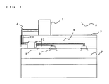
- FIGS. 1 and 2 are schematic diagrams illustrating exemplary installations of the air-conditioning apparatus according to Embodiment of the invention.
- the exemplary installations of the air-conditioning apparatus will be described with reference to FIGS. 1 and 2 .
- each indoor unit can freely select an operation mode from a cooling mode and a heating mode with the use of devices including instruments and the like forming circuits (a refrigerant circuit (refrigeration cycle) A and a heat medium circuit B) through which a heat source side refrigerant (hereinafter referred to as refrigerant) and a heat medium are made to circulate, respectively.
- refrigerant heat source side refrigerant
- the air-conditioning apparatus includes a single outdoor unit 1 , functioning as a heat source unit, a plurality of indoor units 2 , and a heat medium relay unit 3 disposed between the outdoor unit 1 and the indoor units 2 .
- the heat medium relay unit 3 exchanges heat between the heat source side refrigerant and the heat medium.
- the outdoor unit 1 and the heat medium relay unit 3 are connected with refrigerant pipes 4 through which the heat source side refrigerant flows.
- the heat medium relay unit 3 and each indoor unit 2 are connected with pipes 5 (heat medium pipes) through which the heat medium flows. Cooling energy or heating energy generated in the outdoor unit 1 is delivered through the heat medium relay unit 3 to the indoor units 2 .
- the air-conditioning apparatus includes the single outdoor unit 1 , the plurality of indoor units 2 , and a plurality of separated heat medium relay units 3 (a main heat medium relay unit 3 a and sub heat medium relay units 3 b ) arranged between the outdoor unit 1 and the indoor units 2 .
- the outdoor unit 1 and the main heat medium relay unit 3 a are connected with the refrigerant pipes 4 .
- the main heat medium relay unit 3 a and the sub heat medium relay units 3 b are connected with the refrigerant pipes 4 .
- Each of the sub heat medium relay units 3 b is connected to each indoor unit 2 by the pipes 5 . Cooling energy or heating energy generated in the outdoor unit 1 is delivered through the main heat medium relay unit 3 a and the sub heat medium relay units 3 b to the indoor units 2 .
- the outdoor unit 1 is typically disposed in an outdoor space 6 which is a space (e.g., a roof) outside of a structure 9 , such as an office building, and is configured to supply cooling energy or heating energy through the heat medium relay unit 3 to the indoor units 2 .
- Each indoor unit 2 is disposed at a position that can supply cooling air or heating air to an indoor space 7 , which is an indoor space (e.g., a living room) inside of the structure 9 , and supplies cooling air or heating air to the indoor space 7 as a space to be conditioned.
- the heat medium relay unit 3 is configured with a housing separate from the outdoor unit 1 and the indoor units 2 such that the heat medium relay unit 3 can be disposed at a position different from those of the outdoor space 6 and the indoor space 7 , that is, at an unconditioned space, and is connected to the outdoor unit 1 through the refrigerant pipes 4 and is connected to the indoor units 2 through the pipes 5 to convey cooling energy or heating energy, supplied from the outdoor unit 1 to the indoor units 2 .
- the outdoor unit 1 is connected to the heat medium relay unit 3 using two refrigerant pipes 4
- the heat medium relay unit 3 is connected to each indoor unit 2 using a pair of pipes 5 .
- each of the units (the outdoor unit 1 , the indoor units 2 , and the heat medium relay unit 3 ) is connected using two pipes (the refrigerant pipes 4 or the pipes 5 ), thus construction is facilitated.
- the heat medium relay unit 3 can be separated into a single main heat medium relay unit 3 a and two sub heat medium relay units 3 b (a sub heat medium relay unit 3 b ( 1 ) and a sub heat medium relay unit 3 b ( 2 )) branched off from the main heat medium relay unit 3 a .
- This separation allows the plurality of sub heat medium relay units 3 b to be connected to the single main heat medium relay unit 3 a .
- the main heat medium relay unit 3 a is connected to each sub heat medium relay unit 3 b by three refrigerant pipes 4 .
- Such a circuit will be described in detail later (refer to FIG. 3A ).
- FIGS. 1 and 2 illustrate a state where each heat medium relay unit 3 is disposed in the structure 9 but in a space different from the indoor space 7 , for example, an unconditioned space such as a space above a ceiling (hereinafter, simply referred to as a “space 8 ”).
- the heat medium relay unit 3 can be disposed in other spaces, such as a common space where an elevator or the like is installed.
- FIGS. 1 and 2 illustrate a case where the indoor units 2 are of a ceiling cassette type, the indoor units are not limited to this type and may be of any type, such as a ceiling concealed type or a ceiling suspended type, as long as the indoor units 2 are capable of blowing out heating air or cooling air into the indoor space 7 directly or through a duct or the like.
- FIGS. 1 and 2 illustrate the case in which the outdoor unit 1 is disposed in the outdoor space 6
- the arrangement is not limited to this case.
- the outdoor unit 1 may be disposed in an enclosed space, for example, a machine room with a ventilation opening, may be disposed inside of the structure 9 as long as waste heat can be exhausted through an exhaust duct to the outside of the structure 9 , or may be disposed inside of the structure 9 in the use of the outdoor unit 1 of a water-cooled type. There is no particular problem when the outdoor unit 1 is disposed in such a place.
- the heat medium relay unit 3 can be disposed near the outdoor unit 1 . If the distance between the heat medium relay unit 3 and each indoor unit 2 is too long, the conveyance power for the heat medium becomes considerably large. It should be therefore noted that the energy saving effect is reduced in this case. Additionally, the numbers of connected outdoor units 1 , indoor units 2 , and heat medium relay units 3 are not limited to those illustrated in FIGS. 1 and 2 . The numbers thereof can be determined in accordance with the structure 9 where the air-conditioning apparatus according to Embodiment is installed.
- FIG. 3 is a schematic configuration diagram illustrating an exemplary circuit configuration of the air-conditioning apparatus (hereinafter, referred to as an “air-conditioning apparatus 100 ”) according to Embodiment.
- the detailed configuration of the air-conditioning apparatus 100 will be described with reference to FIG. 3 .
- the outdoor unit 1 and the heat medium relay unit 3 are connected with the refrigerant pipes 4 through heat exchangers 15 a and 15 b related to heat medium included in the heat medium relay unit 3 .
- the heat medium relay unit 3 and the indoor units 2 are connected with the pipes 5 (a pipe 5 a to a pipe 5 d ) through the heat exchangers 15 a and 15 b related to heat medium.
- the refrigerant pipes 4 will be described in detail later.
- the outdoor unit 1 includes a compressor 10 , a first refrigerant flow switching device 11 , such as a four-way valve, a heat source side heat exchanger 12 , and an accumulator 19 , which are connected in series by the refrigerant pipes 4 .
- the outdoor unit 1 further includes a first connecting pipe 4 a , a second connecting pipe 4 b , a check valve 13 a , a check valve 13 b , a check valve 13 c , and a check valve 13 d .
- Such an arrangement of the first connecting pipe 4 a , the second connecting pipe 4 b , the check valve 13 a , the check valve 13 b , the check valve 13 c , and the check valve 13 d enables the heat source side refrigerant, allowed to flow into the heat medium relay unit 3 , to flow in a constant direction irrespective of an operation requested by any indoor unit 2 .
- An outdoor unit side controller 50 corresponding to a first controller, controls devices included in the outdoor unit 1 .
- the outdoor unit side controller 50 controls the driving frequency of the compressor 10 , the switching of the first refrigerant flow switching device 11 , the rotation speed (including ON/OFF) of an air-sending device (not illustrated) that sends air toward the heat source side heat exchanger 12 , and so forth.
- the outdoor unit side controller 50 also controls operations and the like concerning the entirety of the air-conditioning apparatus 100 in cooperation with a relay unit side controller 60 corresponding to a second controller, and so forth by transmitting and receiving signals through wired, radio, or any other type of communication.
- the outdoor unit side controller 50 performs a detection process in which the composition of the refrigerant circulating through the refrigerant circuit A is presumed and detected.
- the outdoor unit 1 further includes a high-low pressure bypass pipe 4 c that connects passages on the discharge side and the suction side of the compressor 10 , thereby forming a circulation composition detection circuit.
- a bypass expansion device 14 disposed in the high-low pressure bypass pipe 4 c controls the flow rate and the pressure of the refrigerant flowing through the high-low pressure bypass pipe 4 c .
- the bypass expansion device 14 may be an electronic expansion valve capable of changing its opening degree, or a capillary tube or the like whose amount of expansion is fixed.
- a heat exchanger 20 related to refrigerant exchanges heat between refrigerants obtained before and after the passage through the bypass expansion device 14 .
- the heat exchanger 20 related to refrigerant according to Embodiment is, for example, a double-pipe heat exchanger but is not limited thereto.
- the heat exchanger 20 related to refrigerant may alternatively be a plate heat exchanger, a microchannel heat exchanger, or the like that is capable of exchanging heat between a refrigerant on the high-pressure side and a refrigerant on the low-pressure side.
- a high-pressure side refrigerant temperature detection device 32 and a low-pressure side refrigerant temperature detection device 33 are temperature sensors of, for example, a thermistor type or the like.
- the high-pressure side refrigerant temperature detection device 32 is disposed on the inlet side (refrigerant inlet side) of the bypass expansion device 14 and detects a refrigerant temperature TH on the high-pressure side of the refrigerant circuit A.
- the low-pressure side refrigerant temperature detection device 33 is disposed on the outlet side (refrigerant outlet side) of the bypass expansion device 14 and detects a refrigerant temperature TL on the low-pressure side of the refrigerant circuit A.
- a high-pressure side pressure detection device 37 and a low-pressure side pressure detection device 38 are pressure sensors of, for example, a strain-gauge type, a semiconductor type, or the like.
- the high-pressure side pressure detection device 37 detects pressure PH on the high-pressure side (pressure on the discharge side) of the compressor 1 (refrigerant circuit A).
- the low-pressure side pressure detection device 38 detects pressure PL on the low-pressure side (pressure on the suction side) of the compressor 1 .
- the low-pressure side pressure detection device 38 is provided in a passage disposed between the accumulator 19 and the first refrigerant flow switching device 11 , but the position thereof is not limited thereto.
- the low-pressure side pressure detection device 38 may be provided at any position such as a position in a passage disposed between the compressor 10 and the accumulator 19 , as long as the low-pressure side pressure detection device 38 can detect the pressure on the low-pressure side of the compressor 10 .
- the high-pressure side pressure detection device 37 may also be provided at any position, as long as the high-pressure side pressure detection device 37 can measure the pressure on the high-pressure side of the compressor 10 .
- the compressor 10 is configured to suction the heat source side refrigerant and compress the heat source side refrigerant to a high-temperature, high-pressure state, and may be a capacity-controllable inverter compressor, for example.
- the first refrigerant flow switching device 11 switches the flow of the heat source side refrigerant between a heating operation (a heating only operation mode and a heating main operation mode) and a cooling operation (a cooling only operation mode and a cooling main operation mode).
- the heat source side heat exchanger 12 functions as an evaporator in the heating operation, functions as a condenser (or a radiator) in the cooling operation, exchanges heat between air supplied from the air-sending device, such as a fan (not illustrated), and the heat source side refrigerant, and evaporates and gasifies or condenses and liquefies the heat source side refrigerant.
- the accumulator 19 is provided on the suction side of the compressor 10 and retains excess refrigerant.
- the check valve 13 d is disposed in the refrigerant pipe 4 positioned between the heat medium relay unit 3 and the first refrigerant flow switching device 11 and is configured to permit the heat source side refrigerant to flow only in a predetermined direction (the direction from the heat medium relay unit 3 to the outdoor unit 1 ).
- the check valve 13 a is disposed in the refrigerant pipe 4 positioned between the heat source side heat exchanger 12 and the heat medium relay unit 3 and is configured to permit the heat source side refrigerant to flow only in a predetermined direction (the direction from the outdoor unit 1 to the heat medium relay unit 3 ).
- the check valve 13 b is disposed in the first connecting pipe 4 a and is configured to allow the heat source side refrigerant, discharged from the compressor 10 in the heating operation, to flow to the heat medium relay unit 3 .
- the check valve 13 c is disposed in the second connecting pipe 4 b and is configured to allow the heat source side refrigerant, returned from the heat medium relay unit 3 in the heating operation, to flow to the suction side of the compressor 10 .
- the first connecting pipe 4 a is configured to connect the refrigerant pipe 4 , positioned between the first refrigerant flow switching device 11 and the check valve 13 d , to the refrigerant pipe 4 , positioned between the check valve 13 a and the heat medium relay unit 3 , in the outdoor unit 1 .
- the second connecting pipe 4 b is configured to connect the refrigerant pipe 4 , positioned between the check valve 13 d and the heat medium relay unit 3 , to the refrigerant pipe 4 , positioned between the heat source side heat exchanger 12 and the check valve 13 a , in the outdoor unit 1 . It should be noted that FIG.
- FIG 3 illustrates a case in which the first connecting pipe 4 a , the second connecting pipe 4 b , the check valve 13 a , the check valve 13 b , the check valve 13 c , and the check valve 13 d are provided, but the devices is not limited to this case, and they may be omitted.
- a mixed refrigerant containing tetrafluoropropene such as HFO-1234yf or HFO-1234ze expressed by the chemical formula C3H2F4, and difluoromethane (R32) expressed by the chemical formula CH2F2 is injected into the refrigerant pipes, and the mixed refrigerant circulates through the refrigerant pipes.
- Tetrafluoropropene which has a double bond in its chemical formula, is easy to be decomposed in the atmosphere and has a low GWP (4 to 6). That is, tetrafluoropropene is, for example, an environmentally friendly refrigerant. However, tetrafluoropropene has lower density than a conventional refrigerant such as R410A. Therefore, to obtain a large heating capacity or a large cooling capacity by using tetrafluoropropene alone as the refrigerant, a very large compressor is required. Moreover, to prevent the increase in pressure loss that may occur in pipes, refrigerant pipes having large diameters are also required. Consequently, the air-conditioning apparatus costs high.
- R32 has characteristics similar to those of, for example, conventional refrigerants such as R410A. Therefore, fewer changes in the apparatus are required. That is, R32 is a refrigerant that is relatively easy to use. However, the GWP of R32 is 675, which is smaller than 2088 of R410A or the like but is considered to be relatively large from the environmental point of view.
- a mixed refrigerant containing tetrafluoropropene and R32 is used.
- Such a mixed refrigerant contributes to a reduction in GWP and improvements in refrigerant characteristics, whereby an earth-friendly, efficient air-conditioning apparatus is obtained.
- the mixing ratio of tetrafluoropropene to R32 is not limited to and may be, for example, 70 to 30 or the like in percentage by mass.
- FIG. 4 is a p-h diagram of the mixed refrigerant according to Embodiment 1.
- HFO-1234yf has a boiling point of ⁇ 29° C.
- R32 has a boiling point of ⁇ 53.2° C. That is, the mixed refrigerant is a zeotropic refrigerant mixture whose components have different dew points and different boiling points. Since, for example, there are liquid reservoirs such as the accumulator 19 in the refrigerant circuit A, the mixed refrigerant containing a plurality of components and circulating through the circuit exhibits a variable composition during the circulation (hereinafter referred to as circulation composition) that is not fixed by the mixing ratio.
- circulation composition a variable composition during the circulation
- the saturated liquid temperature and the saturated gas temperature are different at the same pressure.
- a saturated liquid temperature TL 1 and a saturated gas temperature TG 1 at a pressure P 1 are not equal, specifically; the saturated gas temperature TG 1 is higher than the saturated liquid temperature TL 1 . Therefore, isothermal lines in the two-phase region of the p-h diagram are tilted (have a gradient).
- the p-h diagram changes and the gradient of the isothermal lines also changes.
- the gradient angle is 5.0° C. on the high-pressure side and 7° C. on the low-pressure side, approximately.
- the gradient angle is 2.3° C. on the high-pressure side and 2.8° C. on the low-pressure side, approximately. Therefore, to accurately calculate the saturated liquid temperature and the saturated gas temperature at a pressure in the refrigerant circuit A, the circulation composition of the refrigerant in the refrigerant circuit A needs to be detected.
- the air-conditioning apparatus includes a circulation composition detection circuit in which the high-low pressure bypass pipe 4 c is provided with the bypass expansion device 14 and the heat exchanger 20 related to refrigerant.
- the circulation composition of the refrigerant in the refrigerant circuit A is detected on the basis of the temperatures detected by the high-pressure side refrigerant temperature detection device 32 and the low-pressure side refrigerant temperature detection device 33 and the pressures detected by the high-pressure side pressure detection device 37 and the low-pressure side pressure detection device 38 . That is, the circulation composition is detected by a refrigerant circuit as the circulation composition detection circuit not including devices such as the accumulator 19 and in which the passage from the compressor 10 is short. Thus, accurate detection can be performed.
- FIG. 5 is a vapor-liquid equilibrium diagram of a two-component mixed refrigerant at the pressure P 1 .
- the two solid lines illustrated in FIG. 5 represent a dew-point curve, which is a saturated gas line obtained when a gas refrigerant is condensed and liquefied, and a boiling-point curve, which is a saturated liquid line obtained when a liquid refrigerant is evaporated and gasified, respectively.
- FIG. 6 is a diagram illustrating a flowchart for a process of detecting circulation composition. Referring to FIG. 6 , a procedure will be described in accordance with which the outdoor unit side controller 50 detects the composition of the refrigerant that is circulating through the refrigerant circuit A. Herein, the detection of the circulation composition of a mixed refrigerant containing two components will be described.
- the outdoor unit side controller 50 starts the process (ST 1 ).
- the pressure (high-pressure side pressure) PH detected by the high-pressure side pressure detection device 37 , the temperature (high-pressure side temperature) TH detected by the high-pressure side refrigerant temperature detection device 32 , the pressure (low-pressure side pressure) PL detected by the low-pressure side pressure detection device 38 , and the temperature (low-pressure side temperature) TL detected by the low-pressure side refrigerant temperature detection device 33 are measured (ST 2 ).
- the circulation compositions of the two components contained in the mixed refrigerant that is circulating through the refrigerant circuit A are assumed to be ⁇ 1 and ⁇ 2, (ST 3 ).
- the initial values of ⁇ 1 and ⁇ 2 are not especially limited to and may be, for example, based on the mixing ratio obtained at the time of injection of the refrigerant, for example, 0.7 for ⁇ 1 and 0.3 for ⁇ 2.
- FIG. 7 is a p-h diagram illustrating the high-pressure side pressure PH, the high-pressure side temperature TH, the low-pressure side pressure PL, and the low-pressure side temperature TL.
- a quality X of the two-phase refrigerant on the outlet side of the bypass expansion device 14 is calculated from the low-pressure side pressure PL and the enthalpy hH and in accordance with Expression (1) given below (ST 5 ) (point B in FIG. 7 ).
- hb denotes the saturated liquid enthalpy at the low-pressure side pressure PL
- hd denotes the saturated gas enthalpy at the low-pressure side pressure PL.
- a temperature TL′ of the refrigerant at the quality X is calculated from a saturated gas temperature TLG and a saturated liquid temperature TLL at the low-pressure side pressure PL and in accordance with Expression (2) given below (ST 6 ).
- TL′ TLL ⁇ (1 ⁇ X )+ TLG ⁇ X (2)
- TL′ thus calculated is regarded as being equal to the detected temperature TL (ST 7 ). If not equal, the assumed circulation compositions ⁇ 1 and ⁇ 2 of the two components of the refrigerant are amended (ST 8 ) and the process is repeated from step ST 4 . If it is determined that TL′ and TL are regarded as being substantially equal, it is regarded that the circulation compositions have been identified and the process ends (ST 9 ). Through such a process, the circulation composition of a two-component zeotropic refrigerant mixture can be detected.
- the saturated liquid temperature and the saturated gas temperature observed when ⁇ 1 is 0.8 and ⁇ 2 is 0.2 are ⁇ 0.4° C. and 8.5° C., respectively.
- the saturated liquid temperature and the saturated gas temperature observed when ⁇ 1 is 0.7 and ⁇ 2 is 0.3 are ⁇ 3.3° C. and 3.6° C., respectively.
- the saturated liquid temperature and the saturated gas temperature observed when ⁇ 1 is 0.6 and ⁇ 2 is 0.4 are ⁇ 5.1° C. and ⁇ 0.5° C., respectively.
- the outdoor unit side controller 50 stores data on such relationships of ⁇ 1 and ⁇ 2 with respect to the saturated liquid temperature and the saturated gas temperature in the form of functions, tables, and the like in a storage device (not illustrated), and uses the data in performing the above process.
- the temperature TL′ calculated in accordance with Expression (2) is 6.7° C. when ⁇ 1 is 0.8 and ⁇ 2 is 0.2, 2.2° C. when ⁇ 1 is 0.7 and ⁇ 2 is 0.3, and ⁇ 1.4 when ⁇ 1 is 0.6 and ⁇ 2 is 0.4.
- the measured low-pressure side temperature TL is 0° C.
- ⁇ 1 is supposed to be between 0.7 and 0.6
- ⁇ 2 is supposed to be between 0.3 and 0.4. Therefore, ⁇ 1 is amended to be reduced while ⁇ 2 is amended to be increased. Then, the circulation composition of the mixed refrigerant with which the measured temperature TL and the calculated temperature TL′ match is obtained.
- a three-component mixed refrigerant containing, for example, another additional component is also acceptable.
- another additional component for example, even in a case of a three-component zeotropic refrigerant mixture, there is a correlation in terms of ratio between two of the components.
- the circulation composition of a pair of two components is assumed to be ⁇ 1
- the circulation composition of the remaining component can be assumed to be ⁇ 2. Therefore, the circulation composition of the three-component mixed refrigerant can be obtained through the substantially same process as that for the detection of the circulation composition of a two-component refrigerant.
- the circulation composition of a mixed refrigerant can be detected. Furthermore, if a certain pressure is detected, saturated liquid temperature and saturated gas temperature at that pressure can be arithmetically calculated. For example, if the mean temperature (simple average temperature) of the saturated liquid temperature and the saturated gas temperature is determined as the saturation temperature at that pressure, the saturation temperature can be used in, for example, controlling the compressor 10 and a refrigerant expansion device 16 . As another alternative, since the heat transfer coefficient of the refrigerant varies with the quality of the refrigerant, weighted mean temperature obtained by weighing the saturated liquid temperature and the saturated gas temperature may be taken as the saturation temperature. An operation of controlling the refrigerant expansion device 16 will be described separately below.
- the low-pressure side evaporation side
- the temperature of a two-phase refrigerant at the inlet of the evaporator is measured and the result is assumed to be the saturated liquid temperature or the temperature of the two-phase refrigerant at a preset quality
- factors such as pressure and saturated gas temperature can be obtained, even without measuring the pressure, by calculating backward in accordance with the relative expression for calculating saturated liquid temperature and saturated gas temperature from circulation composition and pressure. Therefore, the low-pressure side pressure detection device is not essential. Nevertheless, it is necessary to assume the point where the temperature has been measured as being the saturated liquid temperature or to set the quality. Therefore, saturated liquid temperature and saturated gas temperature can be obtained more accurately by using any pressure detection device.
- a mixed refrigerant having such characteristics that, on the high-pressure side (condensation side), isothermal lines in the subcooled-liquid zone extend substantially vertically and the temperature does not change with the pressure as illustrated in FIG. 7 .
- a mixed refrigerant containing HFO-1234yf (tetrafluoropropene) and R32 has the above characteristics.
- the enthalpy hH can be determined by liquid temperature alone even without the high-pressure side pressure detection device 37 . That is, the high-pressure side pressure detection device 37 is not an essential detection device.
- the indoor units 2 each include a use side heat exchanger 26 .
- Each of the use side heat exchangers 26 is connected by the pipes 5 to a heat medium flow control device 25 and a second heat medium flow switching device 23 arranged in the heat medium relay unit 3 .
- the use side heat exchanger 26 is configured to exchange heat between air supplied from an air-sending device, such as a fan (not illustrated), and the heat medium in order to generate heating air or cooling air to be supplied to the indoor space 7 .
- FIG. 4 illustrates a case in which four indoor units 2 are connected to the heat medium relay unit 3 . Illustrated are, from the bottom of the drawing, an indoor unit 2 a , an indoor unit 2 b , an indoor unit 2 c , and an indoor unit 2 d .
- the use side heat exchangers 26 are illustrated as a use side heat exchanger 26 a , a use side heat exchanger 26 b , a use side heat exchanger 26 c , and a use side heat exchanger 26 d in that order from the bottom of the drawing sheet so as to correspond to the indoor units 2 a to 2 d , respectively. Note that as is the case of FIGS. 1 and 2 , the number of connected indoor units 2 illustrated in FIG. 4 is not limited to four.
- the heat medium relay unit 3 includes the two heat exchangers 15 related to heat medium, two refrigerant expansion devices 16 , two opening and closing devices 17 , two second refrigerant flow switching devices 18 , two pumps 21 , four first heat medium flow switching devices 22 , the four second heat medium flow switching devices 23 , and the four heat medium flow control devices 25 .
- An air-conditioning apparatus in which the heat medium relay unit 3 is separated into the main heat medium relay unit 3 a and the sub heat medium relay unit 3 b will be described later with reference to FIG. 3A .
- the relay unit side controller 60 corresponding to the second controller, controls devices included in the heat medium relay unit 3 .
- the relay unit side controller 60 controls the opening degrees of the refrigerant expansion devices 16 , the opening and closing of the opening and closing devices 17 , the switching of the second refrigerant flow switching devices 18 , the first heat medium flow switching devices 22 , and the second heat medium flow switching devices 23 , and so forth in the refrigerant circuit A. Furthermore, the relay unit side controller 60 controls the driving of the pumps 21 , the opening degrees of the heat medium flow control devices 25 , and so forth in the heat medium circuit B.
- the relay unit side controller 60 calculates, for example, the evaporating temperatures, the degree of superheat, the condensing temperatures, and the degree of subcooling for the heat exchangers 15 related to heat medium, thereby controlling the opening degrees of the refrigerant expansion devices 16 and other operations.
- Each of the two heat exchangers 15 related to heat medium functions as a condenser (radiator) or an evaporator and exchanges heat between the heat source side refrigerant and the heat medium in order to transfer cooling energy or heating energy, generated in the outdoor unit 1 and stored in the heat source side refrigerant, to the heat medium.
- the heat exchanger 15 a related to heat medium is disposed between a refrigerant expansion device 16 a and a second refrigerant flow switching device 18 a in the refrigerant circuit A and is used to heat cool the heat medium in the cooling and heating mixed operation mode.
- the heat exchanger 15 b related to heat medium is disposed between a refrigerant expansion device 16 b and a second refrigerant flow switching device 18 b in the refrigerant circuit A and is used to heat the heat medium in the cooling and heating mixed operation mode.
- two heat exchangers 15 related to heat medium are provided.
- one heat exchanger 15 related to heat medium or three or more heat exchangers 15 related to heat medium may be provided.
- the two refrigerant expansion devices 16 each have functions of a reducing valve and an expansion valve and are configured to reduce the pressure of the heat source side refrigerant in order to expand it.
- the refrigerant expansion device 16 a is disposed upstream from the heat exchanger 15 a related to heat medium in the flow direction of the heat source side refrigerant during the cooling operation.
- the refrigerant expansion device 16 b is disposed upstream from the heat exchanger 15 b related to heat medium in the flow direction of the heat source side refrigerant during the cooling operation.
- Each of the two refrigerant expansion devices 16 may include a component having a variably controllable opening degree, such as an electronic expansion valve.
- the two opening and closing devices 17 each include a two-way valve and the like, and are configured to open or close the refrigerant pipe 4 .
- the opening and closing device 17 a is disposed in the refrigerant pipe 4 on the inlet side of the heat source side refrigerant.
- the opening and closing device 17 b is disposed in a pipe connecting the refrigerant pipe 4 on the inlet side for the heat source side refrigerant and the refrigerant pipe 4 on an outlet side therefor.
- the two second refrigerant flow switching devices 18 each include, for example, a four-way valve and switch passages of the heat source side refrigerant in accordance with the operation mode.
- the second refrigerant flow switching device 18 a is disposed downstream from the heat exchanger 15 a related to heat medium in the flow direction of the heat source side refrigerant during the cooling operation.
- the second refrigerant flow switching device 18 b is disposed downstream from the heat exchanger 15 b related to heat medium in the flow direction of the heat source side refrigerant during the cooling only operation.
- the two pumps 21 (a pump 21 a and a pump 21 b ) are configured to circulate the heat medium conveyed through the pipes 5 .
- the pump 21 a is disposed in the pipe 5 positioned between heat exchanger 15 a related to heat medium and the second heat medium flow switching devices 23 .
- the pump 21 b is disposed in the pipe 5 between the heat exchanger 15 b related to heat medium and the second heat medium flow switching devices 23 .
- Each of the two pumps 21 may include, for example, a capacity-controllable pump.
- the four first heat medium flow switching devices 22 each include, for example, a three-way valve and switches passages of the heat medium.
- the first heat medium flow switching devices 22 are arranged so that the number thereof (four in this case) corresponds to the installed number of indoor units 2 .
- Each first heat medium flow switching device 22 is disposed on an outlet side of a heat medium passage of the corresponding use side heat exchanger 26 such that one of the three ways is connected to the heat exchanger 15 a related to heat medium, another one of the three ways is connected to the heat exchanger 15 b related to heat medium, and the other one of the three ways is connected to the corresponding heat medium flow control device 25 .
- first heat medium flow switching device 22 a the first heat medium flow switching device 22 b , the first heat medium flow switching device 22 c , and the first heat medium flow switching device 22 d , so as to correspond to the respective indoor units 2 .
- the four second heat medium flow switching devices 23 each include, for example, a three-way valve and the like, are configured to switch passages of the heat medium.
- the second heat medium flow switching devices 23 are arranged so that the number thereof (four in this case) corresponds to the installed number of indoor units 2 .
- Each second heat medium flow switching device 23 is disposed on an inlet side of the heat medium passage of the corresponding use side heat exchanger 26 such that one of the three ways is connected to the heat exchanger 15 a related to heat medium, another one of the three ways is connected to the heat exchanger 15 b related to heat medium, and the other one of the three ways is connected to the corresponding use side heat exchanger 26 .
- the second heat medium flow switching device 23 a the second heat medium flow switching device 23 b , the second heat medium flow switching device 23 c , and the second heat medium flow switching device 23 d so as to correspond to the respective indoor units 2 .
- the four heat medium flow control devices 25 each include, for example, a two-way valve capable of controlling the area of opening and controls the flow rate of the flow in each pipe 5 .
- the heat medium flow control devices 25 are arranged so that the number thereof (four in this case) corresponds to the installed number of indoor units 2 .
- Each heat medium flow control device 25 is disposed on the outlet side of the heat medium passage of the corresponding use side heat exchanger 26 such that one way is connected to the use side heat exchanger 26 and the other way is connected to the first heat medium flow switching device 22 .
- each of the heat medium flow control devices 25 may be disposed on the inlet side of the heat medium passage of the corresponding use side heat exchanger 26 .
- the heat medium relay unit 3 further includes various detection devices (two heat medium discharge temperature detection devices 31 , four heat medium outlet temperature detection devices 34 , four refrigerant inlet/outlet temperature detection devices 35 , and two refrigerant pressure detection devices 36 ). Signals related to detection by these detection devices are transmitted to, for example, the outdoor unit side controller 50 and are used in controlling the driving frequency of the compressor 10 , the rotation speed of the air-sending device (not illustrated), the switching of the first refrigerant flow switching device 11 , the driving frequency of the pumps 21 , the switching of the second refrigerant flow switching devices 18 , the switching of the heat medium passages, and so forth.
- various detection devices two heat medium discharge temperature detection devices 31 , four heat medium outlet temperature detection devices 34 , four refrigerant inlet/outlet temperature detection devices 35 , and two refrigerant pressure detection devices 36 . Signals related to detection by these detection devices are transmitted to, for example, the outdoor unit side controller 50 and are used in controlling the driving frequency of the compressor 10 , the rotation speed
- the two heat medium discharge temperature detection devices 31 each detect the temperature of the heat medium discharged from a corresponding one of the heat exchangers 15 related to heat medium, or the heat medium at the outlet of the heat exchanger 15 related to heat medium, and may be, for example, thermistors or the like.
- the heat medium discharge temperature detection device 31 a is disposed in the pipe 5 on the inlet side of the pump 21 a .
- the heat medium discharge temperature detection device 31 b is disposed in the pipe 5 on the inlet side of the pump 21 b.
- the four heat medium outlet temperature detection devices 34 are each disposed between the corresponding first heat medium flow switching device 22 and the corresponding heat medium flow control device 25 , and each detect the temperature of the heat medium discharged from the corresponding use side heat exchanger 26 .
- the heat medium outlet temperature detection devices 34 may be thermistors or the like.
- the heat medium outlet temperature detection devices 34 are arranged so that the number thereof (four in this case) corresponds to the installed number of indoor units 2 .
- the heat medium outlet temperature detection device 34 a the heat medium outlet temperature detection device 34 b , the heat medium outlet temperature detection device 34 c , and the heat medium outlet temperature detection device 34 d so as to correspond to the respective indoor units 2 .
- the four refrigerant inlet/outlet temperature detection devices 35 are each disposed on the inlet side or the outlet side of the heat source side refrigerant of the corresponding heat exchanger 15 related to heat medium, and each detect the temperature of the heat source side refrigerant flowing into the heat exchanger 15 related to heat medium or the temperature of the heat source side refrigerant discharged from the heat exchanger 15 related to heat medium.
- the refrigerant inlet/outlet temperature detection devices 35 may be thermistors or the like.
- the refrigerant inlet/outlet temperature detection device 35 a is disposed between the heat exchanger 15 a related to heat medium and the second refrigerant flow switching device 18 a .
- the refrigerant inlet/outlet temperature detection device 35 b is disposed between the heat exchanger 15 a related to heat medium and the refrigerant expansion device 16 a .
- the refrigerant inlet/outlet temperature detection device 35 c is disposed between the heat exchanger 15 b related to heat medium and the second refrigerant flow switching device 18 b .
- the refrigerant inlet/outlet temperature detection device 35 d is disposed between the heat exchanger 15 b related to heat medium and the refrigerant expansion device 16 b .
- the refrigerant inlet/outlet temperature detection devices 35 a and 35 c each function as a first refrigerant inlet/outlet temperature detection device that detects the temperature of the refrigerant on the inlet side of the corresponding heat exchanger 15 related to heat medium functioning as a condenser.
- the refrigerant inlet/outlet temperature detection devices 35 b and 35 d each function as a second refrigerant inlet/outlet temperature detection device that detects the temperature of the refrigerant on the outlet side of the corresponding heat exchanger 15 related to heat medium functioning as a condenser.
- a refrigerant pressure detection device (pressure sensor) 36 b functioning as a first refrigerant pressure detection device is disposed between the heat exchanger 15 b related to heat medium and the refrigerant expansion device 16 b , similar to the installation position of the refrigerant inlet/outlet temperature detection device 35 d , and is configured to detect the pressure of the heat source side refrigerant flowing between the heat exchanger 15 b related to heat medium and the refrigerant expansion device 16 b .
- a refrigerant pressure detection device 36 a functioning as a second refrigerant pressure detection device is disposed between the heat exchanger 15 a related to heat medium and the second refrigerant flow switching device 18 a , similar to the installation position of the refrigerant inlet/outlet temperature detection device 35 a , and is configured to detect the pressure of the heat source side refrigerant flowing between the heat exchanger 15 a related to heat medium and second refrigerant flow switching device 18 a . While two devices are provided in this case, one of the refrigerant pressure detection devices 36 a and 36 b may not necessarily be required depending on the situation as will be described later.
- the pipes 5 for conveying the heat medium include the pipe connected to the heat exchanger 15 a related to heat medium and the pipe connected to the heat exchanger 15 b related to heat medium.
- Each pipe 5 is branched into the pipes 5 a to 5 d (four in this case) in accordance with the number of indoor units 2 connected to the heat medium relay unit 3 .
- the pipes 5 are connected by the first heat medium flow switching devices 22 and the second heat medium flow switching devices 23 .
- Controlling each first heat medium flow switching device 22 and each second heat medium flow switching device 23 determines whether the heat medium flowing from the heat exchanger 15 a related to heat medium is allowed to flow into the corresponding use side heat exchanger 26 and whether the heat medium flowing from the heat exchanger 15 b related to heat medium is allowed to flow into the corresponding use side heat exchanger 26 .
- the compressor 10 In the air-conditioning apparatus 100 , the compressor 10 , the first refrigerant flow switching device 11 , the heat source side heat exchanger 12 , the opening and closing devices 17 , the second refrigerant flow switching devices 18 , a refrigerant passage of the heat exchanger 15 a related to heat medium, the refrigerant expansion devices 16 , and the accumulator 19 are connected through the refrigerant pipe 4 , thus forming the refrigerant circuit A.
- heat medium passages of the heat exchanger 15 a related to heat medium, the pumps 21 , the first heat medium flow switching devices 22 , the heat medium flow control devices 25 , the use side heat exchangers 26 , and the second heat medium flow switching devices 23 are connected by the pipes 5 , thus forming the heat medium circuits B.
- the plurality of use side heat exchangers 26 are connected in parallel to each of the heat exchangers 15 related to heat medium, thus turning the heat medium circuit B into a multi-system.
- the outdoor unit 1 and the heat medium relay unit 3 are connected through the heat exchanger 15 a related to heat medium and the heat exchanger 15 b related to heat medium arranged in the heat medium relay unit 3 .
- the heat medium relay unit 3 and each indoor unit 2 are also connected through the heat exchanger 15 a related to heat medium and the heat exchanger 15 b related to heat medium.
- the heat exchanger 15 a related to heat medium and the heat exchanger 15 b related to heat medium each exchange heat between the heat source side refrigerant circulating in the refrigerant circuit A and the heat medium circulating in the heat medium circuit B.
- FIG. 3A is another schematic circuit diagram illustrating an exemplary circuit configuration of the air-conditioning apparatus (hereinafter, referred to as an “air-conditioning apparatus 100 A”) according to Embodiment of the invention.
- the circuit configuration of the air-conditioning apparatus 100 A in a case in which a heat medium relay unit 3 is separated into a main heat medium relay unit 3 a and a sub heat medium relay unit 3 b will be described with reference to FIG. 3A .
- the heat medium relay unit 3 includes the main heat medium relay unit 3 a and the sub heat medium relay unit 3 b that are provided in separate housings. This separation allows a plurality of sub heat medium relay units 3 b to be connected to the single main heat medium relay unit 3 a as illustrated in FIG. 2 .
- the main heat medium relay unit 3 a includes a gas-liquid separator 27 and a refrigerant expansion device 16 c . Other components are arranged in the sub heat medium relay unit 3 b .
- the gas-liquid separator 27 is connected to a single refrigerant pipe 4 connected to the outdoor unit 1 and is connected to two refrigerant pipes 4 connected to the heat exchanger 15 a related to heat medium and the heat exchanger 15 b related to heat medium in the sub heat medium relay unit 3 b , and is configured to separate the heat source side refrigerant supplied from the outdoor unit 1 into a vapor refrigerant and a liquid refrigerant.
- the refrigerant expansion device 16 c disposed downstream regarding the flow direction of the liquid refrigerant flowing out of the gas-liquid separator 27 , has functions as a reducing valve and an expansion valve and decompresses and expands the heat source side refrigerant. During a cooling and heating mixed operation, the refrigerant expansion device 16 c is controlled such that the pressure state of the refrigerant on an outlet side of the refrigerant expansion device 16 c is medium pressure.
- the refrigerant expansion device 16 c may include a component whose opening degree is variably controllable, such as an electronic expansion valve. This arrangement allows a plurality of sub heat medium relay units 3 b to be connected to the main heat medium relay unit 3 a.
- the air-conditioning apparatus 100 allows each indoor unit 2 , on the basis of an instruction from the indoor unit 2 , to perform a cooling operation or heating operation. Specifically, the air-conditioning apparatus 100 may allow all of the indoor units 2 to perform the same operation and also allow each of the indoor units 2 to perform different operations. It should be noted that since the same applies to operation modes carried out by the air-conditioning apparatus 100 A, the description of the operation modes carried out by the air-conditioning apparatus 100 A is omitted. In the following description, the air-conditioning apparatus 100 includes the air-conditioning apparatus 100 A.
- the operation modes carried out by the air-conditioning apparatus 100 includes a cooling only operation mode in which all of the operating indoor units 2 perform the cooling operation, a heating only operation mode in which all of the operating indoor units 2 perform the heating operation, a cooling main operation mode in which cooling load is larger, and a heating main operation mode in which heating load is larger.
- the operation modes will be described below with respect to the flow of the heat source side refrigerant and that of the heat medium.
- FIG. 8 is a refrigerant circuit diagram illustrating the flows of the refrigerants in the cooling only operation mode of the air-conditioning apparatus 100 .
- the cooling only operation mode will be described with respect to a case in which cooling loads are generated only in the use side heat exchanger 26 a and the use side heat exchanger 26 b in FIG. 8 .
- pipes indicated by thick lines correspond to pipes through which the refrigerants (the heat source side refrigerant and the heat medium) flow.
- solid-line arrows indicate the flow direction of the heat source side refrigerant and broken-line arrows indicate the flow direction of the heat medium.
- the first refrigerant flow switching device 11 is allowed to perform switching such that the heat source side refrigerant discharged from the compressor 10 flows into the heat source side heat exchanger 12 .
- the pump 21 a and the pump 21 b are driven, the heat medium flow control device 25 a and the heat medium flow control device 25 b are opened, and the heat medium flow control device 25 c and the heat medium flow control device 25 d are fully closed such that the heat medium circulates between each of the heat exchanger 15 a related to heat medium and the heat exchanger 15 b related to heat medium, and each of the use side heat exchanger 26 a and the use side heat exchanger 26 b.
- a low-temperature, low-pressure refrigerant is compressed by the compressor 10 and is discharged as a high-temperature high-pressure gas refrigerant therefrom.
- the high-temperature, high-pressure gas refrigerant discharged from the compressor 10 flows through the first refrigerant flow switching device 11 into the heat source side heat exchanger 12 .
- the refrigerant is condensed and liquefied into a high-pressure liquid refrigerant while transferring heat to outdoor air in the heat source side heat exchanger 12 .
- the high-pressure liquid refrigerant flowing out of the heat source side heat exchanger 12 passes through the check valve 13 a , flows out of the outdoor unit 1 , passes through the refrigerant pipe 4 , and flows into the heat medium relay unit 3 .
- the high-pressure liquid refrigerant which has flowed into the heat medium relay unit 3 , passes through the opening and closing device 17 a and is then divided into flows to the refrigerant expansion device 16 a and the refrigerant expansion device 16 b , in each of which the refrigerant is expanded into a low-temperature, low-pressure two-phase refrigerant.
- This two-phase refrigerant flows into each of the heat exchanger 15 a related to heat medium and the heat exchanger 15 b related to heat medium functioning as an evaporator, removes heat from the heat medium circulating in the heat medium circuit B to cool the heat medium, and turns into a low-temperature, low-pressure gas refrigerant.
- the gas refrigerant which has flowed out of each of the heat exchanger 15 a related to heat medium and the heat exchanger 15 b related to heat medium, flows out of the heat medium relay unit 3 through the second refrigerant flow switching device 18 a and the second refrigerant flow switching device 18 b , respectively, passes through the refrigerant pipe 4 , and again flows into the outdoor unit 1 .
- the refrigerant which has flowed into the outdoor unit 1 passes through the check valve 13 d , the first refrigerant flow switching device 11 , and the accumulator 19 , and is again suctioned into the compressor 10 .
- the outdoor unit side controller 50 performs the above-described process of detecting circulation composition during the operation. It may be processed regularly, for example. Then, the outdoor unit side controller 50 transmits a signal containing data on the calculated circulation composition to the relay unit side controller 60 .
- the relay unit side controller 60 calculates saturated liquid temperature and saturated gas temperature on the basis of the data on the circulation composition transmitted from the outdoor unit side controller 50 and the pressure detected by the refrigerant pressure detection device 36 a . Furthermore, the relay unit side controller 60 calculates evaporating temperature for the heat exchangers 15 related to heat medium on the basis of the mean temperature of the saturated liquid temperature and the saturated gas temperature.
- the mean temperature may be simple average temperature or weighted mean temperature, as described above.
- the relay unit side controller 60 calculates, as the degree of superheat, the difference between the temperature detected by the refrigerant inlet/outlet temperature detection device 35 a and the calculated evaporating temperature, and controls the opening degree of the refrigerant expansion device 16 a such that the degree of superheat becomes constant.
- the relay unit side controller 60 controls the opening degree of the refrigerant expansion device 16 b such that the degree of superheat becomes constant on the basis of the difference between the temperature detected by the refrigerant inlet/outlet temperature detection device 35 c and the calculated evaporating temperature (the degree of superheat).
- the opening and closing device 17 a is open, and the opening and closing device 17 b is closed.
- saturation pressure and saturated gas temperature can be calculated on the basis of the circulation composition and the temperature detected by the refrigerant inlet/outlet temperature detection device 35 b .
- the opening degrees of the refrigerant expansion devices 16 a and 16 b can be controlled on the basis of the saturation temperature calculated as the mean temperature of the saturated liquid temperature and the saturated gas temperature. In a case where the opening degree of the refrigerant expansion devices 16 are controlled on the basis of the above arithmetic process, the refrigerant pressure detection device 36 a is not required. Therefore, the system can be configured at low cost.
- both the heat exchanger 15 a related to heat medium and the heat exchanger 15 b related to heat medium transfer cooling energy of the heat source side refrigerant to the heat medium, and the pump 21 a and the pump 21 b allow the cooled heat medium to flow through the pipes 5 .
- the heat medium which has flowed out of each of the pump 21 a and the pump 21 b while being pressurized, flows through the second heat medium flow switching device 23 a and the second heat medium flow switching device 23 b into the use side heat exchanger 26 a and the use side heat exchanger 26 b .
- the heat medium removes heat from the indoor air in each of the use side heat exchanger 26 a and the use side heat exchanger 26 b , thus cools the indoor space 7 .
- each of the heat medium flow control device 25 a and the heat medium flow control device 25 b controls a flow rate of the heat medium as necessary to cover an air conditioning load required in the indoor space, such that the controlled flow rate of the heat medium flows into the corresponding one of the use side heat exchanger 26 a and the use side heat exchanger 26 b .
- the heat medium which has flowed out of the heat medium flow control device 25 a and the heat medium flow control device 25 b , passes through the first heat medium flow switching device 22 a and the first heat medium flow switching device 22 b , respectively, flows into the heat exchanger 15 a related to heat medium and the heat exchanger 15 b related to heat medium, and is again suctioned into the pump 21 a and the pump 21 b.
- the heat medium is directed to flow from the second heat medium flow switching device 23 through the heat medium flow control device 25 to the first heat medium flow switching device 22 .
- the air conditioning load required in the indoor space 7 can be obtained by controlling the difference between the temperature detected by the heat medium discharge temperature detection device 31 a or the heat medium discharge temperature detection device 31 b and the temperature detected by each of the heat medium outlet temperature detection devices 34 so that difference is maintained at a target value.
- a temperature at the outlet of each heat exchanger 15 related to heat medium either of the temperature detected by the first temperature sensor 31 a or that detected by the first temperature sensor 31 b may be used. Alternatively, the mean temperature of the two may be used.
- the opening degree of each of the first heat medium flow switching devices 22 and the second heat medium flow switching devices 23 are set to a medium degree such that passages to both of the heat exchanger 15 a related to heat medium and the heat exchanger 15 b related to heat medium are established.
- the passage is closed by the corresponding heat medium flow control device 25 such that the heat medium does not flow into the use side heat exchanger 26 .
- the heat medium is supplied to the use side heat exchanger 26 a and the use side heat exchanger 26 b because these use side heat exchangers have heat loads.
- the use side heat exchanger 26 c and the use side heat exchanger 26 d have no heat load and the corresponding heat medium flow control devices 25 c and 25 d are fully closed.
- the heat medium flow control device 25 c or the heat medium flow control device 25 d may be opened such that the heat medium is circulated.
- FIG. 9 is a refrigerant circuit diagram illustrating the flows of the refrigerants in the heating only operation mode of the air-conditioning apparatus 100 .
- the heating only operation mode will be described with respect to a case in which heating loads are generated only in the use side heat exchanger 26 a and the use side heat exchanger 26 b in FIG. 9 .
- pipes indicated by thick lines correspond to pipes through which the refrigerants (the heat source side refrigerant and the heat medium) flow.
- the flow direction of the heat source side refrigerant is indicated by solid-line arrows and the flow direction of the heat medium is indicated by broken-line arrows in FIG. 9 .
- the first refrigerant flow switching device 11 is switched such that the heat source side refrigerant discharged from the compressor 10 flows into the heat medium relay unit 3 without passing through the heat source side heat exchanger 12 in the outdoor unit 1 .
- the pump 21 a and the pump 21 b are driven, the heat medium flow control device 25 a and the heat medium flow control device 25 b are opened, and the heat medium flow control device 25 c and the heat medium flow control device 25 d are fully closed such that the heat medium circulates between each of the heat exchanger 15 a related to heat medium and the heat exchanger 15 b related to heat medium, and each of the use side heat exchanger 26 a and the use side heat exchanger 26 b.
- a low-temperature, low-pressure refrigerant is compressed by the compressor 10 and is discharged as a high-temperature, high-pressure gas refrigerant therefrom.
- the high-temperature, high-pressure gas refrigerant discharged from the compressor 10 passes through the first refrigerant flow switching device 11 , flows through the first connecting pipe 4 a , passes through the check valve 13 b , and flows out of the outdoor unit 1 .
- the high-temperature, high-pressure gas refrigerant that has flowed out of the outdoor unit 1 passes through the refrigerant pipe 4 and flows into the heat medium relay unit 3 .
- the high-temperature, high-pressure gas refrigerant that has flowed into the heat medium relay unit 3 is branched, passes through the second refrigerant flow switching device 18 a and the second refrigerant flow switching device 18 b , and flows into the heat exchanger 15 a related to heat medium and the heat exchanger 15 b related to heat medium.
- the high-temperature, high-pressure gas refrigerant that has flowed into each of the heat exchanger 15 a related to heat medium and the heat exchanger 15 b related to heat medium is condensed and liquefied into a high-pressure liquid refrigerant while transferring heat to the heat medium circulating in the heat medium circuit B.
- the liquid refrigerant flowing out of the heat exchanger 15 a related to heat medium and that flowing out of the heat exchanger 15 b related to heat medium are expanded into a low-temperature low-pressure, two-phase refrigerant in the expansion device 16 a and the refrigerant expansion device 16 b .
- This two-phase refrigerant passes through the opening and closing device 17 b , flows out of the heat medium relay unit 3 , passes through the refrigerant pipe 4 , and again flows into the outdoor unit 1 .
- the refrigerant, which has flowed into the outdoor unit 1 flows through the second connecting pipe 4 b , passes through the check valve 13 c , and flows into the heat source side heat exchanger 12 , functioning as an evaporator.
- the refrigerant that has flowed into the heat source side heat exchanger 12 removes heat from the outdoor air in the heat source side heat exchanger 12 and thus turns into a low-temperature, low-pressure gas refrigerant.
- the low-temperature, low-pressure gas refrigerant flowing out of the heat source side heat exchanger 12 passes through the first refrigerant flow switching device 11 and the accumulator 19 and is suctioned into the compressor 10 again.
- the outdoor unit side controller 50 performs the process of detecting circulation composition during the operation and transmits a signal containing data on the calculated circulation composition to the relay unit side controller 60 .
- the relay unit side controller 60 calculates saturated liquid temperature and saturated gas temperature on the basis of the data on the circulation composition transmitted from the outdoor unit side controller 50 and the pressure detected by the refrigerant pressure detection device 36 b . Furthermore, the relay unit side controller 60 calculates condensing temperature for the heat exchangers 15 related to heat medium on the basis of the mean temperature of the saturated liquid temperature and the saturated gas temperature.
- the mean temperature may be simple average temperature or weighted mean temperature, as described above.
- the relay unit side controller 60 calculates, as the degree of subcooling, the difference between the temperature detected by the refrigerant inlet/outlet temperature detection device 35 b and the calculated condensing temperature, and controls the opening degree of the refrigerant expansion device 16 a such that the degree of subcooling becomes constant. Likewise, the relay unit side controller 60 controls the opening degree of the refrigerant expansion device 16 b such that the degree of subcooling becomes constant on the basis of the difference between the temperature detected by the refrigerant inlet/outlet temperature detection device 35 d and the calculated condensing temperature (the degree of subcooling).
- the opening and closing device 17 a is closed, and the opening and closing device 17 b is open.
- saturation pressure and saturated gas temperature can be calculated on the basis of the circulation composition and the temperature detected by the refrigerant inlet/outlet temperature detection device 35 b . Therefore, the opening degree of the refrigerant expansion devices 16 a and 16 b can be controlled without the refrigerant pressure detection device 36 a.
- the heat medium which has flowed out of each of the pump 21 a and the pump 21 b while being pressurized, flows through the second heat medium flow switching device 23 a and the second heat medium flow switching device 23 b into the use side heat exchanger 26 a and the use side heat exchanger 26 b . Then the heat medium transfers heat to the indoor air in the use side heat exchanger 26 a and the use side heat exchanger 26 b , thus heats the indoor space 7 .
- each of the heat medium flow control device 25 a and the heat medium flow control device 25 b controls the flow rate of the heat medium as necessary to cover the air conditioning load required in the indoor space, such that the controlled flow rate of the heat medium flows into the corresponding one of the use side heat exchanger 26 a and the use side heat exchanger 26 b .
- the heat medium which has flowed out of the heat medium flow control device 25 a and the heat medium flow control device 25 b , passes through the first heat medium flow switching device 22 a and the first heat medium flow switching device 22 b , respectively, flows into the heat exchanger 15 a related to heat medium and the heat exchanger 15 b related to heat medium, and is again suctioned into the pump 21 a and the pump 21 b.
- the heat medium is directed to flow from the second heat medium flow switching device 23 through the heat medium flow control device 25 to the first heat medium flow switching device 22 .
- the air conditioning load required in the indoor space 7 can be obtained by controlling the difference between the temperature detected by the heat medium discharge temperature detection device 31 a or the heat medium discharge temperature detection device 31 b and the temperature detected by each of the heat medium outlet temperature detection devices 34 so that difference is maintained at a target value.
- a temperature at the outlet of each heat exchanger 15 related to heat medium either of the temperature detected by the first temperature sensor 31 a or that detected by the first temperature sensor 31 b may be used. Alternatively, the mean temperature of the two may be used.
- the opening degree of each of the first heat medium flow switching devices 22 and the second heat medium flow switching devices 23 are set to a medium degree such that passages to both of the heat exchanger 15 a related to heat medium and the heat exchanger 15 b related to heat medium are established.
- the use side heat exchanger 26 a should essentially be controlled on the basis of the difference between a temperature at its inlet and that at its outlet, since the temperature of the heat medium on the inlet side of the use side heat exchanger 26 is substantially the same as that detected by the heat medium discharge temperature detection device 31 b . Therefore, the number of temperature sensors can be reduced by employing the heat medium discharge temperature detection device 31 b . Accordingly, the system can be configured at low cost.
- the passage is closed by the corresponding heat medium flow control device 25 such that the heat medium does not flow into the use side heat exchanger 26 .
- the heat medium is supplied to the use side heat exchanger 26 a and the use side heat exchanger 26 b because these use side heat exchangers have heat loads.
- the use side heat exchanger 26 c and the use side heat exchanger 26 d have no heat load and the corresponding heat medium flow control devices 25 c and 25 d are fully closed.
- the heat medium flow control device 25 c or the heat medium flow control device 25 d may be opened such that the heat medium is circulated.
- FIG. 10 is a refrigerant circuit diagram illustrating the flows of the refrigerants in the cooling main operation mode of the air-conditioning apparatus 100 .
- the cooling main operation mode will be described with respect to a case in which a cooling load is generated in the use side heat exchanger 26 a and a heating load is generated in the use side heat exchanger 26 b in FIG. 10 .
- pipes indicated by thick lines correspond to pipes through which the refrigerants (the heat source side refrigerant and the heat medium) circulate.
- the flow direction of the heat source side refrigerant is indicated by solid-line arrows and the flow direction of the heat medium is indicated by broken-line arrows in FIG. 10 .
- the first refrigerant flow switching device 11 is allowed to perform switching such that the heat source side refrigerant discharged from the compressor 10 flows into the heat source side heat exchanger 12 .
- the pump 21 a and the pump 21 b are driven, the heat medium flow control device 25 a and the heat medium flow control device 25 b are opened, and the heat medium flow control device 25 c and the heat medium flow control device 25 d are fully closed such that the heat medium circulates between the heat exchanger 15 a related to heat medium and the use side heat exchanger 26 a , and between the heat exchanger 15 b related to heat medium and the use side heat exchanger 26 b.
- a low-temperature, low-pressure refrigerant is compressed by the compressor 10 and is discharged as a high-temperature, high-pressure gas refrigerant therefrom.
- the high-temperature, high-pressure gas refrigerant discharged from the compressor 10 flows through the first refrigerant flow switching device 11 into the heat source side heat exchanger 12 .
- the refrigerant is condensed into a two-phase refrigerant in the heat source side heat exchanger 12 while transferring heat to the outside air.
- the two-phase refrigerant, which has flowed out of the heat source side heat exchanger 12 passes through the check valve 13 a , flows out of the outdoor unit 1 , passes through the refrigerant pipe 4 , and flows into the heat medium relay unit 3 .
- the two-phase refrigerant, which has flowed into the heat medium relay unit 3 passes through the second refrigerant flow switching device 18 b and flows into the heat exchanger 15 b related to heat medium, functioning as a condenser.
- the two-phase refrigerant which has flowed into the heat exchanger 15 b related to heat medium is condensed and liquefied while transferring heat to the heat medium circulating in the heat medium circuit B, and turns into a liquid refrigerant.
- the liquid refrigerant flowing out of the heat exchanger 15 b related to heat medium is expanded into a low-pressure, two-phase refrigerant by the refrigerant expansion device 16 b .
- This low-pressure, two-phase refrigerant flows through the refrigerant expansion device 16 a and into the heat exchanger 15 a related to heat medium functioning as an evaporator.
- the low pressure, two-phase refrigerant which has flowed into the heat exchanger 15 a related to heat medium, removes heat from the heat medium circulating in the heat medium circuits B to cool the heat medium, and thus turns into a low-pressure gas refrigerant.
- the gas refrigerant flows out of the heat exchanger 15 a related to heat medium, passes through the second refrigerant flow switching device 18 a , flows out of the heat medium relay unit 3 , and flows into the outdoor unit 1 again through the refrigerant pipe 4 .
- the refrigerant which has flowed into the outdoor unit 1 passes through the check valve 13 d , the first refrigerant flow switching device 11 , and the accumulator 19 , and is again suctioned into the compressor 10 .
- the outdoor unit side controller 50 performs the process of detecting circulation composition during the operation and transmits a signal containing data on the calculated circulation composition to the relay unit side controller 60 .
- the relay unit side controller 60 calculates saturated liquid temperature and saturated gas temperature on the basis of the data on the circulation composition transmitted from the outdoor unit side controller 50 and the pressure detected by the refrigerant pressure detection device 36 a . Furthermore, the relay unit side controller 60 calculates evaporating temperature for the heat exchangers 15 related to heat medium on the basis of the mean temperature of the saturated liquid temperature and the saturated gas temperature.
- the mean temperature may be simple average temperature or weighted mean temperature, as described above.
- the relay unit side controller 60 calculates, as the degree of superheat, the difference between the temperature detected by the refrigerant inlet/outlet temperature detection device 35 a and the calculated evaporating temperature, and controls the opening degree of the refrigerant expansion device 16 b such that the degree of superheat becomes constant.
- the refrigerant expansion device 16 a is fully opened, the opening and closing device 17 a is closed, and opening and closing device 17 b is closed.
- condensing temperature may be obtained as the mean temperature of the saturated liquid temperature and the saturated gas temperature calculated on the basis of the circulation composition and the pressure detected by the refrigerant pressure detection device 36 b .
- the opening degree may be controlled such that the degree of subcooling obtained as the difference between the calculated condensing temperature and the temperature detected by the refrigerant inlet/outlet temperature detection device 35 d becomes constant.
- the degree of superheat or the degree of subcooling may be controlled by using the refrigerant expansion device 16 a while the refrigerant expansion device 16 b is fully open.
- saturation pressure and saturated gas temperature can be calculated on the basis of the circulation composition and the temperature detected by the refrigerant inlet/outlet temperature detection device 35 b . Therefore, the opening degree of the refrigerant expansion devices 16 a and 16 b can be controlled without the refrigerant pressure detection device 36 a.
- the heat exchanger 15 b related to heat medium transfers heating energy of the heat source side refrigerant to the heat medium, and the pump 21 b allows the heated heat medium to flow through the pipes 5 .
- the heat exchanger 15 a related to heat medium transfers cooling energy of the heat source side refrigerant to the heat medium, and the pump 21 a allows the cooled heat medium to flow through the pipes 5 .
- the heat medium which has flowed out of each of the pump 21 a and the pump 21 b while being pressurized, flows through the second heat medium flow switching device 23 a and the second heat medium flow switching device 23 b into the use side heat exchanger 26 a and the use side heat exchanger 26 b.
- the heat medium transfers heat to the indoor air, thus heats the indoor space 7 .
- the heat medium removes heat from the indoor air, thus cools the indoor space 7 .
- each of the heat medium flow control device 25 a and the heat medium flow control device 25 b controls the flow rate of the heat medium as necessary to cover the air conditioning load required in the indoor space, such that the controlled flow rate of the heat medium flows into the corresponding one of the use side heat exchanger 26 a and the use side heat exchanger 26 b .
- the heat medium which has passed through the use side heat exchanger 26 b with a slight decrease of temperature, passes through the heat medium flow control device 25 b and the first heat medium flow switching device 22 b , flows into the heat exchanger 15 b related to heat medium, and is suctioned into the pump 21 b again.
- the heat medium which has passed through the use side heat exchanger 26 a with a slight increase of temperature, passes through the heat medium flow control device 25 a and the first heat medium flow switching device 22 a , flows into the heat exchanger 15 a related to heat medium, and is then suctioned into the pump 21 a again.
- the function of the first heat medium flow switching devices 22 and the second heat medium flow switching devices 23 allow the heated heat medium and the cooled heat medium to be introduced into the respective use side heat exchangers 26 having a heating load and a cooling load, without being mixed.
- the heat medium is directed to flow from the second heat medium flow switching device 23 through the heat medium flow control device 25 to the first heat medium flow switching device 22 .
- the difference between the temperature detected by the heat medium discharge temperature detection device 31 b and that detected by a corresponding one of the heat medium outlet temperature detection devices 34 is controlled such that the difference is kept at a target value, so that the heating air conditioning load required in the indoor space 7 can be covered.
- the difference between the temperature detected by a corresponding one of the heat medium outlet temperature detection devices 34 and that detected by the heat medium discharge temperature detection sensor 31 a is controlled such that the difference is kept at a target value, so that the cooling air conditioning load required in the indoor space 7 can be covered.
- the passage is closed by the corresponding heat medium flow control device 25 such that the heat medium does not flow into the use side heat exchanger 26 .
- the heat medium is supplied to the use side heat exchanger 26 a and the use side heat exchanger 26 b because these use side heat exchangers have heat loads.
- the use side heat exchanger 26 c and the use side heat exchanger 26 d have no heat load and the corresponding heat medium flow control devices 25 c and 25 d are fully closed.
- the heat medium flow control device 25 c or the heat medium flow control device 25 d may be opened such that the heat medium is circulated.
- FIG. 11 is a refrigerant circuit diagram illustrating the flows of the refrigerants in the heating main operation mode of the air-conditioning apparatus 100 .
- the heating main operation mode will be described with respect to a case in which a heating load is generated in the use side heat exchanger 26 a and a cooling load is generated in the use side heat exchanger 26 b in FIG. 11 .
- pipes indicated by thick lines correspond to pipes through which the refrigerants (the heat source side refrigerant and the heat medium) circulate.
- the flow direction of the heat source side refrigerant is indicated by solid-line arrows and the flow direction of the heat medium is indicated by broken-line arrows in FIG. 11 .
- the first refrigerant flow switching device 11 is allowed to perform switching such that the heat source side refrigerant discharged from the compressor 10 flows into the heat medium relay unit 3 without passing through the heat source side heat exchanger 12 .
- the pump 21 a and the pump 21 b are driven, the heat medium flow control device 25 a and the heat medium flow control device 25 b are opened, and the heat medium flow control device 25 c and the heat medium flow control device 25 d are fully closed such that the heat medium circulates between each of the heat exchanger 15 a related to heat medium and the use side heat exchanger 26 a , and between the heat exchanger 15 b related to heat medium and the use side heat exchanger 26 b.
- a low-temperature, low-pressure refrigerant is compressed by the compressor 10 and is discharged as a high-temperature, high-pressure gas refrigerant therefrom.
- the high-temperature, high-pressure gas refrigerant discharged from the compressor 10 passes through the first refrigerant flow switching device 11 , flows through the first connecting pipe 4 a , passes through the check valve 13 b , and flows out of the outdoor unit 1 .
- the high-temperature, high-pressure gas refrigerant that has flowed out of the outdoor unit 1 passes through the refrigerant pipe 4 and flows into the heat medium relay unit 3 .
- the high-temperature high-pressure gas refrigerant that has flowed into the heat medium relay unit 3 passes through the second refrigerant flow switching device 18 b and flows into the heat exchanger 15 b related to heat medium functioning as a condenser.
- the gas refrigerant that has flowed into the heat exchanger 15 b related to heat medium is condensed and liquefied while transferring heat to the heat medium circulating in the heat medium circuit B, and turns into a liquid refrigerant.
- the liquid refrigerant flowing out of the heat exchanger 15 b related to heat medium is expanded into a low-pressure, two-phase refrigerant by the refrigerant expansion device 16 b .
- This low-pressure, two-phase refrigerant flows through the refrigerant expansion device 16 a and into the heat exchanger 15 a related to heat medium functioning as an evaporator.
- the low-pressure two-phase refrigerant that has flowed into the heat exchanger 15 a related to heat medium removes heat from the heat medium circulating in the heat medium circuit B, is evaporated to cool the heat medium.
- This low-pressure, two-phase refrigerant flows out of the heat exchanger 15 a related to heat medium, passes through the second refrigerant flow switching device 18 a , flows out of the heat medium relay unit 3 , passes through the refrigerant pipe 4 , and again flows into the outdoor unit 1 .
- the refrigerant that has flowed into the outdoor unit 1 passes through the check valve 13 c and flows into the heat source side heat exchanger 12 functioning as an evaporator. Then, the refrigerant that has flowed into the heat source side heat exchanger 12 removes heat from the outdoor air in the heat source side heat exchanger 12 and thus turns into a low-temperature, low-pressure gas refrigerant.
- the low-temperature, low-pressure gas refrigerant flowing out of the heat source side heat exchanger 12 passes through the first refrigerant flow switching device 11 and the accumulator 19 and is suctioned into the compressor 10 again.
- the relay unit side controller 60 calculates saturated liquid temperature and saturated gas temperature on the basis of the data on the circulation composition transmitted from the outdoor unit side controller 50 and the pressure detected by the refrigerant pressure detection device 36 b . Furthermore, the relay unit side controller 60 calculates condensing temperature for the heat exchangers 15 related to heat medium on the basis of the mean temperature of the saturated liquid temperature and the saturated gas temperature.
- the mean temperature may be simple average temperature or weighted mean temperature, as described above.
- the relay unit side controller 60 calculates, as the degree of subcooling, the difference between the temperature detected by the refrigerant inlet/outlet temperature detection device 35 b and the calculated condensing temperature, and controls the opening degree of the refrigerant expansion device 16 b such that the degree of subcooling becomes constant. Further, the refrigerant expansion device 16 a is fully opened, the opening and closing device 17 a is closed, and opening and closing device 17 b is closed. Alternatively, the degree of subcooling may be controlled by using the refrigerant expansion device 16 a while the refrigerant expansion device 16 b is fully open.
- saturation pressure and saturated gas temperature can be calculated on the basis of the circulation composition and the temperature detected by the refrigerant inlet/outlet temperature detection device 35 b . Therefore, the opening degree of the refrigerant expansion devices 16 a and 16 b can be controlled without the refrigerant pressure detection device 36 a.
- the heat exchanger 15 b related to heat medium transfers heating energy of the heat source side refrigerant to the heat medium, and the pump 21 b allows the heated heat medium to flow through the pipes 5 .
- the heat exchanger 15 a related to heat medium transfers cooling energy of the heat source side refrigerant to the heat medium and the pump 21 a allows the cooled heat medium to flow through the pipes 5 .
- the heat medium which has flowed out of each of the pump 21 a and the pump 21 b while being pressurized, flows through the second heat medium flow switching device 23 a and the second heat medium flow switching device 23 b into the use side heat exchanger 26 a and the use side heat exchanger 26 b.
- the heat medium removes heat from the indoor air, thus cooling the indoor space 7 .
- the heat medium transfers heat to the indoor air, thus heats the indoor space 7 .
- each of the heat medium flow control device 25 a and the heat medium flow control device 25 b controls a flow rate of the heat medium as necessary to cover an air conditioning load required in the indoor space, such that the controlled flow rate of the heat medium flows into the corresponding one of the use side heat exchanger 26 a and the use side heat exchanger 26 b .
- the heat medium which has passed through the use side heat exchanger 26 b with a slight increase of temperature, passes through the heat medium flow control device 25 b and the first heat medium flow switching device 22 b , flows into the heat exchanger 15 a related to heat medium, and is suctioned into the pump 21 a again.
- the heat medium which has passed through the use side heat exchanger 26 a with a slight decrease of temperature, passes through the heat medium flow control device 25 a and the first heat medium flow switching device 22 a , flows into the heat exchanger 15 b related to heat medium, and is again suctioned into the pump 21 b.
- the function of the first heat medium flow switching devices 22 and the second heat medium flow switching devices 23 allow the heated heat medium and the cooled heat medium to be introduced into the respective use side heat exchangers 26 having a heating load and a cooling load, without being mixed.
- the heat medium is directed to flow from the second heat medium flow switching device 23 through the heat medium flow control device 25 to the first heat medium flow switching device 22 .
- the difference between the temperature detected by the heat medium discharge temperature detection device 31 b and that detected by a corresponding one of the heat medium outlet temperature detection devices 34 is controlled such that the difference is kept at a target value, so that the heating air conditioning load required in the indoor space 7 can be covered.
- the difference between the temperature detected by a corresponding one of the heat medium outlet temperature detection devices 34 and that detected by the heat medium discharge temperature detection sensor 31 a is controlled such that the difference is kept at a target value, so that the cooling air conditioning load required in the indoor space 7 can be covered.
- the passage is closed by the corresponding heat medium flow control device 25 such that the heat medium does not flow into the use side heat exchanger 26 .
- the heat medium is supplied to the use side heat exchanger 26 a and the use side heat exchanger 26 b because these use side heat exchangers have heat loads.
- the use side heat exchanger 26 c and the use side heat exchanger 26 d have no heat load and the corresponding heat medium flow control devices 25 c and 25 d are fully closed.
- the heat medium flow control device 25 c or the heat medium flow control device 25 d may be opened such that the heat medium is circulated.
- the air-conditioning apparatus 100 has several operation modes. In these operation modes, the heat source side refrigerant flows through the pipes 4 connecting the outdoor unit 1 and the heat medium relay unit 3 .
- the heat medium such as water or antifreeze, flows through the pipes 5 connecting the heat medium relay unit 3 and the indoor units 2 .
- the refrigerant pressure detection device 36 a is disposed in a passage between the heat exchanger 15 a related to heat medium functioning on the cooling side in the cooling and heating mixed operation and the second refrigerant flow switching device 18 a
- the refrigerant pressure detection device 36 b is disposed in a passage between the heat exchanger 15 b related to heat medium functioning on the heating side in the cooling and heating mixed operation and the refrigerant expansion device 16 b .
- saturated temperature can be calculated accurately even if any pressure loss occurs in the heat exchangers 15 a and 15 b related to heat medium.
- the pressure loss on the condensation side is small.
- the refrigerant pressure detection device 36 b may be disposed in a passage between the heat exchanger 15 b related to heat medium and the refrigerant expansion device 16 b .
- calculation accuracy does not deteriorate significantly.
- An evaporator causes a relatively large pressure loss.
- the refrigerant pressure detection device 36 a may be disposed in a passage between the heat exchanger 15 a related to heat medium and the second refrigerant flow switching device 18 a .
- the relay unit side controller 60 calculates saturated liquid temperature and saturated gas temperature on the basis of the data on the circulation composition transmitted from the outdoor unit side controller 50 and the pressure detected by the refrigerant pressure detection device 36 a , and controls at least one of the expansion device 16 a and the expansion device 16 b . Further, in the heating only operation mode and in the heating main operation mode, the relay unit side controller 60 calculates saturated liquid temperature and saturated gas temperature on the basis of the circulation composition transmitted from the outdoor unit side controller 50 and the pressure detected by the refrigerant pressure detection device 36 b , and controls at least one of the expansion device 16 a and the expansion device 16 b.
- the corresponding first heat medium flow switching devices 22 and the corresponding second heat medium flow switching devices 23 are set to a medium opening degree, such that the heat medium flows into both of the heat exchanger 15 a related to heat medium and the heat exchanger 15 b related to heat medium. Consequently, since both of the heat exchanger 15 a related to heat medium and the heat exchanger 15 b related to heat medium can be used for the heating operation or the cooling operation, the heat transfer area can be increased, and accordingly the heating operation or the cooling operation can be efficiently performed.
- the first heat medium flow switching device 22 and the second heat medium flow switching device 23 corresponding to the use side heat exchanger 26 which performs the heating operation are switched to the passage connected to the heat exchanger 15 b related to heat medium for heating
- the first heat medium flow switching device 22 and the second heat medium flow switching device 23 corresponding to the use side heat exchanger 26 which performs the cooling operation are switched to the passage connected to the heat exchanger 15 a related to heat medium for cooling, so that the heating operation or cooling operation can be freely performed in each indoor unit 2 .
- each of the first heat medium flow switching devices 22 and the second heat medium flow switching devices 23 described in Embodiment may be any component which can switch passages, for example, a three-way valve capable of switching between three passages or a combination of two opening and closing valves and the like switching between two passages.
- components such as a stepping-motor-driven mixing valve capable of changing flow rates of three passages or electronic expansion valves capable of changing flow rates of two passages used in combination may be used as each of the first heat medium flow switching devices 22 and the second heat medium flow switching devices 23 . In this case, water hammer caused when a passage is suddenly opened or closed can be prevented.
- each of the heat medium flow control devices 25 may include a control valve having three passages and the valve may be disposed with a bypass pipe that bypasses the corresponding use side heat exchanger 26 .
- each of the use side heat medium flow control device 25 a stepping-motor-driven type that is capable of controlling a flow rate in the passage is preferably used.
- a two-way valve or a three-way valve whose one end is closed may be used.
- a component, such as an on-off valve, which is capable of opening or closing a two-way passage, may be used while ON and OFF operations are repeated to control an average flow rate.
- each second refrigerant flow switching device 18 is illustrated as a four-way valve, the device is not limited to this valve.
- a plurality of two-way or three-way flow switching valves may be used such that the refrigerant flows in the same way.
- the apparatus is not limited to this case. Even in an apparatus that is configured by a single heat exchanger 15 related to heat medium and a single refrigerant expansion device 16 that are connected to a plurality of parallel use side heat exchangers 26 and heat medium flow control valves 25 , and is capable of carrying out only a cooling operation or a heating operation, the same advantages can be obtained.
- the heat medium for example, brine (antifreeze), water, a mixed solution of brine and water, or a mixed solution of water and an additive with high anticorrosive effect can be used.
- brine antifreeze
- water a mixed solution of brine and water
- a mixed solution of water and an additive with high anticorrosive effect can be used.
- the air-conditioning apparatus 100 therefore, if the heat medium leaks through the indoor unit 2 into the indoor space 7 , the safety of the heat medium used is high. Accordingly, it contributes to safety improvement.
- the heat source side heat exchanger 12 and the use side heat exchangers 26 a to 26 d are typically arranged with an air-sending device which facilitates condensation or evaporation, the arrangement is not limited to the above.
- a panel heater, using radiation can be used as the use side heat exchangers 26 a to 26 d and a water-cooled heat exchanger which transfers heat using water or antifreeze can be used as the heat source side heat exchanger 12 .
- Any component that has a structure that can transfer or remove heat may be used.
- heat exchanger 15 a related to heat medium there are two heat exchangers 15 related to heat medium, namely, heat exchanger 15 a related to heat medium and heat exchanger 15 b related to heat medium.
- the arrangement is not limited to this case, and as long as it is configured to be capable of cooling and/or heating of the heat medium, the number of heat exchangers 15 related to heat medium arranged is not limited.
- each of the number of pumps 21 a and 21 b is not limited to one.
- a plurality of pumps having a small capacity may be used in parallel.
- controllers have been described to include the outdoor unit side controller 50 and the relay unit side controller 60 which are connected to each other by a communication line or the like and are configured to cooperate in performing processes, the way the controllers are provided, the way the controllers perform processes, and so forth are not limited thereto.
- the outdoor unit side controller 50 and the relay unit side controller 60 may be integrated into one controller so that all processes concerning the air-conditioning apparatus can be performed by the one controller.
- the air-conditioning apparatus may be controlled by a controller disposed in a place other than in the outdoor unit 1 or in the heat medium relay unit 3 .
- the invention is also applicable to an air-conditioning apparatus configured by the refrigerant circuit A.
Landscapes
- Engineering & Computer Science (AREA)
- Physics & Mathematics (AREA)
- Mechanical Engineering (AREA)
- Thermal Sciences (AREA)
- General Engineering & Computer Science (AREA)
- Air Conditioning Control Device (AREA)
- Compression-Type Refrigeration Machines With Reversible Cycles (AREA)
Applications Claiming Priority (1)
| Application Number | Priority Date | Filing Date | Title |
|---|---|---|---|
| PCT/JP2010/005889 WO2012042573A1 (ja) | 2010-09-30 | 2010-09-30 | 空気調和装置 |
Publications (2)
| Publication Number | Publication Date |
|---|---|
| US20130152613A1 US20130152613A1 (en) | 2013-06-20 |
| US9746223B2 true US9746223B2 (en) | 2017-08-29 |
Family
ID=45892081
Family Applications (1)
| Application Number | Title | Priority Date | Filing Date |
|---|---|---|---|
| US13/818,149 Active US9746223B2 (en) | 2010-09-30 | 2010-09-30 | Air-conditioning apparatus |
Country Status (5)
| Country | Link |
|---|---|
| US (1) | US9746223B2 (de) |
| EP (1) | EP2623887B1 (de) |
| JP (1) | JP5595508B2 (de) |
| CN (1) | CN103154637B (de) |
| WO (1) | WO2012042573A1 (de) |
Families Citing this family (21)
| Publication number | Priority date | Publication date | Assignee | Title |
|---|---|---|---|---|
| JP5911567B2 (ja) * | 2012-04-27 | 2016-04-27 | 三菱電機株式会社 | 空気調和装置 |
| TW201410856A (zh) | 2012-08-23 | 2014-03-16 | Du Pont | 含四氟丙烯及二氟甲烷的冷媒混合物及其運用 |
| US10393419B2 (en) * | 2012-11-21 | 2019-08-27 | Mitsubishi Electric Corporation | Air-conditioning apparatus |
| WO2014097440A1 (ja) * | 2012-12-20 | 2014-06-26 | 三菱電機株式会社 | 空気調和装置 |
| WO2014097438A1 (ja) | 2012-12-20 | 2014-06-26 | 三菱電機株式会社 | 空気調和装置 |
| WO2014097439A1 (ja) * | 2012-12-20 | 2014-06-26 | 三菱電機株式会社 | 空気調和装置 |
| WO2015059814A1 (ja) * | 2013-10-25 | 2015-04-30 | 三菱電機株式会社 | 冷凍サイクル装置 |
| JP6339036B2 (ja) * | 2015-03-17 | 2018-06-06 | ヤンマー株式会社 | ヒートポンプ |
| CN104748261B (zh) * | 2015-03-31 | 2019-12-03 | 广东美的暖通设备有限公司 | 多联机系统 |
| JP6609417B2 (ja) * | 2015-04-03 | 2019-11-20 | 日立ジョンソンコントロールズ空調株式会社 | 空気調和機 |
| JP6814974B2 (ja) * | 2015-09-11 | 2021-01-20 | パナソニックIpマネジメント株式会社 | 冷凍装置 |
| WO2017216861A1 (ja) * | 2016-06-14 | 2017-12-21 | 三菱電機株式会社 | 空気調和装置 |
| JP6636173B2 (ja) * | 2016-11-22 | 2020-01-29 | 三菱電機株式会社 | 空気調和装置及び空気調和システム |
| JP6795680B2 (ja) * | 2017-03-10 | 2020-12-02 | 三菱電機株式会社 | 冷凍サイクル装置 |
| US10180270B2 (en) | 2017-03-17 | 2019-01-15 | Rheem Manufacturing Company | Modular cooling system for high-rise building |
| JP6790966B2 (ja) * | 2017-03-31 | 2020-11-25 | ダイキン工業株式会社 | 空気調和装置 |
| JP2019020080A (ja) | 2017-07-20 | 2019-02-07 | 三菱重工サーマルシステムズ株式会社 | 空気調和装置及びその運転方法 |
| JP6861804B2 (ja) * | 2017-11-16 | 2021-04-21 | 日立ジョンソンコントロールズ空調株式会社 | 空気調和機 |
| US20210310708A1 (en) * | 2020-04-01 | 2021-10-07 | Philip Brash | Refrigerant Identification Assembly |
| JP7191914B2 (ja) * | 2020-10-14 | 2022-12-19 | 三菱電機株式会社 | 冷凍サイクル装置 |
| CN115773613A (zh) * | 2022-11-11 | 2023-03-10 | 宁波奥克斯电气股份有限公司 | 一种热泵系统防凝露控制方法、装置及热泵系统 |
Citations (22)
| Publication number | Priority date | Publication date | Assignee | Title |
|---|---|---|---|---|
| US4766735A (en) * | 1986-07-29 | 1988-08-30 | Kabushiki Kaisha Toshiba | Inverter-aided multisystem air conditioner with control functions of refrigerant distribution and superheating states |
| US4987747A (en) * | 1988-10-17 | 1991-01-29 | Mitsubishi Denki Kabushiki Kaisha | Air conditioning device |
| JPH05280818A (ja) | 1992-04-01 | 1993-10-29 | Matsushita Refrig Co Ltd | 多室冷暖房装置 |
| US5396780A (en) * | 1992-12-18 | 1995-03-14 | Danfoss A/S | Refrigeration system and method of controlling a refrigeration system |
| EP0750166A2 (de) | 1995-06-23 | 1996-12-27 | Mitsubishi Denki Kabushiki Kaisha | Kältemittelumlaufanlage |
| US5709094A (en) * | 1995-03-15 | 1998-01-20 | Kabushiki Kaisha Toshiba | Air conditioner control apparatus based on coolant type detection |
| US5735132A (en) * | 1994-07-21 | 1998-04-07 | Mitsubishi Denki Kabushiki Kaisha | Control-information detecting apparatus for a refrigeration air-conditioner using a non-azeotrope refrigerant |
| US5987907A (en) * | 1994-05-30 | 1999-11-23 | Mitsubishi Denki Kabushiki Kaisha | Refrigerant circulating system |
| US6073459A (en) * | 1997-11-28 | 2000-06-13 | Denso Corporation | Refrigeration cycle control system |
| JP2001289465A (ja) | 2000-04-11 | 2001-10-19 | Daikin Ind Ltd | 空気調和装置 |
| JP2003314914A (ja) | 2002-04-24 | 2003-11-06 | Mitsubishi Electric Corp | 冷媒循環システム |
| JP2003343936A (ja) | 2002-05-28 | 2003-12-03 | Mitsubishi Electric Corp | 冷凍サイクル装置 |
| JP2004044948A (ja) * | 2002-07-12 | 2004-02-12 | Matsushita Electric Ind Co Ltd | 空気調和機 |
| JP2005140444A (ja) | 2003-11-07 | 2005-06-02 | Matsushita Electric Ind Co Ltd | 空気調和機およびその制御方法 |
| US20080121837A1 (en) * | 2003-10-27 | 2008-05-29 | Honeywell International, Inc. | Compositions containing fluorine substituted olefins |
| US7415838B2 (en) * | 2005-02-26 | 2008-08-26 | Lg Electronics Inc | Second-refrigerant pump driving type air conditioner |
| US20090151377A1 (en) * | 2006-03-23 | 2009-06-18 | Tsuyoshi Yonemori | Refrigeration System and Refrigeration System Analyzer |
| WO2009133644A1 (ja) * | 2008-04-30 | 2009-11-05 | 三菱電機株式会社 | 空気調和装置 |
| WO2009154149A1 (ja) | 2008-06-16 | 2009-12-23 | 三菱電機株式会社 | 非共沸混合冷媒及び冷凍サイクル装置 |
| WO2010050003A1 (ja) | 2008-10-29 | 2010-05-06 | 三菱電機株式会社 | 空気調和装置 |
| WO2010049998A1 (ja) | 2008-10-29 | 2010-05-06 | 三菱電機株式会社 | 空気調和装置及び中継装置 |
| US20100193156A1 (en) * | 2009-01-30 | 2010-08-05 | Panasonic Corporation | Liquid circulation heating system and method of controlling the same |
Family Cites Families (2)
| Publication number | Priority date | Publication date | Assignee | Title |
|---|---|---|---|---|
| JP3185722B2 (ja) * | 1997-08-20 | 2001-07-11 | 三菱電機株式会社 | 冷凍空調装置および冷凍空調装置の冷媒組成を求める方法 |
| JP2004361036A (ja) * | 2003-06-06 | 2004-12-24 | Daikin Ind Ltd | 空気調和装置 |
-
2010
- 2010-09-30 JP JP2012536031A patent/JP5595508B2/ja active Active
- 2010-09-30 CN CN201080069400.8A patent/CN103154637B/zh active Active
- 2010-09-30 WO PCT/JP2010/005889 patent/WO2012042573A1/ja active Application Filing
- 2010-09-30 EP EP10857790.9A patent/EP2623887B1/de active Active
- 2010-09-30 US US13/818,149 patent/US9746223B2/en active Active
Patent Citations (23)
| Publication number | Priority date | Publication date | Assignee | Title |
|---|---|---|---|---|
| US4766735A (en) * | 1986-07-29 | 1988-08-30 | Kabushiki Kaisha Toshiba | Inverter-aided multisystem air conditioner with control functions of refrigerant distribution and superheating states |
| US4987747A (en) * | 1988-10-17 | 1991-01-29 | Mitsubishi Denki Kabushiki Kaisha | Air conditioning device |
| JPH05280818A (ja) | 1992-04-01 | 1993-10-29 | Matsushita Refrig Co Ltd | 多室冷暖房装置 |
| US5396780A (en) * | 1992-12-18 | 1995-03-14 | Danfoss A/S | Refrigeration system and method of controlling a refrigeration system |
| US5987907A (en) * | 1994-05-30 | 1999-11-23 | Mitsubishi Denki Kabushiki Kaisha | Refrigerant circulating system |
| US5735132A (en) * | 1994-07-21 | 1998-04-07 | Mitsubishi Denki Kabushiki Kaisha | Control-information detecting apparatus for a refrigeration air-conditioner using a non-azeotrope refrigerant |
| US5709094A (en) * | 1995-03-15 | 1998-01-20 | Kabushiki Kaisha Toshiba | Air conditioner control apparatus based on coolant type detection |
| EP0750166A2 (de) | 1995-06-23 | 1996-12-27 | Mitsubishi Denki Kabushiki Kaisha | Kältemittelumlaufanlage |
| US6073459A (en) * | 1997-11-28 | 2000-06-13 | Denso Corporation | Refrigeration cycle control system |
| JP2001289465A (ja) | 2000-04-11 | 2001-10-19 | Daikin Ind Ltd | 空気調和装置 |
| JP2003314914A (ja) | 2002-04-24 | 2003-11-06 | Mitsubishi Electric Corp | 冷媒循環システム |
| JP2003343936A (ja) | 2002-05-28 | 2003-12-03 | Mitsubishi Electric Corp | 冷凍サイクル装置 |
| JP2004044948A (ja) * | 2002-07-12 | 2004-02-12 | Matsushita Electric Ind Co Ltd | 空気調和機 |
| US20080121837A1 (en) * | 2003-10-27 | 2008-05-29 | Honeywell International, Inc. | Compositions containing fluorine substituted olefins |
| JP2005140444A (ja) | 2003-11-07 | 2005-06-02 | Matsushita Electric Ind Co Ltd | 空気調和機およびその制御方法 |
| US7415838B2 (en) * | 2005-02-26 | 2008-08-26 | Lg Electronics Inc | Second-refrigerant pump driving type air conditioner |
| US20090151377A1 (en) * | 2006-03-23 | 2009-06-18 | Tsuyoshi Yonemori | Refrigeration System and Refrigeration System Analyzer |
| WO2009133644A1 (ja) * | 2008-04-30 | 2009-11-05 | 三菱電機株式会社 | 空気調和装置 |
| JPWO2009133644A1 (ja) * | 2008-04-30 | 2011-08-25 | 三菱電機株式会社 | 空気調和装置 |
| WO2009154149A1 (ja) | 2008-06-16 | 2009-12-23 | 三菱電機株式会社 | 非共沸混合冷媒及び冷凍サイクル装置 |
| WO2010050003A1 (ja) | 2008-10-29 | 2010-05-06 | 三菱電機株式会社 | 空気調和装置 |
| WO2010049998A1 (ja) | 2008-10-29 | 2010-05-06 | 三菱電機株式会社 | 空気調和装置及び中継装置 |
| US20100193156A1 (en) * | 2009-01-30 | 2010-08-05 | Panasonic Corporation | Liquid circulation heating system and method of controlling the same |
Non-Patent Citations (10)
| Title |
|---|
| Daisuke et al., (JP2002333227A), Nov. 2002, English Translation; All Pages. * |
| European search report dated Mar. 18, 2014 issued in corresponding EP patent application No. 10857790.9. |
| Hidetochi, (JP2006029744A), Feb. 2004, English Translation; All Pages. * |
| International Search Report of the International Searching Authority mailed Dec. 21, 2010 for the corresponding international application No. PCT/JP2010/005889 (with English translation). |
| NPL-www-old.me.gatech.edu-energy, Dec. 1997, p. 3. * |
| NPL—www-old.me.gatech.edu-energy, Dec. 1997, p. 3. * |
| Office Action issued on Sep. 15, 2014 for the corresponding CN patent application No. 201080069400.8 (with English translation). |
| Office Action mailed Jan. 21, 2014 issued in corresponding JP patent application No. 2012-536031 (and English translation). |
| Shinichi et al., Air Conditioner, Nov. 5, 2009, WO2009133644A1, Whole Document. * |
| Takashi et al., Refrigeration Cycle System, Dec. 3, 2003, JP2003343936A, Whole Document. * |
Also Published As
| Publication number | Publication date |
|---|---|
| CN103154637B (zh) | 2015-11-25 |
| CN103154637A (zh) | 2013-06-12 |
| EP2623887A1 (de) | 2013-08-07 |
| JP5595508B2 (ja) | 2014-09-24 |
| US20130152613A1 (en) | 2013-06-20 |
| WO2012042573A1 (ja) | 2012-04-05 |
| EP2623887B1 (de) | 2020-03-25 |
| JPWO2012042573A1 (ja) | 2014-02-03 |
| EP2623887A4 (de) | 2014-04-16 |
Similar Documents
| Publication | Publication Date | Title |
|---|---|---|
| US9746223B2 (en) | Air-conditioning apparatus | |
| US9890974B2 (en) | Air-conditioning apparatus | |
| EP3040642B1 (de) | Klimaanlage | |
| EP2629028B1 (de) | Klimaanlage | |
| US9441851B2 (en) | Air-conditioning apparatus | |
| EP2669597B1 (de) | Klimaanlage | |
| US9316420B2 (en) | Air-conditioning apparatus | |
| EP2722604B1 (de) | Klimaanlage | |
| EP2778567B1 (de) | Klimaanlage | |
| US9435549B2 (en) | Air-conditioning apparatus with relay unit | |
| EP2960602B1 (de) | Klimaanlage | |
| US8943847B2 (en) | Air conditioning apparatus | |
| US9303906B2 (en) | Air-conditioning apparatus | |
| EP2669599B1 (de) | Klimaanlage | |
| US9310107B2 (en) | Air-conditioning apparatus | |
| US9335075B2 (en) | Air-conditioning apparatus | |
| JPWO2012172597A1 (ja) | 空気調和装置 | |
| US9188371B2 (en) | Air-conditioning apparatus with separate component casings | |
| US9303904B2 (en) | Air-conditioning apparatus | |
| US9587861B2 (en) | Air-conditioning apparatus |
Legal Events
| Date | Code | Title | Description |
|---|---|---|---|
| AS | Assignment |
Owner name: MITSUBISHI ELECTRIC CORPORATION, JAPAN Free format text: ASSIGNMENT OF ASSIGNORS INTEREST;ASSIGNOR:YAMASHITA, KOJI;REEL/FRAME:029847/0610 Effective date: 20121205 |
|
| STCF | Information on status: patent grant |
Free format text: PATENTED CASE |
|
| MAFP | Maintenance fee payment |
Free format text: PAYMENT OF MAINTENANCE FEE, 4TH YEAR, LARGE ENTITY (ORIGINAL EVENT CODE: M1551); ENTITY STATUS OF PATENT OWNER: LARGE ENTITY Year of fee payment: 4 |