US9700366B2 - Polyphase electrosurgical system and method - Google Patents
Polyphase electrosurgical system and method Download PDFInfo
- Publication number
- US9700366B2 US9700366B2 US12/184,556 US18455608A US9700366B2 US 9700366 B2 US9700366 B2 US 9700366B2 US 18455608 A US18455608 A US 18455608A US 9700366 B2 US9700366 B2 US 9700366B2
- Authority
- US
- United States
- Prior art keywords
- polyphase
- energy module
- waveform data
- electrosurgical system
- electrosurgical
- Prior art date
- Legal status (The legal status is an assumption and is not a legal conclusion. Google has not performed a legal analysis and makes no representation as to the accuracy of the status listed.)
- Expired - Fee Related, expires
Links
Images


Classifications
-
- A—HUMAN NECESSITIES
- A61—MEDICAL OR VETERINARY SCIENCE; HYGIENE
- A61B—DIAGNOSIS; SURGERY; IDENTIFICATION
- A61B18/00—Surgical instruments, devices or methods for transferring non-mechanical forms of energy to or from the body
- A61B18/04—Surgical instruments, devices or methods for transferring non-mechanical forms of energy to or from the body by heating
- A61B18/12—Surgical instruments, devices or methods for transferring non-mechanical forms of energy to or from the body by heating by passing a current through the tissue to be heated, e.g. high-frequency current
- A61B18/1206—Generators therefor
-
- A—HUMAN NECESSITIES
- A61—MEDICAL OR VETERINARY SCIENCE; HYGIENE
- A61B—DIAGNOSIS; SURGERY; IDENTIFICATION
- A61B18/00—Surgical instruments, devices or methods for transferring non-mechanical forms of energy to or from the body
- A61B2018/00636—Sensing and controlling the application of energy
- A61B2018/00642—Sensing and controlling the application of energy with feedback, i.e. closed loop control
- A61B2018/00654—Sensing and controlling the application of energy with feedback, i.e. closed loop control with individual control of each of a plurality of energy emitting elements
-
- A—HUMAN NECESSITIES
- A61—MEDICAL OR VETERINARY SCIENCE; HYGIENE
- A61B—DIAGNOSIS; SURGERY; IDENTIFICATION
- A61B18/00—Surgical instruments, devices or methods for transferring non-mechanical forms of energy to or from the body
- A61B2018/00636—Sensing and controlling the application of energy
- A61B2018/00684—Sensing and controlling the application of energy using lookup tables
-
- A—HUMAN NECESSITIES
- A61—MEDICAL OR VETERINARY SCIENCE; HYGIENE
- A61B—DIAGNOSIS; SURGERY; IDENTIFICATION
- A61B18/00—Surgical instruments, devices or methods for transferring non-mechanical forms of energy to or from the body
- A61B2018/00636—Sensing and controlling the application of energy
- A61B2018/00696—Controlled or regulated parameters
- A61B2018/00732—Frequency
-
- A—HUMAN NECESSITIES
- A61—MEDICAL OR VETERINARY SCIENCE; HYGIENE
- A61B—DIAGNOSIS; SURGERY; IDENTIFICATION
- A61B18/00—Surgical instruments, devices or methods for transferring non-mechanical forms of energy to or from the body
- A61B2018/00636—Sensing and controlling the application of energy
- A61B2018/00696—Controlled or regulated parameters
- A61B2018/0075—Phase
-
- A—HUMAN NECESSITIES
- A61—MEDICAL OR VETERINARY SCIENCE; HYGIENE
- A61B—DIAGNOSIS; SURGERY; IDENTIFICATION
- A61B18/00—Surgical instruments, devices or methods for transferring non-mechanical forms of energy to or from the body
- A61B2018/00636—Sensing and controlling the application of energy
- A61B2018/00773—Sensed parameters
- A61B2018/00875—Resistance or impedance
-
- A—HUMAN NECESSITIES
- A61—MEDICAL OR VETERINARY SCIENCE; HYGIENE
- A61B—DIAGNOSIS; SURGERY; IDENTIFICATION
- A61B18/00—Surgical instruments, devices or methods for transferring non-mechanical forms of energy to or from the body
- A61B18/04—Surgical instruments, devices or methods for transferring non-mechanical forms of energy to or from the body by heating
- A61B18/12—Surgical instruments, devices or methods for transferring non-mechanical forms of energy to or from the body by heating by passing a current through the tissue to be heated, e.g. high-frequency current
- A61B18/1206—Generators therefor
- A61B2018/128—Generators therefor generating two or more frequencies
-
- A—HUMAN NECESSITIES
- A61—MEDICAL OR VETERINARY SCIENCE; HYGIENE
- A61B—DIAGNOSIS; SURGERY; IDENTIFICATION
- A61B18/00—Surgical instruments, devices or methods for transferring non-mechanical forms of energy to or from the body
- A61B18/04—Surgical instruments, devices or methods for transferring non-mechanical forms of energy to or from the body by heating
- A61B18/12—Surgical instruments, devices or methods for transferring non-mechanical forms of energy to or from the body by heating by passing a current through the tissue to be heated, e.g. high-frequency current
- A61B18/14—Probes or electrodes therefor
- A61B2018/1405—Electrodes having a specific shape
- A61B2018/1425—Needle
- A61B2018/143—Needle multiple needles
Definitions
- the present disclosure relates to electrosurgical instruments for open, percutaneous, endoscopic, or laparoscopic surgical procedures. More particularly, the present disclosure relates to a radiofrequency tissue ablation system having multiple, independently-phased electrodes for providing rapid energy delivery and improved ablation control.
- RF electrodes e.g., probes, resistive heating elements, and the like
- the RF electrodes can further include an exposed conductive tip portion and an insulated portion.
- the RF electrodes can also include a method of internal cooling, such as the RF electrodes shown and described in U.S. Pat. No. 6,506,189 entitled “COOL-TIP ELECTRODE THERMOSURGERY SYSTEM” issued to Rittman, III et al., on Jan.
- multiple electrodes may be inserted into the body in an array to enlarge ablation volumes.
- arrays of high frequency electrodes are inserted into tumors.
- the electrodes are typically placed in a dispersed fashion throughout the tumor volume to cover the tumor volume with uniform heat.
- the electrodes are arranged in a delta (i.e., triangular) configuration.
- the multiple electrodes may be activated simultaneously or sequentially with high frequency energy so that each electrode heats the surrounding tissue. Simultaneous activation allows maximum energy to the applied to the tissue, but may also have drawbacks.
- the present disclosure provides a system and method for supplying energy to multiple electrodes in an electrode cluster, while minimizing or eliminating the isopotential area or volumes enclosed by the electrode cluster.
- a polyphase RF generator having the capability of generating a plurality of independent RF signals.
- the phase, amplitude, and/or frequency of each RF signal may be independently variable.
- the RF signals may be characterized by a substantially sinusoidal waveform, or may alternatively exhibit non-sinusoidal characteristics.
- Each independent signal may be operably coupled to a corresponding electrode of the surgical instrument.
- the independent RF signals may be concurrently generated.
- a polyphase RE generator may be configured to generate three RF signals having a phase offset of about 120° therebetween, i.e., a three-phase configuration.
- phase 1 may be a reference phase having 0° phase shift
- phase 2 vary from phase 1 by about 120°
- phase 3 may vary from phase 2 by about 120° and from phase 1 by about 240°.
- a system operating in accordance with the present disclosure may operate in a balanced, or tri-polar, mode wherein a return electrode current (i.e. neutral current), is about zero because the total energy between the phases flows substantially among and between the electrodes of the instrument.
- a system operating in accordance with the present disclosure may operate in an unbalanced state, which may cause current flow through a return electrode.
- vaporization a.k.a. “bubble steam”
- eschar may form at the operative site which may alter the impedance at one or more electrodes at the operative site, resulting in a change of energy transfer rate at the affected electrode(s).
- An unbalanced operating mode may also be achieved by altering the phase, amplitude, and/or frequency of at least one of the electrosurgical waveforms which may be useful, for example, for tailoring the shape or direction of the ablation region in accordance with therapeutic requirements. Additionally or alternatively, altering the phase, amplitude, and/or frequency of at least one of the electrosurgical waveforms may be useful to adapt the delivery of energy into tissue in response to conditions at the operative site, such as vaporization or eschar.
- a control system for use with a polyphase electrosurgical generator which generates electrosurgical waveforms for application to tissue.
- At least one sensor module may be included that is configured to continually sense biometric parameters related to the operative site, including without limitation tissue impedance corresponding to the application of the electrosurgical waveforms to the tissue, and/or temperature of the operative site.
- the control system may include a controller configured to adjust the phase, amplitude, and/or frequency of one or more of the electrosurgical waveforms.
- a controller may be configured to adjust phase, amplitude, and/or frequency in response to a biometric parameter, such as, without limitation, tissue impedance, eschar formation, bubble steam formation, return pad current, and size and/or shape of the ablation region.
- a controller may be configured to adjust phase, amplitude, and/or frequency in response to a user input. For example, phase, amplitude or frequency may be independently adjusted by the user. In embodiments, the ability to select from predetermined combinations of phase, amplitude, frequency is provided.
- the polyphase RF signals may be advantageously generated by digital synthesis.
- a digitized representation of a desired output waveform which may be a sine wave, may be stored within the RF generator.
- the stored representation may be organized in lookup table form.
- the digitized representation may be converted into analog form via a digital-to-analog (D/A) converter.
- D/A digital-to-analog
- Each separately phased signal may be associated with a corresponding D/A converter.
- a single multiplexed D/A converter may be associated with each phased signal.
- the generator may be configured to include multiple pointers (i.e., an offset) to data points of the digitized waveform table corresponding to the desired phase offset between each polyphase signal.
- a sine wave may be represented in a lookup table having 3,600 data points (i.e., samples), each point corresponding to the amplitude of a sine wave in 0.1° increments. Assuming a three-phase signal having 120° between phases, a first phase would correspond to an offset of 0 samples, a second phase would correspond to an offset of 1200 samples, and a third phase would correspond to an offset of 2400 samples.
- the stored data points are then processed by the D/A converters at the corresponding rate and offset to generate polyphase signals having the desired frequency and phase angle.
- the amplitude of each polyphase signal may be adjusted by, for example, digital scaling or a variable gain output amplifier.
- the phase angle of a selected signal may be adjusted by varying the table offset associated with that phase. Continuing with the present example, changing the table offset by a single location causes a phase change of 0.1°. Finer adjustments of phase may be achieved by, for example, interpolation of table values, or by providing a table having a greater number of data points
- the ability to control the return path of electrosurgical energy provided by the electrode cluster may be accomplished by altering the phase, amplitude, and/or frequency relationship between the waveforms.
- RF energy will follow the path of least resistance (averaged over the three-dimensional volumetric pathway) between the electrode and return pad; there is no clear method to divert or alter the electrical current flow direction—that path is defined by the physiological parameters as the area is ablated.
- the current flows between the two electrodes and the surrounding normal tissue anatomy/physiology, as well as the ablation created, dictate the overall current pathway.
- the device may be operated in a balanced mode (each electrode offset 120° in phase) to direct energy equally between the electrodes, in an unbalanced mode to deliver more current between specific electrodes and partially to the return pad, or in a single-phase mode where all the electrodes operate in the same phase (like a typical monopolar mode) which will direct the current only to the return pad. Adjusting the relative phases and amplitudes of the multiphase system may provide a level of control to current flow paths and subsequent energy deposition.
- an altered phase relationship is fixed during activation of the electrodes, which may be useful to tailor the direction and shape of the ablation region in accordance with operative requirements.
- the controller may be configured to adjust phase, amplitude, and/or frequency in accordance with predetermined time-varying contours. For example, amplitude modulation may be applied to each phase in succession to induce a quasi-rotating energy delivery pattern.
- the phases of two adjacent electrodes may be brought into or out of coherence over a period of time to alter the ablation area. This timed phase shift may be performed in a one-shot, multi-shot, or repeating manner.
- the shift pattern may be staggered or alternating, so that, for example, when the cluster electrodes are activated the phase difference between two electrode may continually vary from about 120° to about 0° and back to about 120° at a predetermined rate.
- the phase, amplitude and frequency of each electrode is independently varied in according with predetermined patterns.
- Such embodiments may have, for example, a generator capable of generating four RF signals having phase offsets of about 90° therebetween, or, as another example, a generator capable of generating six RF signals having phase offsets of about 60° therebetween.
- a surgical instrument having a plurality of electrodes having a plurality of electrodes.
- Each electrode may be operably coupled to a corresponding independent output of a polyphase RF generator.
- the electrodes may be arranged in any configuration, such as a triangle (i.e., delta) configuration or a linear configuration.
- the number of electrodes is a multiple of the number of independent RF signals provided by a polyphase RE generator.
- a three-phase generator may be operably coupled to a surgical instrument having six electrodes configured in a hexagonal arrangement.
- Each RF signal, or phase may be coupled to one or more electrodes.
- each phase may be coupled to respective electrodes of the cluster.
- phase 1 may be coupled to electrodes A and D, phase 2 to electrodes B and E, and phase 3 to C and F. In this manner, opposing electrodes of the array are commonly coupled to one phase provided by the generator.
- phase 1 may be coupled to electrodes A and B, phase 2 to electrodes C and D, and phase 3 to electrodes E and F.
- the phases may be coupled to an arbitrary combination electrodes.
- FIG. 1 is a schematic representation of a polyphase electrosurgical system in accordance with an embodiment of the present disclosure
- FIG. 2 is an illustration of a polyphase electrosurgical system in accordance with an embodiment of the present disclosure
- FIG. 3 is a block diagram of a polyphase electrosurgical system in accordance with an embodiment of the present disclosure
- FIG. 4 is a block diagram of an example embodiment of a polyphase electrosurgical generator configured to digitally synthesize radiofrequency signals
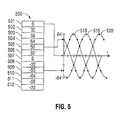
- FIG. 5 is an example illustration of the relationship between a waveform table and polyphase signals generated by a polyphase electrosurgical system in accordance with the present disclosure
- FIG. 6A is an example oblique view of an electrode cluster in accordance with the present disclosure illustrating balanced electric field lines between electrodes;
- FIG. 6B is an example oblique view of an electrode cluster in accordance with the present disclosure illustrating unbalanced electric field lines between electrodes;
- FIG. 7A is an example diagram showing an end view of an electrode configuration of a three-phase electrosurgical system having three electrodes in accordance with the present disclosure
- FIG. 7B is an example diagram showing an end view of an electrode configuration of a three-phase electrosurgical system having six electrodes in accordance with the present disclosure
- FIG. 7C is an example diagram showing an end view of an electrode configuration of a three-phase electrosurgical system having nine electrodes in accordance with the present disclosure
- FIG. 7D is an example diagram showing an end view of an electrode configuration of a four-phase electrosurgical system having four electrodes in accordance with the present disclosure
- FIG. 7E is an example diagram showing an end view of an electrode configuration of a four-phase electrosurgical system having eight electrodes in accordance with the present disclosure.
- FIG. 7F is an example diagram showing an end view of a lattice electrode configuration of a three-phase electrosurgical system having six electrodes in accordance with the present disclosure.
- proximal refers to the end of the apparatus that is closer to the user and the term “distal” refers to the end of the apparatus that is further from the user.
- distal refers to the end of the apparatus that is further from the user.
- a polyphase electrosurgical system 100 in accordance with an embodiment of the present disclosure includes a polyphase RF generator 110 that is operably coupled to an electrosurgical instrument 120 .
- a cluster electrode array 130 is provided at distal end 121 of electrosurgical instrument 120 for delivering electrosurgical energy to tissue of a patient P.
- Polyphase RF generator 110 may be operably coupled to an electrosurgical instrument 120 by a cable 115 , which may be a multi-conductor cable.
- Polyphase electrosurgical system 100 may optionally be configured with at least one return electrode 140 to provide a return path for electrosurgical energy to polyphase RF generator 110 via conductor 150 operably coupled therebetween.
- return electrode 140 may be positioned on the body of a patient at, for example, the leg, buttocks, or other medically-suitable location.
- system 200 aspects of a polyphase electrosurgical system in accordance with an embodiment of the present disclosure are shown as system 200 and include an electrosurgical instrument 210 having a housing 211 adapted for use by a user for performing open, percutaneous, endoscopic, or laparoscopic surgical procedures.
- the distal end 212 of instrument 210 may include electrodes 221 , 222 , and 223 that may be operably and/or independently coupled to separate sources of electrosurgical energy provided by polyphase electrosurgical generator 260 .
- Instrument 210 may additionally include at least one user interface element 230 , which may be used to facilitate control of the generator 260 .
- user interface element 230 may be a momentary pushbutton (e.g., push-on/release-off), toggle pushbutton (e.g., push-on/push-off) or sequence pushbutton (e.g., for stepping through alternative selections). Additionally, or alternatively, user interface element 230 may be a slide switch or continuously variable control, such as a potentiometer.
- momentary pushbutton e.g., push-on/release-off
- toggle pushbutton e.g., push-on/push-off
- sequence pushbutton e.g., for stepping through alternative selections
- user interface element 230 may be a slide switch or continuously variable control, such as a potentiometer.
- Instrument 210 may be operably coupled to polyphase generator 260 by a cable 235 .
- cable 235 may be detachably coupled to the instrument 210 .
- cable 235 may be detachably coupled to polyphase generator 260 via connector 237 .
- a strain relief 236 may be included at the proximal end 213 of instrument 210 .
- a return electrode pad 240 having a return electrode 245 incorporated therewith may be provided.
- Return electrode pad 240 may be operably coupled to polyphase generator 260 by a cable 250 .
- cable 250 may be detachably coupled to the instrument 210 and, additionally or alternatively, cable 250 may be detachably coupled to polyphase generator 260 via connector 251 .
- Return electrode pad 240 may additionally include a connector 246 configured to couple cable 250 thereto.
- Polyphase generator 260 may include at least one user input element 270 , 275 and display element 265 to facilitate user interaction with the system.
- Display element 265 may be any suitable display device, including without limitation an LED display, an LCD display, a graphics display (e.g., flat panel), or an electromechanical indicator.
- FIG. 3 there is illustrated a block diagram of a polyphase electrosurgical generator system 300 in accordance with an embodiment of the present disclosure.
- the system 300 includes a controller module 310 that is operably coupled to a three-phase generator module 330 .
- controller module 310 may be operably coupled to a user interface module 320 and/or an activation control, such as a footswitch 315 .
- the controller 310 , user interface module 320 , and/or generator module 330 may conveniently be arranged in a common housing 305 .
- Generator module 330 provides three RF outputs 331 , 332 , and 333 , corresponding to phase 1 , phase 2 , and phase 3 , respectively, of a polyphase electrosurgical signal.
- Each RF output 331 , 332 , and 333 may be operably coupled to electrodes 351 , 352 , and 353 by conductors 341 , 342 , and 343 , respectively.
- Electrodes 351 , 352 , and 353 are disposed within an instrument housing 350 configured to position electrode tips 356 , 357 , and 358 , at or adjacent to the distal end thereof.
- Instrument housing 350 may be constructed from materials that may include electrically non-conductive material, and may by be configured to electrically insulate electrodes 351 , 352 , and 353 from each other and from non-targeted tissue.
- controller module 310 may receive a user input from user interface module 320 .
- a user may select an amplitude, frequency, and/or phase relationship characterizing the desired electrosurgical signal.
- a user may select a static electrosurgical signal, e.g., one characterized by a continuous steady-state delivery of energy.
- the user may select a dynamically-changing signal, wherein at least one signal parameter changes on a temporal basis, for example without limitation, periodic modulation (e.g., pulse width modulation) and aperiodic modulation (e.g., altering a parameter in a predetermined or arbitrary manner over time).
- Controller module 310 may additionally receive an activation signal from an activation control, such as a footswitch 315 or an activation control included with the instrument housing 350 (not explicitly shown). Upon receipt of an activation signal, controller module causes generator module 330 to begin outputting a polyphase RF signal at output 331 , 332 , and 333 . The polyphase energy is conducted via conductors 341 , 342 , and 343 to electrodes 351 , 352 , and 353 for performing an electrosurgical procedure, such as ablation, on tissue T.
- an activation control such as a footswitch 315 or an activation control included with the instrument housing 350 (not explicitly shown).
- system 400 that includes a processor 410 that is operably coupled to at least one storage device 415 .
- the storage device may be of any type of suitable storage device, including without limitation fixed and/or removable solid state memory devices (such as dynamic RAM, flash memory, or read-only memory), or disk drives (i.e., magnetic, magneto-optical, or optical drives).
- Storage device 415 may contain a waveform table 430 that includes a digitized waveform representation, and may contain a set of programmable instructions configured for execution by processor 410 .
- Processor 410 is operably coupled to digital-to-analog (D/A) converters 441 , 442 , and 443 for converting a digital representation of a waveform into analog form.
- D/A converters 441 , 442 , and 443 are operably coupled to output stages 451 , 452 , and 453 , which collectively may form an energy module 450 .
- Output stages 451 et seq. may be an amplifier for amplifying the output of D/A converters 441 et seq. to the power level required for electrosurgical procedures.
- Output stages 451 may include a low-pass filter. The gain of output stages 451 et seq.
- Outputs of the output stages 451 et seq. are operably coupled to electrodes 471 , 472 , and 473 via conductors 461 , 462 , and 463 for delivering electrosurgical energy to the operative site.
- a return electrode 480 and corresponding return conductor 481 may be operably coupled to energy module 450 .
- processor 410 may be operably coupled to a display device 420 , a user interface 425 , and at least one activation control 435 that may be, for example, a footswitch or a handswitch.
- Processor 410 may be configured to perform a set of programmable instructions for receiving inputs from user interface 425 and/or activation control 435 , and for causing operational information to be displayed on display device 420 .
- processor 410 may be configured to read waveform data from waveform table 430 and cause the waveform data to be converted into analog form by D/A converters 441 et seq.
- processor 410 may retrieve waveform data from waveform table 430 from three separate table locations.
- the offset between the separate table locations from which waveform data is retrieved may be the number of waveform samples corresponding to the desired phase difference, which, in the present example, is 120°.
- the phase difference among and between the individuals may thus be tailored by varying this offset.
- the 120 samples representing a single period of the electrosurgical polyphase signal must be read and converted in a 2 ⁇ s time interval, which correspond to a rate of 16.7 ns per sample, or a sample frequency of 60 mHz.
- the frequency of one or more individual polyphase signal may be adjusted by altering the rate at which waveform data is delivered to, and converted by, a D/A converter 441 et seq.
- the phase and amplitude relationships among and between the polyphase signals may be adjusted by, for example, processor 410 and/or energy module 450 to achieve a target return electrode 480 current.
- a target return electrode current may be a minimal or nearly zero current.
- a software algorithm (not explicitly shown) adapted to be executed by processor 410 receives an input corresponding to the return electrode 480 current. In response thereto, the algorithm may alter one or more of the phase and/or amplitude of a polyphase signal to minimize or nearly eliminate the return electrode 480 current.
- Waveform table 530 includes waveform data representing one period of a sine wave having twelve samples 501 - 512 , and having maximum and minimum values scaled to +64 and ⁇ 64 units, respectively.
- phase 1 is generated by D/A converter 441 from samples beginning at sample 501
- phase 2 is generated by D/A converter 442 from samples initially indexed at 505
- phase 3 is generated by D/A converter 443 from samples indexed beginning at 509 .
- Waveform table 530 may be organized as a circular table, that is, after the final sample is reached, an index “wraps” back to the beginning of the table, i.e., sample 501 . In this manner a continuous waveform may be generated.
- the respective phase difference between individual polyphase signals may be altered by altering the table offset accordingly.
- table 530 may include greater or fewer samples, which may be scaled in any suitable manner, to correspond with, for example, the desired minimum phase angle resolution, or the amplitude resolution of D/A converter 441 et seq.
- FIGS. 6A and 6B example embodiments in accordance with the present disclosure are presented wherein electric field lines representative of current flow are illustrated.
- return electrode 625 may be coupled to polyphase RF generator (not shown) via conductor 626 .
- FIG. 6A depicts a polyphase electrosurgical probe 600 having a three-phase electrode cluster that includes electrodes 611 , 612 , and 613 that are shown delivering polyphase electrosurgical energy to tissue T in a balanced mode.
- the polyphase electrosurgical probe 600 in a balanced mode energy flows among and between three-phase electrode cluster formed by electrodes 611 , 612 , and 613 , while negligible or no current flow exists between the three-phase electrode cluster and return electrode 625 .
- the polyphase electrosurgical probe 600 is shown operating in an unbalanced mode, wherein energy flows among and between the three-phase electrode cluster as shown by representative current flow lines 631 , 632 , and 633 and between the electrode cluster and return electrode 625 as shown by representative current flow lines 634 .
- FIGS. 7A-7F various illustrative arrangements of cluster electrodes and attendant current paths are shown.
- a polyphase electrosurgical system accordance with the present disclosure having a three-phase topology may have a cluster electrode array that includes a triangular or delta electrode configuration 710 .
- FIGS. 7B and 7C an electrode configuration of a three-phase electrosurgical system having six electrodes 720 and nine electrodes 730 , respectively, is shown.
- FIGS. 7D and 7E there is shown an exemplary configuration of a four-phase electrosurgical system having four electrodes 740 and eight electrodes 750 , respectively, in accordance with the present disclosure.
- a polyphase cluster electrode 760 may be configured in a linear or lattice-type arrangement.
- the current paths between electrodes operating in a substantially balanced mode are depicted illustratively by 711 , 721 , 731 , 741 , 751 , and 761 , respectively.
- the phase relationship among and between multiple electrodes may be arbitrarily configured or patterned to tailor energy delivery patterns to achieve a particular ablation region shape.
Landscapes
- Health & Medical Sciences (AREA)
- Surgery (AREA)
- Engineering & Computer Science (AREA)
- Life Sciences & Earth Sciences (AREA)
- Biomedical Technology (AREA)
- Otolaryngology (AREA)
- Nuclear Medicine, Radiotherapy & Molecular Imaging (AREA)
- Plasma & Fusion (AREA)
- Physics & Mathematics (AREA)
- Heart & Thoracic Surgery (AREA)
- Medical Informatics (AREA)
- Molecular Biology (AREA)
- Animal Behavior & Ethology (AREA)
- General Health & Medical Sciences (AREA)
- Public Health (AREA)
- Veterinary Medicine (AREA)
- Surgical Instruments (AREA)
Abstract
Description
Claims (17)
Priority Applications (3)
| Application Number | Priority Date | Filing Date | Title |
|---|---|---|---|
| US12/184,556 US9700366B2 (en) | 2008-08-01 | 2008-08-01 | Polyphase electrosurgical system and method |
| EP09009860.9A EP2149342B1 (en) | 2008-08-01 | 2009-07-30 | Polyphase electrosurgical system |
| JP2009178920A JP5596944B2 (en) | 2008-08-01 | 2009-07-31 | Multiphase electrosurgical system and method |
Applications Claiming Priority (1)
| Application Number | Priority Date | Filing Date | Title |
|---|---|---|---|
| US12/184,556 US9700366B2 (en) | 2008-08-01 | 2008-08-01 | Polyphase electrosurgical system and method |
Publications (2)
| Publication Number | Publication Date |
|---|---|
| US20100030210A1 US20100030210A1 (en) | 2010-02-04 |
| US9700366B2 true US9700366B2 (en) | 2017-07-11 |
Family
ID=41376414
Family Applications (1)
| Application Number | Title | Priority Date | Filing Date |
|---|---|---|---|
| US12/184,556 Expired - Fee Related US9700366B2 (en) | 2008-08-01 | 2008-08-01 | Polyphase electrosurgical system and method |
Country Status (3)
| Country | Link |
|---|---|
| US (1) | US9700366B2 (en) |
| EP (1) | EP2149342B1 (en) |
| JP (1) | JP5596944B2 (en) |
Cited By (7)
| Publication number | Priority date | Publication date | Assignee | Title |
|---|---|---|---|---|
| US10022186B2 (en) | 2008-08-28 | 2018-07-17 | Covidien Lp | Microwave antenna with cooled handle |
| EP3769711A1 (en) * | 2018-01-17 | 2021-01-27 | Covidien LP | Surgical instruments incorporating ultrasonic and electrosurgical functionality |
| US11478267B2 (en) | 2018-01-17 | 2022-10-25 | Covidien Lp | Surgical instruments incorporating ultrasonic and electrosurgical functionality |
| US11564733B2 (en) | 2018-01-17 | 2023-01-31 | Covidien Lp | Surgical instruments incorporating ultrasonic and electrosurgical functionality |
| US11589889B2 (en) | 2018-01-17 | 2023-02-28 | Covidien Lp | Surgical instruments incorporating ultrasonic and electrosurgical functionality |
| US12318133B2 (en) | 2008-01-23 | 2025-06-03 | Covidien Lp | Choked microwave antenna |
| US12539134B2 (en) | 2021-05-17 | 2026-02-03 | Covidien Lp | Surgical instruments, systems, and methods incorporating ultrasonic and three-phase electrosurgical functionality |
Families Citing this family (75)
| Publication number | Priority date | Publication date | Assignee | Title |
|---|---|---|---|---|
| US7137980B2 (en) | 1998-10-23 | 2006-11-21 | Sherwood Services Ag | Method and system for controlling output of RF medical generator |
| US7044948B2 (en) | 2002-12-10 | 2006-05-16 | Sherwood Services Ag | Circuit for controlling arc energy from an electrosurgical generator |
| EP1617776B1 (en) | 2003-05-01 | 2015-09-02 | Covidien AG | System for programing and controlling an electrosurgical generator system |
| CA2542798C (en) | 2003-10-23 | 2015-06-23 | Sherwood Services Ag | Thermocouple measurement circuit |
| US7396336B2 (en) | 2003-10-30 | 2008-07-08 | Sherwood Services Ag | Switched resonant ultrasonic power amplifier system |
| US9277955B2 (en) * | 2010-04-09 | 2016-03-08 | Vessix Vascular, Inc. | Power generating and control apparatus for the treatment of tissue |
| US7947039B2 (en) | 2005-12-12 | 2011-05-24 | Covidien Ag | Laparoscopic apparatus for performing electrosurgical procedures |
| CA2574934C (en) | 2006-01-24 | 2015-12-29 | Sherwood Services Ag | System and method for closed loop monitoring of monopolar electrosurgical apparatus |
| US7651492B2 (en) | 2006-04-24 | 2010-01-26 | Covidien Ag | Arc based adaptive control system for an electrosurgical unit |
| US7794457B2 (en) | 2006-09-28 | 2010-09-14 | Covidien Ag | Transformer for RF voltage sensing |
| US9622813B2 (en) | 2007-11-01 | 2017-04-18 | Covidien Lp | Method for volume determination and geometric reconstruction |
| US8280525B2 (en) | 2007-11-16 | 2012-10-02 | Vivant Medical, Inc. | Dynamically matched microwave antenna for tissue ablation |
| US8435237B2 (en) | 2008-01-29 | 2013-05-07 | Covidien Lp | Polyp encapsulation system and method |
| US9949794B2 (en) | 2008-03-27 | 2018-04-24 | Covidien Lp | Microwave ablation devices including expandable antennas and methods of use |
| US8192427B2 (en) | 2008-06-09 | 2012-06-05 | Tyco Healthcare Group Lp | Surface ablation process with electrode cooling methods |
| US9700366B2 (en) | 2008-08-01 | 2017-07-11 | Covidien Lp | Polyphase electrosurgical system and method |
| US8403924B2 (en) | 2008-09-03 | 2013-03-26 | Vivant Medical, Inc. | Shielding for an isolation apparatus used in a microwave generator |
| US8262652B2 (en) | 2009-01-12 | 2012-09-11 | Tyco Healthcare Group Lp | Imaginary impedance process monitoring and intelligent shut-off |
| US8197473B2 (en) | 2009-02-20 | 2012-06-12 | Vivant Medical, Inc. | Leaky-wave antennas for medical applications |
| US8202270B2 (en) | 2009-02-20 | 2012-06-19 | Vivant Medical, Inc. | Leaky-wave antennas for medical applications |
| US9277969B2 (en) | 2009-04-01 | 2016-03-08 | Covidien Lp | Microwave ablation system with user-controlled ablation size and method of use |
| US8463396B2 (en) | 2009-05-06 | 2013-06-11 | Covidien LLP | Power-stage antenna integrated system with high-strength shaft |
| US8292881B2 (en) | 2009-05-27 | 2012-10-23 | Vivant Medical, Inc. | Narrow gauge high strength choked wet tip microwave ablation antenna |
| US8235981B2 (en) | 2009-06-02 | 2012-08-07 | Vivant Medical, Inc. | Electrosurgical devices with directional radiation pattern |
| USD634010S1 (en) | 2009-08-05 | 2011-03-08 | Vivant Medical, Inc. | Medical device indicator guide |
| US9031668B2 (en) * | 2009-08-06 | 2015-05-12 | Covidien Lp | Vented positioner and spacer and method of use |
| US8069553B2 (en) | 2009-09-09 | 2011-12-06 | Vivant Medical, Inc. | Method for constructing a dipole antenna |
| US9113925B2 (en) * | 2009-09-09 | 2015-08-25 | Covidien Lp | System and method for performing an ablation procedure |
| KR101093014B1 (en) | 2009-09-11 | 2011-12-13 | 대양의료기(주) | Skin care treatment device using 3-phase high frequency |
| US8355803B2 (en) | 2009-09-16 | 2013-01-15 | Vivant Medical, Inc. | Perfused core dielectrically loaded dipole microwave antenna probe |
| US9095359B2 (en) | 2009-09-18 | 2015-08-04 | Covidien Lp | Tissue ablation system with energy distribution |
| US8377054B2 (en) * | 2009-09-24 | 2013-02-19 | Covidien Lp | Automatic control circuit for use in an electrosurgical generator |
| US8685015B2 (en) * | 2009-09-24 | 2014-04-01 | Covidien Lp | System and method for multi-pole phase-shifted radio frequency application |
| US8394087B2 (en) * | 2009-09-24 | 2013-03-12 | Vivant Medical, Inc. | Optical detection of interrupted fluid flow to ablation probe |
| US9113926B2 (en) | 2009-09-29 | 2015-08-25 | Covidien Lp | Management of voltage standing wave ratio at skin surface during microwave ablation |
| US8556889B2 (en) | 2009-09-29 | 2013-10-15 | Covidien Lp | Flow rate monitor for fluid cooled microwave ablation probe |
| US8568401B2 (en) * | 2009-10-27 | 2013-10-29 | Covidien Lp | System for monitoring ablation size |
| US8430871B2 (en) | 2009-10-28 | 2013-04-30 | Covidien Lp | System and method for monitoring ablation size |
| US8382750B2 (en) | 2009-10-28 | 2013-02-26 | Vivant Medical, Inc. | System and method for monitoring ablation size |
| US8610501B2 (en) | 2009-11-16 | 2013-12-17 | Covidien Lp | Class resonant-H electrosurgical generators |
| US10039588B2 (en) | 2009-12-16 | 2018-08-07 | Covidien Lp | System and method for tissue sealing |
| US8974449B2 (en) | 2010-07-16 | 2015-03-10 | Covidien Lp | Dual antenna assembly with user-controlled phase shifting |
| USD673685S1 (en) | 2010-09-08 | 2013-01-01 | Vivant Medical, Inc. | Microwave device spacer and positioner with arcuate slot |
| US8945144B2 (en) | 2010-09-08 | 2015-02-03 | Covidien Lp | Microwave spacers and method of use |
| US8968289B2 (en) | 2010-10-22 | 2015-03-03 | Covidien Lp | Microwave spacers and methods of use |
| EP2564895B1 (en) * | 2011-09-05 | 2015-11-18 | Venus Concept Ltd | An improved esthetic device for beautifying skin |
| EP2788078B1 (en) | 2011-12-09 | 2020-09-02 | Metavention, Inc. | Therapeutic neuromodulation of the hepatic system |
| US9119648B2 (en) | 2012-01-06 | 2015-09-01 | Covidien Lp | System and method for treating tissue using an expandable antenna |
| US9113931B2 (en) | 2012-01-06 | 2015-08-25 | Covidien Lp | System and method for treating tissue using an expandable antenna |
| US10076383B2 (en) | 2012-01-25 | 2018-09-18 | Covidien Lp | Electrosurgical device having a multiplexer |
| US20150111918A1 (en) | 2012-03-08 | 2015-04-23 | Medtronic Ardian Luxembourg S.a.r.l | Immune system neuromodulation and associated systems and methods |
| WO2014036160A2 (en) * | 2012-08-28 | 2014-03-06 | Boston Scientific Scimed, Inc. | Renal nerve modulation and ablation catheter electrode design |
| US20160128767A1 (en) | 2013-06-05 | 2016-05-12 | Metavention, Inc. | Modulation of targeted nerve fibers |
| US9872719B2 (en) | 2013-07-24 | 2018-01-23 | Covidien Lp | Systems and methods for generating electrosurgical energy using a multistage power converter |
| US9636165B2 (en) | 2013-07-29 | 2017-05-02 | Covidien Lp | Systems and methods for measuring tissue impedance through an electrosurgical cable |
| US9949783B2 (en) * | 2014-04-04 | 2018-04-24 | Covidien Lp | Systems and methods for optimizing emissions from simultaneous activation of electrosurgery generators |
| US9974595B2 (en) * | 2014-04-04 | 2018-05-22 | Covidien Lp | Systems and methods for optimizing emissions from simultaneous activation of electrosurgery generators |
| US9762273B2 (en) * | 2014-09-12 | 2017-09-12 | The Trustees Of Columbia University In The City Of New York | Circuits and methods for detecting interferers |
| AU2015358385B2 (en) | 2014-12-03 | 2020-09-03 | Medtronic Ireland Manufacturing Unlimited Company | Systems and methods for modulating nerves or other tissue |
| GB2534555A (en) * | 2015-01-20 | 2016-08-03 | Kathrein Werke Kg | Method and system for the automated alignment of antennas |
| US10758741B2 (en) | 2015-04-14 | 2020-09-01 | Vasily Dronov | System and method for selective treatment of skin and subcutaneous fat using a single frequency dual mode radio frequency antenna device |
| US9536758B1 (en) | 2016-05-26 | 2017-01-03 | Anand Deo | Time-varying frequency powered semiconductor substrate heat source |
| US11152232B2 (en) | 2016-05-26 | 2021-10-19 | Anand Deo | Frequency and phase controlled transducers and sensing |
| US12491111B2 (en) | 2016-05-26 | 2025-12-09 | Anand Deo | Medical instrument for in vivo heat source |
| US10524859B2 (en) | 2016-06-07 | 2020-01-07 | Metavention, Inc. | Therapeutic tissue modulation devices and methods |
| GB201705171D0 (en) * | 2017-03-30 | 2017-05-17 | Creo Medical Ltd | Elecrosurgical instrument |
| GB2564397B (en) * | 2017-07-06 | 2021-12-08 | Airspan Ip Holdco Llc | Scanning in a wireless network |
| US10945781B2 (en) * | 2017-09-07 | 2021-03-16 | Biosense Webster (Israel) Ltd. | Variable phase generation and detection for radio-frequency (RF) ablation |
| WO2020101918A1 (en) * | 2018-11-13 | 2020-05-22 | St. Jude Medical, Cardiology Division, Inc. | Phased array radiofrequency ablation catheter and method of its manufacture |
| US11826088B2 (en) | 2018-12-28 | 2023-11-28 | Biosense Webster (Israel) Ltd. | Adjusting phases of multiphase ablation generator to detect contact |
| US20200289188A1 (en) * | 2019-03-15 | 2020-09-17 | Boston Scientific Scimed, Inc. | Spatially multiplexed waveform for selective cell ablation |
| US12226143B2 (en) | 2020-06-22 | 2025-02-18 | Covidien Lp | Universal surgical footswitch toggling |
| DE102021117566A1 (en) | 2021-07-07 | 2023-01-12 | Karl Storz Se & Co. Kg | Active electrode for electrosurgical instrument |
| US11729869B2 (en) | 2021-10-13 | 2023-08-15 | Anand Deo | Conformable polymer for frequency-selectable heating locations |
| DE102022125714A1 (en) | 2022-10-05 | 2024-04-11 | Karl Storz Se & Co. Kg | Electrosurgical tool and method of manufacturing |
Citations (87)
| Publication number | Priority date | Publication date | Assignee | Title |
|---|---|---|---|---|
| SU166452A1 (en) | В. А. Костров , Л. В. Смирнов | STOMATOLOGICAL DIATHERMOKOAGULATOR | ||
| DE179607C (en) | 1906-11-12 | |||
| DE390937C (en) | 1922-10-13 | 1924-03-03 | Adolf Erb | Device for internal heating of furnace furnaces for hardening, tempering, annealing, quenching and melting |
| US2331247A (en) | 1943-03-11 | 1943-10-05 | Symons Clamp & Mfg Company | Shore head structure |
| GB607850A (en) | 1946-04-01 | 1948-09-06 | William George Curwain | Electric connectors |
| GB702510A (en) | 1951-03-24 | 1954-01-20 | Foxboro Co | Improvements in temperature responsive instruments |
| GB855459A (en) | 1958-04-11 | 1960-11-30 | Keeler Optical Products Ltd | Improvements in or relating to electro-surgical apparatus |
| DE1099658B (en) | 1959-04-29 | 1961-02-16 | Siemens Reiniger Werke Ag | Automatic switch-on device for high-frequency surgical devices |
| FR1275415A (en) | 1960-09-26 | 1961-11-10 | Device for detecting disturbances for electrical installations, in particular electrosurgery | |
| GB902775A (en) | 1959-05-16 | 1962-08-09 | Kathleen Zilla Rumble | Improvements in or relating to electrical plugs |
| DE1139927B (en) | 1961-01-03 | 1962-11-22 | Friedrich Laber | High-frequency surgical device |
| DE1149832B (en) | 1961-02-25 | 1963-06-06 | Siemens Reiniger Werke Ag | High frequency surgical apparatus |
| FR1347865A (en) | 1962-11-22 | 1964-01-04 | Improvements to diathermo-coagulation devices | |
| DE1439302A1 (en) | 1963-10-26 | 1969-01-23 | Siemens Ag | High-frequency surgical device |
| US3514689A (en) | 1968-08-21 | 1970-05-26 | United Aircraft Corp | Three-phase ac-operated dc power supply |
| US3697808A (en) | 1970-11-23 | 1972-10-10 | Safety Co The | System for monitoring chassis potential and ground continuity |
| US3766434A (en) | 1971-08-09 | 1973-10-16 | S Sherman | Safety power distribution system |
| DE2439587A1 (en) | 1973-08-23 | 1975-02-27 | Matburn Holdings Ltd | ELECTROSURGICAL DEVICE |
| DE2455174A1 (en) | 1973-11-21 | 1975-05-22 | Termiflex Corp | INPUT / OUTPUT DEVICE FOR DATA EXCHANGE WITH DATA PROCESSING DEVICES |
| DE2407559A1 (en) | 1974-02-16 | 1975-08-28 | Dornier System Gmbh | Tissue heat treatment probe - has water cooling system which ensures heat development only in treated tissues |
| DE2602517A1 (en) | 1975-01-23 | 1976-07-29 | Dentsply Int Inc | ELECTROSURGICAL DEVICE |
| DE2504280A1 (en) | 1975-02-01 | 1976-08-05 | Hans Heinrich Prof Dr Meinke | DEVICE FOR ELECTRIC TISSUE CUTTING IN SURGERY |
| FR2313708A1 (en) | 1975-06-02 | 1976-12-31 | Sybron Corp | Electro surgical instrument impulse control circuit - has potentiometer between patient electrodes and threshold switch for excessive voltage |
| DE2540968A1 (en) | 1975-09-13 | 1977-03-17 | Erbe Elektromedizin | Circuit for bipolar coagulation tweezers - permits preparation of tissues prior to coagulation |
| FR2364461A1 (en) | 1976-09-09 | 1978-04-07 | Valleylab Inc | ELECTROSURGICAL EQUIPMENT SAFETY CIRCUIT AND ITS PROCESS FOR USE |
| DE2820908A1 (en) | 1977-05-16 | 1978-11-23 | Joseph Skovajsa | DEVICE FOR THE LOCAL TREATMENT OF A PATIENT IN PARTICULAR FOR ACUPUNCTURE OR AURICULAR THERAPY |
| DE2803275A1 (en) | 1978-01-26 | 1979-08-02 | Aesculap Werke Ag | HF surgical appts. with active treatment and patient electrodes - has sensor switching generator to small voltage when hand-operated switch is closed |
| DE2823291A1 (en) | 1978-05-27 | 1979-11-29 | Rainer Ing Grad Koch | Coagulation instrument automatic HF switching circuit - has first lead to potentiometer and second to transistor base |
| SU727201A2 (en) | 1977-11-02 | 1980-04-15 | Киевский Научно-Исследовательский Институт Нейрохирургии | Electric surgical apparatus |
| DE2946728A1 (en) | 1979-11-20 | 1981-05-27 | Erbe Elektromedizin GmbH & Co KG, 7400 Tübingen | HF surgical appts. for use with endoscope - provides cutting or coagulation current at preset intervals and of selected duration |
| DE3143421A1 (en) | 1980-11-04 | 1982-05-27 | The Agency of Industrial Science and Technology, Tokyo | Laser scalpel |
| DE3045996A1 (en) | 1980-12-05 | 1982-07-08 | Medic Eschmann Handelsgesellschaft für medizinische Instrumente mbH, 2000 Hamburg | Electro-surgical scalpel instrument - has power supply remotely controlled by surgeon |
| FR2502935A1 (en) | 1981-03-31 | 1982-10-08 | Dolley Roger | Diathermic knife for coagulating tissues - has monitoring current added to HF coagulating current in order to control end of operation as function or resistance of coagulating tissues |
| DE3120102A1 (en) | 1981-05-20 | 1982-12-09 | F.L. Fischer GmbH & Co, 7800 Freiburg | ARRANGEMENT FOR HIGH-FREQUENCY COAGULATION OF EGG WHITE FOR SURGICAL PURPOSES |
| FR2517953A1 (en) | 1981-12-10 | 1983-06-17 | Alvar Electronic | Diaphanometer for optical examination of breast tissue structure - measures tissue transparency using two plates and optical fibre bundle cooperating with photoelectric cells |
| US4415763A (en) | 1980-11-14 | 1983-11-15 | Westinghouse Electric Corp. | Gas-insulated transmission line having improved outer enclosure |
| US4532924A (en) | 1980-05-13 | 1985-08-06 | American Hospital Supply Corporation | Multipolar electrosurgical device and method |
| US4572190A (en) | 1983-05-26 | 1986-02-25 | Cgr/Mev | Hyperthermia apparatus |
| GB2164473A (en) | 1984-09-10 | 1986-03-19 | Bard Inc C R | Electrosurgical generator power supply |
| FR2573301A1 (en) | 1984-11-16 | 1986-05-23 | Lamidey Gilles | Surgical forceps and its control and monitoring apparatus |
| DE3510586A1 (en) | 1985-03-23 | 1986-10-02 | Erbe Elektromedizin GmbH, 7400 Tübingen | Control device for a high-frequency surgical instrument |
| US4630218A (en) | 1983-04-22 | 1986-12-16 | Cooper Industries, Inc. | Current measuring apparatus |
| US4672980A (en) | 1980-04-02 | 1987-06-16 | Bsd Medical Corporation | System and method for creating hyperthermia in tissue |
| DE3604823A1 (en) | 1986-02-15 | 1987-08-27 | Flachenecker Gerhard | HIGH FREQUENCY GENERATOR WITH AUTOMATIC PERFORMANCE CONTROL FOR HIGH FREQUENCY SURGERY |
| EP0246350A1 (en) | 1986-05-23 | 1987-11-25 | Erbe Elektromedizin GmbH. | Coagulation electrode |
| US4785829A (en) | 1985-12-10 | 1988-11-22 | C.G.R Mev | Apparatus for hyperthermic treatment |
| EP0310431A2 (en) | 1987-09-30 | 1989-04-05 | Valleylab, Inc. | Apparatus for providing enhanced tissue fragmentation and/or hemostasis |
| EP0325456A2 (en) | 1988-01-20 | 1989-07-26 | G2 Design Limited | Diathermy unit |
| GB2214430A (en) | 1988-01-20 | 1989-09-06 | Nigel Mark Goble | Diathermy unit |
| DE3904558A1 (en) | 1989-02-15 | 1990-08-23 | Flachenecker Gerhard | AUTOMATICALLY POWER-CONTROLLED HIGH-FREQUENCY GENERATOR FOR HIGH-FREQUENCY SURGERY |
| EP0390937A1 (en) | 1989-04-01 | 1990-10-10 | Erbe Elektromedizin GmbH | Device for the surveillance of the adherence of neutral electrodes in high-frequency surgery |
| DE3942998A1 (en) | 1989-12-27 | 1991-07-04 | Delma Elektro Med App | Electro-surgical HF instrument for contact coagulation - has monitoring circuit evaluating HF voltage at electrodes and delivering switch=off signal |
| US5220927A (en) | 1988-07-28 | 1993-06-22 | Bsd Medical Corporation | Urethral inserted applicator for prostate hyperthermia |
| EP0556705A1 (en) | 1992-02-20 | 1993-08-25 | DELMA ELEKTRO-UND MEDIZINISCHE APPARATEBAU GESELLSCHAFT mbH | High frequency surgery device |
| EP0608609A2 (en) | 1992-12-01 | 1994-08-03 | Cardiac Pathways Corporation | Catheter for RF ablation with cooled electrode and method |
| US5354325A (en) | 1991-07-26 | 1994-10-11 | Institut National De La Sante Et De La Recherche Medicale | System for internal heat treatment of a specific body and its use |
| US5383917A (en) * | 1991-07-05 | 1995-01-24 | Jawahar M. Desai | Device and method for multi-phase radio-frequency ablation |
| DE4339049A1 (en) | 1993-11-16 | 1995-05-18 | Erbe Elektromedizin | Surgical system and instruments configuration device |
| WO1995025472A1 (en) | 1994-03-23 | 1995-09-28 | Vidamed, Inc. | Dual-channel rf power delivery system |
| JPH08299356A (en) | 1995-05-11 | 1996-11-19 | Olympus Optical Co Ltd | Electric surgical operation device |
| WO1996039088A1 (en) | 1995-06-06 | 1996-12-12 | Valleylab Inc. | Digital waveform generation for electrosurgical generators |
| US5602812A (en) * | 1994-11-24 | 1997-02-11 | Teac Corporation | Reproducing rate control apparatus for optical disk |
| US5620481A (en) | 1991-07-05 | 1997-04-15 | Desai; Jawahar M. | Device for multi-phase radio-frequency ablation |
| WO1998007378A1 (en) | 1996-08-23 | 1998-02-26 | Team Medical L.L.C. | Improved electrosurgical generator |
| EP0836868A2 (en) | 1996-10-18 | 1998-04-22 | Gebr. Berchtold GmbH & Co. | High frequency surgical apparatus and method for operating same |
| DE19717411A1 (en) | 1997-04-25 | 1998-11-05 | Aesculap Ag & Co Kg | Monitoring of thermal loading of patient tissue in contact region of neutral electrode of HF treatment unit |
| EP0880220A2 (en) | 1997-05-19 | 1998-11-25 | TRW Inc. | A phase staggered full-bridge converter with soft-PWM switching |
| GB2331247A (en) | 1997-11-13 | 1999-05-19 | John Hugh Davey Walton | Surgical diathermy apparatus |
| WO1999056647A1 (en) | 1998-05-05 | 1999-11-11 | Cardiac Pacemakers, Inc. | Rf ablation apparatus having high output impedance drivers |
| EP0833592B1 (en) | 1995-06-06 | 2000-05-03 | Sherwood Services AG | Exit spark control for an electrosurgical generator |
| US6059778A (en) | 1998-05-05 | 2000-05-09 | Cardiac Pacemakers, Inc. | RF ablation apparatus and method using unipolar and bipolar techniques |
| DE19848540A1 (en) | 1998-10-21 | 2000-05-25 | Reinhard Kalfhaus | Circuit layout and method for operating a single- or multiphase current inverter connects an AC voltage output to a primary winding and current and a working resistance to a transformer's secondary winding and current. |
| EP1051948A2 (en) | 1999-04-23 | 2000-11-15 | Sherwood Services AG | Automatic activation of electrosurgical generator bipolar output |
| GB2358934A (en) | 2000-02-05 | 2001-08-08 | Smiths Group Plc | Cable Testing |
| US20030069619A1 (en) * | 2000-06-20 | 2003-04-10 | Fenn Alan J. | System and method for heating the prostate gland to treat and prevent the growth and spread of prostate tumors |
| US20030195501A1 (en) * | 1998-05-05 | 2003-10-16 | Sherman Marshall L. | RF ablation system and method having automatic temperature control |
| JP2004160084A (en) | 2002-11-15 | 2004-06-10 | Aloka Co Ltd | Galvanosurgery apparatus |
| US6794929B2 (en) | 2000-03-28 | 2004-09-21 | International Rectifier Corporation | Active filter for reduction of common mode current |
| EP1465037A2 (en) | 1998-12-30 | 2004-10-06 | Advanced Energy Industries, Inc. | A method and system for alternating current regulation |
| US20050043726A1 (en) * | 2001-03-07 | 2005-02-24 | Mchale Anthony Patrick | Device II |
| EP1366724B1 (en) | 1995-12-08 | 2006-01-11 | C.R. Bard Inc. | Radio frequency energy delivery system for multipolar electrode catheters |
| US20060015095A1 (en) | 2002-05-27 | 2006-01-19 | Kai Desinger | Device for electrosurgically destroying body tissue |
| EP1707144A1 (en) | 2005-03-31 | 2006-10-04 | Sherwood Services AG | Method and system for compensating for external impedance of energy carrying component when controlling electrosurgical generator |
| US7145757B2 (en) | 2004-01-13 | 2006-12-05 | Eaton Corporation | System for eliminating arcing faults and power distribution system employing the same |
| US7151964B2 (en) | 1991-07-05 | 2006-12-19 | Desai Jawahar M | Device and method for multi-phase radio-frequency ablation |
| US20070088413A1 (en) * | 2005-10-19 | 2007-04-19 | Thermage, Inc. | Treatment apparatus and methods for delivering energy at multiple selectable depths in tissue |
| EP2149342A1 (en) | 2008-08-01 | 2010-02-03 | Tyco Healthcare Group, LP | Polyphase electrosurgical system and method |
Family Cites Families (6)
| Publication number | Priority date | Publication date | Assignee | Title |
|---|---|---|---|---|
| KR920700267A (en) * | 1989-02-28 | 1992-02-19 | 모리구찌 엔지 | Method and apparatus for manufacturing carbon black |
| US6530922B2 (en) | 1993-12-15 | 2003-03-11 | Sherwood Services Ag | Cluster ablation electrode system |
| ATE352999T1 (en) | 1995-05-04 | 2007-02-15 | Sherwood Serv Ag | SURGICAL SYSTEM WITH COOLED ELECTRODE TIP |
| CA2297846C (en) * | 1997-07-25 | 2009-04-28 | Eric R. Cosman | Cluster ablation electrode system |
| KR100739002B1 (en) * | 2006-04-28 | 2007-07-12 | (주) 태웅메디칼 | Multi RF Generator for High Frequency Thermal Therapy |
| JP5198466B2 (en) * | 2006-12-06 | 2013-05-15 | ボストン サイエンティフィック リミテッド | Tissue ablation energy generator using pulse modulated radio frequency energy |
-
2008
- 2008-08-01 US US12/184,556 patent/US9700366B2/en not_active Expired - Fee Related
-
2009
- 2009-07-30 EP EP09009860.9A patent/EP2149342B1/en not_active Not-in-force
- 2009-07-31 JP JP2009178920A patent/JP5596944B2/en not_active Expired - Fee Related
Patent Citations (91)
| Publication number | Priority date | Publication date | Assignee | Title |
|---|---|---|---|---|
| SU166452A1 (en) | В. А. Костров , Л. В. Смирнов | STOMATOLOGICAL DIATHERMOKOAGULATOR | ||
| DE179607C (en) | 1906-11-12 | |||
| DE390937C (en) | 1922-10-13 | 1924-03-03 | Adolf Erb | Device for internal heating of furnace furnaces for hardening, tempering, annealing, quenching and melting |
| US2331247A (en) | 1943-03-11 | 1943-10-05 | Symons Clamp & Mfg Company | Shore head structure |
| GB607850A (en) | 1946-04-01 | 1948-09-06 | William George Curwain | Electric connectors |
| GB702510A (en) | 1951-03-24 | 1954-01-20 | Foxboro Co | Improvements in temperature responsive instruments |
| GB855459A (en) | 1958-04-11 | 1960-11-30 | Keeler Optical Products Ltd | Improvements in or relating to electro-surgical apparatus |
| DE1099658B (en) | 1959-04-29 | 1961-02-16 | Siemens Reiniger Werke Ag | Automatic switch-on device for high-frequency surgical devices |
| GB902775A (en) | 1959-05-16 | 1962-08-09 | Kathleen Zilla Rumble | Improvements in or relating to electrical plugs |
| FR1275415A (en) | 1960-09-26 | 1961-11-10 | Device for detecting disturbances for electrical installations, in particular electrosurgery | |
| DE1139927B (en) | 1961-01-03 | 1962-11-22 | Friedrich Laber | High-frequency surgical device |
| DE1149832B (en) | 1961-02-25 | 1963-06-06 | Siemens Reiniger Werke Ag | High frequency surgical apparatus |
| FR1347865A (en) | 1962-11-22 | 1964-01-04 | Improvements to diathermo-coagulation devices | |
| DE1439302A1 (en) | 1963-10-26 | 1969-01-23 | Siemens Ag | High-frequency surgical device |
| US3514689A (en) | 1968-08-21 | 1970-05-26 | United Aircraft Corp | Three-phase ac-operated dc power supply |
| US3697808A (en) | 1970-11-23 | 1972-10-10 | Safety Co The | System for monitoring chassis potential and ground continuity |
| US3766434A (en) | 1971-08-09 | 1973-10-16 | S Sherman | Safety power distribution system |
| DE2439587A1 (en) | 1973-08-23 | 1975-02-27 | Matburn Holdings Ltd | ELECTROSURGICAL DEVICE |
| DE2455174A1 (en) | 1973-11-21 | 1975-05-22 | Termiflex Corp | INPUT / OUTPUT DEVICE FOR DATA EXCHANGE WITH DATA PROCESSING DEVICES |
| DE2407559A1 (en) | 1974-02-16 | 1975-08-28 | Dornier System Gmbh | Tissue heat treatment probe - has water cooling system which ensures heat development only in treated tissues |
| DE2602517A1 (en) | 1975-01-23 | 1976-07-29 | Dentsply Int Inc | ELECTROSURGICAL DEVICE |
| DE2504280A1 (en) | 1975-02-01 | 1976-08-05 | Hans Heinrich Prof Dr Meinke | DEVICE FOR ELECTRIC TISSUE CUTTING IN SURGERY |
| FR2313708A1 (en) | 1975-06-02 | 1976-12-31 | Sybron Corp | Electro surgical instrument impulse control circuit - has potentiometer between patient electrodes and threshold switch for excessive voltage |
| DE2540968A1 (en) | 1975-09-13 | 1977-03-17 | Erbe Elektromedizin | Circuit for bipolar coagulation tweezers - permits preparation of tissues prior to coagulation |
| FR2364461A1 (en) | 1976-09-09 | 1978-04-07 | Valleylab Inc | ELECTROSURGICAL EQUIPMENT SAFETY CIRCUIT AND ITS PROCESS FOR USE |
| DE2820908A1 (en) | 1977-05-16 | 1978-11-23 | Joseph Skovajsa | DEVICE FOR THE LOCAL TREATMENT OF A PATIENT IN PARTICULAR FOR ACUPUNCTURE OR AURICULAR THERAPY |
| SU727201A2 (en) | 1977-11-02 | 1980-04-15 | Киевский Научно-Исследовательский Институт Нейрохирургии | Electric surgical apparatus |
| DE2803275A1 (en) | 1978-01-26 | 1979-08-02 | Aesculap Werke Ag | HF surgical appts. with active treatment and patient electrodes - has sensor switching generator to small voltage when hand-operated switch is closed |
| DE2823291A1 (en) | 1978-05-27 | 1979-11-29 | Rainer Ing Grad Koch | Coagulation instrument automatic HF switching circuit - has first lead to potentiometer and second to transistor base |
| DE2946728A1 (en) | 1979-11-20 | 1981-05-27 | Erbe Elektromedizin GmbH & Co KG, 7400 Tübingen | HF surgical appts. for use with endoscope - provides cutting or coagulation current at preset intervals and of selected duration |
| US4672980A (en) | 1980-04-02 | 1987-06-16 | Bsd Medical Corporation | System and method for creating hyperthermia in tissue |
| US4532924A (en) | 1980-05-13 | 1985-08-06 | American Hospital Supply Corporation | Multipolar electrosurgical device and method |
| DE3143421A1 (en) | 1980-11-04 | 1982-05-27 | The Agency of Industrial Science and Technology, Tokyo | Laser scalpel |
| US4415763A (en) | 1980-11-14 | 1983-11-15 | Westinghouse Electric Corp. | Gas-insulated transmission line having improved outer enclosure |
| DE3045996A1 (en) | 1980-12-05 | 1982-07-08 | Medic Eschmann Handelsgesellschaft für medizinische Instrumente mbH, 2000 Hamburg | Electro-surgical scalpel instrument - has power supply remotely controlled by surgeon |
| FR2502935A1 (en) | 1981-03-31 | 1982-10-08 | Dolley Roger | Diathermic knife for coagulating tissues - has monitoring current added to HF coagulating current in order to control end of operation as function or resistance of coagulating tissues |
| DE3120102A1 (en) | 1981-05-20 | 1982-12-09 | F.L. Fischer GmbH & Co, 7800 Freiburg | ARRANGEMENT FOR HIGH-FREQUENCY COAGULATION OF EGG WHITE FOR SURGICAL PURPOSES |
| FR2517953A1 (en) | 1981-12-10 | 1983-06-17 | Alvar Electronic | Diaphanometer for optical examination of breast tissue structure - measures tissue transparency using two plates and optical fibre bundle cooperating with photoelectric cells |
| US4630218A (en) | 1983-04-22 | 1986-12-16 | Cooper Industries, Inc. | Current measuring apparatus |
| US4572190A (en) | 1983-05-26 | 1986-02-25 | Cgr/Mev | Hyperthermia apparatus |
| GB2164473A (en) | 1984-09-10 | 1986-03-19 | Bard Inc C R | Electrosurgical generator power supply |
| FR2573301A1 (en) | 1984-11-16 | 1986-05-23 | Lamidey Gilles | Surgical forceps and its control and monitoring apparatus |
| DE3510586A1 (en) | 1985-03-23 | 1986-10-02 | Erbe Elektromedizin GmbH, 7400 Tübingen | Control device for a high-frequency surgical instrument |
| US4785829A (en) | 1985-12-10 | 1988-11-22 | C.G.R Mev | Apparatus for hyperthermic treatment |
| DE3604823A1 (en) | 1986-02-15 | 1987-08-27 | Flachenecker Gerhard | HIGH FREQUENCY GENERATOR WITH AUTOMATIC PERFORMANCE CONTROL FOR HIGH FREQUENCY SURGERY |
| EP0246350A1 (en) | 1986-05-23 | 1987-11-25 | Erbe Elektromedizin GmbH. | Coagulation electrode |
| EP0310431A2 (en) | 1987-09-30 | 1989-04-05 | Valleylab, Inc. | Apparatus for providing enhanced tissue fragmentation and/or hemostasis |
| EP0325456A2 (en) | 1988-01-20 | 1989-07-26 | G2 Design Limited | Diathermy unit |
| GB2214430A (en) | 1988-01-20 | 1989-09-06 | Nigel Mark Goble | Diathermy unit |
| US5220927A (en) | 1988-07-28 | 1993-06-22 | Bsd Medical Corporation | Urethral inserted applicator for prostate hyperthermia |
| DE3904558A1 (en) | 1989-02-15 | 1990-08-23 | Flachenecker Gerhard | AUTOMATICALLY POWER-CONTROLLED HIGH-FREQUENCY GENERATOR FOR HIGH-FREQUENCY SURGERY |
| EP0390937A1 (en) | 1989-04-01 | 1990-10-10 | Erbe Elektromedizin GmbH | Device for the surveillance of the adherence of neutral electrodes in high-frequency surgery |
| DE3942998A1 (en) | 1989-12-27 | 1991-07-04 | Delma Elektro Med App | Electro-surgical HF instrument for contact coagulation - has monitoring circuit evaluating HF voltage at electrodes and delivering switch=off signal |
| US5620481A (en) | 1991-07-05 | 1997-04-15 | Desai; Jawahar M. | Device for multi-phase radio-frequency ablation |
| US5383917A (en) * | 1991-07-05 | 1995-01-24 | Jawahar M. Desai | Device and method for multi-phase radio-frequency ablation |
| US7151964B2 (en) | 1991-07-05 | 2006-12-19 | Desai Jawahar M | Device and method for multi-phase radio-frequency ablation |
| US5354325A (en) | 1991-07-26 | 1994-10-11 | Institut National De La Sante Et De La Recherche Medicale | System for internal heat treatment of a specific body and its use |
| EP0556705A1 (en) | 1992-02-20 | 1993-08-25 | DELMA ELEKTRO-UND MEDIZINISCHE APPARATEBAU GESELLSCHAFT mbH | High frequency surgery device |
| US5542916A (en) * | 1992-08-12 | 1996-08-06 | Vidamed, Inc. | Dual-channel RF power delivery system |
| EP0608609A2 (en) | 1992-12-01 | 1994-08-03 | Cardiac Pathways Corporation | Catheter for RF ablation with cooled electrode and method |
| DE4339049A1 (en) | 1993-11-16 | 1995-05-18 | Erbe Elektromedizin | Surgical system and instruments configuration device |
| WO1995025472A1 (en) | 1994-03-23 | 1995-09-28 | Vidamed, Inc. | Dual-channel rf power delivery system |
| US5602812A (en) * | 1994-11-24 | 1997-02-11 | Teac Corporation | Reproducing rate control apparatus for optical disk |
| JPH08299356A (en) | 1995-05-11 | 1996-11-19 | Olympus Optical Co Ltd | Electric surgical operation device |
| WO1996039088A1 (en) | 1995-06-06 | 1996-12-12 | Valleylab Inc. | Digital waveform generation for electrosurgical generators |
| EP0833592B1 (en) | 1995-06-06 | 2000-05-03 | Sherwood Services AG | Exit spark control for an electrosurgical generator |
| EP1366724B1 (en) | 1995-12-08 | 2006-01-11 | C.R. Bard Inc. | Radio frequency energy delivery system for multipolar electrode catheters |
| US6238387B1 (en) * | 1996-08-23 | 2001-05-29 | Team Medical, L.L.C. | Electrosurgical generator |
| WO1998007378A1 (en) | 1996-08-23 | 1998-02-26 | Team Medical L.L.C. | Improved electrosurgical generator |
| EP0836868A2 (en) | 1996-10-18 | 1998-04-22 | Gebr. Berchtold GmbH & Co. | High frequency surgical apparatus and method for operating same |
| DE19717411A1 (en) | 1997-04-25 | 1998-11-05 | Aesculap Ag & Co Kg | Monitoring of thermal loading of patient tissue in contact region of neutral electrode of HF treatment unit |
| EP0880220A2 (en) | 1997-05-19 | 1998-11-25 | TRW Inc. | A phase staggered full-bridge converter with soft-PWM switching |
| GB2331247A (en) | 1997-11-13 | 1999-05-19 | John Hugh Davey Walton | Surgical diathermy apparatus |
| US6200314B1 (en) | 1998-05-05 | 2001-03-13 | Cardiac Pacemakers, Inc. | RF ablation apparatus and method using unipolar and bipolar techniques |
| US6059778A (en) | 1998-05-05 | 2000-05-09 | Cardiac Pacemakers, Inc. | RF ablation apparatus and method using unipolar and bipolar techniques |
| US6488678B2 (en) | 1998-05-05 | 2002-12-03 | Cardiac Pacemakers, Inc. | RF ablation apparatus and method using unipolar and bipolar techniques |
| US20030195501A1 (en) * | 1998-05-05 | 2003-10-16 | Sherman Marshall L. | RF ablation system and method having automatic temperature control |
| WO1999056647A1 (en) | 1998-05-05 | 1999-11-11 | Cardiac Pacemakers, Inc. | Rf ablation apparatus having high output impedance drivers |
| DE19848540A1 (en) | 1998-10-21 | 2000-05-25 | Reinhard Kalfhaus | Circuit layout and method for operating a single- or multiphase current inverter connects an AC voltage output to a primary winding and current and a working resistance to a transformer's secondary winding and current. |
| EP1465037A2 (en) | 1998-12-30 | 2004-10-06 | Advanced Energy Industries, Inc. | A method and system for alternating current regulation |
| EP1051948A2 (en) | 1999-04-23 | 2000-11-15 | Sherwood Services AG | Automatic activation of electrosurgical generator bipolar output |
| GB2358934A (en) | 2000-02-05 | 2001-08-08 | Smiths Group Plc | Cable Testing |
| US6794929B2 (en) | 2000-03-28 | 2004-09-21 | International Rectifier Corporation | Active filter for reduction of common mode current |
| US20030069619A1 (en) * | 2000-06-20 | 2003-04-10 | Fenn Alan J. | System and method for heating the prostate gland to treat and prevent the growth and spread of prostate tumors |
| US20050043726A1 (en) * | 2001-03-07 | 2005-02-24 | Mchale Anthony Patrick | Device II |
| US20060015095A1 (en) | 2002-05-27 | 2006-01-19 | Kai Desinger | Device for electrosurgically destroying body tissue |
| JP2004160084A (en) | 2002-11-15 | 2004-06-10 | Aloka Co Ltd | Galvanosurgery apparatus |
| US7145757B2 (en) | 2004-01-13 | 2006-12-05 | Eaton Corporation | System for eliminating arcing faults and power distribution system employing the same |
| EP1707144A1 (en) | 2005-03-31 | 2006-10-04 | Sherwood Services AG | Method and system for compensating for external impedance of energy carrying component when controlling electrosurgical generator |
| US20070088413A1 (en) * | 2005-10-19 | 2007-04-19 | Thermage, Inc. | Treatment apparatus and methods for delivering energy at multiple selectable depths in tissue |
| EP2149342A1 (en) | 2008-08-01 | 2010-02-03 | Tyco Healthcare Group, LP | Polyphase electrosurgical system and method |
Non-Patent Citations (90)
| Title |
|---|
| Alexander et al., "Magnetic Resonance Image-Directed Stereotactic Neurosurgery: Use of Image Fusion with Computerized Tomography to Enhance Spatial Accuracy" Journal Neurosurgery, 83; (1995) pp. 271-276. |
| Anderson et al., "A Numerical Study of Rapid Heating for High Temperature Radio Frequency Hyperthermia" International Journal of Bio-Medical Computing, 35 (1994) pp. 297-307. |
| Astrahan, "A Localized Current Field Hyperthermia System for Use with 192-Iridium Interstitial Implants" Medical Physics, 9 (3), May/Jun. 1982. |
| Bergdahl et al., "Studies on Coagulation and the Development of an Automatic Computerized Bipolar Coagulator" Journal of Neurosurgery 75:1, (Jul. 1991) pp. 148-151. |
| Chicharo et al. "A Sliding Goertzel Algorith" Aug. 1996, pp. 283-297 Signal Processing, Elsevier Science Publishers B.V. Amsterdam, NL vol. 52 No. 3. |
| Cosman et al., "Methods of Making Nervous System Lesions" in William RH, Rengachary SS (eds): Neurosurgery, New York: McGraw-Hill, vol. 111, (1984), pp. 2490-2499. |
| Cosman et al., "Radiofrequency Lesion Generation and Its Effect on Tissue Impedance" Applied Neurophysiology 51: (1988) pp. 230-242. |
| Cosman et al., "Theoretical Aspects of Radiofrequency Lesions in the Dorsal Root Entry Zone" Neurosurgery 15:(1984) pp. 945-950. |
| EP Exam Report from Appl. No. 09 009 860.9 dated Sep. 6, 2016. |
| European Search Report for EP 2 149 342 dated Dec. 8, 2009. (5 pages). |
| Geddes et al., "The Measurement of Physiologic Events by Electrical Impedence" Am. J. MI, Jan. Mar. 1964, pp. 16-27. |
| Goldberg et al., "Tissue Ablation with Radiofrequency: Effect of Probe Size, Gauge, Duration, and Temperature on Lesion Volume" Acad Radio (1995) vol. 2, No. 5, pp. 399-404. |
| Hadley I C D et al., "Inexpensive Digital Thermometer for Measurements on Semiconductors" International Journal of Electronics; Taylor and Francis. Ltd.; London, GB; vol. 70, No. 6 Jun. 1, 1991; pp. 1155-1162. |
| International Search Report EP 04009964 dated Jul. 13, 2004. |
| International Search Report EP 04015981.6 dated Sep. 29, 2004. |
| International Search Report EP 05002769.7 dated Jun. 9, 2006. |
| International Search Report EP 05014156.3 dated Dec. 28, 2005. |
| International Search Report EP 05021944.3 dated Jan. 18, 2006. |
| International Search Report EP 05022350.2 dated Jan. 18, 2006. |
| International Search Report EP 06000708.5 dated Apr. 21, 2006. |
| International Search Report EP 06006717.0 dated Aug. 7, 2006. |
| International Search Report EP 06010499.9 dated Jan. 29, 2008. |
| International Search Report EP 06022028.2 dated Feb. 5, 2007. |
| International Search Report EP 06025700.3 dated Apr. 12, 2007. |
| International Search Report EP 07001481.6 dated Apr. 23, 2007. |
| International Search Report EP 07001485.7 dated May 15, 2007. |
| International Search Report EP 07001489.9 dated Dec. 20, 2007. |
| International Search Report EP 07001491 dated Jun. 6, 2007. |
| International Search Report EP 07001527.6 dated May 9, 2007. |
| International Search Report EP 07004355.9 dated May 21, 2007. |
| International Search Report EP 07008207.8 dated Sep. 13, 2007. |
| International Search Report EP 07009322.4 dated Jan. 14, 2008. |
| International Search Report EP 07010673.7 dated Sep. 24, 2007. |
| International Search Report EP 07015601.3 dated Jan. 4, 2008. |
| International Search Report EP 07015602.1 dated Dec. 20, 2007. |
| International Search Report EP 07019174.7 dated Jan. 29, 2008. |
| International Search Report EP 98300964.8 dated Dec. 4, 2000. |
| International Search Report EP04707738 dated Jul. 4, 2007. |
| International Search Report EP08004667.5 dated Jun. 3, 2008. |
| International Search Report EP08006733.3 dated Jul. 28, 2008. |
| International Search Report EP08012503 dated Sep. 19, 2008. |
| International Search Report EP08013605 dated Nov. 17, 2008. |
| International Search Report EP08015601.1 dated Dec. 5, 2008. |
| International Search Report EP08016540.0 dated Feb. 25, 2009. |
| International Search Report EP08155780 dated Jan. 19, 2009. |
| International Search Report EP08166208.2 dated Dec. 1, 2008. |
| International Search Report PCT/US03/33711 dated Jul. 16, 2004. |
| International Search Report PCT/US03/33832 dated Jun. 17, 2004. |
| International Search Report PCT/US03/37110 dated Jul. 25, 2005. |
| International Search Report PCT/US03/37310 dated Aug. 13, 2004. |
| International Search Report PCT/US04/02961 dated Aug. 2, 2005. |
| International Search Report-extended EP 06000708.5 dated Aug. 22, 2006. |
| International Search Report—extended EP 06000708.5 dated Aug. 22, 2006. |
| Medtrex Brochure-Total Control at Full Speed, "The O.R. Pro 300" 1 p. Sep. 1998. |
| Medtrex Brochure—Total Control at Full Speed, "The O.R. Pro 300" 1 p. Sep. 1998. |
| Muller et al. "Extended Left Hemicolectomy Using the LigaSure Vessel Sealing System" Innovations That Work; Company Newsletter; Sep. 1999. |
| Ni W. et al. "A Signal Processing Method for the Coriolis Mass Flowmeter Based on a Normalized . . . " Journal of Applied Sciences-Yingyong Kexue Xuebao, Shangha CN, vol. 23 No. 2;(Mar. 2005); pp. 160-164. |
| Ni W. et al. "A Signal Processing Method for the Coriolis Mass Flowmeter Based on a Normalized . . . " Journal of Applied Sciences—Yingyong Kexue Xuebao, Shangha CN, vol. 23 No. 2;(Mar. 2005); pp. 160-164. |
| Ogden Goertzel Alternative to the Fourier Transform: Jun. 1993 pp. 485-487 Electronics World; Reed Business Publishing, Sutton, Surrey, BG vol. 99, No. 9. 1687. |
| Richard Wolf Medical Instruments Corp. Brochure, "Kleppinger Bipolar Forceps & Bipolar Generator" 3 pp. Jan. 1989. |
| Sugita et al., "Bipolar Coagulator with Automatic Thermocontrol" J. Neurosurg., vol. 41, Dec. 1944, pp. 777-779. |
| U.S. Appl. No. 10/406,690, filed Apr. 3, 2003. |
| U.S. Appl. No. 10/573,713, filed Mar. 28, 2006. |
| U.S. Appl. No. 11/242,458, filed Oct. 3, 2005. |
| U.S. Appl. No. 12/057,557, filed Mar. 28, 2008. |
| U.S. Appl. No. 12/136,620, filed Jun. 10, 2008. |
| U.S. Appl. No. 12/203,734, filed Sep. 3, 2008. |
| U.S. Appl. No. 12/205,298, filed Sep. 5, 2008. |
| U.S. Appl. No. 12/205,525, filed Sep. 5, 2008. |
| U.S. Appl. No. 12/241,861, filed Sep. 30, 2008. |
| U.S. Appl. No. 12/241,905, filed Sep. 30, 2008. |
| U.S. Appl. No. 12/241,942, filed Sep. 30, 2008. |
| U.S. Appl. No. 12/241,983, filed Sep. 30, 2008. |
| U.S. Appl. No. 12/242,026, filed Sep. 30, 2008. |
| U.S. Appl. No. 12/242,061, filed Sep. 30, 2008. |
| U.S. Appl. No. 12/242,102, filed Sep. 30, 2008. |
| U.S. Appl. No. 12/249,218, filed Oct. 10, 2008. |
| U.S. Appl. No. 12/249,263, filed Oct. 10, 2008. |
| U.S. Appl. No. 12/351,935, filed Jan. 12, 2009. |
| U.S. Appl. No. 12/351,947, filed Jan. 12, 2009. |
| U.S. Appl. No. 12/351,960, filed Jan. 12, 2009. |
| U.S. Appl. No. 12/351,970, filed Jan. 12, 2009. |
| U.S. Appl. No. 12/351,980, filed Jan. 12, 2009. |
| U.S. Appl. No. 12/389,168, filed Feb. 19, 2009. |
| U.S. Appl. No. 12/401,981, filed Mar. 11, 2009. |
| U.S. Appl. No. 12/407,896, filed Mar. 20, 2009. |
| Valleylab Brochure "Valleylab Electroshield Monitoring System" 2 pp. Nov. 1995. |
| Vallfors et al., "Automatically Controlled Bipolar Electrosoagulation-'COA-COMP'" Neurosurgical Review 7:2-3 (1984) pp. 187-190. |
| Vallfors et al., "Automatically Controlled Bipolar Electrosoagulation—‘COA-COMP’" Neurosurgical Review 7:2-3 (1984) pp. 187-190. |
| Wald et al., "Accidental Burns", JAMA, Aug. 16, 1971, vol. 217, No. 7, pp. 916-921. |
Cited By (11)
| Publication number | Priority date | Publication date | Assignee | Title |
|---|---|---|---|---|
| US12318133B2 (en) | 2008-01-23 | 2025-06-03 | Covidien Lp | Choked microwave antenna |
| US10022186B2 (en) | 2008-08-28 | 2018-07-17 | Covidien Lp | Microwave antenna with cooled handle |
| US11147620B2 (en) | 2008-08-28 | 2021-10-19 | Covidien Lp | Microwave antenna with cooled hub |
| EP3769711A1 (en) * | 2018-01-17 | 2021-01-27 | Covidien LP | Surgical instruments incorporating ultrasonic and electrosurgical functionality |
| US11446079B2 (en) | 2018-01-17 | 2022-09-20 | Covidien Lp | Surgical instruments incorporating ultrasonic and electrosurgical functionality |
| US11478267B2 (en) | 2018-01-17 | 2022-10-25 | Covidien Lp | Surgical instruments incorporating ultrasonic and electrosurgical functionality |
| US11564733B2 (en) | 2018-01-17 | 2023-01-31 | Covidien Lp | Surgical instruments incorporating ultrasonic and electrosurgical functionality |
| US11589889B2 (en) | 2018-01-17 | 2023-02-28 | Covidien Lp | Surgical instruments incorporating ultrasonic and electrosurgical functionality |
| US12127761B2 (en) | 2018-01-17 | 2024-10-29 | Covidien Lp | Surgical instruments incorporating ultrasonic and electrosurgical functionality |
| US12433665B2 (en) | 2018-01-17 | 2025-10-07 | Covidien Lp | Surgical instruments incorporating ultrasonic and electrosurgical functionality |
| US12539134B2 (en) | 2021-05-17 | 2026-02-03 | Covidien Lp | Surgical instruments, systems, and methods incorporating ultrasonic and three-phase electrosurgical functionality |
Also Published As
| Publication number | Publication date |
|---|---|
| JP2010036037A (en) | 2010-02-18 |
| EP2149342A1 (en) | 2010-02-03 |
| JP5596944B2 (en) | 2014-09-24 |
| US20100030210A1 (en) | 2010-02-04 |
| EP2149342B1 (en) | 2018-10-24 |
Similar Documents
| Publication | Publication Date | Title |
|---|---|---|
| US9700366B2 (en) | Polyphase electrosurgical system and method | |
| US20240189016A1 (en) | Method and Apparatus for Precisely Controlling the Size and Shape of Radiofrequency Ablations | |
| EP1791485B1 (en) | Radiofrequency ablation system using multiple-prong probes | |
| US9358063B2 (en) | Ablation performance indicator for electrosurgical devices | |
| US8377054B2 (en) | Automatic control circuit for use in an electrosurgical generator | |
| US5697281A (en) | System and method for electrosurgical cutting and ablation | |
| AU2008214068B2 (en) | Electrocautery method and apparatus | |
| AU2008201500B2 (en) | Controller for flexible tissue ablation procedures | |
| EP2109407B1 (en) | Electrocautery apparatus | |
| US20080269739A1 (en) | Multi-zone bipolar ablation probe assembly | |
| WO2009140619A1 (en) | Electrocautery method and apparatus | |
| PL207368B1 (en) | Radio-frequency ablation system using multiple electrodes | |
| EP1855606A1 (en) | Apparatus for switching nominal and attenuated power between ablation probes | |
| CN109788980B (en) | Bipolar electrosurgical cutting coagulator |
Legal Events
| Date | Code | Title | Description |
|---|---|---|---|
| AS | Assignment |
Owner name: TYCO HEALTHCARE GROUP LP, CONNECTICUT Free format text: ASSIGNMENT OF ASSIGNORS INTEREST;ASSIGNOR:PAULUS, JOSEPH A.;REEL/FRAME:021329/0771 Effective date: 20080801 Owner name: TYCO HEALTHCARE GROUP LP,CONNECTICUT Free format text: ASSIGNMENT OF ASSIGNORS INTEREST;ASSIGNOR:PAULUS, JOSEPH A.;REEL/FRAME:021329/0771 Effective date: 20080801 |
|
| AS | Assignment |
Owner name: COVIDIEN LP, MASSACHUSETTS Free format text: CHANGE OF NAME;ASSIGNOR:TYCO HEALTHCARE GROUP LP;REEL/FRAME:029065/0403 Effective date: 20120928 |
|
| STCF | Information on status: patent grant |
Free format text: PATENTED CASE |
|
| MAFP | Maintenance fee payment |
Free format text: PAYMENT OF MAINTENANCE FEE, 4TH YEAR, LARGE ENTITY (ORIGINAL EVENT CODE: M1551); ENTITY STATUS OF PATENT OWNER: LARGE ENTITY Year of fee payment: 4 |
|
| FEPP | Fee payment procedure |
Free format text: MAINTENANCE FEE REMINDER MAILED (ORIGINAL EVENT CODE: REM.); ENTITY STATUS OF PATENT OWNER: LARGE ENTITY |
|
| LAPS | Lapse for failure to pay maintenance fees |
Free format text: PATENT EXPIRED FOR FAILURE TO PAY MAINTENANCE FEES (ORIGINAL EVENT CODE: EXP.); ENTITY STATUS OF PATENT OWNER: LARGE ENTITY |
|
| STCH | Information on status: patent discontinuation |
Free format text: PATENT EXPIRED DUE TO NONPAYMENT OF MAINTENANCE FEES UNDER 37 CFR 1.362 |
|
| FP | Lapsed due to failure to pay maintenance fee |
Effective date: 20250711 |