US969175A - Fence. - Google Patents
Fence. Download PDFInfo
- Publication number
- US969175A US969175A US41789508A US1908417895A US969175A US 969175 A US969175 A US 969175A US 41789508 A US41789508 A US 41789508A US 1908417895 A US1908417895 A US 1908417895A US 969175 A US969175 A US 969175A
- Authority
- US
- United States
- Prior art keywords
- rail
- space
- fence
- picket
- pickets
- Prior art date
- Legal status (The legal status is an assumption and is not a legal conclusion. Google has not performed a legal analysis and makes no representation as to the accuracy of the status listed.)
- Expired - Lifetime
Links
- RLLPVAHGXHCWKJ-IEBWSBKVSA-N (3-phenoxyphenyl)methyl (1s,3s)-3-(2,2-dichloroethenyl)-2,2-dimethylcyclopropane-1-carboxylate Chemical compound CC1(C)[C@H](C=C(Cl)Cl)[C@@H]1C(=O)OCC1=CC=CC(OC=2C=CC=CC=2)=C1 RLLPVAHGXHCWKJ-IEBWSBKVSA-N 0.000 description 16
- 239000002184 metal Substances 0.000 description 5
- 229910052751 metal Inorganic materials 0.000 description 5
- XEEYBQQBJWHFJM-UHFFFAOYSA-N Iron Chemical compound [Fe] XEEYBQQBJWHFJM-UHFFFAOYSA-N 0.000 description 2
- 238000005452 bending Methods 0.000 description 2
- 238000010276 construction Methods 0.000 description 2
- 229910052742 iron Inorganic materials 0.000 description 1
- 239000000463 material Substances 0.000 description 1
Images
Classifications
-
- B—PERFORMING OPERATIONS; TRANSPORTING
- B65—CONVEYING; PACKING; STORING; HANDLING THIN OR FILAMENTARY MATERIAL
- B65D—CONTAINERS FOR STORAGE OR TRANSPORT OF ARTICLES OR MATERIALS, e.g. BAGS, BARRELS, BOTTLES, BOXES, CANS, CARTONS, CRATES, DRUMS, JARS, TANKS, HOPPERS, FORWARDING CONTAINERS; ACCESSORIES, CLOSURES, OR FITTINGS THEREFOR; PACKAGING ELEMENTS; PACKAGES
- B65D19/00—Pallets or like platforms, with or without side walls, for supporting loads to be lifted or lowered
- B65D19/0004—Rigid pallets without side walls
- B65D19/0053—Rigid pallets without side walls the load supporting surface being made of more than one element
- B65D19/0077—Rigid pallets without side walls the load supporting surface being made of more than one element forming discontinuous or non-planar contact surfaces
- B65D19/0089—Rigid pallets without side walls the load supporting surface being made of more than one element forming discontinuous or non-planar contact surfaces the base surface being made of more than one element
- B65D19/0093—Rigid pallets without side walls the load supporting surface being made of more than one element forming discontinuous or non-planar contact surfaces the base surface being made of more than one element forming discontinuous or non-planar contact surfaces
- B65D19/0095—Rigid pallets without side walls the load supporting surface being made of more than one element forming discontinuous or non-planar contact surfaces the base surface being made of more than one element forming discontinuous or non-planar contact surfaces and each contact surface having a stringer-like shape
Definitions
- FIG. 1 denotes a series of individual pickets, preferably constructed of wire, and, in this instance, joined in pairs by semicircular extensions at the top.
- the wings 3 are folded upon the opening 9 constituting the entrance to the pocket 4.
- the wings 3 are arranged to be bent downward into the pocket 4, thereby also bending the picket 1 at the point where it passes through the pocket 4, see Fig. 3.
- the rail 2 and picket 1 are thereby held from movement with relation to each other, and the construction of the fence is complete.
- the final position of the wings 3 is arranged to close the entrance to the pocket 4, thereby preventing the admission of dirt or foreign matter to the pocket 4.
- a fence having a rail formed from a metal strip with a series of longitudinal depressions in said strip, said depressions having parallel sides with opposite openings, and transverse pickets inserted in said opposite openings.
Landscapes
- Engineering & Computer Science (AREA)
- Mechanical Engineering (AREA)
- Fencing (AREA)
Description
P. MARTIN.
FENCE. APPLICATION FILED H2126, 1908.
Patented Sept. 6, 1910.
m a m a W 1W. .5 mm F9 flu F 6 m mww w UNITED STATES PATENT OFFICE.
FRANK MARTIN, OF WORCESTER, MASSACHUSETTS, ASSIGNOR TO WRIGHT WIRE COMPANY, OF WORCESTER, MASSACHUSETTS, A CORPORATION OF MASSACHUSETTS.
FENCE.
To all whom it may concern:
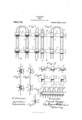
Be it known that I, FRANK MARTIN, a citizen of the United States, residing at Worcester, in the county of WVorcester and Commonwealth of Massachusetts, have invented a new and useful Improvement in Fences, of which the following is a specification accompanied by drawings forming a part of the same, in which Figure 1 is a front view of my improved fence. Fig. 2 is a rear View of the same. Fig. 3 is a section on line 33, Fig. 2. Fig. 4 is a section on line 44, Fig. 2. Fig. 5 is a horizontal section just above one rail of the fence. Fig. 6 is a rear view of the rail before the pickets are inserted. Fig. 7 is a perspective view of a modified form of my improved fence. Fig. 8 is an end view of the same.
Similar reference figures refer to similar parts in the different views.
My invention relates to improvements in metal fences made of upright wires connected by horizontal metal rails, and it consists in the construction and arrangement of parts as hereinafter described and pointed out in the annexed claims.
Referring to the accompanying drawings 1 denotes a series of individual pickets, preferably constructed of wire, and, in this instance, joined in pairs by semicircular extensions at the top.
Connecting the individual pickets is a rail 2 constructed of a strip of band iron or similar fiat material, as shown in Figs. 5 and 6. At convenient intervals for the attachment of the pickets to the rail, restricted flanges or wings 3 extend on either side, and a depression or pocket 4, preferably semicylindrical in shape, and arranged with its axis parallel to the rail, is formed in the rail and between each pair of wings 3. The form of the pocket 4 may, however, be varied as desired, all that is necessary being to form opposite sides 5 and 6 approximately at right angles to the plane of the rail 2, to support the pickets. The pockets 4 are connected by plane pieces 7 of the metal strip from which the rail is constructed, so that it is possible to bend the rail after the pickets are attached, when desired, and so coil the fence.
Openings 8 are constructed on opposite sides of the pockets 4 to permit the passage of the wire picket 1. After the picket and Specification of Letters Patent.
Application filed February 26, 1908.
Patented Sept. 6, 1910.
Serial No. 417,895.
rails are thus assembled, the wings 3 are folded upon the opening 9 constituting the entrance to the pocket 4. The wings 3 are arranged to be bent downward into the pocket 4, thereby also bending the picket 1 at the point where it passes through the pocket 4, see Fig. 3. The rail 2 and picket 1 are thereby held from movement with relation to each other, and the construction of the fence is complete. The final position of the wings 3 is arranged to close the entrance to the pocket 4, thereby preventing the admission of dirt or foreign matter to the pocket 4.
The fence may be erected by inserting the ends 10 of the pickets 1 into the ground, or by attaching the rails to corner posts in any desired manner.
Figs. 7 and 8 show a modified form of fence in which the entire rail is semi-cylindrical in form, inclosing a continuous space parallel with the axis of the rail, with transverse pickets at suitable intervals passing in the same manner through the continuous space inolosed by the rail as through the separate pockets 4. The space inolosed by the rail is closed by longitudinal flanges 11, 11, bent inward similarly to the wings 3, thereby also bending the pickets at their point of passage through the inolosed space, as shown in Fig. 8.
I claim:
1. A fence, comprising a series of longitudinal and a series of transverse members, with a portion of each member of one series arranged to be hollow, inclosing a space parallel with the axis of said member, with a member of the other series passing through said space, and with one side of each hollow member bent inward, thereby imparting a -bend to the member of the other series as it passes through said space.
2. A fence, having a rail, with a portion of said rail hollow, inclosing a space parallel with the axis of the rail, a transverse picket passing through said space, with one side of the hollow portion of said rail bent inward to impart a bend to said picket as it passes through said space.
3. A fence, having a rail inclosing a space parallel with the axis of the rail, said space open on one side, a transverse picket passing through said space, and flanges or wings adjoining the open side of said space and arranged to be folded into said space and impart a bend to the picket as it passes through said space.
4:. A fence, having a transversely bendable rail with successive pockets, each pocket inclosing a space parallel with the axis of the rail, a transverse picket passing through each space, and with one side of each pocket bent inward to impart a bend to the picket as it passes through said space.
5. A fence, having a transversely bendable rail with successive depressions with parallel sides at right angles to the plane of said rail, each pair of said sides having opposite openings to receive a transverse picket.
6. A fence, having a transversely bendable rail with a series of depressions, each inclosing a semi-cylindrical space, with the axis of each space parallel to the axis of said rail, a transverse picket passing diametrically through each space, with flanges or wings adjoining each depression and arranged to be bent into said space to impart a bend to the picket as it passes through said space.
7. A fence, having a rail comprising a metal strip having successive depressions with parallel sides at right angles to the plane of said strip, a transverse picket passing through the sides of each depression, and a pair of wings on said strip corresponding to each depression, arranged to be bent between said sides and to impart a bend to said picket between said sides.
8. A fence, having a transversely bendable rail, with successive portions of said rail hollow, inclosing interrupted spaces open on one side and parallel with the axis of the rail, a transverse picket passing through each space, and means for closing the open side of each hollow portion.
9. A fence, having a rail formed from a metal strip with a series of longitudinal depressions in said strip, said depressions having parallel sides with opposite openings, and transverse pickets inserted in said opposite openings.
Dated this seventeenth day of February 1908.
FRANK MARTIN.
Vitnesses:
LAWRENCE P. GREENMAN, FRANK E. lVLE'rcALF.
Priority Applications (1)
| Application Number | Priority Date | Filing Date | Title |
|---|---|---|---|
| US41789508A US969175A (en) | 1908-02-26 | 1908-02-26 | Fence. |
Applications Claiming Priority (1)
| Application Number | Priority Date | Filing Date | Title |
|---|---|---|---|
| US41789508A US969175A (en) | 1908-02-26 | 1908-02-26 | Fence. |
Publications (1)
| Publication Number | Publication Date |
|---|---|
| US969175A true US969175A (en) | 1910-09-06 |
Family
ID=3037565
Family Applications (1)
| Application Number | Title | Priority Date | Filing Date |
|---|---|---|---|
| US41789508A Expired - Lifetime US969175A (en) | 1908-02-26 | 1908-02-26 | Fence. |
Country Status (1)
| Country | Link |
|---|---|
| US (1) | US969175A (en) |
-
1908
- 1908-02-26 US US41789508A patent/US969175A/en not_active Expired - Lifetime
Similar Documents
| Publication | Publication Date | Title |
|---|---|---|
| US328392A (en) | Panel picket fence | |
| US207518A (en) | Improvement in fences | |
| US1002641A (en) | Toy fence. | |
| US1250617A (en) | Fence-post. | |
| US220392A (en) | Improvement in iron fences | |
| US606461A (en) | Wire-fence clamp | |
| US1144288A (en) | Fence-post. | |
| US836281A (en) | Fence-post. | |
| US479050A (en) | Albert l | |
| US372060A (en) | Wire fence | |
| US773624A (en) | Wire-fence-stay fastener. | |
| US335298A (en) | William h | |
| US579950A (en) | Fence | |
| US567960A (en) | Stay for wire fencing | |
| US1250184A (en) | Wire fence. | |
| US197661A (en) | Improvement in wire fences | |
| US367398A (en) | Barbed fence | |
| US401244A (en) | Splicing device | |
| US738477A (en) | Weeder-tooth. | |
| US381942A (en) | Fence | |
| US992872A (en) | Metallic post. | |
| US522818A (en) | Metallic fence-post | |
| US275607A (en) | Support and guard for wire fences | |
| US828429A (en) | Cement fence-post. | |
| US970595A (en) | Wire mat. |