US9669478B2 - Milling tool - Google Patents
Milling tool Download PDFInfo
- Publication number
- US9669478B2 US9669478B2 US14/769,732 US201414769732A US9669478B2 US 9669478 B2 US9669478 B2 US 9669478B2 US 201414769732 A US201414769732 A US 201414769732A US 9669478 B2 US9669478 B2 US 9669478B2
- Authority
- US
- United States
- Prior art keywords
- cutting head
- faces
- clamping
- longitudinal axis
- tool shank
- Prior art date
- Legal status (The legal status is an assumption and is not a legal conclusion. Google has not performed a legal analysis and makes no representation as to the accuracy of the status listed.)
- Active
Links
- 238000003801 milling Methods 0.000 title claims abstract description 54
- 238000005520 cutting process Methods 0.000 claims abstract description 164
- 239000000463 material Substances 0.000 claims description 17
- 238000003754 machining Methods 0.000 claims description 8
- 238000000034 method Methods 0.000 claims description 8
- 239000002184 metal Substances 0.000 claims description 5
- 239000011195 cermet Substances 0.000 claims description 3
- 238000011161 development Methods 0.000 description 16
- 230000018109 developmental process Effects 0.000 description 16
- 238000004519 manufacturing process Methods 0.000 description 9
- 239000000843 powder Substances 0.000 description 6
- 230000000694 effects Effects 0.000 description 5
- 230000007704 transition Effects 0.000 description 5
- 238000003825 pressing Methods 0.000 description 3
- 238000005245 sintering Methods 0.000 description 3
- 229910001315 Tool steel Inorganic materials 0.000 description 2
- 230000005540 biological transmission Effects 0.000 description 2
- 230000001419 dependent effect Effects 0.000 description 2
- 230000003993 interaction Effects 0.000 description 2
- 229910052582 BN Inorganic materials 0.000 description 1
- PZNSFCLAULLKQX-UHFFFAOYSA-N Boron nitride Chemical compound N#B PZNSFCLAULLKQX-UHFFFAOYSA-N 0.000 description 1
- 241000219793 Trifolium Species 0.000 description 1
- 230000015572 biosynthetic process Effects 0.000 description 1
- 238000010276 construction Methods 0.000 description 1
- 229910003460 diamond Inorganic materials 0.000 description 1
- 239000010432 diamond Substances 0.000 description 1
- 238000000227 grinding Methods 0.000 description 1
- 238000012423 maintenance Methods 0.000 description 1
- 239000007769 metal material Substances 0.000 description 1
- 239000007858 starting material Substances 0.000 description 1
- 230000003313 weakening effect Effects 0.000 description 1
Images


Classifications
-
- B—PERFORMING OPERATIONS; TRANSPORTING
- B23—MACHINE TOOLS; METAL-WORKING NOT OTHERWISE PROVIDED FOR
- B23C—MILLING
- B23C5/00—Milling-cutters
- B23C5/02—Milling-cutters characterised by the shape of the cutter
- B23C5/10—Shank-type cutters, i.e. with an integral shaft
-
- B—PERFORMING OPERATIONS; TRANSPORTING
- B23—MACHINE TOOLS; METAL-WORKING NOT OTHERWISE PROVIDED FOR
- B23B—TURNING; BORING
- B23B31/00—Chucks; Expansion mandrels; Adaptations thereof for remote control
- B23B31/005—Cylindrical shanks of tools
-
- B—PERFORMING OPERATIONS; TRANSPORTING
- B23—MACHINE TOOLS; METAL-WORKING NOT OTHERWISE PROVIDED FOR
- B23B—TURNING; BORING
- B23B31/00—Chucks; Expansion mandrels; Adaptations thereof for remote control
- B23B31/02—Chucks
- B23B31/10—Chucks characterised by the retaining or gripping devices or their immediate operating means
- B23B31/11—Retention by threaded connection
-
- B—PERFORMING OPERATIONS; TRANSPORTING
- B23—MACHINE TOOLS; METAL-WORKING NOT OTHERWISE PROVIDED FOR
- B23B—TURNING; BORING
- B23B2231/00—Details of chucks, toolholder shanks or tool shanks
- B23B2231/02—Features of shanks of tools not relating to the operation performed by the tool
- B23B2231/0204—Connection of shanks to working elements of tools
-
- B—PERFORMING OPERATIONS; TRANSPORTING
- B23—MACHINE TOOLS; METAL-WORKING NOT OTHERWISE PROVIDED FOR
- B23B—TURNING; BORING
- B23B2240/00—Details of connections of tools or workpieces
- B23B2240/32—Press fits
-
- B—PERFORMING OPERATIONS; TRANSPORTING
- B23—MACHINE TOOLS; METAL-WORKING NOT OTHERWISE PROVIDED FOR
- B23B—TURNING; BORING
- B23B2251/00—Details of tools for drilling machines
- B23B2251/02—Connections between shanks and removable cutting heads
-
- B—PERFORMING OPERATIONS; TRANSPORTING
- B23—MACHINE TOOLS; METAL-WORKING NOT OTHERWISE PROVIDED FOR
- B23C—MILLING
- B23C2210/00—Details of milling cutters
- B23C2210/02—Connections between the shanks and detachable cutting heads
-
- B—PERFORMING OPERATIONS; TRANSPORTING
- B23—MACHINE TOOLS; METAL-WORKING NOT OTHERWISE PROVIDED FOR
- B23C—MILLING
- B23C2210/00—Details of milling cutters
- B23C2210/03—Cutting heads comprised of different material than the shank irrespective of whether the head is detachable from the shank
-
- B—PERFORMING OPERATIONS; TRANSPORTING
- B23—MACHINE TOOLS; METAL-WORKING NOT OTHERWISE PROVIDED FOR
- B23C—MILLING
- B23C2240/00—Details of connections of tools or workpieces
- B23C2240/24—Connections using screws
Definitions
- the present invention relates to a milling tool having a tool shank and a cutting head fastened to the front side of the tool shank, to a cutting head for such a milling tool, to the use of such a cutting head, and to a method for fastening a cutting head to a tool shank of a milling tool.
- Hard materials that are used, in addition to hard metal and cermets, include ultrahard materials such as, in particular, polycrystalline diamond (PCD) or cubic boron nitride (CBN).
- PCD polycrystalline diamond
- CBN cubic boron nitride
- a tool shank which may be manufactured from a tougher and more cost-effective material, for example tool steel, with exchangeable components made of hard material, which are provided with the cutting edges.
- milling tools are in this case frequently formed with a tool shank made for example of tool steel, which is equipped with a plurality of indexable cutting inserts which may each have a plurality of cutting edges which can be brought successively into use by indexing in the event of wear occurring.
- a tool shank made for example of tool steel
- indexable cutting inserts which may each have a plurality of cutting edges which can be brought successively into use by indexing in the event of wear occurring.
- DE 203 06 151U1 discloses a milling tool which has a tool shank to the front side of which an exchangeable cutting head is fastened, said cutting head being provided with a plurality of cutting edges.
- the tool shank has a front-side recess into which a protrusion on the underside of the cutting head, which has exactly the shape of the recess, is introduced in a form-fitting manner in the axial direction.
- this configuration requires the maintenance of extremely tight tolerances for the protrusion on the underside of the cutting head.
- the milling tool has a tool shank with a longitudinal axis and a cutting head fastened to the front side of the tool shank, said cutting head having a plurality of cutting edges for machining a workpiece.
- the tool shank and the cutting head are connected together via a clamping connection.
- the clamping connection has a protrusion circumferentially having a plurality of clamping faces, and a recess circumferentially having a plurality of centering faces that interact with the clamping faces.
- the centering faces each have a first region in which the centering faces are at a first distance from the longitudinal axis in a section perpendicular to the longitudinal axis, and the first region transitions into a second region in which the centering faces are at a smaller second distance from the longitudinal axis in the section perpendicular to the longitudinal axis, such that the clamping faces of the protrusion are introducible into the recess between the first regions of the centering faces and are movable, by rotation of the cutting head about the longitudinal axis relative to the tool shank, into a clamping position in which the clamping faces interact in a force-fitting manner with the second regions of the centering faces.
- the protrusion of the clamping connection can in this case, according to a preferred first variant, be formed on the cutting head and the recess in the tool shank. According to a second variant, however, the recess of the clamping connection can also be formed in the cutting head and the protrusion on the tool shank.
- the forces that act on a fastening screw in order to fasten the cutting head to the tool shank are kept very low, with the result that the reliability of the milling tool is increased.
- the contact regions, effecting the force fit, of the clamping faces with the centering faces it is advantageously possible for the contact regions, effecting the force fit, of the clamping faces with the centering faces to extend at least substantially tangentially in a circle, the center of which is located on the longitudinal axis of the milling tool.
- the forces effecting the force fit flow in this case substantially in a radial direction.
- substantially tangential is understood to mean in this case a deviation from the tangential direction of less than 10°, preferably less than 8°, more preferably less than 5°.
- axial, radial or tangential, or forms derived therefrom are used in the context of the present description, these terms relate in each case to the longitudinal axis of the milling tool, said axis at the same time forming the rotation axis during operation of the milling tool.
- the recess has a plurality of radially inwardly projecting stop portions which limit a rotation of the cutting head about the longitudinal axis relative to the tool shank.
- the stop portions serve at the same time as entrainment portions which facilitate reliable transmission of the rotation from the tool shank to the cutting head.
- the clamping faces extend in a common circle, the center of which is located on the longitudinal axis, when viewed in a section perpendicular to the longitudinal axis.
- the clamping faces extend along a common cylinder or cone surface, the axis of symmetry of which coincides with the longitudinal axis.
- particularly easy manufacture of the clamping faces is allowed.
- particularly easy powder metallurgical manufacture of the clamping faces without mechanical reworking is allowed.
- the protrusion narrows preferably in the direction of its free end.
- the protrusion has three clamping faces.
- reliable centering of the cutting head in and fastening thereof to the tool shank is allowed with tight tolerance specifications.
- the clamping faces are distributed regularly around the outer circumference of the protrusion in this case.
- the clamping faces form the radially furthest protruding regions of the protrusion in a section perpendicular to the longitudinal axis.
- force introduction for the force-fitting connection between the clamping faces and the centering faces is reliably achieved, with the acting forces flowing substantially in the radial direction.
- the cutting head has a bore for receiving a fastening screw, and the bore extends in the axial direction through the cutting head. In this case, particularly reliable and symmetrical fastening of the cutting head to the tool shank is achieved.
- a coaxial threaded bore for fastening the cutting head to the tool shank is formed in the tool shank.
- a threaded bush which has an external thread for interacting with the threaded bore in the tool shank, and an internal thread for interacting with a fastening screw for fastening the cutting head.
- the threaded bush allows reliable releasing of the cutting head from the tool shank when the cutting head is intended to be exchanged.
- the threaded bush has an outside diameter, at least on a side facing the cutting head, which is greater than an inside diameter of a bore in the cutting head.
- the force-fitting connection between the cutting head and the tool shank can be released particularly reliably in that that side of the threaded bush that faces the cutting head is pressed against the cutting head.
- the threaded bush is provided on a side facing the cutting head with a profile for engagement by a screwdriving tool, such that the threaded bush can be moved easily in order to release the force-fitting connections between the cutting head and the tool shank.
- the profile can be formed in this case for example by an internal profile, such as in particular a hexagon socket.
- the cutting head has a bore for receiving a fastening screw, the diameter of said bore being coordinated with the profile for engagement by a screwdriving tool such that a screwdriving tool is able to be brought into engagement with the profile through the bore in the cutting head.
- a screwdriving tool is able to be brought into engagement with the profile through the bore in the cutting head.
- particularly convenient exchange of the cutting head is allowed.
- at least parts of the profile can have an inside diameter which is smaller than the diameter of the bore in order to receive the fastening screw.
- the protrusion of the clamping connection is formed integrally with the cutting head and the recess of the clamping connection is formed in the front side of the tool shank.
- the protrusion that is under pressure in the clamping position is formed from the usually more brittle material of the cutting head and the recess is formed from the tougher material of the tool shank, such that undesired splitting of the material of the cutting head can be reliably prevented.
- the protrusion is formed with the rest of the cutting head in a common powder metallurgical production process, such that the protrusion and the rest of the cutting head have a substantially homogeneous microstructure.
- the protrusion of the clamping connection is formed integrally with the tool shank and the recess of the clamping connection is formed in the cutting head.
- the cutting head is formed from a hard material, in particular hard metal or a cermet.
- the cutting head for an above-described milling tool has a plurality of cutting edges for machining a workpiece, and a protrusion, formed integrally with the cutting head, having a plurality of clamping faces for the simultaneous clamping and centering of the cutting head in a recess in a tool shank.
- the clamping faces are configured to form a force-fitting connection with centering faces in the recess.
- the clamping faces extend along the contour of a common circle, the center of which is located on the longitudinal axis, in a section perpendicular to a longitudinal axis of the cutting head.
- the advantages specified above with regard to the milling tool are achieved.
- the arrangement of the clamping faces such that these extend along the contour of the common circle in particular a self-centering and reliable connection to the tool shank is achieved, said connection not requiring any reworking of the protrusion on the cutting head.
- forces acting on a fastening screw for fastening the cutting head to the tool shank are kept very low.
- the contact regions, effecting the force fit, of the clamping faces with the centering faces extend at least substantially tangentially in a circle, the center of which is located on the longitudinal axis.
- the protrusion has flattened portions, arranged between adjacent clamping faces, for support against radially inwardly protruding stop portions in a recess in a tool shank.
- the clamping position of the cutting head in the recess can be determined exactly, and the clamping forces acting in the radial direction, which effect the force fit between the cutting head and the tool shank, can be limited reliably, such that an undesirably high application of force on the walls of the recess is prevented.
- reliable transmission of the rotation from the tool shank to the cutting head is allowed during operation of the milling tool.
- the clamping faces form the radially furthest protruding regions of the protrusion in a section perpendicular to the longitudinal axis.
- force introduction for the force-fitting connection between the clamping faces and centering faces provided on a recess is reliably achieved, with the acting forces flowing substantially in a radial direction.
- the clamping faces extend along the contour of a common cylinder or cone surface, the axis of symmetry of which coincides with the longitudinal axis.
- particularly easy manufacture of the clamping faces is allowed, in particular powder metallurgical manufacture of the clamping faces without mechanical reworking.
- the centering faces each have a first region in which the centering faces are at a first distance from the longitudinal axis in a section perpendicular to the longitudinal axis, and the first region transitions into a second region in which the centering faces are at a smaller second distance from the longitudinal axis in the section perpendicular to the longitudinal axis.
- the clamping faces are brought into a force-fitting connection with the second regions of the centering faces.
- the object is also achieved by a method for fastening a cutting head to a tool shank as claimed.
- the method has the following steps: introduction of the clamping faces of the protrusion between the first regions of the centering faces and into the recess, and rotation of the cutting head about the longitudinal axis relative to the tool shank and into a clamping position such that the clamping faces pass into a force-fitting connection with the second regions of the centering faces.
- FIG. 1 shows a perspective illustration of a milling tool according to one embodiment
- FIG. 2 shows a side view of the milling tool according to the embodiment
- FIG. 3 shows a sectional illustration along the line A-A in FIG. 2 ;
- FIG. 4 shows a sectional illustration corresponding to FIG. 3 but without a fastening screw
- FIG. 5 shows a perspective illustration of the threaded bush in the embodiment
- FIG. 6 shows a schematic basic illustration to explain the clamping connection in the embodiment
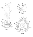
- FIG. 7 shows a perspective illustration of the tool shank in the embodiment
- FIG. 8 shows a sectional illustration of the tool shank
- FIG. 9 shows a perspective illustration of a cutting head in the embodiment
- FIG. 10 shows a further perspective illustration of the cutting head
- FIG. 11 shows a plan view of the front side of the cutting head
- FIG. 12 shows a plan view of the rear side of the cutting head
- FIG. 13 shows a section perpendicular to the longitudinal axis in the region of a protrusion and of a recess of a clamping connection in a first position
- FIG. 14 shows a section perpendicular to the longitudinal axis in the region of the protrusion and of the recess in a second position
- FIG. 15 shows a basic illustration corresponding to FIG. 11 to explain the clamping connection between the cutting head and the tool shank;
- FIG. 16 shows a basic illustration corresponding to FIG. 12 to explain the clamping connection.
- a milling tool 1 according to one embodiment of the present invention is described in the following text with reference to FIGS. 1 to 16 .
- the milling tool 1 has a tool shank 2 , which is configured to be fastened by way of a rear end 2 a to a corresponding receptacle in a milling machine.
- the tool shank 2 has a longitudinal axis L, which simultaneously forms the rotation axis of the milling tool 1 during operation of the milling tool 1 in a milling machine.
- the tool shank 2 has substantially a cylindrical basic shape, wherein, in the exemplary embodiment illustrated, the outside diameter at a front end 2 b opposite the rear end 2 a is somewhat smaller than at the rear end 2 a.
- the tool shank 2 has on its outer circumference a notch 2 c for fastening to the receptacle of the milling machine in a rotationally locked manner.
- a recess 3 Formed at the front end 2 b of the tool shank 2 is a recess 3 , which will be described in more detail in the following text.
- the recess 3 is configured such that a cutting head is fastenable to the front side of the tool shank 2 .
- the recess 3 is surrounded at the front end 2 b by a flat abutment face 2 d , which extends perpendicularly to the longitudinal axis L of the tool shank 2 and forms a large support for the cutting head 4 fastened to the tool shank 2 .
- the recess 3 has, next to the free end, a first portion 3 a having a relatively large cross section.
- the first portion 3 a is adjoined, via a shoulder 3 b , by a substantially cylindrical second portion 3 c having a smaller cross section, which is adjoined, via a further shoulder, by a threaded bore 5 coaxial with the longitudinal axis L.
- the threaded bore 5 is embodied as a blind hole, which is provided with an internal thread, the function of which will be described in more detail. In the direction perpendicular to the longitudinal axis L, the threaded bore 5 has a cross section which is smaller than the cross section of the first portion 3 a of the recess 3 .
- the shape of the first portion 3 a of the recess 3 will be explained in more detail with reference to FIG. 6 and FIG. 7 .
- the first portion 3 a has, in the plane perpendicular to the longitudinal axis L, a shape which is similar to a stylized three-leaf clover.
- the side walls of the recess 3 are formed in the first portion 3 a by three centering faces 6 , between which radially inwardly protruding stop portions 7 are formed.
- the first portion 3 a has three-fold rotational symmetry with respect to the longitudinal axis L.
- the centering faces 6 are formed in a concave manner.
- the stop portions 7 are formed in a convex manner in a section perpendicular to the longitudinal axis L, such that they form radially inwardly protruding protrusions.
- the centering faces 6 and the stop portions 7 extend in each case at least substantially parallel to the longitudinal axis L. According to one development, however, it is for example also possible for the internal cross section of the first portion 3 a to narrow in the direction from the front end 2 b to the rear end 2 a of the tool shank 2 .
- the centering face 6 have, in a section perpendicular to the longitudinal axis L, a first region 6 a , in which the centering faces 6 are at a first distance from the longitudinal axis L.
- the first region 6 a transitions continuously into a second region 6 b , in which the centering faces 6 are at a smaller, second distance from the longitudinal axis L.
- the surfaces of the centering faces 6 approach the longitudinal axis L with continued progress around the longitudinal axis L.
- the centering faces 6 are oriented such that, with a viewing direction toward the front end 2 b of the tool shank 2 , they approach the longitudinal axis L with continued progress in the clockwise direction around the longitudinal axis L.
- the centering faces 6 it is for example also possible to configure the centering faces 6 such that they approach the longitudinal axis L with continued progress in the counterclockwise direction.
- the centering faces 6 have in this case a concavely curved shape.
- the centering faces 6 can for example preferably have a cylindrically or elliptically curved shape, such that they approach the longitudinal axis L as uniformly as possible with continued rotation.
- a threaded bush 8 which is received at least partially in the threaded bore 5 .
- the threaded bush 8 has a threaded portion 8 a , which is provided at least regionally with an external thread 8 c , which is intended to interact with the internal thread of the threaded bore 5 .
- the threaded bush 8 also has a head portion 8 b . In the embodiment illustrated, the head portion 8 b has a somewhat larger external circumference than the threaded portion 8 a .
- the head portion 8 b is dimensioned such that, when the threaded portion 8 a is screwed into the threaded bore 5 , it can be received in the second portion 3 c of the recess 3 .
- the threaded bush 8 has, at least in the head portion 8 b , an outside diameter which is larger than the diameter of a bore 10 in the cutting head 4 , as will be described in more detail.
- the front side 8 f of the head portion 8 b has a face which is configured to press against an underside of the cutting head 4 .
- the threaded bush 8 is furthermore provided at least regionally with an internal thread 8 d , which is configured to interact with an external thread of a fastening screw 9 in order to fasten the cutting head 4 to the tool shank 2 .
- the threaded bush 8 is furthermore provided on its inner side with a profile 8 e for engagement by a screwdriving tool.
- the profile 8 e for engagement by a screwdriving tool is configured for example as a hexagon socket.
- some other shape, which allows interaction with a corresponding screwdriving tool is also possible.
- the profile 8 e for engagement by a screwdriving tool has a free internal cross section which is somewhat larger than the diameter of the internal thread 8 d .
- the configuration of the cutting head 4 in the present exemplary embodiment will now be described in more detail with reference to FIG. 9 to FIG. 12 .
- the cutting head 4 is configured in the embodiment as an integral component produced from hard metal or cermet in a powder metallurgical production process by pressing and sintering.
- the cutting head 4 is provided with a plurality of cutting edges 4 a for machining a workpiece.
- the cutting head 4 is configured specifically for high-feed milling, as is apparent from the arrangement of the cutting edges 4 a .
- the first portion has at least one abutment face 10 a , against which the underside of the head of the fastening screw 9 is supported in order to clamp the cutting head 4 against the tool shank 2 .
- the first portion has for example a cross section that narrows conically in the direction of the rear side 4 c of the cutting head 4 in order to receive a conical countersunk head of the fastening screw 9 .
- other configurations are for example also possible, such as in particular a stepped configuration in order to receive a flat or cylindrical head of the fastening screw 9 .
- the first portion transitions into a second portion 10 b , which has a smaller diameter with a substantially cylindrical cross section.
- the diameter of the second portion 10 b is dimensioned such that the external thread on a threaded portion of the fastening screw 9 can be guided through the second portion 10 b .
- the diameter of the second portion 10 b is furthermore dimensioned such that it is smaller than the outside diameter of the head portion 8 b of the threaded bush 8 .
- a protrusion 11 is formed on the rear side 4 c of the cutting head 4 .
- the protrusion 11 has a smaller external circumference than the front side 4 b of the cutting head 4 , such that a flat bearing face 4 d is formed on the rear side 4 c of the cutting head 4 , the cutting head 4 being supported on the flat abutment face 2 d of the tool shank 2 by way of said flat bearing face 4 d .
- the bearing face 4 d extends around the protrusion 11 in a plane perpendicular to the longitudinal axis L. In the axial direction, the protrusion 11 has a height which is somewhat smaller than the depth of the first portion 3 a of the recess 3 .
- the bore 10 in particular the second portion 10 b thereof, also extends through the protrusion 11 .
- the protrusion 11 and the recess 3 together form a part of a clamping connection between the cutting head 4 and the tool shank 2 .
- the protrusion 11 and the recess 3 effect clamping in an interacting manner, as will be described in more detail.
- the external contour of the protrusion 11 is described in more detail in the following text with reference to FIG. 6 , FIG. 10 and FIG. 12 .
- the protrusion 11 has a plurality n of clamping faces 12 , which are configured to interact with the centering faces 6 of the recess 3 .
- the clamping faces 12 extend along the contour of a common circle, the center of which is located on the longitudinal axis L, in a section perpendicular to the longitudinal axis L.
- the clamping faces 12 form the radially furthest protruding regions of the protrusion 11 in the section perpendicular to the longitudinal axis L.
- the clamping faces 12 extend along a common cylinder surface, wherein the cylinder axis corresponds to the longitudinal axis L.
- the clamping faces 12 can for example also extend along a common cone surface, wherein the code axis extends along the longitudinal axis L.
- clamping faces 12 which are configured in a relatively extensive manner are illustrated in the exemplary embodiment, said clamping faces having a relatively large extent both in the axial direction and in the tangential direction, the size of the clamping faces 12 can also be reduced without having a significant effect on functioning. In an extreme case, the clamping faces 12 can be reduced to virtually punctiform contact regions with the centering faces 6 .
- the clamping faces 12 are distributed symmetrically around the circumference of the protrusion 11 and flattened portions 13 for support against the radially inwardly protruding stop portions 7 , which are provided in the recess 3 , are arranged between the clamping faces 12 .
- the contour of the protrusion 11 is located completely within the common circle, along which the clamping faces 12 extend, in a section perpendicular to the longitudinal axis L.
- the clamping faces 12 are considerably narrower than the corresponding centering faces 6 , which are formed in the recess 3 .
- the clamping faces 12 are approximately half as wide as the centering faces 6 , as can be seen in FIG.
- the cutting head 4 is formed in a manner free of undercuts, thereby allowing direct powder metallurgical production by pressing and sintering, wherein mechanical reworking by grinding is necessary only in the region of the cutting edges 4 a.
- the distance of the first regions 6 a of the centering faces 6 from the longitudinal axis L is selected such that it is somewhat greater than the distance of the clamping faces 12 from the longitudinal axis L, such that the protrusion 11 can be introduced into the recess 3 in this orientation.
- the cutting head 4 and the tool shank 2 are moved toward one another in the longitudinal direction until the bearing face 4 d of the cutting head 4 is supported against the abutment face 2 d of the tool shank 2 .
- the clamping faces 12 of the protrusion 11 are moved in the tangential direction from the first regions 6 a to the second regions 6 b of the centering faces 6 in the recess 3 , as is illustrated in FIG. 14 and FIG. 16 .
- the clamping faces 12 move along the centering faces 6 .
- the distance of the second regions 6 b of the centering faces 6 from the longitudinal axis L is selected such that it is somewhat smaller than the distance of the clamping faces 12 from the longitudinal axis L.
- the possible rotation of the cutting head 4 relative to the tool shank 2 is limited by the stop portions 6 and the flattened portions 13 , interacting therewith, which prevent further relative movement when the clamping faces 12 are located opposite the second regions 6 b of the centering faces 6 .
- the acting force for the force-fitting connection of the cutting head 4 to the tool shank 2 can be determined reliably via the angle which the centering faces 6 enclose with the clamping faces 12 in their contact region, and by the possible angle of rotation which is given substantially by the width of the clamping faces 12 compared with the width of the centering faces 6 in the tangential direction.
- the angle which the centering faces 6 enclosed with the clamping faces 12 in the contact region can in this case be determined via the extent to which the centering faces 6 approach to the longitudinal axis from the first region 6 a to the second region 6 b .
- a relative rotation of the cutting head 4 through about 35° with respect to the tool shank 2 is allowed.
- a relative rotation through at least 15°, preferably at least 20°, more preferably at least 25° should be allowed.
- the fastening of the cutting head 4 to the tool shank 2 is concluded in that the fastening screw 9 is guided by way of its threaded portion through the bore 10 and is screwed into the internal thread 8 d of the threaded bush 8 until the underside of the head of the fastening screw 9 is supported on the abutment face 10 c of the bore 10 .
- the forces acting on the fastening screw 9 during operation of the milling tool 1 are very low.
- the fastening screw 9 is screwed out of the internal thread 8 d of the threaded bush 8 again and removed from the milling tool 1 .
- a screwdriving tool for example a hexagon screwdriving tool, can be guided through the bore 10 and can be brought into engagement with the profile 8 a for engagement by a screwdriving tool in the threaded bush 8 .
- the protrusion 11 of the clamping connection is formed on the cutting head 4 and the recess 3 is formed on the tool shank 2
- the protrusion 11 is provided on the front side of the tool shank 2 and has, in the same way, the clamping faces 12 and the flattened portions 13
- the recess 3 is formed in the rear side 4 c of the cutting head 4 and has, in the same way, the centering faces 6 and the abutment portions 7 formed between the latter.
- the threaded bush 8 can be provided and arranged in a coaxial bore which extends from the free end into the protrusion 11 .
Landscapes
- Engineering & Computer Science (AREA)
- Mechanical Engineering (AREA)
- Milling Processes (AREA)
Applications Claiming Priority (4)
| Application Number | Priority Date | Filing Date | Title |
|---|---|---|---|
| ATGM60/2013 | 2013-02-22 | ||
| ATGM60/2013U AT13498U1 (de) | 2013-02-22 | 2013-02-22 | Fräswerkzeug |
| AT60/2013 | 2013-02-22 | ||
| PCT/AT2014/000032 WO2014127391A1 (de) | 2013-02-22 | 2014-02-18 | Fräswerkzeug |
Publications (2)
| Publication Number | Publication Date |
|---|---|
| US20150375309A1 US20150375309A1 (en) | 2015-12-31 |
| US9669478B2 true US9669478B2 (en) | 2017-06-06 |
Family
ID=49955562
Family Applications (1)
| Application Number | Title | Priority Date | Filing Date |
|---|---|---|---|
| US14/769,732 Active US9669478B2 (en) | 2013-02-22 | 2014-02-18 | Milling tool |
Country Status (7)
| Country | Link |
|---|---|
| US (1) | US9669478B2 (de) |
| EP (1) | EP2958693B1 (de) |
| CN (1) | CN105142833B (de) |
| AT (1) | AT13498U1 (de) |
| ES (1) | ES2734351T3 (de) |
| PL (1) | PL2958693T3 (de) |
| WO (1) | WO2014127391A1 (de) |
Cited By (2)
| Publication number | Priority date | Publication date | Assignee | Title |
|---|---|---|---|---|
| US20150003922A1 (en) * | 2013-06-26 | 2015-01-01 | Vargus Ltd. | Cutting insert and a tool holder with a seat for cutting insert |
| US20230008503A1 (en) * | 2019-10-31 | 2023-01-12 | Dino Paoli S.R.L. | Socket-shaft connection assembly of pneumatic impact wrench |
Families Citing this family (14)
| Publication number | Priority date | Publication date | Assignee | Title |
|---|---|---|---|---|
| US9089911B2 (en) * | 2013-01-31 | 2015-07-28 | Gil Espinosa | Side milling arbor with quad drive key assist |
| DE202014000866U1 (de) * | 2014-02-03 | 2015-05-06 | Johne & Co. Präzisionswerkzeuge GmbH | Werkzeugkopfelement zum Fertigen eines Werkzeugkopfes, Werkzeugkopf und Werkzeugaufnahmemittel |
| CN107457440A (zh) * | 2016-06-03 | 2017-12-12 | 益壮企业有限公司 | 加工工具的组接结构 |
| US10857641B2 (en) | 2017-08-18 | 2020-12-08 | Rolls-Royce Corporation | Tool for facilitating the machining of recessed inserts |
| DE102018112865B3 (de) * | 2018-05-29 | 2019-10-17 | Hartmetall-Werkzeugfabrik Paul Horn Gmbh | Wälzschälwerkzeug |
| DE102019112547A1 (de) | 2019-05-14 | 2020-11-19 | Felss Systems Gmbh | Bearbeitungseinheit und Bearbeitungsmaschine zur Bearbeitung eines Werkstücks an einer Werkstückwand sowie Verfahren zur Herstellung einer Bearbeitungseinheit der genannten Art |
| CN110102809A (zh) * | 2019-05-31 | 2019-08-09 | 江门市中刀精密科技有限公司 | 一种铣削刀具 |
| JP7568939B2 (ja) * | 2019-08-09 | 2024-10-17 | 株式会社Moldino | ヘッド交換式切削工具、切削ヘッド、および工具本体 |
| DE102019135435A1 (de) * | 2019-12-20 | 2021-06-24 | Hartmetall-Werkzeugfabrik Paul Horn Gmbh | Werkzeug und Verfahren zur spanenden Bearbeitung eines Werkstücks |
| EP3922382A1 (de) * | 2020-06-09 | 2021-12-15 | Euroexport Gb Eood | System zur schnellwechselbefestigung von werkzeugen |
| TWI778459B (zh) * | 2020-11-27 | 2022-09-21 | 張新添 | 組合式倒角刀具 |
| CN113523433A (zh) * | 2021-08-11 | 2021-10-22 | 一汽解放汽车有限公司 | 一种铣铰刀 |
| CN116638361B (zh) * | 2023-05-25 | 2024-09-27 | 江苏苏驭研智能设备有限公司 | 用于电池托盘底面去除飞边的浮动式铣刀 |
| CN118990113A (zh) * | 2024-10-22 | 2024-11-22 | 宁波川景誉机械科技发展有限公司 | 列车轨道修复铣刀、使用方法及其应用 |
Citations (26)
| Publication number | Priority date | Publication date | Assignee | Title |
|---|---|---|---|---|
| US2158120A (en) * | 1936-02-19 | 1939-05-16 | Charles A Hirschberg | Detachable drill bit |
| US2219907A (en) * | 1938-04-11 | 1940-10-29 | Walter F Ross | Tool holder assembly |
| DE1253015B (de) | 1965-04-23 | 1967-10-26 | Koelle Maschb G M B H | Fraesdorn |
| US3566947A (en) * | 1969-04-29 | 1971-03-02 | John A Jukes | Self-locking threaded insert |
| US3711105A (en) | 1970-11-12 | 1973-01-16 | Eltee Inc | Tool holding system |
| US4325665A (en) * | 1979-07-26 | 1982-04-20 | John A. Jukes | Threaded metal insert |
| EP0284745A2 (de) | 1987-03-26 | 1988-10-05 | Gottlieb Gühring Kg | Kupplung zwischen einem Werkzeugkopf und einem Werkzeugträger |
| WO1994023874A1 (de) | 1993-04-14 | 1994-10-27 | Zettl GmbH CNC Präzisions- und Sonderwerkzeuge | Schneidwerkzeug |
| US5542795A (en) | 1995-01-30 | 1996-08-06 | Kennametal Inc. | Plunge and face milling cutter with universal insert seats |
| US5551811A (en) * | 1993-02-18 | 1996-09-03 | Iscar, Ltd. | Tool assembly having interfitting male and female coupling members |
| DE19600239C1 (de) | 1996-01-05 | 1997-04-10 | Ima Maschinenfabriken Klessmann Gmbh | Bearbeitungsaggregat für Werkstücke aus Holz und/oder Holzaustauschstoffen |
| US6276879B1 (en) * | 1998-08-13 | 2001-08-21 | Iscar Ltd. | Cutting head for mounting on a tool holder in a self-clamping manner |
| US20020053266A1 (en) * | 2000-06-27 | 2002-05-09 | Lars-Erik Enquist | Positional adjusting mechanism for a cutting insert |
| WO2003101650A1 (en) | 2002-06-04 | 2003-12-11 | Iscar Ltd. | Rotary cutting tool |
| DE20306151U1 (de) | 2003-04-16 | 2004-06-03 | Pokolm, Franz-Josef | Konturfräser |
| DE10255270A1 (de) | 2002-11-21 | 2004-06-03 | Vargus Ltd. | Werkzeug und Verfahren zur Maschinenbearbeitung von Werkstücken |
| CN1610590A (zh) | 2002-01-29 | 2005-04-27 | 山特维克公司 | 用于旋转刀具的刀具连接器 |
| CN1620351A (zh) | 2002-02-15 | 2005-05-25 | 迪哈特股份公司 | 机用铰刀 |
| DE202006014812U1 (de) | 2006-09-27 | 2006-12-07 | Reiner Quanz Gmbh & Co. Kg | Werkzeug-Aufnahme zum Antrieb eines rotierenden Werkzeuges |
| US20070081872A1 (en) | 2005-10-05 | 2007-04-12 | Sandvik Intellectual Property Ab | Milling cutter head and a milling cutter tool |
| US20070220731A1 (en) * | 2006-03-23 | 2007-09-27 | Hardinge, Inc. | Apparatus and method for engaging components through thermal contraction |
| DE202008014738U1 (de) | 2008-11-06 | 2009-01-15 | Reiner Quanz Gmbh & Co. Kg | Antriebskupplung sowie Aufnahmeteil und Spannteil für Rotationsantriebe |
| US7775751B2 (en) * | 2005-11-06 | 2010-08-17 | Iscar, Ltd. | Rotary cutting tool |
| US20120039676A1 (en) * | 2010-08-16 | 2012-02-16 | Iscar, Ltd. | T-Slot Cutter Having Separate Centering and Torque-Transmitting Portions |
| US20120099938A1 (en) | 2010-01-26 | 2012-04-26 | Iscar Ltd. | Cutting Tool and Coupling Mechanism Therefor |
| DE102012212146A1 (de) | 2012-07-11 | 2014-01-16 | Kennametal Inc. | Kupplungsstelle für ein modulares Rotationswerkzeug sowie Werkzeugkopf und Träger für ein solches modulares Rotationswerkzeug |
-
2013
- 2013-02-22 AT ATGM60/2013U patent/AT13498U1/de not_active IP Right Cessation
-
2014
- 2014-02-18 CN CN201480010037.0A patent/CN105142833B/zh active Active
- 2014-02-18 EP EP14717971.7A patent/EP2958693B1/de active Active
- 2014-02-18 US US14/769,732 patent/US9669478B2/en active Active
- 2014-02-18 WO PCT/AT2014/000032 patent/WO2014127391A1/de not_active Ceased
- 2014-02-18 PL PL14717971T patent/PL2958693T3/pl unknown
- 2014-02-18 ES ES14717971T patent/ES2734351T3/es active Active
Patent Citations (34)
| Publication number | Priority date | Publication date | Assignee | Title |
|---|---|---|---|---|
| US2158120A (en) * | 1936-02-19 | 1939-05-16 | Charles A Hirschberg | Detachable drill bit |
| US2219907A (en) * | 1938-04-11 | 1940-10-29 | Walter F Ross | Tool holder assembly |
| DE1253015B (de) | 1965-04-23 | 1967-10-26 | Koelle Maschb G M B H | Fraesdorn |
| US3566947A (en) * | 1969-04-29 | 1971-03-02 | John A Jukes | Self-locking threaded insert |
| US3711105A (en) | 1970-11-12 | 1973-01-16 | Eltee Inc | Tool holding system |
| US4325665A (en) * | 1979-07-26 | 1982-04-20 | John A. Jukes | Threaded metal insert |
| EP0284745A2 (de) | 1987-03-26 | 1988-10-05 | Gottlieb Gühring Kg | Kupplung zwischen einem Werkzeugkopf und einem Werkzeugträger |
| US4856944A (en) | 1987-03-26 | 1989-08-15 | Gottlieb Guhring Kg | Coupling between a tool head and a tool support |
| US5551811A (en) * | 1993-02-18 | 1996-09-03 | Iscar, Ltd. | Tool assembly having interfitting male and female coupling members |
| WO1994023874A1 (de) | 1993-04-14 | 1994-10-27 | Zettl GmbH CNC Präzisions- und Sonderwerkzeuge | Schneidwerkzeug |
| US5607263A (en) | 1993-04-14 | 1997-03-04 | Zettl Gmbh Cnc Prazisions-Und Sonderwerkzuege | Cutting tool |
| US5542795A (en) | 1995-01-30 | 1996-08-06 | Kennametal Inc. | Plunge and face milling cutter with universal insert seats |
| CN1174529A (zh) | 1995-01-30 | 1998-02-25 | 钴碳化钨硬质合金公司 | 带有万能刀片座的插铣和面铣铣刀 |
| DE19600239C1 (de) | 1996-01-05 | 1997-04-10 | Ima Maschinenfabriken Klessmann Gmbh | Bearbeitungsaggregat für Werkstücke aus Holz und/oder Holzaustauschstoffen |
| US6276879B1 (en) * | 1998-08-13 | 2001-08-21 | Iscar Ltd. | Cutting head for mounting on a tool holder in a self-clamping manner |
| US20020053266A1 (en) * | 2000-06-27 | 2002-05-09 | Lars-Erik Enquist | Positional adjusting mechanism for a cutting insert |
| US7189039B2 (en) | 2002-01-29 | 2007-03-13 | Sandvik Intellectual Property Ab | Tool coupling for rotating tools |
| CN1610590A (zh) | 2002-01-29 | 2005-04-27 | 山特维克公司 | 用于旋转刀具的刀具连接器 |
| CN1620351A (zh) | 2002-02-15 | 2005-05-25 | 迪哈特股份公司 | 机用铰刀 |
| US20050220551A1 (en) | 2002-02-15 | 2005-10-06 | Otto Buettiker | Machine reamer |
| US7431543B2 (en) | 2002-02-15 | 2008-10-07 | Dihart Ag | Machine reamer |
| US7004692B2 (en) | 2002-06-04 | 2006-02-28 | Iscar Ltd. | Rotary cutting tool |
| WO2003101650A1 (en) | 2002-06-04 | 2003-12-11 | Iscar Ltd. | Rotary cutting tool |
| DE10255270A1 (de) | 2002-11-21 | 2004-06-03 | Vargus Ltd. | Werkzeug und Verfahren zur Maschinenbearbeitung von Werkstücken |
| DE20306151U1 (de) | 2003-04-16 | 2004-06-03 | Pokolm, Franz-Josef | Konturfräser |
| US20070081872A1 (en) | 2005-10-05 | 2007-04-12 | Sandvik Intellectual Property Ab | Milling cutter head and a milling cutter tool |
| US7775751B2 (en) * | 2005-11-06 | 2010-08-17 | Iscar, Ltd. | Rotary cutting tool |
| US20070220731A1 (en) * | 2006-03-23 | 2007-09-27 | Hardinge, Inc. | Apparatus and method for engaging components through thermal contraction |
| DE202006014812U1 (de) | 2006-09-27 | 2006-12-07 | Reiner Quanz Gmbh & Co. Kg | Werkzeug-Aufnahme zum Antrieb eines rotierenden Werkzeuges |
| DE202008014738U1 (de) | 2008-11-06 | 2009-01-15 | Reiner Quanz Gmbh & Co. Kg | Antriebskupplung sowie Aufnahmeteil und Spannteil für Rotationsantriebe |
| US20120099938A1 (en) | 2010-01-26 | 2012-04-26 | Iscar Ltd. | Cutting Tool and Coupling Mechanism Therefor |
| US20120039676A1 (en) * | 2010-08-16 | 2012-02-16 | Iscar, Ltd. | T-Slot Cutter Having Separate Centering and Torque-Transmitting Portions |
| DE102012212146A1 (de) | 2012-07-11 | 2014-01-16 | Kennametal Inc. | Kupplungsstelle für ein modulares Rotationswerkzeug sowie Werkzeugkopf und Träger für ein solches modulares Rotationswerkzeug |
| US20140017022A1 (en) | 2012-07-11 | 2014-01-16 | Kennametal, Inc. | Coupling point for a modular rotary tool and tool head carrier for a modular rotary tool |
Cited By (3)
| Publication number | Priority date | Publication date | Assignee | Title |
|---|---|---|---|---|
| US20150003922A1 (en) * | 2013-06-26 | 2015-01-01 | Vargus Ltd. | Cutting insert and a tool holder with a seat for cutting insert |
| US9919366B2 (en) * | 2013-06-26 | 2018-03-20 | Vargus Ltd. | Cutting insert and a tool holder with a seat for cutting insert |
| US20230008503A1 (en) * | 2019-10-31 | 2023-01-12 | Dino Paoli S.R.L. | Socket-shaft connection assembly of pneumatic impact wrench |
Also Published As
| Publication number | Publication date |
|---|---|
| ES2734351T3 (es) | 2019-12-05 |
| EP2958693A1 (de) | 2015-12-30 |
| EP2958693B1 (de) | 2019-05-08 |
| AT13498U1 (de) | 2014-01-15 |
| US20150375309A1 (en) | 2015-12-31 |
| WO2014127391A1 (de) | 2014-08-28 |
| CN105142833A (zh) | 2015-12-09 |
| CN105142833B (zh) | 2017-10-27 |
| WO2014127391A8 (de) | 2015-09-17 |
| PL2958693T3 (pl) | 2019-11-29 |
Similar Documents
| Publication | Publication Date | Title |
|---|---|---|
| US9669478B2 (en) | Milling tool | |
| JP5839435B2 (ja) | コレットホルダを有する工具ホルダおよび工具ホルダで用いる工具挿入体 | |
| EP2536522B1 (de) | Werkzeugkopplung | |
| EP2754519B1 (de) | Schneidewerkzeug mit austauschbarem kopf | |
| US11396051B2 (en) | Tool system and method for turning | |
| US20030039523A1 (en) | Drilling or boring tool | |
| US20140227046A1 (en) | Method and tool for producing a surface of predetermined roughness | |
| US20130259590A1 (en) | Cutting Tool Having Clamping Bolt Provided with Locking Portion and Cutting Insert Therefor | |
| US10549366B2 (en) | Whirling tool | |
| US9669467B2 (en) | Tool system | |
| US11872643B2 (en) | T-shaped tool, and method for manufacturing T-shaped tool | |
| US8708613B2 (en) | Left-handed and right-handed cutting tool | |
| KR20110108303A (ko) | 칩 제거 가공용 회전 공구 및 이 회전 공구를 위한 루즈 탑 및 기본 몸체 | |
| JP2002538012A (ja) | 工具継手 | |
| CN106994527B (zh) | 两个连接部件之间的工具连接及用于工具连接的连接部件 | |
| CA3017242A1 (en) | Cutting insert, tool holder and tool | |
| US20200238391A1 (en) | Whirling tool | |
| US9296045B2 (en) | Metal-cutting tool | |
| CN102905829A (zh) | 铣削工具及在端部具有凸型握持部的夹紧螺钉 | |
| US10710174B2 (en) | Slitting cutter and tool key in combination therewith | |
| WO2013057778A1 (ja) | ヘッド交換式切削工具用ホルダおよびヘッド交換式切削工具 | |
| EP1314502A1 (de) | Drehendes Schneidwerkzeug | |
| EP1283082B1 (de) | Drehendes Schneidwerkzeug | |
| CN114080288A (zh) | 头更换式切削工具、切削头及工具主体 | |
| US8702351B2 (en) | Cutter body and locking screw therefor |
Legal Events
| Date | Code | Title | Description |
|---|---|---|---|
| AS | Assignment |
Owner name: CERATIZIT AUSTRIA GMBH, AUSTRIA Free format text: ASSIGNMENT OF ASSIGNORS INTEREST;ASSIGNORS:BURTSCHER, PETER;PRAST, JOSEF;REEL/FRAME:036409/0244 Effective date: 20150728 |
|
| STCF | Information on status: patent grant |
Free format text: PATENTED CASE |
|
| MAFP | Maintenance fee payment |
Free format text: PAYMENT OF MAINTENANCE FEE, 4TH YEAR, LARGE ENTITY (ORIGINAL EVENT CODE: M1551); ENTITY STATUS OF PATENT OWNER: LARGE ENTITY Year of fee payment: 4 |
|
| MAFP | Maintenance fee payment |
Free format text: PAYMENT OF MAINTENANCE FEE, 8TH YEAR, LARGE ENTITY (ORIGINAL EVENT CODE: M1552); ENTITY STATUS OF PATENT OWNER: LARGE ENTITY Year of fee payment: 8 |