US9669478B2 - Milling tool - Google Patents

Milling tool Download PDF

Info

Publication number
US9669478B2
US9669478B2 US14/769,732 US201414769732A US9669478B2 US 9669478 B2 US9669478 B2 US 9669478B2 US 201414769732 A US201414769732 A US 201414769732A US 9669478 B2 US9669478 B2 US 9669478B2
Authority
US
United States
Prior art keywords
cutting head
faces
clamping
longitudinal axis
tool shank
Prior art date
Legal status (The legal status is an assumption and is not a legal conclusion. Google has not performed a legal analysis and makes no representation as to the accuracy of the status listed.)
Active
Application number
US14/769,732
Other versions
US20150375309A1 (en
Inventor
Peter Burtscher
Josef Prast
Current Assignee (The listed assignees may be inaccurate. Google has not performed a legal analysis and makes no representation or warranty as to the accuracy of the list.)
Ceratizit Austria GmbH
Original Assignee
Ceratizit Austria GmbH
Priority date (The priority date is an assumption and is not a legal conclusion. Google has not performed a legal analysis and makes no representation as to the accuracy of the date listed.)
Filing date
Publication date
Application filed by Ceratizit Austria GmbH filed Critical Ceratizit Austria GmbH
Assigned to CERATIZIT AUSTRIA GMBH reassignment CERATIZIT AUSTRIA GMBH ASSIGNMENT OF ASSIGNORS INTEREST (SEE DOCUMENT FOR DETAILS). Assignors: BURTSCHER, PETER, PRAST, JOSEF
Publication of US20150375309A1 publication Critical patent/US20150375309A1/en
Application granted granted Critical
Publication of US9669478B2 publication Critical patent/US9669478B2/en
Active legal-status Critical Current
Anticipated expiration legal-status Critical

Links

Images

Classifications

    • BPERFORMING OPERATIONS; TRANSPORTING
    • B23MACHINE TOOLS; METAL-WORKING NOT OTHERWISE PROVIDED FOR
    • B23CMILLING
    • B23C5/00Milling-cutters
    • B23C5/02Milling-cutters characterised by the shape of the cutter
    • B23C5/10Shank-type cutters, i.e. with an integral shaft
    • BPERFORMING OPERATIONS; TRANSPORTING
    • B23MACHINE TOOLS; METAL-WORKING NOT OTHERWISE PROVIDED FOR
    • B23BTURNING; BORING
    • B23B31/00Chucks; Expansion mandrels; Adaptations thereof for remote control
    • B23B31/005Cylindrical shanks of tools
    • BPERFORMING OPERATIONS; TRANSPORTING
    • B23MACHINE TOOLS; METAL-WORKING NOT OTHERWISE PROVIDED FOR
    • B23BTURNING; BORING
    • B23B31/00Chucks; Expansion mandrels; Adaptations thereof for remote control
    • B23B31/02Chucks
    • B23B31/10Chucks characterised by the retaining or gripping devices or their immediate operating means
    • B23B31/11Retention by threaded connection
    • BPERFORMING OPERATIONS; TRANSPORTING
    • B23MACHINE TOOLS; METAL-WORKING NOT OTHERWISE PROVIDED FOR
    • B23BTURNING; BORING
    • B23B2231/00Details of chucks, toolholder shanks or tool shanks
    • B23B2231/02Features of shanks of tools not relating to the operation performed by the tool
    • B23B2231/0204Connection of shanks to working elements of tools
    • BPERFORMING OPERATIONS; TRANSPORTING
    • B23MACHINE TOOLS; METAL-WORKING NOT OTHERWISE PROVIDED FOR
    • B23BTURNING; BORING
    • B23B2240/00Details of connections of tools or workpieces
    • B23B2240/32Press fits
    • BPERFORMING OPERATIONS; TRANSPORTING
    • B23MACHINE TOOLS; METAL-WORKING NOT OTHERWISE PROVIDED FOR
    • B23BTURNING; BORING
    • B23B2251/00Details of tools for drilling machines
    • B23B2251/02Connections between shanks and removable cutting heads
    • BPERFORMING OPERATIONS; TRANSPORTING
    • B23MACHINE TOOLS; METAL-WORKING NOT OTHERWISE PROVIDED FOR
    • B23CMILLING
    • B23C2210/00Details of milling cutters
    • B23C2210/02Connections between the shanks and detachable cutting heads
    • BPERFORMING OPERATIONS; TRANSPORTING
    • B23MACHINE TOOLS; METAL-WORKING NOT OTHERWISE PROVIDED FOR
    • B23CMILLING
    • B23C2210/00Details of milling cutters
    • B23C2210/03Cutting heads comprised of different material than the shank irrespective of whether the head is detachable from the shank
    • BPERFORMING OPERATIONS; TRANSPORTING
    • B23MACHINE TOOLS; METAL-WORKING NOT OTHERWISE PROVIDED FOR
    • B23CMILLING
    • B23C2240/00Details of connections of tools or workpieces
    • B23C2240/24Connections using screws

Definitions

  • the present invention relates to a milling tool having a tool shank and a cutting head fastened to the front side of the tool shank, to a cutting head for such a milling tool, to the use of such a cutting head, and to a method for fastening a cutting head to a tool shank of a milling tool.
  • Hard materials that are used, in addition to hard metal and cermets, include ultrahard materials such as, in particular, polycrystalline diamond (PCD) or cubic boron nitride (CBN).
  • PCD polycrystalline diamond
  • CBN cubic boron nitride
  • a tool shank which may be manufactured from a tougher and more cost-effective material, for example tool steel, with exchangeable components made of hard material, which are provided with the cutting edges.
  • milling tools are in this case frequently formed with a tool shank made for example of tool steel, which is equipped with a plurality of indexable cutting inserts which may each have a plurality of cutting edges which can be brought successively into use by indexing in the event of wear occurring.
  • a tool shank made for example of tool steel
  • indexable cutting inserts which may each have a plurality of cutting edges which can be brought successively into use by indexing in the event of wear occurring.
  • DE 203 06 151U1 discloses a milling tool which has a tool shank to the front side of which an exchangeable cutting head is fastened, said cutting head being provided with a plurality of cutting edges.
  • the tool shank has a front-side recess into which a protrusion on the underside of the cutting head, which has exactly the shape of the recess, is introduced in a form-fitting manner in the axial direction.
  • this configuration requires the maintenance of extremely tight tolerances for the protrusion on the underside of the cutting head.
  • the milling tool has a tool shank with a longitudinal axis and a cutting head fastened to the front side of the tool shank, said cutting head having a plurality of cutting edges for machining a workpiece.
  • the tool shank and the cutting head are connected together via a clamping connection.
  • the clamping connection has a protrusion circumferentially having a plurality of clamping faces, and a recess circumferentially having a plurality of centering faces that interact with the clamping faces.
  • the centering faces each have a first region in which the centering faces are at a first distance from the longitudinal axis in a section perpendicular to the longitudinal axis, and the first region transitions into a second region in which the centering faces are at a smaller second distance from the longitudinal axis in the section perpendicular to the longitudinal axis, such that the clamping faces of the protrusion are introducible into the recess between the first regions of the centering faces and are movable, by rotation of the cutting head about the longitudinal axis relative to the tool shank, into a clamping position in which the clamping faces interact in a force-fitting manner with the second regions of the centering faces.
  • the protrusion of the clamping connection can in this case, according to a preferred first variant, be formed on the cutting head and the recess in the tool shank. According to a second variant, however, the recess of the clamping connection can also be formed in the cutting head and the protrusion on the tool shank.
  • the forces that act on a fastening screw in order to fasten the cutting head to the tool shank are kept very low, with the result that the reliability of the milling tool is increased.
  • the contact regions, effecting the force fit, of the clamping faces with the centering faces it is advantageously possible for the contact regions, effecting the force fit, of the clamping faces with the centering faces to extend at least substantially tangentially in a circle, the center of which is located on the longitudinal axis of the milling tool.
  • the forces effecting the force fit flow in this case substantially in a radial direction.
  • substantially tangential is understood to mean in this case a deviation from the tangential direction of less than 10°, preferably less than 8°, more preferably less than 5°.
  • axial, radial or tangential, or forms derived therefrom are used in the context of the present description, these terms relate in each case to the longitudinal axis of the milling tool, said axis at the same time forming the rotation axis during operation of the milling tool.
  • the recess has a plurality of radially inwardly projecting stop portions which limit a rotation of the cutting head about the longitudinal axis relative to the tool shank.
  • the stop portions serve at the same time as entrainment portions which facilitate reliable transmission of the rotation from the tool shank to the cutting head.
  • the clamping faces extend in a common circle, the center of which is located on the longitudinal axis, when viewed in a section perpendicular to the longitudinal axis.
  • the clamping faces extend along a common cylinder or cone surface, the axis of symmetry of which coincides with the longitudinal axis.
  • particularly easy manufacture of the clamping faces is allowed.
  • particularly easy powder metallurgical manufacture of the clamping faces without mechanical reworking is allowed.
  • the protrusion narrows preferably in the direction of its free end.
  • the protrusion has three clamping faces.
  • reliable centering of the cutting head in and fastening thereof to the tool shank is allowed with tight tolerance specifications.
  • the clamping faces are distributed regularly around the outer circumference of the protrusion in this case.
  • the clamping faces form the radially furthest protruding regions of the protrusion in a section perpendicular to the longitudinal axis.
  • force introduction for the force-fitting connection between the clamping faces and the centering faces is reliably achieved, with the acting forces flowing substantially in the radial direction.
  • the cutting head has a bore for receiving a fastening screw, and the bore extends in the axial direction through the cutting head. In this case, particularly reliable and symmetrical fastening of the cutting head to the tool shank is achieved.
  • a coaxial threaded bore for fastening the cutting head to the tool shank is formed in the tool shank.
  • a threaded bush which has an external thread for interacting with the threaded bore in the tool shank, and an internal thread for interacting with a fastening screw for fastening the cutting head.
  • the threaded bush allows reliable releasing of the cutting head from the tool shank when the cutting head is intended to be exchanged.
  • the threaded bush has an outside diameter, at least on a side facing the cutting head, which is greater than an inside diameter of a bore in the cutting head.
  • the force-fitting connection between the cutting head and the tool shank can be released particularly reliably in that that side of the threaded bush that faces the cutting head is pressed against the cutting head.
  • the threaded bush is provided on a side facing the cutting head with a profile for engagement by a screwdriving tool, such that the threaded bush can be moved easily in order to release the force-fitting connections between the cutting head and the tool shank.
  • the profile can be formed in this case for example by an internal profile, such as in particular a hexagon socket.
  • the cutting head has a bore for receiving a fastening screw, the diameter of said bore being coordinated with the profile for engagement by a screwdriving tool such that a screwdriving tool is able to be brought into engagement with the profile through the bore in the cutting head.
  • a screwdriving tool is able to be brought into engagement with the profile through the bore in the cutting head.
  • particularly convenient exchange of the cutting head is allowed.
  • at least parts of the profile can have an inside diameter which is smaller than the diameter of the bore in order to receive the fastening screw.
  • the protrusion of the clamping connection is formed integrally with the cutting head and the recess of the clamping connection is formed in the front side of the tool shank.
  • the protrusion that is under pressure in the clamping position is formed from the usually more brittle material of the cutting head and the recess is formed from the tougher material of the tool shank, such that undesired splitting of the material of the cutting head can be reliably prevented.
  • the protrusion is formed with the rest of the cutting head in a common powder metallurgical production process, such that the protrusion and the rest of the cutting head have a substantially homogeneous microstructure.
  • the protrusion of the clamping connection is formed integrally with the tool shank and the recess of the clamping connection is formed in the cutting head.
  • the cutting head is formed from a hard material, in particular hard metal or a cermet.
  • the cutting head for an above-described milling tool has a plurality of cutting edges for machining a workpiece, and a protrusion, formed integrally with the cutting head, having a plurality of clamping faces for the simultaneous clamping and centering of the cutting head in a recess in a tool shank.
  • the clamping faces are configured to form a force-fitting connection with centering faces in the recess.
  • the clamping faces extend along the contour of a common circle, the center of which is located on the longitudinal axis, in a section perpendicular to a longitudinal axis of the cutting head.
  • the advantages specified above with regard to the milling tool are achieved.
  • the arrangement of the clamping faces such that these extend along the contour of the common circle in particular a self-centering and reliable connection to the tool shank is achieved, said connection not requiring any reworking of the protrusion on the cutting head.
  • forces acting on a fastening screw for fastening the cutting head to the tool shank are kept very low.
  • the contact regions, effecting the force fit, of the clamping faces with the centering faces extend at least substantially tangentially in a circle, the center of which is located on the longitudinal axis.
  • the protrusion has flattened portions, arranged between adjacent clamping faces, for support against radially inwardly protruding stop portions in a recess in a tool shank.
  • the clamping position of the cutting head in the recess can be determined exactly, and the clamping forces acting in the radial direction, which effect the force fit between the cutting head and the tool shank, can be limited reliably, such that an undesirably high application of force on the walls of the recess is prevented.
  • reliable transmission of the rotation from the tool shank to the cutting head is allowed during operation of the milling tool.
  • the clamping faces form the radially furthest protruding regions of the protrusion in a section perpendicular to the longitudinal axis.
  • force introduction for the force-fitting connection between the clamping faces and centering faces provided on a recess is reliably achieved, with the acting forces flowing substantially in a radial direction.
  • the clamping faces extend along the contour of a common cylinder or cone surface, the axis of symmetry of which coincides with the longitudinal axis.
  • particularly easy manufacture of the clamping faces is allowed, in particular powder metallurgical manufacture of the clamping faces without mechanical reworking.
  • the centering faces each have a first region in which the centering faces are at a first distance from the longitudinal axis in a section perpendicular to the longitudinal axis, and the first region transitions into a second region in which the centering faces are at a smaller second distance from the longitudinal axis in the section perpendicular to the longitudinal axis.
  • the clamping faces are brought into a force-fitting connection with the second regions of the centering faces.
  • the object is also achieved by a method for fastening a cutting head to a tool shank as claimed.
  • the method has the following steps: introduction of the clamping faces of the protrusion between the first regions of the centering faces and into the recess, and rotation of the cutting head about the longitudinal axis relative to the tool shank and into a clamping position such that the clamping faces pass into a force-fitting connection with the second regions of the centering faces.
  • FIG. 1 shows a perspective illustration of a milling tool according to one embodiment
  • FIG. 2 shows a side view of the milling tool according to the embodiment
  • FIG. 3 shows a sectional illustration along the line A-A in FIG. 2 ;
  • FIG. 4 shows a sectional illustration corresponding to FIG. 3 but without a fastening screw
  • FIG. 5 shows a perspective illustration of the threaded bush in the embodiment
  • FIG. 6 shows a schematic basic illustration to explain the clamping connection in the embodiment
  • FIG. 7 shows a perspective illustration of the tool shank in the embodiment
  • FIG. 8 shows a sectional illustration of the tool shank
  • FIG. 9 shows a perspective illustration of a cutting head in the embodiment
  • FIG. 10 shows a further perspective illustration of the cutting head
  • FIG. 11 shows a plan view of the front side of the cutting head
  • FIG. 12 shows a plan view of the rear side of the cutting head
  • FIG. 13 shows a section perpendicular to the longitudinal axis in the region of a protrusion and of a recess of a clamping connection in a first position
  • FIG. 14 shows a section perpendicular to the longitudinal axis in the region of the protrusion and of the recess in a second position
  • FIG. 15 shows a basic illustration corresponding to FIG. 11 to explain the clamping connection between the cutting head and the tool shank;
  • FIG. 16 shows a basic illustration corresponding to FIG. 12 to explain the clamping connection.
  • a milling tool 1 according to one embodiment of the present invention is described in the following text with reference to FIGS. 1 to 16 .
  • the milling tool 1 has a tool shank 2 , which is configured to be fastened by way of a rear end 2 a to a corresponding receptacle in a milling machine.
  • the tool shank 2 has a longitudinal axis L, which simultaneously forms the rotation axis of the milling tool 1 during operation of the milling tool 1 in a milling machine.
  • the tool shank 2 has substantially a cylindrical basic shape, wherein, in the exemplary embodiment illustrated, the outside diameter at a front end 2 b opposite the rear end 2 a is somewhat smaller than at the rear end 2 a.
  • the tool shank 2 has on its outer circumference a notch 2 c for fastening to the receptacle of the milling machine in a rotationally locked manner.
  • a recess 3 Formed at the front end 2 b of the tool shank 2 is a recess 3 , which will be described in more detail in the following text.
  • the recess 3 is configured such that a cutting head is fastenable to the front side of the tool shank 2 .
  • the recess 3 is surrounded at the front end 2 b by a flat abutment face 2 d , which extends perpendicularly to the longitudinal axis L of the tool shank 2 and forms a large support for the cutting head 4 fastened to the tool shank 2 .
  • the recess 3 has, next to the free end, a first portion 3 a having a relatively large cross section.
  • the first portion 3 a is adjoined, via a shoulder 3 b , by a substantially cylindrical second portion 3 c having a smaller cross section, which is adjoined, via a further shoulder, by a threaded bore 5 coaxial with the longitudinal axis L.
  • the threaded bore 5 is embodied as a blind hole, which is provided with an internal thread, the function of which will be described in more detail. In the direction perpendicular to the longitudinal axis L, the threaded bore 5 has a cross section which is smaller than the cross section of the first portion 3 a of the recess 3 .
  • the shape of the first portion 3 a of the recess 3 will be explained in more detail with reference to FIG. 6 and FIG. 7 .
  • the first portion 3 a has, in the plane perpendicular to the longitudinal axis L, a shape which is similar to a stylized three-leaf clover.
  • the side walls of the recess 3 are formed in the first portion 3 a by three centering faces 6 , between which radially inwardly protruding stop portions 7 are formed.
  • the first portion 3 a has three-fold rotational symmetry with respect to the longitudinal axis L.
  • the centering faces 6 are formed in a concave manner.
  • the stop portions 7 are formed in a convex manner in a section perpendicular to the longitudinal axis L, such that they form radially inwardly protruding protrusions.
  • the centering faces 6 and the stop portions 7 extend in each case at least substantially parallel to the longitudinal axis L. According to one development, however, it is for example also possible for the internal cross section of the first portion 3 a to narrow in the direction from the front end 2 b to the rear end 2 a of the tool shank 2 .
  • the centering face 6 have, in a section perpendicular to the longitudinal axis L, a first region 6 a , in which the centering faces 6 are at a first distance from the longitudinal axis L.
  • the first region 6 a transitions continuously into a second region 6 b , in which the centering faces 6 are at a smaller, second distance from the longitudinal axis L.
  • the surfaces of the centering faces 6 approach the longitudinal axis L with continued progress around the longitudinal axis L.
  • the centering faces 6 are oriented such that, with a viewing direction toward the front end 2 b of the tool shank 2 , they approach the longitudinal axis L with continued progress in the clockwise direction around the longitudinal axis L.
  • the centering faces 6 it is for example also possible to configure the centering faces 6 such that they approach the longitudinal axis L with continued progress in the counterclockwise direction.
  • the centering faces 6 have in this case a concavely curved shape.
  • the centering faces 6 can for example preferably have a cylindrically or elliptically curved shape, such that they approach the longitudinal axis L as uniformly as possible with continued rotation.
  • a threaded bush 8 which is received at least partially in the threaded bore 5 .
  • the threaded bush 8 has a threaded portion 8 a , which is provided at least regionally with an external thread 8 c , which is intended to interact with the internal thread of the threaded bore 5 .
  • the threaded bush 8 also has a head portion 8 b . In the embodiment illustrated, the head portion 8 b has a somewhat larger external circumference than the threaded portion 8 a .
  • the head portion 8 b is dimensioned such that, when the threaded portion 8 a is screwed into the threaded bore 5 , it can be received in the second portion 3 c of the recess 3 .
  • the threaded bush 8 has, at least in the head portion 8 b , an outside diameter which is larger than the diameter of a bore 10 in the cutting head 4 , as will be described in more detail.
  • the front side 8 f of the head portion 8 b has a face which is configured to press against an underside of the cutting head 4 .
  • the threaded bush 8 is furthermore provided at least regionally with an internal thread 8 d , which is configured to interact with an external thread of a fastening screw 9 in order to fasten the cutting head 4 to the tool shank 2 .
  • the threaded bush 8 is furthermore provided on its inner side with a profile 8 e for engagement by a screwdriving tool.
  • the profile 8 e for engagement by a screwdriving tool is configured for example as a hexagon socket.
  • some other shape, which allows interaction with a corresponding screwdriving tool is also possible.
  • the profile 8 e for engagement by a screwdriving tool has a free internal cross section which is somewhat larger than the diameter of the internal thread 8 d .
  • the configuration of the cutting head 4 in the present exemplary embodiment will now be described in more detail with reference to FIG. 9 to FIG. 12 .
  • the cutting head 4 is configured in the embodiment as an integral component produced from hard metal or cermet in a powder metallurgical production process by pressing and sintering.
  • the cutting head 4 is provided with a plurality of cutting edges 4 a for machining a workpiece.
  • the cutting head 4 is configured specifically for high-feed milling, as is apparent from the arrangement of the cutting edges 4 a .
  • the first portion has at least one abutment face 10 a , against which the underside of the head of the fastening screw 9 is supported in order to clamp the cutting head 4 against the tool shank 2 .
  • the first portion has for example a cross section that narrows conically in the direction of the rear side 4 c of the cutting head 4 in order to receive a conical countersunk head of the fastening screw 9 .
  • other configurations are for example also possible, such as in particular a stepped configuration in order to receive a flat or cylindrical head of the fastening screw 9 .
  • the first portion transitions into a second portion 10 b , which has a smaller diameter with a substantially cylindrical cross section.
  • the diameter of the second portion 10 b is dimensioned such that the external thread on a threaded portion of the fastening screw 9 can be guided through the second portion 10 b .
  • the diameter of the second portion 10 b is furthermore dimensioned such that it is smaller than the outside diameter of the head portion 8 b of the threaded bush 8 .
  • a protrusion 11 is formed on the rear side 4 c of the cutting head 4 .
  • the protrusion 11 has a smaller external circumference than the front side 4 b of the cutting head 4 , such that a flat bearing face 4 d is formed on the rear side 4 c of the cutting head 4 , the cutting head 4 being supported on the flat abutment face 2 d of the tool shank 2 by way of said flat bearing face 4 d .
  • the bearing face 4 d extends around the protrusion 11 in a plane perpendicular to the longitudinal axis L. In the axial direction, the protrusion 11 has a height which is somewhat smaller than the depth of the first portion 3 a of the recess 3 .
  • the bore 10 in particular the second portion 10 b thereof, also extends through the protrusion 11 .
  • the protrusion 11 and the recess 3 together form a part of a clamping connection between the cutting head 4 and the tool shank 2 .
  • the protrusion 11 and the recess 3 effect clamping in an interacting manner, as will be described in more detail.
  • the external contour of the protrusion 11 is described in more detail in the following text with reference to FIG. 6 , FIG. 10 and FIG. 12 .
  • the protrusion 11 has a plurality n of clamping faces 12 , which are configured to interact with the centering faces 6 of the recess 3 .
  • the clamping faces 12 extend along the contour of a common circle, the center of which is located on the longitudinal axis L, in a section perpendicular to the longitudinal axis L.
  • the clamping faces 12 form the radially furthest protruding regions of the protrusion 11 in the section perpendicular to the longitudinal axis L.
  • the clamping faces 12 extend along a common cylinder surface, wherein the cylinder axis corresponds to the longitudinal axis L.
  • the clamping faces 12 can for example also extend along a common cone surface, wherein the code axis extends along the longitudinal axis L.
  • clamping faces 12 which are configured in a relatively extensive manner are illustrated in the exemplary embodiment, said clamping faces having a relatively large extent both in the axial direction and in the tangential direction, the size of the clamping faces 12 can also be reduced without having a significant effect on functioning. In an extreme case, the clamping faces 12 can be reduced to virtually punctiform contact regions with the centering faces 6 .
  • the clamping faces 12 are distributed symmetrically around the circumference of the protrusion 11 and flattened portions 13 for support against the radially inwardly protruding stop portions 7 , which are provided in the recess 3 , are arranged between the clamping faces 12 .
  • the contour of the protrusion 11 is located completely within the common circle, along which the clamping faces 12 extend, in a section perpendicular to the longitudinal axis L.
  • the clamping faces 12 are considerably narrower than the corresponding centering faces 6 , which are formed in the recess 3 .
  • the clamping faces 12 are approximately half as wide as the centering faces 6 , as can be seen in FIG.
  • the cutting head 4 is formed in a manner free of undercuts, thereby allowing direct powder metallurgical production by pressing and sintering, wherein mechanical reworking by grinding is necessary only in the region of the cutting edges 4 a.
  • the distance of the first regions 6 a of the centering faces 6 from the longitudinal axis L is selected such that it is somewhat greater than the distance of the clamping faces 12 from the longitudinal axis L, such that the protrusion 11 can be introduced into the recess 3 in this orientation.
  • the cutting head 4 and the tool shank 2 are moved toward one another in the longitudinal direction until the bearing face 4 d of the cutting head 4 is supported against the abutment face 2 d of the tool shank 2 .
  • the clamping faces 12 of the protrusion 11 are moved in the tangential direction from the first regions 6 a to the second regions 6 b of the centering faces 6 in the recess 3 , as is illustrated in FIG. 14 and FIG. 16 .
  • the clamping faces 12 move along the centering faces 6 .
  • the distance of the second regions 6 b of the centering faces 6 from the longitudinal axis L is selected such that it is somewhat smaller than the distance of the clamping faces 12 from the longitudinal axis L.
  • the possible rotation of the cutting head 4 relative to the tool shank 2 is limited by the stop portions 6 and the flattened portions 13 , interacting therewith, which prevent further relative movement when the clamping faces 12 are located opposite the second regions 6 b of the centering faces 6 .
  • the acting force for the force-fitting connection of the cutting head 4 to the tool shank 2 can be determined reliably via the angle which the centering faces 6 enclose with the clamping faces 12 in their contact region, and by the possible angle of rotation which is given substantially by the width of the clamping faces 12 compared with the width of the centering faces 6 in the tangential direction.
  • the angle which the centering faces 6 enclosed with the clamping faces 12 in the contact region can in this case be determined via the extent to which the centering faces 6 approach to the longitudinal axis from the first region 6 a to the second region 6 b .
  • a relative rotation of the cutting head 4 through about 35° with respect to the tool shank 2 is allowed.
  • a relative rotation through at least 15°, preferably at least 20°, more preferably at least 25° should be allowed.
  • the fastening of the cutting head 4 to the tool shank 2 is concluded in that the fastening screw 9 is guided by way of its threaded portion through the bore 10 and is screwed into the internal thread 8 d of the threaded bush 8 until the underside of the head of the fastening screw 9 is supported on the abutment face 10 c of the bore 10 .
  • the forces acting on the fastening screw 9 during operation of the milling tool 1 are very low.
  • the fastening screw 9 is screwed out of the internal thread 8 d of the threaded bush 8 again and removed from the milling tool 1 .
  • a screwdriving tool for example a hexagon screwdriving tool, can be guided through the bore 10 and can be brought into engagement with the profile 8 a for engagement by a screwdriving tool in the threaded bush 8 .
  • the protrusion 11 of the clamping connection is formed on the cutting head 4 and the recess 3 is formed on the tool shank 2
  • the protrusion 11 is provided on the front side of the tool shank 2 and has, in the same way, the clamping faces 12 and the flattened portions 13
  • the recess 3 is formed in the rear side 4 c of the cutting head 4 and has, in the same way, the centering faces 6 and the abutment portions 7 formed between the latter.
  • the threaded bush 8 can be provided and arranged in a coaxial bore which extends from the free end into the protrusion 11 .

Landscapes

  • Engineering & Computer Science (AREA)
  • Mechanical Engineering (AREA)
  • Milling Processes (AREA)

Abstract

A milling tool has a tool shank and a cutting head fastened to the forward end of the tool shank by way of a clamping connection. The clamping connection has a protrusion with clamping faces, and a recess with centering faces that interact with the clamping faces. Each of the centering faces has a first region where the centering faces are spaced from a longitudinal axis of the tool shank by a first distance and a second region at a smaller distance. The first region merges into the second region. The clamping faces of the protrusion are introducible into the recess between the first regions of the centering faces and are movable, by rotation of the cutting head about the longitudinal axis, into a clamping position in which the clamping faces interact in a force-fit with the second regions of the centering faces.

Description

BACKGROUND OF THE INVENTION Field of the Invention
The present invention relates to a milling tool having a tool shank and a cutting head fastened to the front side of the tool shank, to a cutting head for such a milling tool, to the use of such a cutting head, and to a method for fastening a cutting head to a tool shank of a milling tool.
In the machining of in particular metal materials, use is usually made of tools which are formed from a hard material at least in the region of the cutting edges that come into contact with the material. Hard materials that are used, in addition to hard metal and cermets, include ultrahard materials such as, in particular, polycrystalline diamond (PCD) or cubic boron nitride (CBN). Here, it is known to manufacture the entire tool, for example a milling tool, from the hard material, although this requires a relatively large amount of the valuable and relatively brittle hard material. Alternatively, it is known to equip a tool shank, which may be manufactured from a tougher and more cost-effective material, for example tool steel, with exchangeable components made of hard material, which are provided with the cutting edges. This solution has the advantage that the material requirement for the hard material can be reduced and in the event of wear occurring to the cutting edges, only the exchangeable components made of hard material have to be exchanged.
In particular milling tools are in this case frequently formed with a tool shank made for example of tool steel, which is equipped with a plurality of indexable cutting inserts which may each have a plurality of cutting edges which can be brought successively into use by indexing in the event of wear occurring. On account of the miniaturization, which is possible only within certain limits, of the indexable cutting inserts and receptacles in which the latter are fastened, it is difficult, with this type of construction, to provide milling tools which have a small diameter and at the same time a relatively large number of cutting edges or teeth that are employable at the same time.
In order to be able to realize the advantages of exchangeable cutting edges made of hard metal also in milling tools having small diameters,
DE 203 06 151U1, for example, discloses a milling tool which has a tool shank to the front side of which an exchangeable cutting head is fastened, said cutting head being provided with a plurality of cutting edges. In the case of the milling tool described in DE 203 06 151U1, the tool shank has a front-side recess into which a protrusion on the underside of the cutting head, which has exactly the shape of the recess, is introduced in a form-fitting manner in the axial direction. However, this configuration requires the maintenance of extremely tight tolerances for the protrusion on the underside of the cutting head.
BRIEF SUMMARY OF THE INVENTION
It is the object of the invention to provide a milling tool which, even in the case of a small diameter, allows a large number of simultaneously employable cutting edges and in the process provides easy but nevertheless exact fastening of a cutting head on a tool shank, this not requiring any mechanical precision machining of that region of the cutting head that serves for fastening.
The object is achieved by a milling tool as claimed. Advantageous developments are specified in the dependent claims.
The milling tool has a tool shank with a longitudinal axis and a cutting head fastened to the front side of the tool shank, said cutting head having a plurality of cutting edges for machining a workpiece. The tool shank and the cutting head are connected together via a clamping connection. The clamping connection has a protrusion circumferentially having a plurality of clamping faces, and a recess circumferentially having a plurality of centering faces that interact with the clamping faces. The centering faces each have a first region in which the centering faces are at a first distance from the longitudinal axis in a section perpendicular to the longitudinal axis, and the first region transitions into a second region in which the centering faces are at a smaller second distance from the longitudinal axis in the section perpendicular to the longitudinal axis, such that the clamping faces of the protrusion are introducible into the recess between the first regions of the centering faces and are movable, by rotation of the cutting head about the longitudinal axis relative to the tool shank, into a clamping position in which the clamping faces interact in a force-fitting manner with the second regions of the centering faces.
The protrusion of the clamping connection can in this case, according to a preferred first variant, be formed on the cutting head and the recess in the tool shank. According to a second variant, however, the recess of the clamping connection can also be formed in the cutting head and the protrusion on the tool shank. As a result of the specified configuration of the clamping connection between the cutting head and the tool shank, a self-centering and reliable connection is allowed between the tool shank and the cutting head, said connection not requiring any reworking of that part of the clamping connection that is formed on the cutting head, such that the cutting head is producible cost-effectively in a powder metallurgical production process by pressing and sintering from pulverulent starting material. Furthermore, as a result of the self-centering effect of the specified configuration of the recess and protrusion and as a result of the force-fitting interaction of the clamping faces with the second regions of the centering faces, the forces that act on a fastening screw in order to fasten the cutting head to the tool shank are kept very low, with the result that the reliability of the milling tool is increased. Furthermore, in the case of the specified configuration, it is advantageously possible for the contact regions, effecting the force fit, of the clamping faces with the centering faces to extend at least substantially tangentially in a circle, the center of which is located on the longitudinal axis of the milling tool. The forces effecting the force fit flow in this case substantially in a radial direction. The expression substantially tangential is understood to mean in this case a deviation from the tangential direction of less than 10°, preferably less than 8°, more preferably less than 5°. Where the terms axial, radial or tangential, or forms derived therefrom, are used in the context of the present description, these terms relate in each case to the longitudinal axis of the milling tool, said axis at the same time forming the rotation axis during operation of the milling tool. As a result of the formation of the force-fitting connection between the clamping faces and the second regions of the centering faces, the cutting head is furthermore held in a self-locking manner on the tool shank in the clamping position.
According to one development, the recess has a plurality of radially inwardly projecting stop portions which limit a rotation of the cutting head about the longitudinal axis relative to the tool shank. As a result of the stop portions, the clamping position of the cutting head on the tool shank can be determined exactly, and the clamping forces acting in the radial direction, which effect the force fit between the cutting head and the tool shank, can be limited reliably, such that an undesirably high application of force on the walls of the recess is prevented. Furthermore, the stop portions serve at the same time as entrainment portions which facilitate reliable transmission of the rotation from the tool shank to the cutting head.
According to one development, the clamping faces extend in a common circle, the center of which is located on the longitudinal axis, when viewed in a section perpendicular to the longitudinal axis. In this case, a particularly uniform introduction of the clamping forces and reliable centering of the cutting head relative to the tool shank are achieved. According to a preferred configuration, the clamping faces can also have n-fold symmetry with regard to a rotation about the longitudinal axis, where nε{2, 3, 4, . . . }, and preferably n=3.
According to one development, the clamping faces extend along a common cylinder or cone surface, the axis of symmetry of which coincides with the longitudinal axis. In this case, particularly easy manufacture of the clamping faces is allowed. In particular in a case in which the clamping faces are formed on the cutting head, particularly easy powder metallurgical manufacture of the clamping faces without mechanical reworking is allowed. In the case of an extent along a cone surface, the protrusion narrows preferably in the direction of its free end.
According to one development, the protrusion has three clamping faces. In this case, reliable centering of the cutting head in and fastening thereof to the tool shank is allowed with tight tolerance specifications. Preferably, the clamping faces are distributed regularly around the outer circumference of the protrusion in this case.
According to one development, the clamping faces form the radially furthest protruding regions of the protrusion in a section perpendicular to the longitudinal axis. In this case, force introduction for the force-fitting connection between the clamping faces and the centering faces is reliably achieved, with the acting forces flowing substantially in the radial direction.
According to one development, the cutting head has a bore for receiving a fastening screw, and the bore extends in the axial direction through the cutting head. In this case, particularly reliable and symmetrical fastening of the cutting head to the tool shank is achieved.
According to one development, a coaxial threaded bore for fastening the cutting head to the tool shank is formed in the tool shank. As a result of the coaxial arrangement of the threaded bore, the weakening, brought about by the threaded bore, of the tool shank can be kept low.
According to one development, provision is made of a threaded bush, which has an external thread for interacting with the threaded bore in the tool shank, and an internal thread for interacting with a fastening screw for fastening the cutting head. The threaded bush allows reliable releasing of the cutting head from the tool shank when the cutting head is intended to be exchanged.
According to one development, the threaded bush has an outside diameter, at least on a side facing the cutting head, which is greater than an inside diameter of a bore in the cutting head. In this case, the force-fitting connection between the cutting head and the tool shank can be released particularly reliably in that that side of the threaded bush that faces the cutting head is pressed against the cutting head.
Preferably, the threaded bush is provided on a side facing the cutting head with a profile for engagement by a screwdriving tool, such that the threaded bush can be moved easily in order to release the force-fitting connections between the cutting head and the tool shank. Preferably, the profile can be formed in this case for example by an internal profile, such as in particular a hexagon socket.
Preferably, the cutting head has a bore for receiving a fastening screw, the diameter of said bore being coordinated with the profile for engagement by a screwdriving tool such that a screwdriving tool is able to be brought into engagement with the profile through the bore in the cutting head. In this case, particularly convenient exchange of the cutting head is allowed. In order to achieve this, in particular at least parts of the profile can have an inside diameter which is smaller than the diameter of the bore in order to receive the fastening screw.
According to a preferred configuration, the protrusion of the clamping connection is formed integrally with the cutting head and the recess of the clamping connection is formed in the front side of the tool shank. In this case, the protrusion that is under pressure in the clamping position is formed from the usually more brittle material of the cutting head and the recess is formed from the tougher material of the tool shank, such that undesired splitting of the material of the cutting head can be reliably prevented. Preferably, the protrusion is formed with the rest of the cutting head in a common powder metallurgical production process, such that the protrusion and the rest of the cutting head have a substantially homogeneous microstructure.
According to another configuration, the protrusion of the clamping connection is formed integrally with the tool shank and the recess of the clamping connection is formed in the cutting head.
According to a preferred development, the cutting head is formed from a hard material, in particular hard metal or a cermet.
The object is also achieved by a cutting head for an above-described milling tool as claimed. Advantageous developments are specified in the dependent claims.
The cutting head for an above-described milling tool has a plurality of cutting edges for machining a workpiece, and a protrusion, formed integrally with the cutting head, having a plurality of clamping faces for the simultaneous clamping and centering of the cutting head in a recess in a tool shank. The clamping faces are configured to form a force-fitting connection with centering faces in the recess. The clamping faces extend along the contour of a common circle, the center of which is located on the longitudinal axis, in a section perpendicular to a longitudinal axis of the cutting head.
With the cutting head, the advantages specified above with regard to the milling tool are achieved. As a result of the arrangement of the clamping faces such that these extend along the contour of the common circle, in particular a self-centering and reliable connection to the tool shank is achieved, said connection not requiring any reworking of the protrusion on the cutting head. Furthermore, forces acting on a fastening screw for fastening the cutting head to the tool shank are kept very low. In addition, the contact regions, effecting the force fit, of the clamping faces with the centering faces extend at least substantially tangentially in a circle, the center of which is located on the longitudinal axis.
According to one development, the protrusion has flattened portions, arranged between adjacent clamping faces, for support against radially inwardly protruding stop portions in a recess in a tool shank. As a result of the flattened portions, the clamping position of the cutting head in the recess can be determined exactly, and the clamping forces acting in the radial direction, which effect the force fit between the cutting head and the tool shank, can be limited reliably, such that an undesirably high application of force on the walls of the recess is prevented. Furthermore, via the flattened portions, reliable transmission of the rotation from the tool shank to the cutting head is allowed during operation of the milling tool.
According to one development, the clamping faces form the radially furthest protruding regions of the protrusion in a section perpendicular to the longitudinal axis. In this case, force introduction for the force-fitting connection between the clamping faces and centering faces provided on a recess is reliably achieved, with the acting forces flowing substantially in a radial direction.
According to one development, the clamping faces extend along the contour of a common cylinder or cone surface, the axis of symmetry of which coincides with the longitudinal axis. In this case, In this case, particularly easy manufacture of the clamping faces is allowed, in particular powder metallurgical manufacture of the clamping faces without mechanical reworking.
The object is also achieved by the use of such a cutting head as claimed.
This is the use of such a cutting head on a tool shank having a longitudinal axis and a front-side recess which circumferentially has a plurality of centering faces interacting with the clamping faces. The centering faces each have a first region in which the centering faces are at a first distance from the longitudinal axis in a section perpendicular to the longitudinal axis, and the first region transitions into a second region in which the centering faces are at a smaller second distance from the longitudinal axis in the section perpendicular to the longitudinal axis. In the use, the clamping faces are brought into a force-fitting connection with the second regions of the centering faces.
The object is also achieved by a method for fastening a cutting head to a tool shank as claimed.
This is a method for fastening for fastening a cutting head to a tool shank of a milling tool, wherein the tool shank has a longitudinal axis and the cutting head has a plurality of cutting edges for machining a workpiece, wherein the tool shank and the cutting head are connected together via a clamping connection, which clamping connection has a protrusion circumferentially having a plurality of clamping faces, and a recess circumferentially having a plurality of centering faces that interact with the clamping faces, and wherein the centering faces each have a first region in which the centering faces are at a first distance from the longitudinal axis in a section perpendicular to the longitudinal axis, and the first region transitions into a second region in which the centering faces are at a smaller second distance from the longitudinal axis in the section perpendicular to the longitudinal axis. The method has the following steps: introduction of the clamping faces of the protrusion between the first regions of the centering faces and into the recess, and rotation of the cutting head about the longitudinal axis relative to the tool shank and into a clamping position such that the clamping faces pass into a force-fitting connection with the second regions of the centering faces.
Further advantages and expedient aspects of the invention can be gathered from the following description of exemplary embodiments with reference to the appended figures.
BRIEF DESCRIPTION OF THE SEVERAL VIEWS OF THE DRAWING
In the figures:
FIG. 1: shows a perspective illustration of a milling tool according to one embodiment;
FIG. 2: shows a side view of the milling tool according to the embodiment;
FIG. 3: shows a sectional illustration along the line A-A in FIG. 2;
FIG. 4: shows a sectional illustration corresponding to FIG. 3 but without a fastening screw;
FIG. 5: shows a perspective illustration of the threaded bush in the embodiment;
FIG. 6: shows a schematic basic illustration to explain the clamping connection in the embodiment;
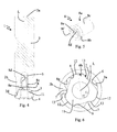
FIG. 7: shows a perspective illustration of the tool shank in the embodiment;
FIG. 8: shows a sectional illustration of the tool shank;
FIG. 9: shows a perspective illustration of a cutting head in the embodiment;
FIG. 10: shows a further perspective illustration of the cutting head;
FIG. 11: shows a plan view of the front side of the cutting head;
FIG. 12: shows a plan view of the rear side of the cutting head;
FIG. 13: shows a section perpendicular to the longitudinal axis in the region of a protrusion and of a recess of a clamping connection in a first position;
FIG. 14: shows a section perpendicular to the longitudinal axis in the region of the protrusion and of the recess in a second position;
FIG. 15: shows a basic illustration corresponding to FIG. 11 to explain the clamping connection between the cutting head and the tool shank; and
FIG. 16: shows a basic illustration corresponding to FIG. 12 to explain the clamping connection.
DESCRIPTION OF THE INVENTION
A milling tool 1 according to one embodiment of the present invention is described in the following text with reference to FIGS. 1 to 16.
The milling tool 1 has a tool shank 2, which is configured to be fastened by way of a rear end 2 a to a corresponding receptacle in a milling machine. The tool shank 2 has a longitudinal axis L, which simultaneously forms the rotation axis of the milling tool 1 during operation of the milling tool 1 in a milling machine. The tool shank 2 has substantially a cylindrical basic shape, wherein, in the exemplary embodiment illustrated, the outside diameter at a front end 2 b opposite the rear end 2 a is somewhat smaller than at the rear end 2 a.
As can be seen in particular in FIG. 1 to FIG. 3, the tool shank 2 has on its outer circumference a notch 2 c for fastening to the receptacle of the milling machine in a rotationally locked manner.
Formed at the front end 2 b of the tool shank 2 is a recess 3, which will be described in more detail in the following text. The recess 3 is configured such that a cutting head is fastenable to the front side of the tool shank 2. The recess 3 is surrounded at the front end 2 b by a flat abutment face 2 d, which extends perpendicularly to the longitudinal axis L of the tool shank 2 and forms a large support for the cutting head 4 fastened to the tool shank 2.
As can be seen in particular in FIG. 7 and FIG. 8, the recess 3 has, next to the free end, a first portion 3 a having a relatively large cross section. The first portion 3 a is adjoined, via a shoulder 3 b, by a substantially cylindrical second portion 3 c having a smaller cross section, which is adjoined, via a further shoulder, by a threaded bore 5 coaxial with the longitudinal axis L. The threaded bore 5 is embodied as a blind hole, which is provided with an internal thread, the function of which will be described in more detail. In the direction perpendicular to the longitudinal axis L, the threaded bore 5 has a cross section which is smaller than the cross section of the first portion 3 a of the recess 3.
The shape of the first portion 3 a of the recess 3 will be explained in more detail with reference to FIG. 6 and FIG. 7. As can be seen in FIG. 6, the first portion 3 a has, in the plane perpendicular to the longitudinal axis L, a shape which is similar to a stylized three-leaf clover. The side walls of the recess 3 are formed in the first portion 3 a by three centering faces 6, between which radially inwardly protruding stop portions 7 are formed. The centering faces 6 and the stop portions 7 are in this case distributed regularly around the circumference of the first portion 3 a, such that the first portion 3 a has n-fold symmetry with respect to a rotation about the longitudinal axis L, where n=3. In other words, the first portion 3 a has three-fold rotational symmetry with respect to the longitudinal axis L. The centering faces 6 are formed in a concave manner. The stop portions 7 are formed in a convex manner in a section perpendicular to the longitudinal axis L, such that they form radially inwardly protruding protrusions. In the exemplary embodiment illustrated, the centering faces 6 and the stop portions 7 extend in each case at least substantially parallel to the longitudinal axis L. According to one development, however, it is for example also possible for the internal cross section of the first portion 3 a to narrow in the direction from the front end 2 b to the rear end 2 a of the tool shank 2.
As is explained by way of example with regard to one of the centering faces 6, the centering face 6 have, in a section perpendicular to the longitudinal axis L, a first region 6 a, in which the centering faces 6 are at a first distance from the longitudinal axis L. In the embodiment illustrated, the first region 6 a transitions continuously into a second region 6 b, in which the centering faces 6 are at a smaller, second distance from the longitudinal axis L. In other words, the surfaces of the centering faces 6 approach the longitudinal axis L with continued progress around the longitudinal axis L. In the embodiment illustrated, the centering faces 6 are oriented such that, with a viewing direction toward the front end 2 b of the tool shank 2, they approach the longitudinal axis L with continued progress in the clockwise direction around the longitudinal axis L. However, depending on the intended direction of rotation of the milling tool 1, it is for example also possible to configure the centering faces 6 such that they approach the longitudinal axis L with continued progress in the counterclockwise direction. In any case, it is preferred for the centering faces 6 to approach the longitudinal axis L with continued progress counter to the intended direction of rotation when the milling tool 1 is used. Preferably, the centering faces 6 have in this case a concavely curved shape. The centering faces 6 can for example preferably have a cylindrically or elliptically curved shape, such that they approach the longitudinal axis L as uniformly as possible with continued rotation.
As can be seen in particular in FIG. 3, FIG. 4 and FIG. 5, provision is also made of a threaded bush 8, which is received at least partially in the threaded bore 5. The threaded bush 8 has a threaded portion 8 a, which is provided at least regionally with an external thread 8 c, which is intended to interact with the internal thread of the threaded bore 5. The threaded bush 8 also has a head portion 8 b. In the embodiment illustrated, the head portion 8 b has a somewhat larger external circumference than the threaded portion 8 a. The head portion 8 b is dimensioned such that, when the threaded portion 8 a is screwed into the threaded bore 5, it can be received in the second portion 3 c of the recess 3. The threaded bush 8 has, at least in the head portion 8 b, an outside diameter which is larger than the diameter of a bore 10 in the cutting head 4, as will be described in more detail. The front side 8 f of the head portion 8 b has a face which is configured to press against an underside of the cutting head 4. In the threaded portion 8 a, the threaded bush 8 is furthermore provided at least regionally with an internal thread 8 d, which is configured to interact with an external thread of a fastening screw 9 in order to fasten the cutting head 4 to the tool shank 2.
In the region of the head portion 8 b, the threaded bush 8 is furthermore provided on its inner side with a profile 8 e for engagement by a screwdriving tool. In the embodiment illustrated, the profile 8 e for engagement by a screwdriving tool is configured for example as a hexagon socket. However, some other shape, which allows interaction with a corresponding screwdriving tool, is also possible. As can be seen in particular in FIG. 4, the profile 8 e for engagement by a screwdriving tool has a free internal cross section which is somewhat larger than the diameter of the internal thread 8 d. As a result, the external thread of the fastening screw 9 can be guided through the head portion 8 b to the internal thread 8 d.
The configuration of the cutting head 4 in the present exemplary embodiment will now be described in more detail with reference to FIG. 9 to FIG. 12. The cutting head 4 is configured in the embodiment as an integral component produced from hard metal or cermet in a powder metallurgical production process by pressing and sintering. The cutting head 4 is provided with a plurality of cutting edges 4 a for machining a workpiece. In the exemplary embodiment illustrated in the figures, the cutting head 4 is configured specifically for high-feed milling, as is apparent from the arrangement of the cutting edges 4 a. However, it is also possible to provide cutting edges of different types, such that the cutting head 4 can be used for other milling operations.
The cutting head 4 is provided with a bore 10 which extends in the axial direction through the cutting head 4 and penetrates the cutting head 4 from the front side 4 b to the rear side 4 c. The bore extends coaxially with a longitudinal axis of the cutting head 4, which coincides with the longitudinal axis L of the tool shank 2. The bore 10 is configured to receive a fastening screw 9 in order to fasten the cutting head 4 to the tool shank 2. On its side facing the front side 4 b, the bore 10 has a first portion with a widened cross section, which is configured to receive the head of the fastening screw 9. The first portion has at least one abutment face 10 a, against which the underside of the head of the fastening screw 9 is supported in order to clamp the cutting head 4 against the tool shank 2. In the exemplary embodiment, the first portion has for example a cross section that narrows conically in the direction of the rear side 4 c of the cutting head 4 in order to receive a conical countersunk head of the fastening screw 9. However, other configurations are for example also possible, such as in particular a stepped configuration in order to receive a flat or cylindrical head of the fastening screw 9.
In the exemplary embodiment, the first portion transitions into a second portion 10 b, which has a smaller diameter with a substantially cylindrical cross section. The diameter of the second portion 10 b is dimensioned such that the external thread on a threaded portion of the fastening screw 9 can be guided through the second portion 10 b. The diameter of the second portion 10 b is furthermore dimensioned such that it is smaller than the outside diameter of the head portion 8 b of the threaded bush 8.
In the exemplary embodiment shown, a protrusion 11 is formed on the rear side 4 c of the cutting head 4. The protrusion 11 has a smaller external circumference than the front side 4 b of the cutting head 4, such that a flat bearing face 4 d is formed on the rear side 4 c of the cutting head 4, the cutting head 4 being supported on the flat abutment face 2 d of the tool shank 2 by way of said flat bearing face 4 d. In the exemplary embodiment, the bearing face 4 d extends around the protrusion 11 in a plane perpendicular to the longitudinal axis L. In the axial direction, the protrusion 11 has a height which is somewhat smaller than the depth of the first portion 3 a of the recess 3. This ensures that the cutting head 4 is supported reliably on the flat abutment face 2 d of the tool shank 2 by way of the bearing face 4 d. The bore 10, in particular the second portion 10 b thereof, also extends through the protrusion 11.
The protrusion 11 and the recess 3 together form a part of a clamping connection between the cutting head 4 and the tool shank 2. In this case, the protrusion 11 and the recess 3 effect clamping in an interacting manner, as will be described in more detail.
The external contour of the protrusion 11 is described in more detail in the following text with reference to FIG. 6, FIG. 10 and FIG. 12. The protrusion 11 has a plurality n of clamping faces 12, which are configured to interact with the centering faces 6 of the recess 3. In the exemplary embodiment, the protrusion 11 has three clamping faces 12 (n=3). The clamping faces 12 extend along the contour of a common circle, the center of which is located on the longitudinal axis L, in a section perpendicular to the longitudinal axis L. The clamping faces 12 form the radially furthest protruding regions of the protrusion 11 in the section perpendicular to the longitudinal axis L. In the exemplary embodiment illustrated, the clamping faces 12 extend along a common cylinder surface, wherein the cylinder axis corresponds to the longitudinal axis L. As has already been described with regard to the first portion 3 a of the recess 3, it is for example also possible to configure the protrusion 11 such that the external circumference thereof narrows slightly toward the side facing the tool shank 2. In this case, the clamping faces 12 can for example also extend along a common cone surface, wherein the code axis extends along the longitudinal axis L. Although clamping faces 12 which are configured in a relatively extensive manner are illustrated in the exemplary embodiment, said clamping faces having a relatively large extent both in the axial direction and in the tangential direction, the size of the clamping faces 12 can also be reduced without having a significant effect on functioning. In an extreme case, the clamping faces 12 can be reduced to virtually punctiform contact regions with the centering faces 6.
The clamping faces 12 are distributed symmetrically around the circumference of the protrusion 11 and flattened portions 13 for support against the radially inwardly protruding stop portions 7, which are provided in the recess 3, are arranged between the clamping faces 12. In the region of the flattened portions 13, the contour of the protrusion 11 is located completely within the common circle, along which the clamping faces 12 extend, in a section perpendicular to the longitudinal axis L. In the tangential direction, the clamping faces 12 are considerably narrower than the corresponding centering faces 6, which are formed in the recess 3. In the exemplary embodiment, the clamping faces 12 are approximately half as wide as the centering faces 6, as can be seen in FIG. 6, FIG. 13 and FIG. 14. As a result of this configuration, the protrusion 11 has, in a section perpendicular to the longitudinal axis L, a contour which corresponds approximately to an isosceles triangle with rounded corners, wherein the rounded corners are formed by the clamping faces 12.
As can be seen in FIG. 9 to FIG. 12, the cutting head 4 is formed in a manner free of undercuts, thereby allowing direct powder metallurgical production by pressing and sintering, wherein mechanical reworking by grinding is necessary only in the region of the cutting edges 4 a.
The fastening of the cutting head 4 to the tool shank 2 and the releasing of said cutting head 4 from said tool shank 2 will now be described in more detail with reference to FIG. 3 and FIG. 13 to FIG. 16.
In order to fasten the cutting head 4 to the tool shank 2, first of all the threaded bush 8 is screwed into the threaded bore 5 in the tool shank 2, such that the head portion 8 b of the threaded bush 8 is received in the second portion 3 c of the recess 3. Subsequently, the protrusion 11 is introduced into the first portion 3 a of the recess 3, wherein the clamping faces 12 are arranged opposite the first regions 6 a of the centering faces 6 for introducing purposes, as is illustrated in FIG. 13 and FIG. 15. The distance of the first regions 6 a of the centering faces 6 from the longitudinal axis L is selected such that it is somewhat greater than the distance of the clamping faces 12 from the longitudinal axis L, such that the protrusion 11 can be introduced into the recess 3 in this orientation. The cutting head 4 and the tool shank 2 are moved toward one another in the longitudinal direction until the bearing face 4 d of the cutting head 4 is supported against the abutment face 2 d of the tool shank 2.
By rotation of the cutting head 4 about the longitudinal axis L relative to the tool shank 2, the clamping faces 12 of the protrusion 11 are moved in the tangential direction from the first regions 6 a to the second regions 6 b of the centering faces 6 in the recess 3, as is illustrated in FIG. 14 and FIG. 16. In the process, the clamping faces 12 move along the centering faces 6. The distance of the second regions 6 b of the centering faces 6 from the longitudinal axis L is selected such that it is somewhat smaller than the distance of the clamping faces 12 from the longitudinal axis L. During the rotation of the cutting head 4 relative to the tool shank 2, the centering faces 6 thus press against the clamping faces 12 substantially in the radial direction, such that a force-fitting clamping connection is formed between the clamping faces 12 and the centering faces 6. During this movement, centering of the cutting head 4 relative to the tool shank 2 takes place at the same time.
The possible rotation of the cutting head 4 relative to the tool shank 2 is limited by the stop portions 6 and the flattened portions 13, interacting therewith, which prevent further relative movement when the clamping faces 12 are located opposite the second regions 6 b of the centering faces 6. As a result of this limiting of further rotation, the acting force for the force-fitting connection of the cutting head 4 to the tool shank 2 can be determined reliably via the angle which the centering faces 6 enclose with the clamping faces 12 in their contact region, and by the possible angle of rotation which is given substantially by the width of the clamping faces 12 compared with the width of the centering faces 6 in the tangential direction. The angle which the centering faces 6 enclosed with the clamping faces 12 in the contact region can in this case be determined via the extent to which the centering faces 6 approach to the longitudinal axis from the first region 6 a to the second region 6 b. In the exemplary embodiment, during the movement into the clamping position, a relative rotation of the cutting head 4 through about 35° with respect to the tool shank 2 is allowed. In order to achieve reliable force-fitting fastening, a relative rotation through at least 15°, preferably at least 20°, more preferably at least 25° should be allowed.
The forces, acting virtually exclusively in the radial direction, of the force-fitting connection between the clamping faces 12 and the centering faces 6 have the result that self-locking occurs, preventing the cutting head 4 from detaching from the tool shank 2 again.
The fastening of the cutting head 4 to the tool shank 2 is concluded in that the fastening screw 9 is guided by way of its threaded portion through the bore 10 and is screwed into the internal thread 8 d of the threaded bush 8 until the underside of the head of the fastening screw 9 is supported on the abutment face 10 c of the bore 10. As a result of the already formed force-fitting connection between the cutting head 4 and the tool shank 2, the forces acting on the fastening screw 9 during operation of the milling tool 1 are very low.
In order to release the cutting head 4 from the tool shank 2, the fastening screw 9 is screwed out of the internal thread 8 d of the threaded bush 8 again and removed from the milling tool 1. On account of the force-fitting connection which is formed between the clamping faces 12 and the second regions 6 b of the centering faces 6, the cutting head 4 is not yet released from the tool shank 2 in this state. Once the fastening screw 9 has been removed, a screwdriving tool, for example a hexagon screwdriving tool, can be guided through the bore 10 and can be brought into engagement with the profile 8 a for engagement by a screwdriving tool in the threaded bush 8. By screwing the threaded bush 8 out of the threaded bore 5, the front side 8 f of the threaded bush 8 moves against the underside of the cutting head 4, such that, as a result of continued screwing out of the threaded bush 8, the force-fitting connection between the cutting head 4 and the tool shank 2 can be released in that the protrusion 11 is pushed out of the first portion 3 a of the recess 3. In this way, reliable releasing of the cutting head 4 from the tool shank 2 is allowed even when relatively large clamping forces act between the clamping faces 12 and the second regions 6 b of the centering faces 6.
Variation
Although an embodiment in which the protrusion 11 of the clamping connection is formed on the cutting head 4 and the recess 3 is formed on the tool shank 2 has been described, it is also possible to provide an opposite arrangement of the protrusion 11 and recess. In this case, the protrusion 11 is provided on the front side of the tool shank 2 and has, in the same way, the clamping faces 12 and the flattened portions 13, and the recess 3 is formed in the rear side 4 c of the cutting head 4 and has, in the same way, the centering faces 6 and the abutment portions 7 formed between the latter. In this case, too, the threaded bush 8 can be provided and arranged in a coaxial bore which extends from the free end into the protrusion 11.

Claims (16)

The invention claimed is:
1. A milling tool, comprising:
a tool shank having a longitudinal axis and a forward end;
a cutting head fastened to said forward end of said tool shank, said cutting head having a plurality of cutting edges for machining a work piece;
a clamping connection interconnecting said cutting head with said tool shank, said clamping connection having a protrusion circumferentially formed with a plurality of clamping faces, and a recess circumferentially formed with a plurality of centering faces configured to interact with said clamping faces;
each of said centering faces in said recess having a first region and a second region, said first region of said centering faces being spaced apart from said longitudinal axis by a first spacing distance, in a section perpendicular to said longitudinal axis, said first region merging into said second region in which said centering faces are spaced apart from said longitudinal axis by a smaller second distance in the section perpendicular to said longitudinal axis, wherein said protrusion is introducible into said recess with said clamping faces between said first regions of said centering faces and said clamping face are movable, by rotation of said cutting head about said longitudinal axis relative to the tool shank, into a clamping position in which said clamping faces interact by way of a force-fit with said second regions of said centering faces; and
said recess being formed with a plurality of radially inwardly projecting stop portions between said centering faces, said stop portions being configured for limiting a rotation of said cutting head about said longitudinal axis relative to said tool shank.
2. The milling tool according to claim 1, wherein said clamping faces extend in a common circle, and said common circle has a center located on said longitudinal axis, when viewed in a section perpendicular to said longitudinal axis.
3. The milling tool according to claim 1, wherein said clamping faces extend along a common cylinder surface or a common cone surface having an axis of symmetry coinciding with said longitudinal axis of said tool shank.
4. The milling tool according to claim 1, wherein said protrusion is formed with three clamping faces.
5. The milling tool according to claim 1, wherein said clamping faces form a radially farthest protruding regions of said protrusion in a section perpendicular to said longitudinal axis.
6. The milling tool according to claim 1, wherein said cutting head is formed with a bore for receiving a fastening screw, said bore extending in an axial direction through said cutting head.
7. The milling tool according to claim 6, wherein said tool shank is formed with a threaded bore coaxial to said bore in said cutting head, for fastening said cutting head to said tool shank.
8. The milling tool according to claim 7, further comprising a threaded bush having an external thread for meshing with said threaded bore in said tool shank, and an internal thread for meshing with a fastening screw for fastening said cutting head.
9. The milling tool according to claim 8, wherein said threaded bush has an outside diameter, at least on a side facing said cutting head, which is greater than an inside diameter of said bore in said cutting head.
10. The milling tool according to claim 8, wherein said threaded bush, on a side facing towards said cutting head, is formed with a profile for engagement by a screw driving tool.
11. The milling tool according to claim 10, wherein said bore formed in said cutting head for receiving said fastening screw has a diameter coordinated with said profile for engagement by the screw driving tool such that the screw driving tool may be brought into engagement with said profile through said bore in said cutting head.
12. The milling tool according to claim 1, wherein said protrusion of said clamping connection is formed integrally with said cutting head and said recess of said clamping connection is formed in said forward end of said tool shank.
13. The milling tool according to claim 1, wherein the protrusion of the clamping connection is formed integrally with said tool shank and said recess of said clamping connection is formed in said cutting head.
14. The milling tool according to claim 1, wherein said cutting head is formed of a hard material.
15. The milling tool according to claim 14, wherein said hard material is selected from the group consisting of hard metal and cermet.
16. A method for fastening a cutting head to a tool shank of a milling tool, the tool shank having a longitudinal axis and the cutting head having a plurality of cutting edges for machining a work piece, wherein the tool shank and the cutting head are connected to one another via a clamping connection, the clamping connection having a protrusion formed circumferentially with a plurality of clamping faces, flattened portions between adjacent ones of the clamping faces, and a recess formed circumferentially with a plurality of centering faces configured to interact with the clamping faces, and stop portions projecting radially inward relative to the centering faces, the stop portions being between the centering faces wherein the centering faces each have a first region in which the centering faces are located at a first distance from the longitudinal axis, in a section perpendicular to the longitudinal axis, and the first region merges into a second region in which the centering faces are at a smaller second distance from the longitudinal axis in the section perpendicular to the longitudinal axis,
the method comprising:
introducing the protrusion into the recess with the clamping faces of the protrusion between the first regions of the centering faces;
subsequently rotating the cutting head about the longitudinal axis relative to the tool shank into a clamping position, to thereby mutually engage the clamping faces with the second regions of the centering faces in a force-fitting connection and in the clamping position, the stop portions and the flattened portions interacting therewith prevent further relative rotation.
US14/769,732 2013-02-22 2014-02-18 Milling tool Active US9669478B2 (en)

Applications Claiming Priority (4)

Application Number Priority Date Filing Date Title
ATGM60/2013 2013-02-22
ATGM60/2013U AT13498U1 (en) 2013-02-22 2013-02-22 milling tool
AT60/2013 2013-02-22
PCT/AT2014/000032 WO2014127391A1 (en) 2013-02-22 2014-02-18 Milling tool

Publications (2)

Publication Number Publication Date
US20150375309A1 US20150375309A1 (en) 2015-12-31
US9669478B2 true US9669478B2 (en) 2017-06-06

Family

ID=49955562

Family Applications (1)

Application Number Title Priority Date Filing Date
US14/769,732 Active US9669478B2 (en) 2013-02-22 2014-02-18 Milling tool

Country Status (7)

Country Link
US (1) US9669478B2 (en)
EP (1) EP2958693B1 (en)
CN (1) CN105142833B (en)
AT (1) AT13498U1 (en)
ES (1) ES2734351T3 (en)
PL (1) PL2958693T3 (en)
WO (1) WO2014127391A1 (en)

Cited By (2)

* Cited by examiner, † Cited by third party
Publication number Priority date Publication date Assignee Title
US20150003922A1 (en) * 2013-06-26 2015-01-01 Vargus Ltd. Cutting insert and a tool holder with a seat for cutting insert
US20230008503A1 (en) * 2019-10-31 2023-01-12 Dino Paoli S.R.L. Socket-shaft connection assembly of pneumatic impact wrench

Families Citing this family (14)

* Cited by examiner, † Cited by third party
Publication number Priority date Publication date Assignee Title
US9089911B2 (en) * 2013-01-31 2015-07-28 Gil Espinosa Side milling arbor with quad drive key assist
DE202014000866U1 (en) * 2014-02-03 2015-05-06 Johne & Co. Präzisionswerkzeuge GmbH Tool head element for manufacturing a tool head, tool head and tool receiving means
CN107457440A (en) * 2016-06-03 2017-12-12 益壮企业有限公司 Assembling structure of processing tool
US10857641B2 (en) 2017-08-18 2020-12-08 Rolls-Royce Corporation Tool for facilitating the machining of recessed inserts
DE102018112865B3 (en) * 2018-05-29 2019-10-17 Hartmetall-Werkzeugfabrik Paul Horn Gmbh Wälzschälwerkzeug
DE102019112547A1 (en) 2019-05-14 2020-11-19 Felss Systems Gmbh Processing unit and processing machine for processing a workpiece on a workpiece wall and a method for producing a processing unit of the type mentioned
CN110102809A (en) * 2019-05-31 2019-08-09 江门市中刀精密科技有限公司 A kind of milling cutter
EP4011533A4 (en) * 2019-08-09 2023-09-06 MOLDINO Tool Engineering, Ltd. CUTTING TOOL WITH REPLACEABLE HEAD, CUTTING HEAD AND TOOL BODY
DE102019135435A1 (en) * 2019-12-20 2021-06-24 Hartmetall-Werkzeugfabrik Paul Horn Gmbh Tool and method for machining a workpiece
EP3922382A1 (en) * 2020-06-09 2021-12-15 Euroexport Gb Eood System for quick change attachment of tools
TWI778459B (en) * 2020-11-27 2022-09-21 張新添 Combined chamfering tool
CN113523433A (en) * 2021-08-11 2021-10-22 一汽解放汽车有限公司 a milling cutter
CN116638361B (en) * 2023-05-25 2024-09-27 江苏苏驭研智能设备有限公司 Floating milling cutter for removing flash on bottom surface of battery tray
CN118990113A (en) * 2024-10-22 2024-11-22 宁波川景誉机械科技发展有限公司 Train track repairing milling cutter, using method and application thereof

Citations (26)

* Cited by examiner, † Cited by third party
Publication number Priority date Publication date Assignee Title
US2158120A (en) * 1936-02-19 1939-05-16 Charles A Hirschberg Detachable drill bit
US2219907A (en) * 1938-04-11 1940-10-29 Walter F Ross Tool holder assembly
DE1253015B (en) 1965-04-23 1967-10-26 Koelle Maschb G M B H Milling mandrel
US3566947A (en) * 1969-04-29 1971-03-02 John A Jukes Self-locking threaded insert
US3711105A (en) 1970-11-12 1973-01-16 Eltee Inc Tool holding system
US4325665A (en) * 1979-07-26 1982-04-20 John A. Jukes Threaded metal insert
EP0284745A2 (en) 1987-03-26 1988-10-05 Gottlieb Gühring Kg Coupling between a tool head and a tool carrier
WO1994023874A1 (en) 1993-04-14 1994-10-27 Zettl GmbH CNC Präzisions- und Sonderwerkzeuge Cutting tool
US5542795A (en) 1995-01-30 1996-08-06 Kennametal Inc. Plunge and face milling cutter with universal insert seats
US5551811A (en) * 1993-02-18 1996-09-03 Iscar, Ltd. Tool assembly having interfitting male and female coupling members
DE19600239C1 (en) 1996-01-05 1997-04-10 Ima Maschinenfabriken Klessmann Gmbh Milling machine for swarf-removing machining of workpieces of wood and/or wood substitute material
US6276879B1 (en) * 1998-08-13 2001-08-21 Iscar Ltd. Cutting head for mounting on a tool holder in a self-clamping manner
US20020053266A1 (en) * 2000-06-27 2002-05-09 Lars-Erik Enquist Positional adjusting mechanism for a cutting insert
WO2003101650A1 (en) 2002-06-04 2003-12-11 Iscar Ltd. Rotary cutting tool
DE20306151U1 (en) 2003-04-16 2004-06-03 Pokolm, Franz-Josef Milling cutter for contour finishing has region formed by cutters acting with shaft via releasable positive connection
DE10255270A1 (en) 2002-11-21 2004-06-03 Vargus Ltd. Tool for machining workpieces, especially in universal machines by milling, comprises an integrated mounting device for removably fixing a cutting insert on a tool holder
CN1610590A (en) 2002-01-29 2005-04-27 山特维克公司 Tool coupling for rotating tools
CN1620351A (en) 2002-02-15 2005-05-25 迪哈特股份公司 Machine reamer
DE202006014812U1 (en) 2006-09-27 2006-12-07 Reiner Quanz Gmbh & Co. Kg Tool socket for rotary drill or rotating tool has socket opening which internal cross section larger than maximum radius of insertable clamping shaft and with rigid entrainment lugs with inward facing contact bearing areas for secure clamp
US20070081872A1 (en) 2005-10-05 2007-04-12 Sandvik Intellectual Property Ab Milling cutter head and a milling cutter tool
US20070220731A1 (en) * 2006-03-23 2007-09-27 Hardinge, Inc. Apparatus and method for engaging components through thermal contraction
DE202008014738U1 (en) 2008-11-06 2009-01-15 Reiner Quanz Gmbh & Co. Kg Drive coupling and receiving part and clamping part for rotary drives
US7775751B2 (en) * 2005-11-06 2010-08-17 Iscar, Ltd. Rotary cutting tool
US20120039676A1 (en) * 2010-08-16 2012-02-16 Iscar, Ltd. T-Slot Cutter Having Separate Centering and Torque-Transmitting Portions
US20120099938A1 (en) 2010-01-26 2012-04-26 Iscar Ltd. Cutting Tool and Coupling Mechanism Therefor
DE102012212146A1 (en) 2012-07-11 2014-01-16 Kennametal Inc. Clutch point for a modular rotary tool and tool head and support for such a modular rotary tool

Patent Citations (34)

* Cited by examiner, † Cited by third party
Publication number Priority date Publication date Assignee Title
US2158120A (en) * 1936-02-19 1939-05-16 Charles A Hirschberg Detachable drill bit
US2219907A (en) * 1938-04-11 1940-10-29 Walter F Ross Tool holder assembly
DE1253015B (en) 1965-04-23 1967-10-26 Koelle Maschb G M B H Milling mandrel
US3566947A (en) * 1969-04-29 1971-03-02 John A Jukes Self-locking threaded insert
US3711105A (en) 1970-11-12 1973-01-16 Eltee Inc Tool holding system
US4325665A (en) * 1979-07-26 1982-04-20 John A. Jukes Threaded metal insert
EP0284745A2 (en) 1987-03-26 1988-10-05 Gottlieb Gühring Kg Coupling between a tool head and a tool carrier
US4856944A (en) 1987-03-26 1989-08-15 Gottlieb Guhring Kg Coupling between a tool head and a tool support
US5551811A (en) * 1993-02-18 1996-09-03 Iscar, Ltd. Tool assembly having interfitting male and female coupling members
WO1994023874A1 (en) 1993-04-14 1994-10-27 Zettl GmbH CNC Präzisions- und Sonderwerkzeuge Cutting tool
US5607263A (en) 1993-04-14 1997-03-04 Zettl Gmbh Cnc Prazisions-Und Sonderwerkzuege Cutting tool
US5542795A (en) 1995-01-30 1996-08-06 Kennametal Inc. Plunge and face milling cutter with universal insert seats
CN1174529A (en) 1995-01-30 1998-02-25 钴碳化钨硬质合金公司 Plunge and face milling cutters with universal insert pockets
DE19600239C1 (en) 1996-01-05 1997-04-10 Ima Maschinenfabriken Klessmann Gmbh Milling machine for swarf-removing machining of workpieces of wood and/or wood substitute material
US6276879B1 (en) * 1998-08-13 2001-08-21 Iscar Ltd. Cutting head for mounting on a tool holder in a self-clamping manner
US20020053266A1 (en) * 2000-06-27 2002-05-09 Lars-Erik Enquist Positional adjusting mechanism for a cutting insert
US7189039B2 (en) 2002-01-29 2007-03-13 Sandvik Intellectual Property Ab Tool coupling for rotating tools
CN1610590A (en) 2002-01-29 2005-04-27 山特维克公司 Tool coupling for rotating tools
CN1620351A (en) 2002-02-15 2005-05-25 迪哈特股份公司 Machine reamer
US20050220551A1 (en) 2002-02-15 2005-10-06 Otto Buettiker Machine reamer
US7431543B2 (en) 2002-02-15 2008-10-07 Dihart Ag Machine reamer
US7004692B2 (en) 2002-06-04 2006-02-28 Iscar Ltd. Rotary cutting tool
WO2003101650A1 (en) 2002-06-04 2003-12-11 Iscar Ltd. Rotary cutting tool
DE10255270A1 (en) 2002-11-21 2004-06-03 Vargus Ltd. Tool for machining workpieces, especially in universal machines by milling, comprises an integrated mounting device for removably fixing a cutting insert on a tool holder
DE20306151U1 (en) 2003-04-16 2004-06-03 Pokolm, Franz-Josef Milling cutter for contour finishing has region formed by cutters acting with shaft via releasable positive connection
US20070081872A1 (en) 2005-10-05 2007-04-12 Sandvik Intellectual Property Ab Milling cutter head and a milling cutter tool
US7775751B2 (en) * 2005-11-06 2010-08-17 Iscar, Ltd. Rotary cutting tool
US20070220731A1 (en) * 2006-03-23 2007-09-27 Hardinge, Inc. Apparatus and method for engaging components through thermal contraction
DE202006014812U1 (en) 2006-09-27 2006-12-07 Reiner Quanz Gmbh & Co. Kg Tool socket for rotary drill or rotating tool has socket opening which internal cross section larger than maximum radius of insertable clamping shaft and with rigid entrainment lugs with inward facing contact bearing areas for secure clamp
DE202008014738U1 (en) 2008-11-06 2009-01-15 Reiner Quanz Gmbh & Co. Kg Drive coupling and receiving part and clamping part for rotary drives
US20120099938A1 (en) 2010-01-26 2012-04-26 Iscar Ltd. Cutting Tool and Coupling Mechanism Therefor
US20120039676A1 (en) * 2010-08-16 2012-02-16 Iscar, Ltd. T-Slot Cutter Having Separate Centering and Torque-Transmitting Portions
DE102012212146A1 (en) 2012-07-11 2014-01-16 Kennametal Inc. Clutch point for a modular rotary tool and tool head and support for such a modular rotary tool
US20140017022A1 (en) 2012-07-11 2014-01-16 Kennametal, Inc. Coupling point for a modular rotary tool and tool head carrier for a modular rotary tool

Cited By (3)

* Cited by examiner, † Cited by third party
Publication number Priority date Publication date Assignee Title
US20150003922A1 (en) * 2013-06-26 2015-01-01 Vargus Ltd. Cutting insert and a tool holder with a seat for cutting insert
US9919366B2 (en) * 2013-06-26 2018-03-20 Vargus Ltd. Cutting insert and a tool holder with a seat for cutting insert
US20230008503A1 (en) * 2019-10-31 2023-01-12 Dino Paoli S.R.L. Socket-shaft connection assembly of pneumatic impact wrench

Also Published As

Publication number Publication date
WO2014127391A8 (en) 2015-09-17
EP2958693A1 (en) 2015-12-30
PL2958693T3 (en) 2019-11-29
CN105142833A (en) 2015-12-09
ES2734351T3 (en) 2019-12-05
EP2958693B1 (en) 2019-05-08
AT13498U1 (en) 2014-01-15
US20150375309A1 (en) 2015-12-31
WO2014127391A1 (en) 2014-08-28
CN105142833B (en) 2017-10-27

Similar Documents

Publication Publication Date Title
US9669478B2 (en) Milling tool
JP5839435B2 (en) Tool holder having a collet holder and tool insert used in the tool holder
EP2536522B1 (en) Tool coupling
EP2754519B1 (en) Exchangeable head cutting tool
US11396051B2 (en) Tool system and method for turning
US20030039523A1 (en) Drilling or boring tool
US20140227046A1 (en) Method and tool for producing a surface of predetermined roughness
US20130259590A1 (en) Cutting Tool Having Clamping Bolt Provided with Locking Portion and Cutting Insert Therefor
US10549366B2 (en) Whirling tool
US9669467B2 (en) Tool system
US11872643B2 (en) T-shaped tool, and method for manufacturing T-shaped tool
US8708613B2 (en) Left-handed and right-handed cutting tool
KR20110108303A (en) Rotary tools for chip removal machining and loose tops and base bodies for these rotary tools
JP2002538012A (en) Tool fitting
CN106994527B (en) Tool connection between two connection parts and connection part for a tool connection
CA3017242A1 (en) Cutting insert, tool holder and tool
US20200238391A1 (en) Whirling tool
US9296045B2 (en) Metal-cutting tool
CN102905829A (en) Milling tool and clamping screw having male grip at end thereof
CN116921719A (en) Cutting insert and tool for machining
US10710174B2 (en) Slitting cutter and tool key in combination therewith
WO2013057778A1 (en) Holder for head replacement-type cutting tool, and head replacement-type cutting tool
EP1314502A1 (en) Rotable cutting tool
EP1283082B1 (en) Rotatable cutting tool
US8702351B2 (en) Cutter body and locking screw therefor

Legal Events

Date Code Title Description
AS Assignment

Owner name: CERATIZIT AUSTRIA GMBH, AUSTRIA

Free format text: ASSIGNMENT OF ASSIGNORS INTEREST;ASSIGNORS:BURTSCHER, PETER;PRAST, JOSEF;REEL/FRAME:036409/0244

Effective date: 20150728

STCF Information on status: patent grant

Free format text: PATENTED CASE

MAFP Maintenance fee payment

Free format text: PAYMENT OF MAINTENANCE FEE, 4TH YEAR, LARGE ENTITY (ORIGINAL EVENT CODE: M1551); ENTITY STATUS OF PATENT OWNER: LARGE ENTITY

Year of fee payment: 4

MAFP Maintenance fee payment

Free format text: PAYMENT OF MAINTENANCE FEE, 8TH YEAR, LARGE ENTITY (ORIGINAL EVENT CODE: M1552); ENTITY STATUS OF PATENT OWNER: LARGE ENTITY

Year of fee payment: 8