CN113523433A - Milling reamer - Google Patents
Milling reamer Download PDFInfo
- Publication number
- CN113523433A CN113523433A CN202110917563.7A CN202110917563A CN113523433A CN 113523433 A CN113523433 A CN 113523433A CN 202110917563 A CN202110917563 A CN 202110917563A CN 113523433 A CN113523433 A CN 113523433A
- Authority
- CN
- China
- Prior art keywords
- hole
- cutter
- tool bit
- cutter head
- milling
- Prior art date
- Legal status (The legal status is an assumption and is not a legal conclusion. Google has not performed a legal analysis and makes no representation as to the accuracy of the status listed.)
- Pending
Links
Images


Classifications
-
- B—PERFORMING OPERATIONS; TRANSPORTING
- B23—MACHINE TOOLS; METAL-WORKING NOT OTHERWISE PROVIDED FOR
- B23D—PLANING; SLOTTING; SHEARING; BROACHING; SAWING; FILING; SCRAPING; LIKE OPERATIONS FOR WORKING METAL BY REMOVING MATERIAL, NOT OTHERWISE PROVIDED FOR
- B23D77/00—Reaming tools
-
- B—PERFORMING OPERATIONS; TRANSPORTING
- B23—MACHINE TOOLS; METAL-WORKING NOT OTHERWISE PROVIDED FOR
- B23C—MILLING
- B23C5/00—Milling-cutters
-
- B—PERFORMING OPERATIONS; TRANSPORTING
- B23—MACHINE TOOLS; METAL-WORKING NOT OTHERWISE PROVIDED FOR
- B23C—MILLING
- B23C9/00—Details or accessories so far as specially adapted to milling machines or cutter
Abstract
The invention discloses a milling reamer, which belongs to the technical field of cutters and comprises a cutter bar, a top fastening piece, a cutter head and a fastening piece. The first end of the cutter bar is provided with an internal threaded hole; the jacking piece is sleeved on the periphery of the first end; the cutter head is arranged at one end of the top fastening piece, which is far away from the cutter bar, and a connecting through hole is formed in the cutter head along the axial direction of the cutter head; the retaining member passes connect through hole and threaded connection in the internal thread hole, in order to incite somebody to action the tool bit lock in on the cutter arbor, top retaining member is kept away from the one end of cutter arbor can support tightly the tool bit. According to the invention, on the premise of not replacing the cutter bar, only the corresponding cutter head needs to be replaced according to the size of the hole to be processed, so that the universality of the milling reamer is improved.
Description
Technical Field
The invention relates to the technical field of cutters, in particular to a milling reamer.
Background
In the trial production and development process of the parts of the automobile products, the parts are generally required to be processed by using a cutter.
The reamer is one kind of finish machining cutter, and the wide application is to the finish machining of pore structure in the numerical control course of working. When machining a plurality of high-precision holes of different diameters of a fuel cell stack casing, a solid alloy reamer is generally used for finish machining.
In the prior art, the integral alloy reamer is generally an integral structure, and the cutting edge of the integral alloy reamer is integrally formed on the side of one end of the cutter bar. However, with the design change of automobile parts, the size of the hole structure also changes, and the diameter of the whole alloy reamer cannot be adjusted, so that the universality is poor, and the method cannot adapt to the trial production of the parts.
Disclosure of Invention
The invention aims to provide a milling reamer, which can be used for improving the universality of the milling reamer by only replacing a corresponding cutter head according to the size of a hole to be machined on the premise of not replacing a cutter bar.
As the conception, the technical scheme adopted by the invention is as follows:
a milling reamer comprising:
the cutter bar is provided with an internal threaded hole at a first end;
the jacking piece is sleeved on the periphery of the first end;
the tool bit is arranged at one end, far away from the tool bar, of the jacking piece, and a connecting through hole is formed in the tool bit along the axis direction of the tool bit;
the retaining member passes connect through hole and threaded connection in the internal thread hole, in order to incite somebody to action the tool bit lock in on the cutter arbor, top retaining member is kept away from the one end of cutter arbor can support tightly the tool bit.
Optionally, the tightening member includes:
the periphery of the first end is provided with an external thread part which is in threaded fit with the adjusting locking ring;
the sliding sleeve is sleeved on the periphery of the first end and located between the adjusting locking ring and the tool bit, the end face, away from the adjusting locking ring, of the sliding sleeve is a jacking face, and the jacking face can be tightly abutted to the tool bit.
Optionally, the cutter arbor includes the cutter arbor body and locates coaxially the throat portion of the one end of cutter arbor body, the internal thread hole is located in the throat portion, the throat portion includes:
the circular truncated cone transition part is in a circular truncated cone structure, and the large-diameter end is connected with the end part of the cutter bar body;
the external thread part is arranged at the small-diameter end of the circular truncated cone transition part;
the smooth axial region is located the external screw thread portion is kept away from the one end of round platform transition portion, slip cap slidable sleeve is located outside the smooth axial region.
Optionally, one end of the sliding sleeve close to the jacking surface is rounded.
Optionally, an elastic washer is arranged between the tightening surface and the cutter head.
Optionally, the connection through hole includes a connection hole, and the connection hole includes:
the taper hole part is arranged at one end of the cutter head far away from the top piece, the hole diameter of the taper hole part is gradually reduced along the direction that the cutter head is close to the top piece, and the end part of the locking piece can sink into the taper hole part;
and the cylindrical hole part is communicated with the small-diameter end of the conical hole part.
Optionally, the connecting hole still includes spacing notch portion, spacing notch portion locates the periphery side of connecting hole and with the connecting hole intercommunication, the periphery of retaining member is provided with spacing post, spacing post can the joint in spacing notch portion.
Optionally, the retaining member is of an integrally formed structure, including:
the periphery of the conical countersunk head part is provided with an external conical surface matched with the conical hole part, and the conical countersunk head part can sink into the conical hole part;
the cylindrical clamping part is arranged at the small-diameter end of the conical countersunk head part, a plurality of limiting columns are arranged at intervals along the circumferential direction of the cylindrical clamping part, and the limiting slot hole parts are correspondingly clamped with the limiting columns one by one;
the cylindrical locking part is arranged at one end, away from the conical countersunk head part, of the cylindrical clamping part, the diameter of the cylindrical locking part is smaller than that of the cylindrical clamping part, and external threads matched with the internal thread hole are arranged at the end part of the cylindrical locking part.
Optionally, the cutter head comprises:
the connecting through hole penetrates through the cutter head body, and a plurality of blade mounting positions are arranged on the periphery of the cutter head body at intervals around the circumference of the cutter head body;
the blade, every all can be dismantled on the blade installation position and be provided with one the blade.
Optionally, the milling reamer further comprises a compression elastic piece, the compression elastic piece is sleeved at the first end of the cutter rod, one end of the compression elastic piece is abutted to the cutter rod, and the other end of the compression elastic piece is abutted to the jacking piece.
When the milling reamer is used, the second end of the cutter bar is clamped on a corresponding machine tool, and a cutter head arranged at the first end of the cutter bar is used for machining a workpiece. Because the tool bit can be dismantled through the retaining member with the cutter arbor and be connected, designer can design the tool bit of a series of sizes in order to adapt to the not unidimensional hole structure of treating of milling when designing to improve the commonality of reamer. Locking member exerts the locking force towards the cutter arbor to the cutter arbor, and the one end that the cutter arbor was kept away from to the tight piece in top can support tight cutter arbor to the tight piece in top can exert the tight power in top of keeping away from the cutter arbor to the top, and locking member and the tight piece combined action in top guarantee that the cutter head is stable to be installed on the cutter arbor, avoid the cutter head to take place to rock, guarantee the stable state of cutter head in the course of working, thereby guarantee processingquality.
Drawings
In order to more clearly illustrate the technical solutions in the embodiments of the present invention, the drawings used in the description of the embodiments of the present invention will be briefly described below, and it is obvious that the drawings in the following description are only some embodiments of the present invention, and for those skilled in the art, other drawings can be obtained according to the contents of the embodiments of the present invention and the drawings without creative efforts.
Fig. 1 is a schematic structural diagram of a milling reamer according to an embodiment of the present invention;
FIG. 2 is a first exploded view of a milling reamer according to a first embodiment of the present invention;
fig. 3 is an exploded view of a milling reamer according to a first embodiment of the present invention;
FIG. 4 is a schematic view of a tool tip provided in accordance with an embodiment of the present invention;
FIG. 5 is a schematic structural view of a retaining member according to an embodiment of the present invention;
fig. 6 is a schematic view of a compression spring disposed on a tool bar according to a second embodiment of the present invention.
In the figure:
1. a cutter bar; 11. an internally threaded bore; 12. a reducing portion; 121. an external threaded portion; 122. a circular truncated cone transition part; 123. a light axis part; 124. the compression elastic piece is sleeved on the shaft part;
2. a top tightening member; 21. adjusting a locking ring; 22. a sliding sleeve; 221. a top tight surface;
3. a cutter head; 31. a connecting through hole; 311. a taper hole portion; 312. a cylindrical hole portion; 313. limiting the notch hole part; 32. a blade; 33. a tool bit body; 331. a first positioning surface;
4. a locking member; 41. a conical countersink; 42. a cylindrical chucking part; 421. a limiting column; 43. a cylindrical locking portion;
5. compressing the resilient member.
Detailed Description
In order to make the technical problems solved, the technical solutions adopted and the technical effects achieved by the present invention clearer, the technical solutions of the present invention are further described below by way of specific embodiments with reference to the accompanying drawings. It is to be understood that the specific embodiments described herein are merely illustrative of the invention and are not limiting of the invention. It should be further noted that, for the convenience of description, only some but not all of the elements associated with the present invention are shown in the drawings.
In the description of the present invention, it should be noted that the terms "center", "upper", "lower", "left", "right", "vertical", "horizontal", "inner", "outer", etc., indicate orientations or positional relationships based on the orientations or positional relationships shown in the drawings, and are only for convenience of description and simplicity of description, but do not indicate or imply that the device or element being referred to must have a particular orientation, be constructed and operated in a particular orientation, and thus, should not be construed as limiting the present invention. Furthermore, the terms "first," "second," and the like are used for descriptive purposes only and are not to be construed as indicating or implying relative importance. Wherein the terms "first position" and "second position" are two different positions.
In the description of the present invention, it should be noted that unless otherwise explicitly stated or limited, the terms "mounted," "connected," and "connected" are to be construed broadly, e.g., as meaning either a fixed connection or a removable connection; can be mechanically or electrically connected; they may be connected directly or indirectly through intervening media, or they may be interconnected between two elements. The specific meanings of the above terms in the present invention can be understood in specific cases to those skilled in the art.
Example one
Referring to fig. 1 to 5, the present embodiment provides a milling reamer, which can replace a cutter head with a corresponding size according to the size of a hole structure of an automobile product part, improve the versatility of the milling reamer, and save the production cost.
Referring to fig. 1 to 3, in the present embodiment, the milling reamer includes a holder 1, a top retainer 2, a bit 3, and a locking member 4.
The first end of the cutter bar 1 is provided with an internal threaded hole 11; the top tightening piece 2 is sleeved on the periphery of the first end; the tool bit 3 is arranged at one end of the top member 2 far away from the tool bar 1, and a connecting through hole 31 is formed in the tool bit 3 along the axial direction of the tool bit 3; retaining member 4 passes connecting through hole 31 and threaded connection in internal thread hole 11 to lock tool bit 3 on cutter arbor 1, the one end that the cutter arbor 1 was kept away from to top tight 2 can support tight tool bit 3.
When the milling reamer provided by the embodiment is used, the second end of the cutter bar 1 is clamped on a corresponding machine tool, and a tool bit 3 arranged at the first end of the cutter bar 1 is used for processing a workpiece. Because tool bit 3 can be dismantled with cutter arbor 1 through retaining member 4 and be connected, the designer can design the tool bit 3 of a series of sizes in order to adapt to the not unidimensional hole structure of treating of equidimension when designing to improve the commonality of milling the reamer. Retaining member 4 exerts the locking force towards cutter arbor 1 to cutter head 3, and the one end that cutter arbor 1 was kept away from to top tight 2 can support tight cutter head 3 to top tight 2 can exert the top tight power of keeping away from cutter arbor 1 to cutter head 3, and retaining member 4 and the tight 2 combined action in top guarantee that cutter head 3 stable installation is on cutter arbor 1, guarantee the stable state of cutter head 3 in the course of working, thereby guarantee processingquality.
Preferably, the material of cutter arbor 1 is quenching and tempering steel, and its inside is hollow through-hole structure to realize the inside quick cooling of cutter arbor 1.
Specifically, the designer may design a series of differently sized knife bars having a plurality of sets of different lengths and tapers.
Referring to fig. 2 and 3, in particular, in the present embodiment, the tightening member 2 includes an adjusting locking ring 21 and a sliding sleeve 22.
The outer periphery of the first end is provided with an external thread part 121 which is in threaded fit with the adjusting locking ring 21, and the adjusting locking ring 21 is in threaded connection with the external thread part 121; the sliding sleeve 22 is sleeved on the periphery of the first end and located between the adjusting locking ring 21 and the cutter head 3, the end face, away from the adjusting locking ring 21, of the sliding sleeve 22 is a jacking face 221, and the jacking face 221 can be tightly abutted to the cutter head 3.
Further, the cutter arbor 1 includes the cutter arbor body and the portion of reducing 12 of coaxial one end of locating the cutter arbor body, and the portion of reducing 12 is the first end of cutter arbor 1 promptly, and internal thread hole 11 is located in the portion of reducing 12, and the portion of reducing 12 includes external screw thread portion 121, round platform transition portion 122 and optical axis portion 123.
The circular truncated cone transition part 122 is in a circular truncated cone structure, and the large-diameter end is connected with the end part of the cutter bar body. Preferably, the diameter of the frustoconical transition portion 122 is the same as the diameter of the toolholder body. The external thread part 121 is arranged at the small-diameter end of the circular truncated cone transition part 122; the light shaft portion 123 is disposed at an end of the external thread portion 121 away from the circular truncated cone transition portion 122, and the sliding sleeve 22 is slidably sleeved outside the light shaft portion 123.
Specifically, the sliding sleeve 22 is in clearance fit with the optical axis portion 123.
When retaining member 4 locks the tool bit on cutter arbor 1, in order to further carry out the axial spacing to tool bit 3, twist soon and adjust locking ring 21 for adjust locking ring 21 and promote the slip cap 22 and move towards tool bit 3, until top tight face 221 supports tightly with tool bit 3, retaining member 4 and slip cap 22 can carry out two-way spacing to the tool bit this moment, guarantee the stability of tool bit 3 installation on cutter arbor 1.
Through the arrangement of the circular truncated cone transition portion 122, one end, away from the sliding sleeve 22, of the adjusting locking ring 21 is not in contact with the cutter bar 1, so that the cutter head 3 is prevented from extruding the adjusting locking ring 21 to be abutted against the cutter bar 1 when the locking member 4 is screwed, and excessive resistance for screwing the adjusting locking ring 21 when the adjusting locking ring 21 is extruded to be abutted against the cutter bar 1 is avoided.
Preferably, the end of the sliding sleeve 22 close to the tightening surface 221 is rounded so as to reduce the area of the tightening surface 221 and avoid the excessive sliding resistance of the sliding sleeve 22 towards the tool bit caused by the excessive contact area of the tightening surface 221 and the tool bit 3. When the adjusting locking ring 21 is screwed, the adjusting locking ring 21 may drive the sliding sleeve 22 to rotate when the adjusting locking ring is screwed to the extreme abutting position of the sliding sleeve 22, and if the contact area between the abutting surface 221 and the cutter head 3 is too large, the rotation resistance is also large, which may prevent the sliding sleeve 22 from further abutting the cutter head 3.
Preferably, the contact end surface of the sliding sleeve 22 and the adjusting locking ring 21 is also rounded.
Further preferably, an elastic washer is arranged between the abutting surface 221 and the cutter head 3 to prevent the surface quality of the cutter head 3 from being damaged when the abutting force of the sliding sleeve 22 is too large.
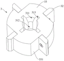
Referring to fig. 4 and 5, the coupling through-hole 31 includes a coupling hole through which the locker 4 is coupled with the female screw hole 11.
The coupling hole includes a tapered hole portion 311 and a cylindrical hole portion 312.
The taper hole part 311 is arranged at one end of the cutter head 3 far away from the top member 2, the hole diameter of the taper hole part 311 is gradually reduced along the direction that the cutter head 3 is close to the top member 2, and the end part of the locking member 4 can sink into the taper hole part 311. In the tip through retaining member 4 sinks into taper hole portion 311, retaining member 4 interferes the work of milling the reamer when avoiding milling the reamer milling plane, also avoids milling the bottom emergence of retaining member 4 and blind hole when reamer processing blind hole to interfere simultaneously. The cylindrical hole 312 communicates with the small-diameter end of the tapered hole 311.
Further, the connecting through hole 31 further comprises a limiting slot portion 313, the limiting slot portion 313 is arranged on the outer periphery of the connecting hole and communicated with the connecting hole, a limiting column 421 is arranged on the periphery of the locking member 4, and the limiting slot portion 313 and the limiting column 421 are clamped in a one-to-one correspondence mode, so that the locking member 4 can drive the cutter head 3 to rotate to be close to the cutter bar 1.
Retaining member 4 drives the rotatory cutter head 3 and is close to cutter arbor 1 when rotatory entering internal thread hole 11 to can lock cutter head 3 on cutter arbor 1 rapidly.
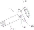
Specifically, retaining member 4 is an integrally formed structure including a tapered countersink 41, a cylindrical gripping portion 42, and a cylindrical retaining portion 43.
The outer circumference of the conical countersink 41 is provided with an outer conical surface which is engaged with the conical hole 311, and the conical countersink 41 can be sunk into the conical hole 311. Preferably, the end of the conical counter-sunk portion 41 is provided with an internal hexagonal groove, through which a tightening wrench can screw the locking element 4.
The cylindrical clamping part 42 is arranged at the small-diameter end of the conical countersunk head part 41, a plurality of limiting columns 421 are arranged at intervals along the circumferential direction of the cylindrical clamping part 42, and the plurality of limiting columns 421 are matched and clamped with the plurality of limiting slot parts 313 one by virtue of the plurality of limiting columns 421, so that the locking part 4 can be ensured to stably drive the cutter head 3 to rotate to be close to the cutter bar 1; the cylindrical locking part 43 is arranged at one end of the cylindrical clamping part 42 far away from the conical countersunk head part 41, the diameter of the cylindrical locking part 43 is smaller than that of the cylindrical clamping part 42, and the end part of the cylindrical locking part 43 is provided with an external thread matched with the internal thread hole 11.
The diameter of cylindricality chucking part 42 is greater than the diameter of cylindricality locking part 43, guarantees retaining member 4 and has sufficient mechanical strength, and retaining member 4 fracture inefficacy when avoiding cylindricality chucking part 42 to drive the tool bit 3 rotatory.
Optionally, in this embodiment, four limiting posts 421 are provided at equal intervals in the circumferential direction of the cylindrical clamping part 42, four limiting notch parts 313 are provided at equal intervals in the circumferential direction of the connecting through hole 31, and the limiting posts 421 are in one-to-one corresponding clamping connection with the limiting notch parts 313.
Referring to fig. 4, specifically, in the present embodiment, the cutter head 3 includes a cutter head body 33 and a blade 32.
The connecting through hole 31 penetrates through the tool bit body 33, and a plurality of blade mounting positions are arranged at intervals on the periphery of the tool bit body 33 around the circumference of the tool bit body 33. Each blade mounting location is removably provided with a blade 32.
Specifically, in this embodiment, four blade mounting positions are provided at intervals around the circumference of the cutter head body 33 and around the outer circumference of the cutter head body 33, and each blade mounting position includes a first positioning surface 331 and a second positioning surface that are perpendicular to each other, so as to limit the mounting of the blade 32.
Preferably, the second locating surface extends along the radial direction of the cutter head body 33, so as to ensure that the four blades 32 are arranged around the central axis of the cutter head body 33, and further ensure the accuracy of hole structure machining.
Specifically, the insert 32 is mounted on the second positioning surface by an insert fastening screw, and the insert 32 is simultaneously abutted against the first positioning surface 331.
Specifically, the blank of the bit body 33 is a cylinder, and hole machining is performed on the cylinder blank to machine the connecting through hole 31. And carrying out plane milling processing on the outer peripheral side of the cylindrical blank so as to process the blade mounting position.
Alternatively, the designer may design a series of bit bodies 33 of different diameters to accommodate different diameter hole configurations.
The milling reamer provided by the embodiment has the following advantages:
(1) the modular design of the cutter is realized, the customizing time and the customizing cost of a non-standard milling cutter are saved, designers can design the cutter bars 1 with a series of sizes and the cutter heads 3 with a series of sizes according to actual requirements, and proper cutter bars 1 and cutter heads 3 are selected according to actual processing requirements when parts are processed, so that the processing of hole structures with different diameters is rapidly completed, and the processing cost is reduced;
(2) the cutter head 3 is coaxially connected to the cutter bar 1 through a locking piece 4, and the coaxiality of the cutter head 3 after replacement is guaranteed.
Example two
Referring to fig. 6, the present embodiment provides a milling reamer, which is different from the first embodiment in that the milling reamer further includes a compression elastic member 5, the compression elastic member 5 is sleeved at a first end of the cutter bar 1, one end of the compression elastic member 5 abuts against the cutter bar 1, and the other end abuts against the tightening member 2.
Accordingly, in order to install the compression spring 5, the structure of the reduced diameter portion 12 in the present embodiment is also different from the structure of the reduced diameter portion 12 in the first embodiment.
In this embodiment, the diameter of the reduced diameter portion 12 remains unchanged and is smaller than the diameter of the tool holder body. The reduced diameter portion 12 includes a compression spring fitting shaft portion 124, an external thread portion 121, and an optical axis portion 123. The compression elastic member 5 is sleeved on the outer periphery of the compression elastic member sleeved shaft portion 124, one end of the compression elastic member abuts against the cutter bar body, the adjusting locking ring 21 is in threaded connection with the external thread portion 121, and the other end of the compression elastic member 5 abuts against the adjusting locking ring 21.
The rest of the milling reamer in this embodiment is the same as that in the first embodiment, and the description thereof is omitted.
Through setting up compression elastic component 5 for compression elastic component 5 can exert the elastic force that the orientation is kept away from the cutter arbor body to adjusting locking ring 21 all the time, thereby makes adjusting locking ring 21 can always push up slip cap 22 in the tool bit 3, prevents to lead to adjusting locking ring 21 to become loose and influence the top tight to the tool bit 3 because of the vibration in the course of working.
The foregoing embodiments are merely illustrative of the principles and features of this invention, which is not limited to the above-described embodiments, but rather is susceptible to various changes and modifications without departing from the spirit and scope of the invention, which changes and modifications are within the scope of the invention as claimed. The scope of the invention is defined by the appended claims and equivalents thereof.
Claims (10)
1. A milling reamer, comprising:
the tool comprises a tool bar (1), wherein an internal threaded hole (11) is formed in a first end of the tool bar (1);
the top fastening piece (2) is sleeved on the periphery of the first end;
the tool bit (3) is arranged at one end, far away from the tool bar (1), of the top fastening piece (2), and a connecting through hole (31) is formed in the tool bit (3) along the axial direction of the tool bit (3);
retaining member (4), pass connect through hole (31) and threaded connection in internal thread hole (11), with will tool bit (3) lock in on cutter arbor (1), top retaining member (2) are kept away from the one end of cutter arbor (1) can support tightly tool bit (3).
2. The milling reamer as claimed in claim 1, characterized in that the top piece (2) comprises:
the outer periphery of the first end of the adjusting locking ring (21) is provided with an external thread part (121) which is in threaded fit with the adjusting locking ring (21);
the sliding sleeve (22) is sleeved on the periphery of the first end and located between the adjusting locking ring (21) and the cutter head (3), the end face, far away from the adjusting locking ring (21), of the sliding sleeve (22) is a jacking face (221), and the jacking face (221) can be abutted against the cutter head (3).
3. The milling reamer as claimed in claim 2, characterized in that the shank (1) comprises a shank body and a reduction (12) coaxially provided at one end of the shank body, the internally threaded hole (11) being provided in the reduction (12), the reduction (12) comprising:
the circular truncated cone transition part (122) is in a circular truncated cone structure, and the large-diameter end of the circular truncated cone transition part is connected with the end part of the cutter bar body;
the external thread part (121) is arranged at the small-diameter end of the circular truncated cone transition part (122);
the smooth shaft part (123) is arranged at one end, away from the circular truncated cone transition part (122), of the external thread part (121), and the sliding sleeve (22) is slidably sleeved outside the smooth shaft part (123).
4. The milling reamer according to claim 2, characterized in that the sliding sleeve (22) is rounded at one end close to the top surface (221).
5. The milling reamer according to claim 2, characterized in that an elastic washer is provided between the abutment surface (221) and the cutter head (3).
6. The milling reamer as claimed in claim 1, characterized in that the connection through hole (31) comprises a connection hole comprising:
the taper hole part (311) is arranged at one end, far away from the top fastening piece (2), of the tool bit (3), the hole diameter of the taper hole part (311) is gradually reduced along the direction that the tool bit (3) is close to the top fastening piece (2), and the end part of the locking piece (4) can sink into the taper hole part (311);
and a cylindrical hole (312) which is communicated with the small-diameter end of the taper hole (311).
7. The milling reamer as claimed in claim 6, wherein the connecting through hole (31) further comprises a limiting slot portion (313), the limiting slot portion (313) is arranged on the outer periphery of the connecting hole and communicated with the connecting hole, a limiting column (421) is arranged on the outer periphery of the locking member (4), and the limiting column (421) can be clamped in the limiting slot portion (313).
8. The milling reamer according to claim 7, characterized in that the retaining member (4) is of a one-piece construction comprising:
the periphery of the conical countersunk head part (41) is provided with an external conical surface matched with the conical hole part (311), and the conical countersunk head part (41) can be sunk into the conical hole part (311);
the cylindrical clamping part (42) is arranged at the small-diameter end of the conical countersunk head part (41), a plurality of limiting columns (421) are arranged at intervals along the circumferential direction of the cylindrical clamping part (42), and the limiting notch hole parts (313) are correspondingly clamped with the limiting columns (421) one by one;
the cylindrical locking part (43) is arranged at one end, far away from the conical countersunk head part (41), of the cylindrical clamping part (42), the diameter of the cylindrical locking part is smaller than that of the cylindrical clamping part (42), and an external thread matched with the internal thread hole (11) is arranged at the end part of the cylindrical locking part (43).
9. The milling reamer as claimed in any one of claims 1 to 8, characterized in that the cutter head (3) comprises:
the tool bit body (33), the connecting through holes (31) penetrate through the tool bit body (33), and a plurality of blade mounting positions are arranged on the periphery of the tool bit body (33) at intervals around the circumference of the tool bit body (33);
and the blades (32) are detachably arranged on each blade mounting position, and one blade (32) is detachably arranged on each blade mounting position.
10. The milling reamer according to any one of claims 1 to 8, further comprising a compression elastic member (5), the compression elastic member (5) being fitted around the first end of the shank (1), one end of the compression elastic member (5) abutting against the shank (1) and the other end abutting against the abutment member (2).
Priority Applications (1)
| Application Number | Priority Date | Filing Date | Title |
|---|---|---|---|
| CN202110917563.7A CN113523433A (en) | 2021-08-11 | 2021-08-11 | Milling reamer |
Applications Claiming Priority (1)
| Application Number | Priority Date | Filing Date | Title |
|---|---|---|---|
| CN202110917563.7A CN113523433A (en) | 2021-08-11 | 2021-08-11 | Milling reamer |
Publications (1)
| Publication Number | Publication Date |
|---|---|
| CN113523433A true CN113523433A (en) | 2021-10-22 |
Family
ID=78090858
Family Applications (1)
| Application Number | Title | Priority Date | Filing Date |
|---|---|---|---|
| CN202110917563.7A Pending CN113523433A (en) | 2021-08-11 | 2021-08-11 | Milling reamer |
Country Status (1)
| Country | Link |
|---|---|
| CN (1) | CN113523433A (en) |
Citations (13)
| Publication number | Priority date | Publication date | Assignee | Title |
|---|---|---|---|---|
| GB1233953A (en) * | 1968-10-08 | 1971-06-03 | ||
| DE4033607A1 (en) * | 1990-10-23 | 1992-04-30 | Norbert Theis | TIGHTENING SCREW FOR ATTACHING A MILLING TOOL TO THE RECEIVING OF A MACHINE TOOL |
| CN101300100A (en) * | 2005-11-06 | 2008-11-05 | 伊斯卡有限公司 | Rotary cutting tool |
| CN101472699A (en) * | 2006-06-20 | 2009-07-01 | 慧星集团控股有限公司 | Machine tool and cutting ring for a machine tool |
| DE202010002058U1 (en) * | 2010-02-08 | 2011-06-09 | Johne & Co. Präzisionswerkzeuge GmbH, 46286 | Tool and tool head for machining holes and similar material recesses |
| CN101668615B (en) * | 2007-03-14 | 2013-01-02 | 瓦莱尼特有限责任公司 | Material removal tool stiffened with spacers arranged along a length |
| CN103706867A (en) * | 2013-12-25 | 2014-04-09 | 无锡雨田精密工具有限公司 | Dovetail milling cutter |
| CN105142833A (en) * | 2013-02-22 | 2015-12-09 | 森拉天时奥地利有限公司 | Milling tool |
| CN105312655A (en) * | 2014-07-28 | 2016-02-10 | 张新添 | Locking structure of disposable blade |
| CN105458404A (en) * | 2015-12-08 | 2016-04-06 | 太仓瑞鼎精密机械科技有限公司 | Rapid replacing adjustable welding reamer |
| CN208825664U (en) * | 2018-09-11 | 2019-05-07 | 上海泰锋精密刀具股份有限公司 | A kind of anti-loosening milling cutter |
| CN211841129U (en) * | 2020-01-13 | 2020-11-03 | 自贡金工超硬工具有限公司 | Quick clamping handle of a knife for cutter |
| CN212121833U (en) * | 2020-05-25 | 2020-12-11 | 天津晟宇汽车零部件有限公司 | Burr removing milling cutter for mounting back plate of train braking system |
-
2021
- 2021-08-11 CN CN202110917563.7A patent/CN113523433A/en active Pending
Patent Citations (13)
| Publication number | Priority date | Publication date | Assignee | Title |
|---|---|---|---|---|
| GB1233953A (en) * | 1968-10-08 | 1971-06-03 | ||
| DE4033607A1 (en) * | 1990-10-23 | 1992-04-30 | Norbert Theis | TIGHTENING SCREW FOR ATTACHING A MILLING TOOL TO THE RECEIVING OF A MACHINE TOOL |
| CN101300100A (en) * | 2005-11-06 | 2008-11-05 | 伊斯卡有限公司 | Rotary cutting tool |
| CN101472699A (en) * | 2006-06-20 | 2009-07-01 | 慧星集团控股有限公司 | Machine tool and cutting ring for a machine tool |
| CN101668615B (en) * | 2007-03-14 | 2013-01-02 | 瓦莱尼特有限责任公司 | Material removal tool stiffened with spacers arranged along a length |
| DE202010002058U1 (en) * | 2010-02-08 | 2011-06-09 | Johne & Co. Präzisionswerkzeuge GmbH, 46286 | Tool and tool head for machining holes and similar material recesses |
| CN105142833A (en) * | 2013-02-22 | 2015-12-09 | 森拉天时奥地利有限公司 | Milling tool |
| CN103706867A (en) * | 2013-12-25 | 2014-04-09 | 无锡雨田精密工具有限公司 | Dovetail milling cutter |
| CN105312655A (en) * | 2014-07-28 | 2016-02-10 | 张新添 | Locking structure of disposable blade |
| CN105458404A (en) * | 2015-12-08 | 2016-04-06 | 太仓瑞鼎精密机械科技有限公司 | Rapid replacing adjustable welding reamer |
| CN208825664U (en) * | 2018-09-11 | 2019-05-07 | 上海泰锋精密刀具股份有限公司 | A kind of anti-loosening milling cutter |
| CN211841129U (en) * | 2020-01-13 | 2020-11-03 | 自贡金工超硬工具有限公司 | Quick clamping handle of a knife for cutter |
| CN212121833U (en) * | 2020-05-25 | 2020-12-11 | 天津晟宇汽车零部件有限公司 | Burr removing milling cutter for mounting back plate of train braking system |
Similar Documents
| Publication | Publication Date | Title |
|---|---|---|
| CN101417395A (en) | Bottom sleeve drilling tool | |
| CN210848371U (en) | Adjustable boring machine tool | |
| CN113523433A (en) | Milling reamer | |
| CN201862994U (en) | Synchronous milling and drilling machine tool | |
| CN211219681U (en) | Numerical control machining center frock clamp | |
| CN200991827Y (en) | Machine tool main-shaft diameter-variable sleeve | |
| CN210360314U (en) | Milling cutter holder of quick-change tooth locking type CNC lathe | |
| CN2936555Y (en) | Drill clamp for processing side hole on reamer clamping plate | |
| CN111590097A (en) | Deep hole processing cutter | |
| CN110976932A (en) | Adjustable center height tool apron tool rest of lathe | |
| CN219130990U (en) | Adjustable reamer ring modular cutter for processing blind holes | |
| CN210548191U (en) | Adjustable center height tool apron tool rest of lathe | |
| CN220347208U (en) | Modular boring tool interface | |
| CN219853216U (en) | Thin gasket batch forming clamp | |
| CN210756617U (en) | Adjustable double-eccentric sleeve machining device | |
| CN214443227U (en) | Drilling device for machining double-end blind holes and through holes | |
| CN210848515U (en) | Lathe and cutter thereof | |
| CN216938572U (en) | Wear-resisting type industry titanium-plated drill bit structure | |
| CN220498423U (en) | Self-adaptive jumping machining tool | |
| CN220216839U (en) | Big aperture hole countersink tool for machine with replaceable guide head | |
| CN216263518U (en) | Machine tool spindle hole positioning and jacking device | |
| CN220783752U (en) | Tool clamp for installing boring shaft head and boring shaft tail | |
| CN220498499U (en) | Lathe processing limiting jig | |
| CN215396110U (en) | External screw connector hole digger | |
| CN216325172U (en) | Boring and chamfering compound tool |
Legal Events
| Date | Code | Title | Description |
|---|---|---|---|
| PB01 | Publication | ||
| PB01 | Publication | ||
| SE01 | Entry into force of request for substantive examination | ||
| SE01 | Entry into force of request for substantive examination | ||
| RJ01 | Rejection of invention patent application after publication |
Application publication date: 20211022 |
|
| RJ01 | Rejection of invention patent application after publication |