US9613230B2 - Plug part for forming a plug-in connection - Google Patents
Plug part for forming a plug-in connection Download PDFInfo
- Publication number
- US9613230B2 US9613230B2 US14/426,530 US201314426530A US9613230B2 US 9613230 B2 US9613230 B2 US 9613230B2 US 201314426530 A US201314426530 A US 201314426530A US 9613230 B2 US9613230 B2 US 9613230B2
- Authority
- US
- United States
- Prior art keywords
- plug part
- plug
- information
- test
- memory
- Prior art date
- Legal status (The legal status is an assumption and is not a legal conclusion. Google has not performed a legal analysis and makes no representation as to the accuracy of the status listed.)
- Active
Links
- 238000012360 testing method Methods 0.000 claims abstract description 183
- 230000013011 mating Effects 0.000 claims abstract description 57
- 238000004891 communication Methods 0.000 claims abstract description 40
- 238000005259 measurement Methods 0.000 claims abstract description 17
- 238000000034 method Methods 0.000 claims description 21
- 230000005540 biological transmission Effects 0.000 claims description 20
- 238000013475 authorization Methods 0.000 claims description 13
- 238000013461 design Methods 0.000 claims description 13
- 230000006870 function Effects 0.000 claims description 11
- 238000011156 evaluation Methods 0.000 claims description 3
- 238000012546 transfer Methods 0.000 claims description 3
- 239000013589 supplement Substances 0.000 claims description 2
- 238000012795 verification Methods 0.000 claims description 2
- 230000000977 initiatory effect Effects 0.000 claims 1
- 230000008878 coupling Effects 0.000 description 13
- 238000010168 coupling process Methods 0.000 description 13
- 238000005859 coupling reaction Methods 0.000 description 13
- 238000012545 processing Methods 0.000 description 12
- 230000004044 response Effects 0.000 description 8
- 230000008901 benefit Effects 0.000 description 7
- 230000008859 change Effects 0.000 description 7
- 230000008569 process Effects 0.000 description 7
- 230000002093 peripheral effect Effects 0.000 description 6
- 239000004020 conductor Substances 0.000 description 5
- 238000004519 manufacturing process Methods 0.000 description 5
- 239000000463 material Substances 0.000 description 5
- 238000010998 test method Methods 0.000 description 5
- 230000000295 complement effect Effects 0.000 description 4
- 238000010586 diagram Methods 0.000 description 4
- 238000012423 maintenance Methods 0.000 description 4
- 230000009471 action Effects 0.000 description 3
- 230000001276 controlling effect Effects 0.000 description 3
- 230000000694 effects Effects 0.000 description 3
- 230000008439 repair process Effects 0.000 description 3
- 238000000926 separation method Methods 0.000 description 3
- 238000004088 simulation Methods 0.000 description 3
- 238000013024 troubleshooting Methods 0.000 description 3
- 230000004075 alteration Effects 0.000 description 2
- 238000013459 approach Methods 0.000 description 2
- 230000002457 bidirectional effect Effects 0.000 description 2
- 239000003990 capacitor Substances 0.000 description 2
- 230000007774 longterm Effects 0.000 description 2
- 230000036961 partial effect Effects 0.000 description 2
- 230000009467 reduction Effects 0.000 description 2
- 239000004753 textile Substances 0.000 description 2
- 230000007704 transition Effects 0.000 description 2
- 208000033986 Device capturing issue Diseases 0.000 description 1
- 230000002411 adverse Effects 0.000 description 1
- 230000000903 blocking effect Effects 0.000 description 1
- 238000006243 chemical reaction Methods 0.000 description 1
- 230000001808 coupling effect Effects 0.000 description 1
- 230000007547 defect Effects 0.000 description 1
- 230000002950 deficient Effects 0.000 description 1
- 238000005538 encapsulation Methods 0.000 description 1
- 238000005516 engineering process Methods 0.000 description 1
- 238000005286 illumination Methods 0.000 description 1
- 230000003993 interaction Effects 0.000 description 1
- 230000000670 limiting effect Effects 0.000 description 1
- 230000014759 maintenance of location Effects 0.000 description 1
- 230000007257 malfunction Effects 0.000 description 1
- 238000009417 prefabrication Methods 0.000 description 1
- 238000007639 printing Methods 0.000 description 1
- 239000000047 product Substances 0.000 description 1
- 238000000275 quality assurance Methods 0.000 description 1
- 230000002829 reductive effect Effects 0.000 description 1
- 230000001105 regulatory effect Effects 0.000 description 1
- 230000002441 reversible effect Effects 0.000 description 1
- 230000001502 supplementing effect Effects 0.000 description 1
- 238000012549 training Methods 0.000 description 1
- 238000010200 validation analysis Methods 0.000 description 1
- 238000004804 winding Methods 0.000 description 1
Images


Classifications
-
- G—PHYSICS
- G06—COMPUTING; CALCULATING OR COUNTING
- G06F—ELECTRIC DIGITAL DATA PROCESSING
- G06F21/00—Security arrangements for protecting computers, components thereof, programs or data against unauthorised activity
- G06F21/70—Protecting specific internal or peripheral components, in which the protection of a component leads to protection of the entire computer
- G06F21/82—Protecting input, output or interconnection devices
- G06F21/85—Protecting input, output or interconnection devices interconnection devices, e.g. bus-connected or in-line devices
-
- H—ELECTRICITY
- H01—ELECTRIC ELEMENTS
- H01R—ELECTRICALLY-CONDUCTIVE CONNECTIONS; STRUCTURAL ASSOCIATIONS OF A PLURALITY OF MUTUALLY-INSULATED ELECTRICAL CONNECTING ELEMENTS; COUPLING DEVICES; CURRENT COLLECTORS
- H01R13/00—Details of coupling devices of the kinds covered by groups H01R12/70 or H01R24/00 - H01R33/00
- H01R13/66—Structural association with built-in electrical component
- H01R13/665—Structural association with built-in electrical component with built-in electronic circuit
-
- G—PHYSICS
- G06—COMPUTING; CALCULATING OR COUNTING
- G06F—ELECTRIC DIGITAL DATA PROCESSING
- G06F21/00—Security arrangements for protecting computers, components thereof, programs or data against unauthorised activity
- G06F21/10—Protecting distributed programs or content, e.g. vending or licensing of copyrighted material ; Digital rights management [DRM]
- G06F21/12—Protecting executable software
- G06F21/121—Restricting unauthorised execution of programs
- G06F21/123—Restricting unauthorised execution of programs by using dedicated hardware, e.g. dongles, smart cards, cryptographic processors, global positioning systems [GPS] devices
-
- H—ELECTRICITY
- H01—ELECTRIC ELEMENTS
- H01R—ELECTRICALLY-CONDUCTIVE CONNECTIONS; STRUCTURAL ASSOCIATIONS OF A PLURALITY OF MUTUALLY-INSULATED ELECTRICAL CONNECTING ELEMENTS; COUPLING DEVICES; CURRENT COLLECTORS
- H01R13/00—Details of coupling devices of the kinds covered by groups H01R12/70 or H01R24/00 - H01R33/00
- H01R13/66—Structural association with built-in electrical component
- H01R13/665—Structural association with built-in electrical component with built-in electronic circuit
- H01R13/6691—Structural association with built-in electrical component with built-in electronic circuit with built-in signalling means
-
- H—ELECTRICITY
- H01—ELECTRIC ELEMENTS
- H01R—ELECTRICALLY-CONDUCTIVE CONNECTIONS; STRUCTURAL ASSOCIATIONS OF A PLURALITY OF MUTUALLY-INSULATED ELECTRICAL CONNECTING ELEMENTS; COUPLING DEVICES; CURRENT COLLECTORS
- H01R13/00—Details of coupling devices of the kinds covered by groups H01R12/70 or H01R24/00 - H01R33/00
- H01R13/62—Means for facilitating engagement or disengagement of coupling parts or for holding them in engagement
- H01R13/639—Additional means for holding or locking coupling parts together, after engagement, e.g. separate keylock, retainer strap
- H01R13/6397—Additional means for holding or locking coupling parts together, after engagement, e.g. separate keylock, retainer strap with means for preventing unauthorised use
-
- H—ELECTRICITY
- H01—ELECTRIC ELEMENTS
- H01R—ELECTRICALLY-CONDUCTIVE CONNECTIONS; STRUCTURAL ASSOCIATIONS OF A PLURALITY OF MUTUALLY-INSULATED ELECTRICAL CONNECTING ELEMENTS; COUPLING DEVICES; CURRENT COLLECTORS
- H01R2201/00—Connectors or connections adapted for particular applications
- H01R2201/20—Connectors or connections adapted for particular applications for testing or measuring purposes
-
- H—ELECTRICITY
- H01—ELECTRIC ELEMENTS
- H01R—ELECTRICALLY-CONDUCTIVE CONNECTIONS; STRUCTURAL ASSOCIATIONS OF A PLURALITY OF MUTUALLY-INSULATED ELECTRICAL CONNECTING ELEMENTS; COUPLING DEVICES; CURRENT COLLECTORS
- H01R2201/00—Connectors or connections adapted for particular applications
- H01R2201/26—Connectors or connections adapted for particular applications for vehicles
Definitions
- the present invention relates to a plug part that is connectable to a mating part for forming a plug-in connection, the mating part being used as a connector of a device, preferably to a network.
- disconnectable plug-in connections In a variety of networks, devices are connected to one another and to signal sources and power sources on the one hand, and to signal sinks or power loads on the other hand, by means of disconnectable plug-in connections. These disconnectable connections, which may be formed from plug parts and their mating parts, allow the rapid exchange of devices. Likewise, these connections are frequently used as test points during initial start-up and troubleshooting. However, the cabling is often susceptible to malfunctions, and the troubleshooting is often laborious.
- a software protection device for a textile machine is presented in Unexamined German Patent Application DE 10 2005 002 472 A1.
- the cited document describes how software may be protected from piracy by storing information in a so-called “dongle,” and how the machine functionality which is controlled via the software may be influenced in accordance with licensing.
- the field of application is limited to textile machines, so that, among other things, it is not provided to link machine-specific data to other data stored in the dongle in order to thus enforce safety-relevant checks of certified, permissible hardware and software combinations, or to store data of peripheral devices, connected to a network, in the dongle and to interlink the data.
- U.S. Pat. No. 7,014,500 B2 discloses a test method for identifying cables in star-shaped cable systems, the star point being a “patch panel.” As described, this system is used primarily in the field of computer cabling, in which a plurality of cables of the same type with an identical, and usually standardized, plug pin-wire conductor assignment is implicitly provided. This method is not suited for testing wiring by means of cable trees, which are customary in aircraft manufacturing or automobile manufacturing, for example, for the following reasons:
- a plug part which achieves this object is set forth in claim 1 .
- the other claims set forth preferred embodiments, as well as a method for programming a plug part according to the invention, various arrangements, and a system including at least one plug part according to the invention, a method for operating a device, in which at least one plug part according to the invention is used, and test apparatuses and methods for testing a network.
- a wide range of applications is made available by providing the plug part with a microprocessor according to claim 1 .
- the option is provided for using the plug part for authorizing operation of the device. It is thus possible, for example, to prevent safety requirements from being violated by operation with uncertified hardware and/or software. This is preferably achieved by storing in the memory of the plug part at least one of the following pieces of information which define the setpoint status data:
- the actual status data i.e., the current versions of hardware and software, are preferably contained not on the plug part, but, rather, in the components within the device. Unauthorized operation of the device may be prevented by reading out these actual status data and comparing them to the setpoint status data.
- the functional overall system compatibility is enforceable even when system parts are exchanged (whether for reasons of security, obsolescence of parts of the system, or other aspects, such as replacement during repairs).
- At least a portion of the information stored in the memory is encapsulated. This prevents the device from directly accessing the information. Furthermore, impermissible alteration of this encapsulated information is not possible.
- the testing of wiring in cable trees in which the wires of one plug part may lead to more than one other plug part, is simplified.
- the plug parts may be designed in such a way that, in contrast to U.S. Pat. No. 7,014,500 B2, for example, it is not necessary to provide uniformly and permanently pins and wires for the test situation, it is possible to detect an incorrect plug pin-wire assignment as well as short circuits between individual wire conductors, breaks in individual wires, and the like, and the test setup and operation may be performed by one person.
- a cable leads out from the plug part for connection to at least one device in a network, such as a peripheral device (field device) or control device, information concerning the at least one device is storable in the memory of the plug part.
- a peripheral device field device
- control device information concerning the at least one device is storable in the memory of the plug part.
- FIG. 1 shows one exemplary embodiment of a plug-in connection for a device, in a conceptual illustration
- FIG. 2 shows one exemplary embodiment of a mating part for forming a plug-in connection, in an exploded view
- FIG. 3 shows one exemplary embodiment of a plug part which is connectable to the mating part according to FIG. 2 , in an exploded view;
- FIG. 4 shows the mating part according to FIG. 2 in the assembled state, in a perspective view
- FIG. 5 shows the plug part according to FIG. 2 in the assembled state, in a perspective view
- FIG. 6 shows a detailed view according to the circle VI in FIG. 5 ;
- FIG. 7 shows another exemplary embodiment of the plug part and mating part, in a perspective view
- FIG. 8 shows a sequence of a first exemplary embodiment of an application
- FIG. 9 shows a measuring device for testing a network, in a perspective view.
- FIGS. 10 a and 10 b show a sequence of a second exemplary embodiment of an application.
- FIG. 1 shows one exemplary embodiment of a plug-in connection for a device 50 , in a conceptual illustration.
- the device 50 includes at least one connector 1 as access to a network, via which electrical power and/or information is/are transmitted.
- the device 50 is used, for example, as a control unit in the form of an automation device as used in automation systems.
- This type of automation device is configured for executing a control program for influencing a process to be controlled, and is in operative connection with field devices, among other elements.
- the field devices are typically situated in the network in the vicinity of the process to be controlled, and are used for detecting process variables and/or for influencing the process. Sensors and actuators are such field devices.
- network components may be connected to the network.
- Such network components are, for example, electrical or electronic units which are used for input (for example, buttons, switches, etc.) or for output (for example, LEDs or other illumination means).
- the device 50 is preferably designed as a control unit, in particular as a programmable logic controller (PLC). If a peripheral device (field device) is structured and/or configurable similarly as for such a control unit 50 , the following description likewise naturally applies.
- PLC programmable logic controller
- the device 50 includes components, such as a microprocessor 4 , which allow signals to be read in and processed, and the processed signals, for example, to be directly output to a field device and/or supplied to a higher-level communication network. This typically takes place at repeated intervals in a system of an automation system which includes sensors and actuators. The state of the system is detected by sensors and provided as input signals to control units in the form of the device 50 . Based on the input signals, by means of the provided processing procedures (application program), output signals are generated which ultimately control the actuators in such a way that the state of the system is changed in a targeted manner, or also maintained as is.
- a microprocessor 4 which allow signals to be read in and processed, and the processed signals, for example, to be directly output to a field device and/or supplied to a higher-level communication network. This typically takes place at repeated intervals in a system of an automation system which includes sensors and actuators. The state of the system is detected by sensors and provided as input signals to control units in the form of the device 50 .
- a plug part 10 is provided which is connectable to the connector 1 , designed as a mating part, on the device 50 .
- the device 50 typically has a housing, on one side of which the mating part 1 is situated.
- the mating part 1 is, for example, installed in the housing or mounted on same.
- the mating part 1 has useful contacts 2 which are connected to the data processing components of the device 50 .
- the useful contacts 11 on the plug part 10 are connected to a cable 12 which leads out from the plug part 10 .
- the cable 12 does not necessarily have to be present. It may be absent, for example, if the plug part is used strictly for configuring the device 50 , and another plug part 10 having a cable 12 is provided via which the connection of the device to the network takes place.
- the device 50 may have a first connector that is used strictly for configuring the device 50 , and a second connector which is used as the connection to the network.
- the first connector and/or the second connector is/are designed in the form of the mating part 1 , which is connectable to the plug part 10 .
- the useful contacts 2 , 11 are situated, for example, on plug elements in the form of outwardly facing contact pins and, complementary thereto, inwardly facing contact openings (not illustrated in FIG. 1 ).
- the contact pins are situated on the plug part 10 , on the mating part 1 , or on both.
- the plug part 10 forms a male part (plug), a female part (coupling), or a part having both genders.
- the mating part 1 has a complementary design as a coupling (socket), a plug, or a part having both genders.
- the plug elements may also have a design other than in the form of contact pins and contact openings.
- plug part 10 or mating part 1 it is conceivable to implement the one plug unit (plug part 10 or mating part 1 ) directly as part of a printed circuit board having contact points that are contactable with spring contacts in the other plug unit (mating part 1 or plug part 10 ).
- plug part 10 or the mating part 1 is referred to below as a “plug” by way of example, all possible embodiments as mentioned above are thus encompassed.
- elements that are situated on the side of the plug part 10 are referred to below as “cable-side,” while “device-side” elements are situated on the side of the device 50 .
- the plug part 10 includes a nonvolatile memory 13 and a microprocessor 14 .
- the microprocessor is used for data processing, and may also be part of a larger unit, for example a microcontroller.
- the memory 13 is designed as an individual memory unit or in the form of multiple memory units.
- the plug part 10 may include an additional memory which is volatile and which forms, for example, a unit that is separate from the memory 13 or which together with same forms an overall unit.
- the following information is stored in the memory 13 :
- the information in the memory 13 or portions thereof is preferably encapsulated, so that the device 50 is not able to directly access the information, and in addition it is not possible to impermissibly alter the information. Additionally or alternatively, the information may be protected by a key, so that querying, changing, and/or supplementing the information requires knowledge of the key.
- the memory 13 is preferably designed in such a way that at least 1 kilobyte, preferably at least 2 kilobytes, and particularly preferably at least 5 kilobytes, is/are storable in the memory 13 .
- the plug part 10 also includes a communication unit 15 with an associated communication interface 16 for transmitting data to the device 50 .
- the mating part 1 includes a corresponding communication unit having a communication interface which is usable by the processing microprocessor 4 of the device 50 , as indicated by the double arrow 5 in FIG. 1 .
- the plug part 10 is free of an independent power source (battery or accumulator). Power is supplied on the device side by the power source of the device 50 , from which power is suppliable to an energy transmission interface 7 in the mating part 1 , as indicated by the arrow 8 in FIG. 1 . Power is suppliable via this energy transmission interface to an energy transmission interface 17 as part of the overall interface 19 of the plug part 10 , by means of which the power supply 18 to the elements 13 - 15 is made possible.
- an independent power source battery or accumulator
- the elements 13 - 18 enclosed by the dashed-line rectangle 20 in FIG. 1 thus form the intelligence system of the plug part 10 , whereby the elements 16 and 17 together represent the overall interface 19 of the plug part 10 with the device 50 . Similarly, on the device side the elements 6 and 7 form the overall interface 9 with the cable-side intelligence system 20 .
- the intelligence system 20 may be provided as an electronic circuit in integrated or discrete form.
- the intelligence system may be designed as a single chip or a multichip.
- the interface 19 which is functionally divided into an interface with the energy transmission 17 and an interface with the data transmission 16 , may be made up of two interfaces which are actually separate, or a combination of both.
- Possible exemplary embodiments of a combined information transmission interface and energy transmission interface 16 , 17 are as follows:
- FIGS. 2 through 6 show one possible exemplary embodiment of the mating part 1 and the plug part 10 in the form of a plug 1 ′, and a coupling 10 ′ having a cable 12 , respectively.
- the energy and data transmission has a wireless design here, in that the plug 1 ′ has an antenna coil 35 (primary coil of the transformer) for a reader, and the coupling 10 ′ has an antenna coil 41 (secondary coil of the transformer) for the reception of energy and for the communication electronics system 43 .
- Plug pins 32 which are placed in the original arrangement according to a given standard, for example, are inserted into an injection-molded body 31 of the plug 1 ′.
- the antenna coil 35 of the reader electronics system (not shown here) is inserted into or placed on the front face 33 of the injection-molded body 31 .
- the connectors of this coil 35 are connected to the reader electronics system via two additional connector pins 37 .
- the reader electronics system is configured for communicating with the plug-side intelligence system via the communication electronics system 43 .
- An antenna coil 41 is cast or mounted in the injection-molded body 39 of the plug part 10 ′ on its front side 40 .
- the connectors 42 of this coil 41 are connected to the cable-side communication electronics system 43 .
- the front faces 33 , 40 of these two parts 1 ′, 10 ′, respectively, are in precise axial, parallel alignment at a small distance from one another. They thus form a system that is able to transmit energy from the reader to the cable-side electronics system 43 , and to transmit information to and from the electronics system 43 according to the energy-transferring concept of passive transponders.
- the reader electronics system in the plug 1 ′ communicates with the electronics system of the device (not shown here), and vice versa.
- An advantage of this embodiment is the passive, contactless communication.
- all plug pins 32 of the plug 1 ′ may be used without limitation when they are arranged according to a standard. Furthermore, a galvanic separation between the electronics system in the plug part 10 ′ and the plug pins 32 is easily achievable.
- the implementation of the inductances over the surface, provided by the antenna coils 35 , 41 as illustrated in FIGS. 2 through 6 , may be replaced by some other type of implementation, for example a cylindrical coil-like implementation (see FIG. 7 ).
- the two coils are in each case to be designed in such a way that a close coupling of both coils results in order to limit an effect on other plugs possibly in the vicinity and to achieve efficient energy transmission.
- an arrangement of the coils that is orthogonal with respect to the cable lines is advantageous in order to minimize effects on the cable lines on the cable side when there is a mutual coupling between the device-side inductance and the cable-side inductance.
- FIG. 7 shows a variant of the mating part 1 and the plug part 10 in the form of a plug 1 ′′, and a coupling 10 ′′ having a cable 12 , respectively.
- the plug 1 ′′ contains a plug collar 45 around which a coil 46 is wound.
- the plug part 10 ′′ has a protruding connecting body 47 which has a coil 48 .
- the coils 46 , 48 accordingly have a cylinder-like design.
- reader inductance and transponder inductance in the inserted state are closely coupled to one another, and thus form a coreless transformer having a primary coil and a secondary coil.
- the windings 46 , 48 may also take over shielding functions with regard to the electromagnetic compatibility (EMC).
- EMC electromagnetic compatibility
- a shielding collar may be placed over the coil 46 of the plug 1 ′′ and/or below the coil 48 of the coupling 10 ′′ in order to additionally benefit the coupling properties and EMC properties with a suitable material selection.
- this certification relates exclusively to the currently validated configuration of the hardware change status as well as the software version, together with the build number.
- the device 50 is part of an automation system, such as a certified system.
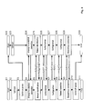
- FIG. 8 shows the conceptual sequence of the operations, where S 1 -S 11 represent the steps carried out in the device 50 , and S 22 -S 30 represent the steps carried out in the plug part 10 .
- the querying of information by the device 50 takes place, for example, in the manner of a service, and is indicated by an arrow denoted by S (service request) in FIG. 8 .
- the subsequent response by the plug part 10 is indicated in each case by an arrow denoted by R (response).
- the device 50 and the plug part 10 are configured in such a way, for example, that the device 50 contains only generic routines and is free of system-specific parameters, while the plug part 10 contains no device- or system-specific routines, but, rather, contains the parameters for same.
- step S 1 in FIG. 8 the device 50 carries out a self-test S 2 as the first operating phase, in which the functionality of the basic components of the device 50 is checked.
- the device subsequently switches on the power supply for the plug part 10 in step S 3 , which brings about start-up of the plug part 10 (step S 22 ).
- the intelligence system of the plug part 10 likewise carries out a self-test S 23 .
- the device 50 and the plug part 10 attempt to establish a communication relationship with one another in a subsequent step S 4 , S 24 , respectively.
- the device 50 goes into the identification phase S 5
- the plug part 10 goes into the identification phase S 25 .
- the device 50 requests the plug part 10 for its signature Sig 10 , in addition to other information such as the type and description of the cable tree, to be able to identify the plug part, and the device in turn transmits its signature Sig 50 , which permits the identification of the device 50 by the plug part 10 . It is thus known, on both sides, which is the mating part of a plug unit 1 or 10 .
- the plug part 10 is able to recognize which type of communication device is involved, such as a measuring device, a configuration device, etc., and in which operating mode the connected device 50 is to be used, for example, as an automation system in the regular operating mode, or possibly as a test system in a safe simulation mode which is not critical with regard to security.
- S 25 it may also be determined whether the cable-side plug part 10 matches the device-side mating part 1 , or whether mismating is possibly present, for example when two identical plug parts 10 having different pin or signal assignments are used. This verification may be carried out on the device side and/or on the cable side.
- the plug part 10 transfers an identification token (IDT) which corresponds to the type and operating mode.
- IDTT identification token
- the device 50 If the device 50 has an identification token, the device switches to the authorization phase S 6 .
- the device 50 makes available to the plug part 10 a list, AK (current components), the hardware and loaded software components currently used by the device, and their description.
- the plug part 10 now independently checks in step S 26 , based on the “table of permissible combinations of hardware and software versions” stored in the memory 13 , as to whether or not this information corresponds to the list AK supplied by the device 50 , and is thus a combination that is certified by an accredited test center.
- step S 26 the plug part 10 supplies an exclusive authorization token AT as a response, without which, in a manner inherent to the system, the connected device 50 cannot go into normal operation.
- the transmission of appropriate status messages may be provided via a communication medium, such as a display, if no AT is issued.
- the plug part 10 upon request by the device 50 and upon provision of the previously obtained exclusive authorization token AT, the plug part 10 delivers the configuration parameters KP which match the corresponding combination of hardware and software. These parameters have been stored beforehand in the list of the configuration parameters in the memory 13 of the plug part 10 . These include, but are not limited to, the following by way of example: definitive addresses to which the device 50 is addressable via bus systems, assignment of signal levels to the contact pins of the device-side plug unit 1 , also as a function of the field devices, filter parameters, magnification factors, etc., connected thereto. In the absence of the exclusive authorization token AT, the plug part 10 transmits no configuration data. Based on the received configuration data, the device 50 , on the other hand, is then capable of being dynamically configured.
- the device 50 goes into the last phase S 8 , the normal operation phase, and takes over its targeted task:
- the processing microprocessor 4 of the connected device 50 can terminate the communication relationship with the microprocessor 14 in the plug part 10 and switch off the feed to the cable-side intelligence system 20 .
- the microprocessor may also carry this out only later, for example when the cable-side intelligence system 20 is to be used for further, in particular safety-relevant, tasks.
- the processing microprocessor 4 of the connected device 50 is now able to go into normal operation for reading, processing, communicating with the higher-level communication network, and outputting signals.
- the device 50 may optionally store the information, which may possibly be necessary for the further processing upon being switched on again, in the plug part 10 in a nonvolatile manner.
- the connection is subsequently routinely discontinued in S 9 , S 29 , and the feed to the plug part 10 is switched off in S 10 .
- Networks such as those for automation technology and/or those found in automobiles, trains, or aircraft, may have extremely complex designs, for example when, due to the variety in the connected devices and/or the lack of appropriate standards, different cables must be used.
- the overall cabling is generally not set up using individual (single- or multi-wire) cables with a 1:1 relationship; rather, multiple cables and optionally also individual wires are combined into cable bundles (a cable tree) so that an n:m relationship results.
- These cable trees are often prefabricated, and are installed in the system as a unit at a suitable assembly time.
- peripheral devices for example, control signals for the control elements used as actuators and their check-back signals, as well as sensors
- This connectivity includes the absence of short circuits, the continuity of the connections, and the connection of the correct, corresponding end points.
- FIG. 9 shows one possible embodiment of a test apparatus.
- the device 50 has one or more mating parts 1 as connectors. During normal operation, a plug part 10 is inserted into a mating part 1 , so that the device 50 is connected via a cable tree 55 to a sensor or actuator 56 , for example.
- the test apparatus has a test unit 70 and a measuring device 60 .
- the test unit 70 includes one or more connectors 71 , at least one of which has the same design as a connector 1 of the device 50 .
- the plug part 10 is thus insertable into a connector 71 of the test unit 70 .
- the test unit also includes a test generator 72 and a communication master 73 .
- the test generator 72 is universal, in that it is at least capable of representing all signal sources and/or loads that are typical for the system family and/or product family to be tested.
- the test generator is typically configurable in such a way that it has only generic routines, and contains neither system- or device-specific information nor parameters, since these have already been stored in the cable-side plug parts 10 , for example during manufacture of the cable, and therefore are obtained from that location.
- the measuring device 60 has a mobile design, and includes a measuring unit 62 and a communication slave 63 .
- the measuring device 60 is configurable in such a way that it contains only generic routines, and contains no parameters which define the test, since these are provided by the test unit 70 .
- the communication master 73 and the communication slave 63 are set up for establishing a communication relationship 65 , which preferably takes place wirelessly.
- test unit 70 is connected to the cable tree 55 instead of to the device 50 .
- the connectivity of the cable tree 55 and/or the functionality of the other connected devices is/are checked, using the measuring device 60 together with the test unit 70 .
- test apparatus made up of the test unit 60 and the measuring device 70 may be universalized so that they form units having the same design, and which in each case may take over the role of either the measuring device or of the test unit, depending on the configuration.
- test apparatus may be designed in such a way that the assignment of the master or slave functionality of the two devices 60 , 70 is interactively selectable.
- the connected device 50 itself may also take over the role of the test unit 70 , of the measuring device 60 , or partial roles thereof.
- FIGS. 10 a and 10 b show an example of a sequence for testing a network.
- S 60 -S 67 denote the steps that are carried out in the measuring device 60
- S 70 -S 82 denote the steps that are carried out in the test unit 70
- S 40 -S 47 denote the steps that are carried out in the plug part 10 .
- the transition from the last step in FIG. 10 a to the next step in FIG. 10 b is indicated in each case by the encircled letters A, B, and C.
- the querying of information by the test unit 70 which is delivered by the measuring device 60 and by the plug part 10 takes place, for example, in the manner of a service, and is indicated by an arrow denoted by S (service request) in FIGS. 10 a and 10 b .
- S service request
- R response by the measuring device 60 or the plug part 10 is in each case indicated by an arrow denoted by R (response).
- the memory 13 of the plug part 10 contains, among other things, information which defines how the plug elements of the plug part 10 , which are present as pins, for example, are associated with other plug elements for other plug parts 10 via the cable tree 55 .
- This information may be provided as follows, for example:
- a network list is generated directly from CAD. This network list completely describes which connection from which pin of a plug to which pin of another plug must be achieved at a different location. (The particular plug is implemented on a device 50 by the plug part 10 or the mating part 1 .)
- a plug-based list is created from the network list by regrouping the information contained therein.
- This plug-based list together with at least a plug-specific signature is programmed into the nonvolatile memory 13 of the plug part 10 , typically during prefabrication of the cable tree.
- the location of the plug within the system, the manner of testing the connection, and other relevant information are likewise stored.
- Self-test phase When the test unit 70 is switched on (step S 70 in FIG. 10 a ), it conducts a self-test (step S 71 ), and in principle is then ready for carrying out testing operations.
- the actual testing of the cable tree 55 of a system begins with the initial plugging in of a first plug part 10 into the test unit 70 .
- the test unit 70 switches on the power supply for the cable-side intelligence system of the plug part 10 (step S 72 ).
- step S 42 and S 73 After the self-test of the intelligence system 20 of the cable-side plug part 10 , the latter takes part in the establishment of communication with the test unit 70 (steps S 42 and S 73 ), and communication takes place.
- Identification phase The test unit 70 and the intelligence system 20 of the plug part 10 exchange signatures with one another (steps S 43 and S 74 ).
- the intelligence system 20 of the plug part 10 recognizes the device as an appropriate test unit 70 based on its signature, and authorizes the device to access its list of test sequences. This is signaled to the test unit 70 by an exclusive test token (denoted by reference character TT in FIG. 10 a ) (steps S 44 and S 75 ).
- the measuring device 60 carries out a self-test (steps S 60 and S 61 ), establishes a connection with the test unit 70 (steps S 62 and S 73 ), and exchanges its signature with the test unit 70 (steps S 63 and S 74 ).
- the subsequent authorization phase between the devices 60 and 70 proceeds in the same way as between the test unit 70 and the plug part 10 (steps S 64 and S 75 ).
- the test unit 70 obtains a measurement token (denoted by reference character MT in FIG. 10 a ), which the test unit uses in each case for authorization for service requests to the measuring device 60 .
- the test unit 70 has the test token TT, and may thus request test sequences from the intelligence system 20 of the cable-side plug part 10 . Without the test token TT, the intelligence system 20 of the plug part 10 delivers no test sequence instructions. The intelligence system 20 of the plug part 10 now delivers a (first) test sequence as a response to a test sequence request.
- the plug part 10 in each case accordingly carries out the following substeps: checking the TT, reading the first or next test sequence from a table, and responding to a service request S(TT) by the test unit 70 .
- Each test sequence during step S 76 includes a configuration phase and a test phase, each having the following substeps:
- the measuring sequence during step S 65 includes a configuration phase and a measurement phase, each having the following substeps:
- the testing of a plug part 10 thus terminates when the test unit 70 no longer receives a test sequence instruction, but instead receives a message containing an abort criterion.
- test unit 70 exits the intelligence system 20 of the plug part 10 in order to quit the test sequence control.
- the test token TT issued during the authorization phase thus loses its validity.
- the communication relationship with the cable-side plug part is also terminated (steps S 77 and S 46 ), but not the communication relationship with the measuring device 60 .
- the plug part 10 which is inserted into the test unit 70 may subsequently be removed from the test unit 70 and inserted into the device 50 .
- a next plug part 10 may subsequently be inserted into the test unit 70 , and the procedure starts over with step S 40 for the new plug part 10 (iteration via the plug: external iterative loop) upon start-up, then the self-test of the cable-side plug part 10 , followed by the establishment of communication, the identification phase, and the authorization phase, and subsequently the execution of the test sequences, and so forth.
- the cable tree 55 has plug parts which contain no intelligence system that is like the intelligence system 20 of the plug part 10 , the wires in question must be tested in the conventional manner.
- the cable tree 55 of a system is subsequently tested.
- the measuring device 70 Upon exiting the external iterative loop during step S 78 , the measuring device 70 is also returned to its initial state, and the communication relationship between the measuring device 70 and the test unit 60 is discontinued (steps S 66 and S 79 ).
- the test is documented, for example, by printing out a test report (step S 80 ).
- An intelligent plug part may be provided which is implementable in automation systems or similar systems for plug-in connections of cable trees to devices, and which is able to check the plausibility of the correctness of the subsystem wiring, to control test sequences for measuring even individual cable wires, to check required device configurations in hardware and software, and to enforce the correctness of the configuration by securely blocking the normal operating mode.
- the plug part is able to describe the requirements for the sources and loads to be connected.
- At least semi-autonomous functions may be assigned to the plug part according to the invention on account of its intelligence system. It is thus possible to carry out more extensive testing than is customary.
- Information in particular information that is already present in electronic form, may be stored in the memory of the plug part according to the invention and thus utilized.
- CAD tools Electronic CAD, for example
- circuit diagrams, terminal diagrams, and the like which describe the functionality, and which are thus available in electronic form.
- the task of the cable trees, and which devices are to be connected to which other devices, and how, may also be provided as a network list.
- the characteristic properties of the devices that are used may be extracted from device descriptions and device data sheets, and electronically displayed.
- the plug part described here forms an intelligence system which is located on site and provides the necessary information, processing options, and communication capability, for example:
Applications Claiming Priority (4)
| Application Number | Priority Date | Filing Date | Title |
|---|---|---|---|
| CH01649/12 | 2012-09-10 | ||
| CH01649/12A CH706927A1 (de) | 2012-09-10 | 2012-09-10 | Steckteil zur Bildung einer Steckverbindung. |
| CH1649/12 | 2012-09-10 | ||
| PCT/EP2013/068747 WO2014037586A2 (de) | 2012-09-10 | 2013-09-10 | Steckteil zur bildung einer steckverbindung |
Publications (2)
| Publication Number | Publication Date |
|---|---|
| US20150213291A1 US20150213291A1 (en) | 2015-07-30 |
| US9613230B2 true US9613230B2 (en) | 2017-04-04 |
Family
ID=46851227
Family Applications (1)
| Application Number | Title | Priority Date | Filing Date |
|---|---|---|---|
| US14/426,530 Active US9613230B2 (en) | 2012-09-10 | 2013-09-10 | Plug part for forming a plug-in connection |
Country Status (8)
| Country | Link |
|---|---|
| US (1) | US9613230B2 (de) |
| EP (1) | EP2893599B1 (de) |
| CN (1) | CN104620447B (de) |
| CH (1) | CH706927A1 (de) |
| EA (1) | EA031491B1 (de) |
| HR (1) | HRP20220067T1 (de) |
| IN (1) | IN2015KN00536A (de) |
| WO (1) | WO2014037586A2 (de) |
Families Citing this family (9)
| Publication number | Priority date | Publication date | Assignee | Title |
|---|---|---|---|---|
| DE102015105262A1 (de) * | 2015-04-08 | 2016-10-13 | Harting Electric Gmbh & Co. Kg | Kapazitives Sensormodul für einen Steckverbinder |
| EP3229033A1 (de) * | 2016-04-08 | 2017-10-11 | ABB Schweiz AG | Prüfstand, der mit ein- und ausgangssteckdosen vom typ rj45 ausgestattet ist |
| EP3229034B1 (de) | 2016-04-08 | 2023-04-26 | TE Connectivity Solutions GmbH | Prüfstand mit faraday-käfig |
| DE102018130509A1 (de) * | 2018-11-30 | 2020-06-04 | Harting Electric Gmbh & Co. Kg | Messeinrichtung für Betriebszustand |
| CN112186398B (zh) * | 2019-06-13 | 2022-11-08 | 佛山市顺德区美的电热电器制造有限公司 | 连接装置、家电设备、家电设备的信号处理方法及装置 |
| CN113450865B (zh) * | 2020-03-26 | 2022-05-20 | 长鑫存储技术有限公司 | 存储器测试系统及其测试方法 |
| DE102022123991A1 (de) * | 2022-09-19 | 2024-03-21 | Knorr-Bremse Systeme für Schienenfahrzeuge GmbH | Anordnung einer Systemkomponente eines Schienenfahrzeugs mit intelligenter Steckverbindung (Smart Plug) und ein Schienenfahrzeug mit einer solchen Anordnung |
| DE102022124490A1 (de) | 2022-09-23 | 2024-03-28 | Harting Electric Stiftung & Co. Kg | Steckverbindersystem |
| CN116387896B (zh) * | 2023-06-05 | 2023-08-04 | 山东讯凌信息技术有限公司 | 一种用于网络安全防护的自动切断装置 |
Citations (21)
| Publication number | Priority date | Publication date | Assignee | Title |
|---|---|---|---|---|
| GB2264843A (en) | 1992-02-28 | 1993-09-08 | Texas Instruments Ltd | An interface device for coupling a host device to a computer network |
| WO1999018496A1 (en) | 1997-10-07 | 1999-04-15 | Electronics Development Corporation | Transducer assembly with smart connector |
| DE19812901A1 (de) | 1998-03-18 | 1999-09-23 | Bb Data Inf & Komm Syst Gmbh | Computernetz mit Daten- oder Kommunikationsendsystemen |
| US20030073343A1 (en) | 2001-10-16 | 2003-04-17 | Adam Belesimo | Testing assembly and method for identifying network circuits |
| US20030100297A1 (en) * | 2001-11-27 | 2003-05-29 | Riordan Kenneth B. | Method of software configuration assurance in programmable terminal devices |
| DE10351773A1 (de) | 2002-11-15 | 2004-06-09 | Tokyo Communication Equipment mfg. Co.Ltd. | Verteilungssystem |
| US20040123127A1 (en) * | 2002-12-18 | 2004-06-24 | M-Systems Flash Disk Pioneers, Ltd. | System and method for securing portable data |
| US20050222718A1 (en) * | 2004-03-30 | 2005-10-06 | Scania Cv Ab (Publ) | Data access to electronic control units |
| DE102005002472A1 (de) | 2005-01-18 | 2006-07-27 | Maschinenfabrik Rieter Ag | Textilmaschine und Softwareschutzvorrichtung für eine Textilmaschine |
| US20070103277A1 (en) | 2005-11-09 | 2007-05-10 | Honeywell International, Inc. | Security system enhancement device key |
| DE202006015797U1 (de) | 2006-10-12 | 2008-02-14 | Phoenix Contact Gmbh & Co. Kg | Parametrierung einer intelligenten Einheit über Spannungsversorgungseinrichtung |
| US20090094597A1 (en) * | 2007-10-04 | 2009-04-09 | Memory Experts International Inc. | Portable firmware device |
| US20090183256A1 (en) * | 2008-01-15 | 2009-07-16 | Samsung Electronics Co., Ltd. | Method and apparatus for authorizing host to access portable storage device |
| EP1818859B1 (de) | 2006-02-09 | 2009-12-09 | Hitachi, Ltd. | Kabelbaum mit RFID-Etiketten an Steckern des Kabelbaums und Kabelbaummontageverfahren |
| US7712131B1 (en) * | 2005-02-09 | 2010-05-04 | David Lethe | Method and apparatus for storage and use of diagnostic software using removeable secure solid-state memory |
| US20110043371A1 (en) | 2009-08-21 | 2011-02-24 | Michael German | Systems, Equipment and Methods for Automatically Tracking Cable Connections and for Identifying Work Area Devices and Related Methods of Operating Communications Networks |
| US20110144823A1 (en) | 2009-07-28 | 2011-06-16 | Michael Muller | Sequential Charging of Multiple Electric Vehicles |
| US20120051735A1 (en) * | 2010-08-26 | 2012-03-01 | Cisco Technology, Inc. | Scalable high speed gigabit active bundle link and tester |
| US20120133490A1 (en) | 2006-10-31 | 2012-05-31 | Corning Incorporated | Communications Between Multiple Radio Frequency Identification (RFID) Connected Tags And One Or More Devices, And Related Systems And Methods |
| US20130046987A1 (en) * | 2011-08-15 | 2013-02-21 | Bank Of America Corporation | Apparatus and Method for Performing End-to-End Encryption |
| US20130117854A1 (en) * | 2011-11-09 | 2013-05-09 | Douglas Britton | System and Method for Bidirectional Trust Between Downloaded Applications and Mobile Devices Including a Secure Charger and Malware Scanner |
Family Cites Families (1)
| Publication number | Priority date | Publication date | Assignee | Title |
|---|---|---|---|---|
| DE102007029423B4 (de) * | 2007-06-26 | 2009-09-03 | Sick Ag | Steuerungssystem |
-
2012
- 2012-09-10 CH CH01649/12A patent/CH706927A1/de not_active Application Discontinuation
-
2013
- 2013-09-10 US US14/426,530 patent/US9613230B2/en active Active
- 2013-09-10 HR HRP20220067TT patent/HRP20220067T1/hr unknown
- 2013-09-10 IN IN536KON2015 patent/IN2015KN00536A/en unknown
- 2013-09-10 WO PCT/EP2013/068747 patent/WO2014037586A2/de active Application Filing
- 2013-09-10 EP EP13763027.3A patent/EP2893599B1/de active Active
- 2013-09-10 EA EA201590538A patent/EA031491B1/ru not_active IP Right Cessation
- 2013-09-10 CN CN201380047113.0A patent/CN104620447B/zh active Active
Patent Citations (23)
| Publication number | Priority date | Publication date | Assignee | Title |
|---|---|---|---|---|
| GB2264843A (en) | 1992-02-28 | 1993-09-08 | Texas Instruments Ltd | An interface device for coupling a host device to a computer network |
| WO1999018496A1 (en) | 1997-10-07 | 1999-04-15 | Electronics Development Corporation | Transducer assembly with smart connector |
| DE19812901A1 (de) | 1998-03-18 | 1999-09-23 | Bb Data Inf & Komm Syst Gmbh | Computernetz mit Daten- oder Kommunikationsendsystemen |
| US20030073343A1 (en) | 2001-10-16 | 2003-04-17 | Adam Belesimo | Testing assembly and method for identifying network circuits |
| US7014500B2 (en) | 2001-10-16 | 2006-03-21 | Adam Belesimo | Testing assembly and method for identifying network circuits |
| US20030100297A1 (en) * | 2001-11-27 | 2003-05-29 | Riordan Kenneth B. | Method of software configuration assurance in programmable terminal devices |
| DE10351773A1 (de) | 2002-11-15 | 2004-06-09 | Tokyo Communication Equipment mfg. Co.Ltd. | Verteilungssystem |
| US20040117515A1 (en) | 2002-11-15 | 2004-06-17 | Masuyuki Sago | Distributing system |
| US20040123127A1 (en) * | 2002-12-18 | 2004-06-24 | M-Systems Flash Disk Pioneers, Ltd. | System and method for securing portable data |
| US20050222718A1 (en) * | 2004-03-30 | 2005-10-06 | Scania Cv Ab (Publ) | Data access to electronic control units |
| DE102005002472A1 (de) | 2005-01-18 | 2006-07-27 | Maschinenfabrik Rieter Ag | Textilmaschine und Softwareschutzvorrichtung für eine Textilmaschine |
| US7712131B1 (en) * | 2005-02-09 | 2010-05-04 | David Lethe | Method and apparatus for storage and use of diagnostic software using removeable secure solid-state memory |
| US20070103277A1 (en) | 2005-11-09 | 2007-05-10 | Honeywell International, Inc. | Security system enhancement device key |
| EP1818859B1 (de) | 2006-02-09 | 2009-12-09 | Hitachi, Ltd. | Kabelbaum mit RFID-Etiketten an Steckern des Kabelbaums und Kabelbaummontageverfahren |
| DE202006015797U1 (de) | 2006-10-12 | 2008-02-14 | Phoenix Contact Gmbh & Co. Kg | Parametrierung einer intelligenten Einheit über Spannungsversorgungseinrichtung |
| US20120133490A1 (en) | 2006-10-31 | 2012-05-31 | Corning Incorporated | Communications Between Multiple Radio Frequency Identification (RFID) Connected Tags And One Or More Devices, And Related Systems And Methods |
| US20090094597A1 (en) * | 2007-10-04 | 2009-04-09 | Memory Experts International Inc. | Portable firmware device |
| US20090183256A1 (en) * | 2008-01-15 | 2009-07-16 | Samsung Electronics Co., Ltd. | Method and apparatus for authorizing host to access portable storage device |
| US20110144823A1 (en) | 2009-07-28 | 2011-06-16 | Michael Muller | Sequential Charging of Multiple Electric Vehicles |
| US20110043371A1 (en) | 2009-08-21 | 2011-02-24 | Michael German | Systems, Equipment and Methods for Automatically Tracking Cable Connections and for Identifying Work Area Devices and Related Methods of Operating Communications Networks |
| US20120051735A1 (en) * | 2010-08-26 | 2012-03-01 | Cisco Technology, Inc. | Scalable high speed gigabit active bundle link and tester |
| US20130046987A1 (en) * | 2011-08-15 | 2013-02-21 | Bank Of America Corporation | Apparatus and Method for Performing End-to-End Encryption |
| US20130117854A1 (en) * | 2011-11-09 | 2013-05-09 | Douglas Britton | System and Method for Bidirectional Trust Between Downloaded Applications and Mobile Devices Including a Secure Charger and Malware Scanner |
Non-Patent Citations (2)
| Title |
|---|
| Chinese Office Action with Search Report dated Sep. 5, 2016 issued in corresponding CN Application No. 201380047113.0 with English translation. |
| International Search Report dated May 21, 2014 issued in corresponding International patent application No. PCT/EP2013/068747. |
Also Published As
| Publication number | Publication date |
|---|---|
| EP2893599B1 (de) | 2021-12-01 |
| WO2014037586A2 (de) | 2014-03-13 |
| CH706927A1 (de) | 2014-03-14 |
| EA031491B1 (ru) | 2019-01-31 |
| EP2893599A2 (de) | 2015-07-15 |
| CN104620447A (zh) | 2015-05-13 |
| US20150213291A1 (en) | 2015-07-30 |
| CN104620447B (zh) | 2018-03-06 |
| EA201590538A1 (ru) | 2015-06-30 |
| HRP20220067T1 (hr) | 2022-04-15 |
| IN2015KN00536A (de) | 2015-07-17 |
| WO2014037586A3 (de) | 2014-07-03 |
Similar Documents
| Publication | Publication Date | Title |
|---|---|---|
| US9613230B2 (en) | Plug part for forming a plug-in connection | |
| CN100533315C (zh) | 保险控制器 | |
| US8977851B2 (en) | Removable security modules and related methods | |
| US10503680B2 (en) | Method for operating an automation device | |
| US10432754B2 (en) | Safety networking protocol and method | |
| CN106020136B (zh) | 用于定义槽位地址的方法及系统 | |
| US10431032B2 (en) | Method and arrangement for detecting a quantity of plug cycles of a plug connection component | |
| CN105122156B (zh) | 一种电气接口模块 | |
| US20200064819A1 (en) | Systems and methods to implement a safety state environment | |
| CN101826966B (zh) | 通信网络和转换器模块 | |
| JP6996893B2 (ja) | バスでフィールドデバイスに給電してフィールドデバイスと通信する携帯型フィールド保守ツール | |
| JP2011528478A (ja) | ネットワーク保護機構を有する改良されたフィールド装置インターフェイス | |
| JP2015156786A (ja) | 産業用制御システムに関する安全な電源 | |
| CN109375599A (zh) | 电气自动控制系统及控制方法 | |
| KR101575451B1 (ko) | 차량 사양 구성 확인 방법 | |
| JP5351251B2 (ja) | 電力出口とデバイスとの効率的な関連付けのためのシステム及び方法 | |
| JP7275940B2 (ja) | 制御プログラムおよび方法 | |
| CA2998640A1 (en) | Safety networking protocol and method | |
| CN102362299B (zh) | 用于编码器自动重置的设备和方法 | |
| CN105653289B (zh) | 车载软件控制管理装置及其应用方法 | |
| CN106415514B (zh) | 一种电接口模块 | |
| CN105205363A (zh) | 一种水表信息安全管理模块 | |
| US10917252B2 (en) | Implementing a diagnosis capability of a nonautomotive controller in an automotive environment | |
| CN113783747A (zh) | 通信设备、识别所使用的网络协议的方法和现场设备 | |
| CN113728279A (zh) | 用于改变自动化系统的控制软件的方法 |
Legal Events
| Date | Code | Title | Description |
|---|---|---|---|
| AS | Assignment |
Owner name: SELECTRON SYSTEMS AG, SWITZERLAND Free format text: ASSIGNMENT OF ASSIGNORS INTEREST;ASSIGNORS:GUT, MAX;RIEDEL, BERND;REEL/FRAME:035102/0949 Effective date: 20131008 |
|
| STCF | Information on status: patent grant |
Free format text: PATENTED CASE |
|
| MAFP | Maintenance fee payment |
Free format text: PAYMENT OF MAINTENANCE FEE, 4TH YEAR, LARGE ENTITY (ORIGINAL EVENT CODE: M1551); ENTITY STATUS OF PATENT OWNER: LARGE ENTITY Year of fee payment: 4 |