US9575022B2 - Electronic indicator for monitoring efficacy of a cleaning cycle - Google Patents
Electronic indicator for monitoring efficacy of a cleaning cycle Download PDFInfo
- Publication number
- US9575022B2 US9575022B2 US14/429,719 US201314429719A US9575022B2 US 9575022 B2 US9575022 B2 US 9575022B2 US 201314429719 A US201314429719 A US 201314429719A US 9575022 B2 US9575022 B2 US 9575022B2
- Authority
- US
- United States
- Prior art keywords
- electronic indicator
- wash
- electrical characteristic
- sensor
- electronic
- Prior art date
- Legal status (The legal status is an assumption and is not a legal conclusion. Google has not performed a legal analysis and makes no representation as to the accuracy of the status listed.)
- Active, expires
Links
- 238000004140 cleaning Methods 0.000 title claims abstract description 126
- 238000012544 monitoring process Methods 0.000 title description 10
- 239000002689 soil Substances 0.000 claims abstract description 235
- 230000008859 change Effects 0.000 claims abstract description 29
- 230000004888 barrier function Effects 0.000 claims description 151
- 238000000034 method Methods 0.000 claims description 42
- 230000004044 response Effects 0.000 claims description 36
- 238000005259 measurement Methods 0.000 claims description 26
- 239000003989 dielectric material Substances 0.000 claims description 21
- 231100000136 action limit Toxicity 0.000 claims description 9
- 239000004020 conductor Substances 0.000 claims description 9
- 230000009471 action Effects 0.000 claims description 7
- 239000010410 layer Substances 0.000 description 125
- 238000000576 coating method Methods 0.000 description 41
- 239000011248 coating agent Substances 0.000 description 39
- XLYOFNOQVPJJNP-UHFFFAOYSA-N water Substances O XLYOFNOQVPJJNP-UHFFFAOYSA-N 0.000 description 38
- 238000004659 sterilization and disinfection Methods 0.000 description 29
- 229910052751 metal Inorganic materials 0.000 description 26
- 239000002184 metal Substances 0.000 description 26
- 230000008569 process Effects 0.000 description 20
- 230000007423 decrease Effects 0.000 description 18
- 239000000463 material Substances 0.000 description 14
- 230000035945 sensitivity Effects 0.000 description 13
- 238000012360 testing method Methods 0.000 description 12
- 239000000203 mixture Substances 0.000 description 10
- RYGMFSIKBFXOCR-UHFFFAOYSA-N Copper Chemical compound [Cu] RYGMFSIKBFXOCR-UHFFFAOYSA-N 0.000 description 9
- 229910052802 copper Inorganic materials 0.000 description 9
- 239000010949 copper Substances 0.000 description 9
- 230000005684 electric field Effects 0.000 description 8
- 229920001721 polyimide Polymers 0.000 description 8
- 230000006870 function Effects 0.000 description 7
- 229920006395 saturated elastomer Polymers 0.000 description 7
- IBIKHMZPHNKTHM-RDTXWAMCSA-N merck compound 25 Chemical compound C1C[C@@H](C(O)=O)[C@H](O)CN1C(C1=C(F)C=CC=C11)=NN1C(=O)C1=C(Cl)C=CC=C1C1CC1 IBIKHMZPHNKTHM-RDTXWAMCSA-N 0.000 description 6
- -1 polytetrafluoroethylene Polymers 0.000 description 6
- 238000005406 washing Methods 0.000 description 6
- 239000003990 capacitor Substances 0.000 description 5
- 230000008021 deposition Effects 0.000 description 5
- 239000003599 detergent Substances 0.000 description 5
- KDLHZDBZIXYQEI-UHFFFAOYSA-N Palladium Chemical compound [Pd] KDLHZDBZIXYQEI-UHFFFAOYSA-N 0.000 description 4
- 239000004642 Polyimide Substances 0.000 description 4
- 239000011230 binding agent Substances 0.000 description 4
- 229910010272 inorganic material Inorganic materials 0.000 description 4
- 239000011147 inorganic material Substances 0.000 description 4
- 238000012423 maintenance Methods 0.000 description 4
- BASFCYQUMIYNBI-UHFFFAOYSA-N platinum Chemical compound [Pt] BASFCYQUMIYNBI-UHFFFAOYSA-N 0.000 description 4
- 239000000126 substance Substances 0.000 description 4
- 239000012491 analyte Substances 0.000 description 3
- 238000005202 decontamination Methods 0.000 description 3
- 238000001035 drying Methods 0.000 description 3
- 230000000694 effects Effects 0.000 description 3
- 230000002255 enzymatic effect Effects 0.000 description 3
- 239000012530 fluid Substances 0.000 description 3
- 150000002739 metals Chemical class 0.000 description 3
- 229920000728 polyester Polymers 0.000 description 3
- 229920001296 polysiloxane Polymers 0.000 description 3
- 230000009467 reduction Effects 0.000 description 3
- 238000001223 reverse osmosis Methods 0.000 description 3
- 239000002904 solvent Substances 0.000 description 3
- 239000008223 sterile water Substances 0.000 description 3
- 239000000758 substrate Substances 0.000 description 3
- 238000011179 visual inspection Methods 0.000 description 3
- 229920002943 EPDM rubber Polymers 0.000 description 2
- 102000004190 Enzymes Human genes 0.000 description 2
- 108090000790 Enzymes Proteins 0.000 description 2
- 239000004593 Epoxy Substances 0.000 description 2
- 235000009161 Espostoa lanata Nutrition 0.000 description 2
- 240000001624 Espostoa lanata Species 0.000 description 2
- 239000004812 Fluorinated ethylene propylene Substances 0.000 description 2
- BQCADISMDOOEFD-UHFFFAOYSA-N Silver Chemical compound [Ag] BQCADISMDOOEFD-UHFFFAOYSA-N 0.000 description 2
- ATJFFYVFTNAWJD-UHFFFAOYSA-N Tin Chemical compound [Sn] ATJFFYVFTNAWJD-UHFFFAOYSA-N 0.000 description 2
- 239000000853 adhesive Substances 0.000 description 2
- 230000001070 adhesive effect Effects 0.000 description 2
- 239000012790 adhesive layer Substances 0.000 description 2
- 239000000956 alloy Substances 0.000 description 2
- 229910045601 alloy Inorganic materials 0.000 description 2
- 229910052782 aluminium Inorganic materials 0.000 description 2
- XAGFODPZIPBFFR-UHFFFAOYSA-N aluminium Chemical compound [Al] XAGFODPZIPBFFR-UHFFFAOYSA-N 0.000 description 2
- 239000000919 ceramic Substances 0.000 description 2
- 229910010293 ceramic material Inorganic materials 0.000 description 2
- 239000012459 cleaning agent Substances 0.000 description 2
- 238000010276 construction Methods 0.000 description 2
- 238000013461 design Methods 0.000 description 2
- 230000000249 desinfective effect Effects 0.000 description 2
- 238000010586 diagram Methods 0.000 description 2
- 239000000975 dye Substances 0.000 description 2
- 239000011521 glass Substances 0.000 description 2
- PCHJSUWPFVWCPO-UHFFFAOYSA-N gold Chemical compound [Au] PCHJSUWPFVWCPO-UHFFFAOYSA-N 0.000 description 2
- 229910052737 gold Inorganic materials 0.000 description 2
- 239000010931 gold Substances 0.000 description 2
- 238000011065 in-situ storage Methods 0.000 description 2
- AMGQUBHHOARCQH-UHFFFAOYSA-N indium;oxotin Chemical compound [In].[Sn]=O AMGQUBHHOARCQH-UHFFFAOYSA-N 0.000 description 2
- 229910044991 metal oxide Inorganic materials 0.000 description 2
- 150000004706 metal oxides Chemical class 0.000 description 2
- 244000005700 microbiome Species 0.000 description 2
- 239000011368 organic material Substances 0.000 description 2
- 238000004806 packaging method and process Methods 0.000 description 2
- 238000007427 paired t-test Methods 0.000 description 2
- 229910052763 palladium Inorganic materials 0.000 description 2
- 229920009441 perflouroethylene propylene Polymers 0.000 description 2
- 230000035699 permeability Effects 0.000 description 2
- 229910052697 platinum Inorganic materials 0.000 description 2
- 229920003223 poly(pyromellitimide-1,4-diphenyl ether) Polymers 0.000 description 2
- 229920000139 polyethylene terephthalate Polymers 0.000 description 2
- 239000005020 polyethylene terephthalate Substances 0.000 description 2
- 229920001343 polytetrafluoroethylene Polymers 0.000 description 2
- 239000004810 polytetrafluoroethylene Substances 0.000 description 2
- 229920002451 polyvinyl alcohol Polymers 0.000 description 2
- 239000000523 sample Substances 0.000 description 2
- 229910052709 silver Inorganic materials 0.000 description 2
- 239000004332 silver Substances 0.000 description 2
- 241000894006 Bacteria Species 0.000 description 1
- LFQSCWFLJHTTHZ-UHFFFAOYSA-N Ethanol Chemical compound CCO LFQSCWFLJHTTHZ-UHFFFAOYSA-N 0.000 description 1
- 102000001554 Hemoglobins Human genes 0.000 description 1
- 108010054147 Hemoglobins Proteins 0.000 description 1
- 244000043261 Hevea brasiliensis Species 0.000 description 1
- 239000004962 Polyamide-imide Substances 0.000 description 1
- 239000004698 Polyethylene Substances 0.000 description 1
- 229920002367 Polyisobutene Polymers 0.000 description 1
- 239000004734 Polyphenylene sulfide Substances 0.000 description 1
- 239000004743 Polypropylene Substances 0.000 description 1
- 229920002396 Polyurea Polymers 0.000 description 1
- 239000004820 Pressure-sensitive adhesive Substances 0.000 description 1
- VYPSYNLAJGMNEJ-UHFFFAOYSA-N Silicium dioxide Chemical compound O=[Si]=O VYPSYNLAJGMNEJ-UHFFFAOYSA-N 0.000 description 1
- GWEVSGVZZGPLCZ-UHFFFAOYSA-N Titan oxide Chemical compound O=[Ti]=O GWEVSGVZZGPLCZ-UHFFFAOYSA-N 0.000 description 1
- WGLPBDUCMAPZCE-UHFFFAOYSA-N Trioxochromium Chemical compound O=[Cr](=O)=O WGLPBDUCMAPZCE-UHFFFAOYSA-N 0.000 description 1
- 241000700605 Viruses Species 0.000 description 1
- XHCLAFWTIXFWPH-UHFFFAOYSA-N [O-2].[O-2].[O-2].[O-2].[O-2].[V+5].[V+5] Chemical compound [O-2].[O-2].[O-2].[O-2].[O-2].[V+5].[V+5] XHCLAFWTIXFWPH-UHFFFAOYSA-N 0.000 description 1
- 239000002253 acid Substances 0.000 description 1
- 238000013019 agitation Methods 0.000 description 1
- 239000003570 air Substances 0.000 description 1
- 238000013459 approach Methods 0.000 description 1
- 230000008901 benefit Effects 0.000 description 1
- 229920005549 butyl rubber Polymers 0.000 description 1
- 238000004364 calculation method Methods 0.000 description 1
- 150000001720 carbohydrates Chemical class 0.000 description 1
- 229910000423 chromium oxide Inorganic materials 0.000 description 1
- 239000002131 composite material Substances 0.000 description 1
- 230000003588 decontaminative effect Effects 0.000 description 1
- 230000003247 decreasing effect Effects 0.000 description 1
- 239000000645 desinfectant Substances 0.000 description 1
- 238000003618 dip coating Methods 0.000 description 1
- 239000007772 electrode material Substances 0.000 description 1
- 230000007613 environmental effect Effects 0.000 description 1
- 229920006334 epoxy coating Polymers 0.000 description 1
- 125000003700 epoxy group Chemical group 0.000 description 1
- HQQADJVZYDDRJT-UHFFFAOYSA-N ethene;prop-1-ene Chemical group C=C.CC=C HQQADJVZYDDRJT-UHFFFAOYSA-N 0.000 description 1
- 238000002474 experimental method Methods 0.000 description 1
- 244000053095 fungal pathogen Species 0.000 description 1
- 230000036541 health Effects 0.000 description 1
- 239000007970 homogeneous dispersion Substances 0.000 description 1
- 208000015181 infectious disease Diseases 0.000 description 1
- 238000007641 inkjet printing Methods 0.000 description 1
- 238000009413 insulation Methods 0.000 description 1
- 244000000010 microbial pathogen Species 0.000 description 1
- 238000012986 modification Methods 0.000 description 1
- 230000004048 modification Effects 0.000 description 1
- 229920003052 natural elastomer Polymers 0.000 description 1
- 229920001194 natural rubber Polymers 0.000 description 1
- 102000039446 nucleic acids Human genes 0.000 description 1
- 108020004707 nucleic acids Proteins 0.000 description 1
- 150000007523 nucleic acids Chemical class 0.000 description 1
- 239000002773 nucleotide Substances 0.000 description 1
- 125000003729 nucleotide group Chemical group 0.000 description 1
- 230000008520 organization Effects 0.000 description 1
- TWNQGVIAIRXVLR-UHFFFAOYSA-N oxo(oxoalumanyloxy)alumane Chemical compound O=[Al]O[Al]=O TWNQGVIAIRXVLR-UHFFFAOYSA-N 0.000 description 1
- BPUBBGLMJRNUCC-UHFFFAOYSA-N oxygen(2-);tantalum(5+) Chemical compound [O-2].[O-2].[O-2].[O-2].[O-2].[Ta+5].[Ta+5] BPUBBGLMJRNUCC-UHFFFAOYSA-N 0.000 description 1
- RVTZCBVAJQQJTK-UHFFFAOYSA-N oxygen(2-);zirconium(4+) Chemical compound [O-2].[O-2].[Zr+4] RVTZCBVAJQQJTK-UHFFFAOYSA-N 0.000 description 1
- 229920003023 plastic Polymers 0.000 description 1
- 239000004033 plastic Substances 0.000 description 1
- 229920002493 poly(chlorotrifluoroethylene) Polymers 0.000 description 1
- 229920003207 poly(ethylene-2,6-naphthalate) Polymers 0.000 description 1
- 229920000058 polyacrylate Polymers 0.000 description 1
- 229920002312 polyamide-imide Polymers 0.000 description 1
- 239000004417 polycarbonate Substances 0.000 description 1
- 229920000515 polycarbonate Polymers 0.000 description 1
- 229920000647 polyepoxide Polymers 0.000 description 1
- 229920000573 polyethylene Polymers 0.000 description 1
- 239000011112 polyethylene naphthalate Substances 0.000 description 1
- 229920000069 polyphenylene sulfide Polymers 0.000 description 1
- 229920001155 polypropylene Polymers 0.000 description 1
- 229920002635 polyurethane Polymers 0.000 description 1
- 239000004814 polyurethane Substances 0.000 description 1
- 239000004800 polyvinyl chloride Substances 0.000 description 1
- 239000005033 polyvinylidene chloride Substances 0.000 description 1
- 238000012545 processing Methods 0.000 description 1
- 102000004169 proteins and genes Human genes 0.000 description 1
- 108090000623 proteins and genes Proteins 0.000 description 1
- 239000008213 purified water Substances 0.000 description 1
- 238000007650 screen-printing Methods 0.000 description 1
- 229910052814 silicon oxide Inorganic materials 0.000 description 1
- 229920002379 silicone rubber Polymers 0.000 description 1
- 239000004945 silicone rubber Substances 0.000 description 1
- 238000005507 spraying Methods 0.000 description 1
- 238000003756 stirring Methods 0.000 description 1
- 229920003051 synthetic elastomer Polymers 0.000 description 1
- 239000005061 synthetic rubber Substances 0.000 description 1
- 229910001936 tantalum oxide Inorganic materials 0.000 description 1
- 229920001169 thermoplastic Polymers 0.000 description 1
- 239000004416 thermosoftening plastic Substances 0.000 description 1
- OGIDPMRJRNCKJF-UHFFFAOYSA-N titanium oxide Inorganic materials [Ti]=O OGIDPMRJRNCKJF-UHFFFAOYSA-N 0.000 description 1
- 229910001935 vanadium oxide Inorganic materials 0.000 description 1
- 238000007740 vapor deposition Methods 0.000 description 1
- 229910001928 zirconium oxide Inorganic materials 0.000 description 1
Images


Classifications
-
- A—HUMAN NECESSITIES
- A47—FURNITURE; DOMESTIC ARTICLES OR APPLIANCES; COFFEE MILLS; SPICE MILLS; SUCTION CLEANERS IN GENERAL
- A47L—DOMESTIC WASHING OR CLEANING; SUCTION CLEANERS IN GENERAL
- A47L15/00—Washing or rinsing machines for crockery or tableware
- A47L15/42—Details
- A47L15/4295—Arrangements for detecting or measuring the condition of the crockery or tableware, e.g. nature or quantity
-
- G—PHYSICS
- G01—MEASURING; TESTING
- G01N—INVESTIGATING OR ANALYSING MATERIALS BY DETERMINING THEIR CHEMICAL OR PHYSICAL PROPERTIES
- G01N27/00—Investigating or analysing materials by the use of electric, electrochemical, or magnetic means
- G01N27/02—Investigating or analysing materials by the use of electric, electrochemical, or magnetic means by investigating impedance
- G01N27/023—Investigating or analysing materials by the use of electric, electrochemical, or magnetic means by investigating impedance where the material is placed in the field of a coil
-
- A—HUMAN NECESSITIES
- A47—FURNITURE; DOMESTIC ARTICLES OR APPLIANCES; COFFEE MILLS; SPICE MILLS; SUCTION CLEANERS IN GENERAL
- A47L—DOMESTIC WASHING OR CLEANING; SUCTION CLEANERS IN GENERAL
- A47L15/00—Washing or rinsing machines for crockery or tableware
- A47L15/42—Details
- A47L15/46—Devices for the automatic control of the different phases of cleaning ; Controlling devices
-
- G—PHYSICS
- G01—MEASURING; TESTING
- G01N—INVESTIGATING OR ANALYSING MATERIALS BY DETERMINING THEIR CHEMICAL OR PHYSICAL PROPERTIES
- G01N27/00—Investigating or analysing materials by the use of electric, electrochemical, or magnetic means
- G01N27/02—Investigating or analysing materials by the use of electric, electrochemical, or magnetic means by investigating impedance
- G01N27/021—Investigating or analysing materials by the use of electric, electrochemical, or magnetic means by investigating impedance before and after chemical transformation of the material
-
- G—PHYSICS
- G01—MEASURING; TESTING
- G01N—INVESTIGATING OR ANALYSING MATERIALS BY DETERMINING THEIR CHEMICAL OR PHYSICAL PROPERTIES
- G01N27/00—Investigating or analysing materials by the use of electric, electrochemical, or magnetic means
- G01N27/02—Investigating or analysing materials by the use of electric, electrochemical, or magnetic means by investigating impedance
- G01N27/22—Investigating or analysing materials by the use of electric, electrochemical, or magnetic means by investigating impedance by investigating capacitance
-
- A—HUMAN NECESSITIES
- A61—MEDICAL OR VETERINARY SCIENCE; HYGIENE
- A61L—METHODS OR APPARATUS FOR STERILISING MATERIALS OR OBJECTS IN GENERAL; DISINFECTION, STERILISATION OR DEODORISATION OF AIR; CHEMICAL ASPECTS OF BANDAGES, DRESSINGS, ABSORBENT PADS OR SURGICAL ARTICLES; MATERIALS FOR BANDAGES, DRESSINGS, ABSORBENT PADS OR SURGICAL ARTICLES
- A61L2/00—Methods or apparatus for disinfecting or sterilising materials or objects other than foodstuffs or contact lenses; Accessories therefor
- A61L2/02—Methods or apparatus for disinfecting or sterilising materials or objects other than foodstuffs or contact lenses; Accessories therefor using physical phenomena
- A61L2/04—Heat
-
- A—HUMAN NECESSITIES
- A61—MEDICAL OR VETERINARY SCIENCE; HYGIENE
- A61L—METHODS OR APPARATUS FOR STERILISING MATERIALS OR OBJECTS IN GENERAL; DISINFECTION, STERILISATION OR DEODORISATION OF AIR; CHEMICAL ASPECTS OF BANDAGES, DRESSINGS, ABSORBENT PADS OR SURGICAL ARTICLES; MATERIALS FOR BANDAGES, DRESSINGS, ABSORBENT PADS OR SURGICAL ARTICLES
- A61L2/00—Methods or apparatus for disinfecting or sterilising materials or objects other than foodstuffs or contact lenses; Accessories therefor
- A61L2/26—Accessories or devices or components used for biocidal treatment
- A61L2/28—Devices for testing the effectiveness or completeness of sterilisation, e.g. indicators which change colour
-
- A—HUMAN NECESSITIES
- A61—MEDICAL OR VETERINARY SCIENCE; HYGIENE
- A61L—METHODS OR APPARATUS FOR STERILISING MATERIALS OR OBJECTS IN GENERAL; DISINFECTION, STERILISATION OR DEODORISATION OF AIR; CHEMICAL ASPECTS OF BANDAGES, DRESSINGS, ABSORBENT PADS OR SURGICAL ARTICLES; MATERIALS FOR BANDAGES, DRESSINGS, ABSORBENT PADS OR SURGICAL ARTICLES
- A61L2202/00—Aspects relating to methods or apparatus for disinfecting or sterilising materials or objects
- A61L2202/10—Apparatus features
- A61L2202/17—Combination with washing or cleaning means
-
- D—TEXTILES; PAPER
- D06—TREATMENT OF TEXTILES OR THE LIKE; LAUNDERING; FLEXIBLE MATERIALS NOT OTHERWISE PROVIDED FOR
- D06F—LAUNDERING, DRYING, IRONING, PRESSING OR FOLDING TEXTILE ARTICLES
- D06F2103/00—Parameters monitored or detected for the control of domestic laundry washing machines, washer-dryers or laundry dryers
- D06F2103/44—Current or voltage
-
- D—TEXTILES; PAPER
- D06—TREATMENT OF TEXTILES OR THE LIKE; LAUNDERING; FLEXIBLE MATERIALS NOT OTHERWISE PROVIDED FOR
- D06F—LAUNDERING, DRYING, IRONING, PRESSING OR FOLDING TEXTILE ARTICLES
- D06F2105/00—Systems or parameters controlled or affected by the control systems of washing machines, washer-dryers or laundry dryers
- D06F2105/58—Indications or alarms to the control system or to the user
Definitions
- the present disclosure relates to electronic indicators used for monitoring cleaning process, including but not limited to, washing process and disinfection process. Some aspects of this disclosure relate to electronic indicators that can be disposed in a wash chamber during a wash and/or disinfection cycle and can be measured by electrical characteristics reader to evaluate the efficacy of the cleaning cycle.
- At least one aspect of the present disclosure features an electronic indicator to monitor efficacy of a cleaning cycle.
- the electronic indicator includes a barrier layer, artificial soil, and a sensor.
- the barrier layer includes a first dielectric material and has a first barrier surface and a second barrier surface, where the first barrier surface is opposite to the second barrier surface.
- a volume of wash-removable artificial soil is disposed on at least a portion of the first barrier surface.
- the sensor has a first major sensor surface and an opposing second major sensor surface, where the first major sensor surface is adjacent to the second barrier surface.
- the electrical characteristic of the electronic indicator varies in response to a change in the volume of the artificial soil.
- At least one aspect of the present disclosure features a wash efficacy measurement system comprising an electronic indicator and an electrical characteristic reader.
- the electronic indicator is configured to be disposed in a wash chamber during a cleaning cycle.
- the electronic indicator includes a barrier layer, artificial soil, and a sensor.
- the barrier layer includes a dielectric material.
- the barrier layer has a first barrier surface and a second barrier surface, where the first barrier surface is opposite to the second barrier surface.
- a volume of wash-removable artificial soil is disposed on at least a portion of the first barrier surface.
- the sensor has a first major sensor surface and an opposing second major sensor surface, where the first major sensor surface is adjacent to the second barrier surface.
- the sensor is configured to produce a sensor signal associated with an electrical characteristic of the electronic indicator when the electronic indicator is measured by an electrical characteristic reader.
- the electrical characteristic of the electronic indicator varies in response to a change in the volume of the artificial soil.
- the electrical characteristic reader is configured to measure an after-wash electrical characteristic of the electronic indicator after the cleaning cycle, where the after-wash electrical characteristic of the electronic indicator indicates an efficacy of the cleaning cycle.
- At least one aspect of the present disclosure features an electronic indicator to monitor efficacy of a cleaning cycle.
- the electronic indicator includes a barrier layer, artificial soil, a sensor, and an insulating layer.
- the barrier layer includes a first dielectric material and has a first barrier surface and a second barrier surface, where the first barrier surface is opposite to the second barrier surface.
- a volume of wash-removable artificial soil is disposed on at least a portion of the first barrier surface.
- the sensor has a first major sensor surface and an opposing second major sensor surface, where the first major sensor surface is adjacent to the second barrier surface.
- the insulating layer includes a second dielectric material and has a first insulating layer surface and an opposing second insulating layer surface, where the first insulating layer surface is adjacent to the second major sensor surface and covers at least a portion of the second major sensor surface.
- the electrical characteristic of the electronic indicator varies in response to a change in the volume of the artificial soil.
- At least some aspects of the present disclosure feature methods for measuring wash efficacy comprising the steps of: (1) disposing an electronic indicator in a wash chamber during a cleaning cycle, (2) measuring an after-wash electrical characteristic of the electronic indicator after the cleaning cycle; and (3) recording the after-wash electrical characteristic of the electronic indicator.
- the electronic indicator typically includes a sensor and a volume of wash-removable artificial soil disposed on at least a portion of a surface of the electronic indicator.
- the sensor is configured to produce a sensor signal associated with an electrical characteristic of the electronic indicator, where the electrical characteristic of the electronic indicator varies in response to a change in the volume of the artificial soil.
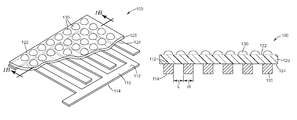
- FIG. 1A illustrates schematically a perspective view of an exemplary embodiment of an electronic indicator
- FIG. 1B illustrates schematically a cross-sectional view of the electronic indicator illustrated in FIG. 1A ;
- FIG. 2 illustrates schematically a partial cross-sectional view of an electronic indicator having an interdigitated electrode sensor
- FIG. 3A illustrates schematically a partial cross-sectional view of an exemplary embodiment of an electronic indicator
- FIG. 3B illustrates schematically a partial cross-sectional view of another exemplary embodiment of an electronic indicator
- FIG. 4A illustrates schematically a top view of an exemplary embodiment of an interdigitated electrode sensor
- FIG. 4B illustrates schematically a top view of another exemplary embodiment of an interdigitated electrode sensor
- FIG. 5 is a picture of an exemplary embodiment of an electronic indicator
- FIG. 6 is a block diagram for an exemplary embodiment of a wash efficacy measurement system
- FIG. 7A illustrates a plot of capacitance versus time resulting from the sequential deposition of eight 10 ⁇ L drops of an artificial soil coating onto the active area of an electronic indicator
- FIG. 7B shows a plot of capacitance versus the volume of artificial soil added to an electronic indicator's surface
- FIG. 7C shows changes in capacitance as soil spots on the electronic indicator are sequentially removed
- FIG. 7D illustrates a plot of total impedance verse the volume of soil added to the sensor's surface
- FIG. 7E shows changes in total impedance as soil spots on an electronic indicator are sequentially removed from the surface of the electronic indicator
- FIG. 7F shows changes in resistance as soil spots on an electronic indicator are sequentially removed from the surface of the electronic indicator
- FIG. 8 shows the capacitance of an electronic indicator as a function of the thickness of an artificial soil coating
- FIG. 9 shows the capacitance response of electronic indicators as a function of volume of water added to the surface of electronic indicators with different thickness of the barrier layer
- FIG. 10 shows the capacitance response of three electronic indicators, each with electrode spacing of 50 ⁇ m, 70 ⁇ m, and 90 ⁇ m respectively;
- FIG. 11 shows a bar chart of (capacitance attributed to soil)/(baseline capacitance) ratio verse electrode spacing
- FIG. 12 shows a flow chart of the method for measuring wash efficacy using an embodiment of an electronic indicator of the present disclosure.
- Decontamination is a process of cleaning objects using physical and/or chemical means. Hospital or other health care facilities often use heat, either steam or hot water, to decontaminate medical devices. Additionally, washing in hot water at proper temperature and for a sufficient amount of time provides a broad disinfecting effect.
- Disinfection is a process capable of destroying and/or removing pathogenic microorganisms. Disinfection processes are intended to destroy or prevent growth of microorganisms capable of causing infections. The microorganisms include, for example, vegetative bacteria, pathogenic fungi, and specifically tested viruses. Disinfection process can be a thermal disinfection process, a chemical disinfection process using chemical disinfectant(s), or a combination thereof. Washing in hot water is a popular way for thermal disinfection due to its low cost and personal and environmental safety.
- Reusable devices or articles often require wash and disinfection after each use. It is important to monitor and ensure the efficacy of such wash and disinfection in cleaning theses devices or articles, especially in cleaning devices or articles to be used in medical, dental, pharmaceutical and veterinary practices.
- Fluid such as hot water or steam
- An effective wash process may require the fluid to be heated to an appropriate temperature range to activate the cleaning agents and enzymes for a sufficiently long time period.
- a thermal disinfection process may require the fluid to be heated to a minimum temperature and for an adequate time period.
- a value a value of equivalent time in seconds at 80° C., is used to evaluate a disinfection efficacy.
- Current indicators in use often require visual inspections that lead to inaccurate results because visual inspection cannot quantify how much soil is left on the indicators. Additionally, visual inspection is a manual process that is subject to operator error (i.e., logging the wrong data, log to the wrong record, etc.).
- an electronic indicator that can be measured by an electrical characteristic reader, where the measured value can be used to evaluate efficacy of a cleaning (i.e., wash, disinfection, etc.) cycle.
- an electrical characteristic reader can be any device, instrument, or circuit that can be used to measure an electrical characteristic, including but not limited to, a capacitance meter, an impedance analyzer, an LCR meter, and a digital multimeter.
- an electronic indicator includes an electronic sensor, artificial soil, and a barrier layer between the electronic sensor and the artificial soil. The barrier layer typically includes dielectric material.
- the electrical characteristic (i.e. capacitance, impedance, inductance, resistance, admittance, current, etc.) of the electronic indicator is typically affected by the attributes of the indicator, for example, the sizes and arrangements of electrode(s) used in the electronic sensor, the volume of the artificial soil, the thickness of the barrier layer, and other attributes of the indicator.
- the volume of artificial soil typically changes during a cleaning cycle (i.e., the volume is reduced) and the electrical characteristic may be varied by the change of the volume of artificial soil.
- the capacitance of the electronic indicator decreases when the volume of artificial soil decreases during a cleaning cycle.
- an electronic indicator is placed into a wash chamber before a cleaning cycle and the electrical characteristic of the electronic indicator can be read by an electrical characteristic reader after the cleaning cycle, which can be used to evaluate the efficacy of the cleaning cycle.
- Artificial soil encompasses a composition comprising a target analyte (i.e., an acid, a base, a nucleotide, a protein, a nucleic acid, a carbohydrate, or hemoglobin), where the presence and/or the residual amount of the target analyte after a cleaning cycle can be used to evaluate the efficacy of the cleaning cycle.
- a target analyte i.e., an acid, a base, a nucleotide, a protein, a nucleic acid, a carbohydrate, or hemoglobin
- the artificial soil can be made from commercially available test soil.
- the artificial soil can be a mixture of 9 mL sterile water added to a single vial of Artificial Test Soil ATS-9 available from Healthmark Industries Company, Inc., Fraser, Mich., USA.
- the artificial soil composition further can comprise an optional dye in an amount sufficient to be optically detectable.
- the artificial soil further comprises a polymeric binder.
- the artificial soil can be prepared by dissolving and/or making a homogeneous dispersion of the target analyte, polymeric binder, and optional dye in a suitable solvent (i.e., water, alcohol, or mixtures thereof), applying the mixture to a surface (i.e., by spraying, dip-coating, or other coating processes known in the art) of a substrate, and removing at least a portion of the solvent (i.e., substantially all of the solvent) to obtain a dried coating on the substrate.
- a suitable solvent i.e., water, alcohol, or mixtures thereof
- Embodiments of the present disclosure are directed to electronic indicators comprising wash-removable artificial soil.
- wash-removable artificial soil refers to artificial soil that can be removed during a cleaning process such that the remaining volume of artificial soil is reduced or eliminated.
- the remaining volume of artificial soil is an indication of the efficacy of the wash process.
- FIG. 1A illustrates schematically a perspective view of an exemplary embodiment of an electronic indicator 100 .
- FIG. 1B illustrates schematically a cross-sectional view of the electronic indicator 100 illustrated in FIG. 1A (cross section at line 1 B).
- the electronic indicator 100 includes an electronic sensor 110 , a barrier layer 120 , and artificial soil 130 .
- the electronic sensor 110 can include one or more electrodes.
- the barrier layer 120 can include one or more dielectric materials. Dielectric material can include, for example, polymeric material, air, glass, ceramic/inorganic material, plastic, and the like.
- Polymeric material can include but is not limited to polyester, polyimide, polyamide-imide, polyvinyl chloride (PVC), poly isobutene (butyl rubber), polytetrafluoroethylene (PTFE), fluorinated ethylene propylene (FEP), polyvinylidene chloride (PVDC), thermoplastic chlorofluoropolymers such as polytrifluorochloroethylene (PTFCE; or Kel-F81), polyethylene terephthalate (PET), polypropylene, polyethylene, polyphenylene sulfide, polyethylene naphthalate, polycarbonate, silicone rubber, ethylene propylene diene rubber (EPDM), polyurethane, acrylate polymers, silicones, natural rubber, epoxies, and synthetic rubber adhesives.
- Ceramic/inorganic material can include but is not limited to metal oxide (i.e., silicon oxide, aluminum oxide, titanium oxide, zirconium oxide, chromium oxide, tantalum oxide, vanadium oxide etc
- the barrier layer may have a thickness in the range of 5 nm to 5 mm.
- the barrier layer 120 may be a continuous slab, layer, or film.
- the barrier layer 120 may include an adhesive layer, for example, an epoxy layer, to attach to the sensor 110 .
- the barrier layer 120 may be an adhesive layer.
- the barrier layer 120 has low moisture permeability.
- the barrier layer can be constructed to provide sufficient physical strength and integrity for the construction of the electronic indicator 100 .
- the artificial soil 130 can include commercially available artificial test soil (ATS) or proprietary artificial soil.
- the barrier layer 120 can have a first barrier surface 122 and a second barrier surface 124 , where the first barrier surface 122 is opposite to the second barrier surface 124 .
- the artificial soil 130 is disposed on at least a portion of the first barrier surface 122 , where the volume of the artificial soil 130 decreases during a washing process.
- the sensor 110 can have a first major sensor surface 112 and an opposing second major sensor surface 114 , wherein the first major sensor surface 112 is adjacent to the second barrier surface 124 .
- the sensor 110 is configured to produce a sensor signal associated with an electrical characteristic of the electronic indicator when the electronic indicator is measured by an electrical characteristic reader.
- the electrical characteristic of the electronic indicator can vary in response to a change in the volume of the artificial soil. For example, when the amount of artificial soil decreases during a cleaning cycle, the total impedance of the electronic indicator can increase.
- the electrical characteristic can be represented by impedance, capacitance, inductance, resistance, other electrical characteristics, and a combination thereof.
- the sensor 110 can include electrodes. In some configurations, the sensor 110 can include electrodes that are generally on the same planar surface. In some other configurations, the sensor 110 can include electrodes that are not on the same planar surface. In some cases, as illustrated in FIG. 1A and FIG. 1B , the electrodes can be metal traces. In FIG. 1B , “L” denotes the distance between two adjacent electrodes, which is also referred to as electrode spacing. “W” denotes the width of an electrode, which is also referred to as electrode line width or electrode “metal trace” width. Electrodes can include any suitable conductive material. In some cases, electrodes can include combinations of different materials (conductive and/or nonconductive), as different layers or as a mixture, as long as sufficient overall conductivity is provided.
- the electrode material may include a constant resistivity of less than about 10 ⁇ 2 ohms-meter.
- materials that can be used in electrodes include, but are not limited to, organic materials, inorganic materials, metals, alloys, and various mixtures and composites comprising any or all of these materials.
- coated (for example, vapor coated, sputter coated, etc.) metals or metal oxides, or combinations thereof, may be used.
- Suitable conductive materials include, for example, aluminum, tin, indium-tin oxide, gold, silver, platinum, palladium, copper, and the like.
- different electrodes may include the same material. In some other cases, different electrodes may include different materials.
- the sensor 110 can include a capacitance sensor, an impedance sensor, other electrical sensors, or a combination thereof.
- the volume of the artificial soil 130 on the active area of the electronic indicator 100 can change the overall capacitance of the electronic indicator 100 .
- an active area of an electronic indicator refers to the area that the sensing component covers. For example, it can be the area where the sensitivity of the electrical field of electrodes is greater than a certain threshold.
- One of the factors that will determine the amount of change in the electrical characteristic is the dielectric properties of the artificial soil 130 .
- the electronic indicator can be used to determine how much artificial soil 130 remains on the surface after a cleaning cycle and/or how much artificial soil 130 is washed away.
- the artificial soil 130 can be arranged as a layer to cover at least a portion of the first barrier surface 122 .
- the artificial soil 130 can be also arranged into soil areas as illustrated in FIG. 1A . The areas can be in the shapes of circles, oval, or other shapes.
- the artificial soil 130 can be arranged to a layer (i.e., soil layer) covering at least a portion of the first barrier surface 122 and additionally arranged into areas that are disposed on the soil layer.
- FIG. 2 illustrates schematically a partial cross-sectional view of an electronic indicator having an interdigitated electrode sensor 200 .
- the electronic indicator 200 includes a sensor 210 , a barrier layer 220 , and artificial soil 230 .
- the sensor 210 can include interdigitated electrodes.
- the sensor 210 can include two electrodes 210 A and 210 B arranged interdigitated manner.
- each of the two electrodes 210 A and 210 B can be applied with direct current (DC) or alternating current (AC) potentials by the reader.
- DC direct current
- AC alternating current
- electrode 210 A can be applied with a DC positive potential
- electrode 210 B can be applied with a DC negative potential.
- electrode 210 A can be applied with an AC positive electric potential and electrode 210 B can be applied with an AC negative electric potential at one point in time.
- the sensor 210 can include an interdigitated electrode sensor having two electrodes. In some other implementations, the sensor 210 can include an interdigitated electrode sensor having three or more electrodes.
- the electronic indicator 200 can generate a sinusoidal electric field extending normal to the major surface of the sensor, illustrated as 250 . In some cases, the field strength decreases rapidly from the major sensor surface.
- interdigitated encompasses any arrangement comprising at least two electrodes present in an interdigitated configuration.
- Such configurations include interdigitated comb patterns (as depicted in FIG. 2 ), as well as interdigitated spiral patterns, interdigitated serpentine patterns, or the like.
- at least two electrodes are present in a largely coplanar interdigitated arrangement with a dielectric layer present in proximity to the electrodes such that an electric field is established between the electrodes.
- the dielectric layer/material may be provided between the electrodes (i.e. in the plane of the two electrodes and interposed in the closest linear path between any two points of approach of the first and second electrodes).
- the dielectric layer/material may be provided such that, while not coplanar with the electrodes, the dielectric material is exposed at least to the fringing electric field that is established between adjacent sections of the two electrodes.
- the dielectric layer may be provided in both locations.
- at least two electrodes are present in an interdigitated arrangement while the electrodes are on different planar surfaces with a dielectric layer present in proximity to the electrodes.
- Interdigitated electrodes can be provided by the deposition of conductive material in two interdigitated patterns by any of the methods (e.g. masked vapor deposition, screen-printing, ink-jet printing) that are well known for patterned deposition of materials.
- the particular geometric/dimensional properties of the electrode patterns may be designed as desired.
- FIG. 3A illustrates schematically a partial cross-sectional view of an exemplary embodiment of an electronic indicator 300 .
- the electronic indicator 300 includes a sensor 310 , a barrier layer 320 , artificial soil 330 , an optional insulating layer 340 , and an optional shielding layer 350 .
- the sensor 310 can include one or more electrodes that can produce sensor signals indicating an electrical characteristic (i.e., impedance, capacitance, etc.) of the electronic indicator 300 when it is measured by an electrical characteristic reader (i.e., impedance analyzer, capacitance reader, etc.).
- the barrier layer 320 can include any dielectric material that is feasible to provide insulation between the sensor 310 and the artificial soil 330 .
- the barrier layer 320 can be a relative thin layer so the indicator 300 is sensitive to the volume change of the artificial soil.
- the optional insulating layer 340 can include any dielectric material that is suitable for physical and electrical requirement.
- the material used in the insulating layer 340 can include the same materials as listed above for the barrier layer.
- the insulating layer 340 can include a silicone based pressure sensitive adhesive coated on a polyester substrate.
- the insulating layer 340 can be a relative thick layer to provide physical support for the electronic indicator 300 .
- the insulating layer can have low moisture permeability.
- the insulating layer 340 can be chosen to be thick enough to ensure that the sensing field created by the electrodes (i.e., depicted as 250 in FIG. 2 ) is fully contained within the insulating layer 340 .
- Such configurations may help increase electronic indicator's sensitivity to the changes in the volume of artificial soil 330 .
- the sensitivity of an electronic indicator can be indicated by the magnitude of changes in the electrical characteristic of the electronic indicator 300 caused by changes in the volume of artificial soil 330 .
- the barrier layer 320 and the insulating layer 340 may have the same materials. In some other embodiments, the barrier layer 320 and the insulating layer 340 may not have the same materials.
- the barrier layer 320 can have a first barrier surface 322 and a second barrier surface 324 , where the first barrier surface 322 is opposite to the second barrier surface 324 .
- the artificial soil 330 is disposed on at least a portion of the first barrier surface 322 , where the volume of the artificial soil 330 typically decreases during a cleaning process (i.e., a wash process, a disinfection process, or a combination thereof).
- the sensor 310 can have a first major sensor surface 312 and an opposing second major sensor surface 314 , wherein the first major sensor surface 312 is adjacent to the second barrier surface 324 .
- the insulating layer 340 can have a first insulating layer surface 342 and an opposing second insulating layer surface 344 , wherein the first insulating layer surface 342 is adjacent to the second major sensor surface 314 and covers at least a portion of the second major sensor surface 314 .
- the electronic indicator 300 can include a shielding layer 350 .
- the shielding layer 350 may include any conductive material, for example, conductive organic materials, inorganic materials, metals, alloys, and various mixtures. Suitable conductive materials include for example aluminum, tin, indium-tin oxide, gold, silver, platinum, palladium, copper, and the like.
- the shielding layer 350 can reduce electrical interference when the electrical indicator 300 is being measured.
- the shielding layer may include a conductive material disposed on at least a portion of the second insulating layer surface 344 . In some cases, the shielding layer 350 can function as a grounding electrode for the sensor 310 .
- FIG. 3B illustrates schematically a partial cross-sectional view of another exemplary embodiment of an electronic indicator 300 B.
- the electronic indicator 300 B can include a sensor 310 , a first barrier layer 320 A, first artificial soil 330 A that is disposed on the first barrier layer 320 A, a second barrier layer 320 B, and second artificial soil 330 B that is disposed on the second barrier layer 320 B.
- an electrical characteristic i.e., impedance, capacitance, resistance, inductance, etc.
- an electrical characteristic of the indicator 300 B can be varied by both the volume of the first artificial soil 330 A and the volume of the second artificial soil 330 B.
- FIG. 4A illustrates schematically a top view of an exemplary embodiment of an interdigitated electrode sensor 400 .
- the interdigitated electrode sensor 400 can include electrodes 410 and 420 that are arranged as illustrated in FIG. 4A .
- Contact pads 415 are optional components and include conductive materials (i.e., copper, etc.), which can be used to allow better and easy connection during measurement.
- FIG. 4B illustrates schematically a top view of another exemplary embodiment of an interdigitated electrode sensor 400 .
- the interdigitated electrode sensor 400 can include sensing electrodes 410 and 420 , optional guard electrode 430 , and optional ground electrode 440 .
- Contact pads 415 are optional components that can be used to allow better and easy connection during measurement.
- the guard electrode 430 can provide shielding of sensing electrodes (i.e., electrodes 410 and 420 ) in the plane of the sensor.
- the ground electrode 440 can provide shielding of the guard electrodes (i.e. guard electrode 430 ) and/or other electrodes.
- the length of the sensor 400 can be in the range of 0.5 cm to 25 cm and the width of the sensor 400 can be in the range of 0.5 cm to 25 cm.
- a typical length of the sensor 400 can be in the range of 1 cm to 10 cm and a typical width of the sensor 400 can be in the range of 0.5 cm to 5 cm.
- the electrode spacing between adjacent metal traces for interdigitated electrodes can be 5 ⁇ m to 1 cm.
- Typical electrode spacing between adjacent metal traces is 10 ⁇ m to 500 ⁇ m.
- a more typical spacing between adjacent metal traces is 50 ⁇ m to 200 ⁇ m.
- the electrode line width of metal traces for interdigitated electrodes can be 5 ⁇ m to 1 cm.
- a typical line width of metal traces is 10 ⁇ m to 500 ⁇ m.
- a more typical width of metal traces is 50 ⁇ m to 200 ⁇ m. In such configurations, tens or hundreds of metal traces are included in the sensor 400 .
- FIG. 5 is a picture of an exemplary embodiment of an electronic indicator 500 .
- the electronic indicator 500 includes two copper strips 510 that can be used to connect the electronic indicator 500 to a measuring device.
- the electronic indicator 500 also includes a polyimide barrier layer 530 and eight individual spot coatings 520 of artificial soil disposed on top of the barrier layer 530 .
- the electrode spacing and electrode line width of the electrodes is 75 ⁇ m and the area with metal traces is 2.44 cm ⁇ 1.02 cm (i.e., active area of the electronic indicator).
- the barrier layer uses a 25 ⁇ m thick polyimide films.
- the indicator 500 can be connected to impedance analyzer through copper tapes and additional wires. Transparent tapes can be applied to cover and insulate copper electrodes.
- the indicator 500 can be placed on a hot plate with the polyimide side up.
- the hot plate can be maintained at a high temperature (i.e., 60° C.) in order to expedite the drying process of artificial soils.
- An amount of 10 ⁇ L of artificial soil per spot can be delivered using a micropipette.
- the size of artificial soil spot can be generally uniform.
- FIG. 6 is a block diagram for an exemplary embodiment of a wash efficacy measurement system 600 .
- the wash efficacy measurement system 600 includes an electronic indicator 610 and an electrical characteristic reader 620 .
- the electronic indicator 610 is configured to be disposed in a wash chamber during a cleaning cycle (i.e., wash or disinfection, etc.).
- the electronic indicator 610 can be placed in the wash chamber of a GETINGE 46-series washer disinfector available from Getinge USA, Inc., Rochester, N.Y., which can be used to clean (i.e., wash and disinfect) surgical instruments before they are sterilized.
- the electronic indicator 610 can be implemented by any of the above mentioned embodiments.
- the electronic indicator 610 includes a barrier layer 630 having a first barrier surface and an opposing second barrier surface; a volume of wash-removable artificial soil 640 disposed on at least a portion of the first barrier surface; and a sensor 650 having a first major sensor surface and an opposing second major sensor surface.
- the barrier layer 630 includes a dielectric material. The volume of the artificial soil typically decreases during a cleaning cycle. The first major sensor surface is adjacent to the second barrier surface.
- the sensor 650 is configured to produce a sensor signal associated with an electrical characteristic of the electronic indicator 610 when the electronic indicator 610 is measured by an electrical characteristic reader. The electrical characteristic of the electronic indicator 610 varies in response to a change in the volume of the artificial soil 640 .
- the electrical characteristic reader 620 is configured to measure an after-wash electrical characteristic of the electronic indicator after the cleaning cycle, where the after-wash electrical characteristic of the electronic indicator can indicate an efficacy of the cleaning cycle.
- the sensor 650 can include an interdigitated electrode sensor.
- the interdigitated electrode sensor can include two electrodes, where the electrical characteristic reader 620 can provide potentials to the two electrodes.
- the electrical characteristic reader 620 can be further configured to measure a before-wash electrical characteristic of the electronic indicator 610 before the cleaning cycle, wherein the efficacy of the cleaning cycle is determined based on the before-wash electrical characteristic of the electronic indicator 610 and the after-wash electrical characteristic of the electronic indicator 610 .
- the before-wash electrical characteristic of the electronic indicator 610 is measured when the electronic indicator 610 does not have artificial soil.
- E BeforeNoSoil can be a predetermined value for electronic indicators with identical configurations.
- the before-wash electrical characteristic of the electronic indicator 610 is measured when the electronic indicator 610 has artificial soil applied to its surface.
- a capacitance measurement can be suitable to detect changes in the volume of artificial soil.
- the electrical characteristic sensitive to the change of the soil volume can include resistance.
- E BeforeWithSoil can be a predetermined value for electronic indicators with identical configurations.
- the electronic indicator used to monitor the efficacy of a cleaning cycle can include a capacitor sensor.
- an after-wash capacitance (C After ) of the electronic indicator can be measured by a capacitor meter after the cleaning cycle to determine the efficacy of the cleaning cycle.
- a before-wash capacitance (C BeforeWithSoil or C BeforeNoSoil ) of the electronic indicator with or without soil can be measured by a capacitor meter before the cleaning cycle, where the efficacy of the cleaning cycle can be evaluated based on both the after-wash capacitance and the before-wash capacitance.
- the efficacy of the cleaning cycle can be indicated by the differentials between the after-wash capacitance and the before-wash capacitance.
- a wash efficacy monitor system can use an electronic indicator to monitor the efficacy of a cleaning cycle in real-time.
- the electronic indicator can connect to an electronic characteristic reader during a cleaning cycle, for example, via an insulated wire.
- the electrical characteristic of the electronic indicator can be measured continuously, at certain cycle time, and/or with a certain sample rate by the electronic characteristic reader.
- the wash efficacy monitor system can analyze the measured data and generate a signal indicative of the wash efficacy, for example, by a processor-based device.
- the processor-based device can be the electrical characteristic reader and/or a separate device. Such signal can be used to adjust the cleaning cycle, for example, to expand or shorten the cycle time or to change the configuration of the cleaning cycle.
- At least some aspects of the present disclosure are directed to methods for measuring wash efficacy.
- dispose an electronic indicator in a wash chamber during a cleaning cycle (step 1210 ).
- the electronic indicator typically includes a sensor and a volume of wash-removable artificial soil disposed on at least a portion of a surface of the electronic indicator.
- the sensor is configured to produce a sensor signal associated with an electrical characteristic of the electronic indicator, where the electrical characteristic of the electronic indicator varies in response to a change in the volume of the artificial soil.
- measure an after-wash electrical characteristic of the electronic indicator after the cleaning cycle step 1220 ).
- a wash efficacy monitoring system records the after-wash electrical characteristic of the electronic indicator (step 1230 ) in, for example, a device memory, a file, a database, or the like.
- the system determines an efficacy of the cleaning cycle based on the after-wash electrical characteristic of the electronic indicator.
- a plurality of after-wash electrical characteristic of electronic indicators are collected for a specific cleaning equipment, a specific position within a cleaning equipment, equipment of a specific organization, or other levels.
- a threshold electrical characteristic can be determined based on the plurality of after-wash electrical characteristic of electronic indicators, where the threshold electrical characteristic can be used to determine efficacy of a cleaning cycle. For example, a measured after-wash electrical characteristic is compared with the threshold electrical characteristic to determine efficacy of the cleaning cycle.
- an action limit can be defined based on a plurality of after-wash electrical characteristic of electronic indicators collected under a controlled condition, where the action limit is associated with a predetermined action.
- Action limit refers to a threshold electrical characteristic measured after a cleaning cycle under a controlled condition (i.e., a selected volume of artificial soil with a pre-defined equipment condition and/or decontamination process), which indicates a particular sub-process or a series of sub-processes failed to remove or inactivate an acceptable amount of soil from the article.
- Action limits can be used to determine what actions (e.g., re-processing the load, equipment maintenance), if any, should be taken as a result of inadequate removal of artificial soil from electronic indicators.
- Action limits for controlling a multi-step cleaning, washing, and decontamination process are disclosed in International Patent Publication No. WO 2012/112482, which is incorporated herein by reference in its entirety.
- a system can compare the after-wash electrical characteristic of the electronic indicator to an action limit and provide a signal indicative of a predefined action based on the comparison. For example, if an after-wash electrical characteristic of the electronic indicator is above or below an action limit requiring equipment maintenance (e.g., adding detergent), the system can provide a warning message of “equipment maintenance” to users.
- the system can collect electrical characteristic in real time during a cleaning cycle, compare the value or a set of values with the action value, and provide a signal indicative of a predefined action based on the comparison. For example, the system can inform the user of “equipment maintenance” before the completion of a cleaning cycle.
- the sensitivity of the sensor used in an electronic indicator can affect the sensitivity of the sensor used in an electronic indicator, where the sensitivity is often associated with the change in the electrical characteristic verse the change in the amount of artificial soil. For example, for a fixed change in the amount of artificial soil (i.e., 20 ⁇ L reduction, etc.), an electronic indicator having the larger change in the electrical characteristic (i.e., 20 pF reduction in capacitance v. 10 pF reduction in capacitance) will have a higher sensitivity.
- the first factor is the characteristics of the area covered by the artificial soil. For example, the shape, size, position, and other attributes of the sensor's coating area may affect the sensitivity of the sensor.
- the second factor is the artificial soil coating thickness.
- the senor can be most sensitive to the portion of the soil coating closest to the barrier layer's surface. In some cases, a very thick soil coating will eventually saturate the sensor's response. Because the sensor can be sensitive to any residual soil coating remaining on the barrier layer's surface, the soil coating thickness can be chosen to maximize the response given by the sensor, but also to appropriately challenge the operation of a cleaning cycle.
- the third factor is the barrier layer thickness. In general, the thinner the barrier layer is the higher the sensitivity of the sensor. In some implementations, this particular factor can be used to fine tune the performance of the electronic indicator.
- the fourth factor is the spacing between adjacent electrodes, which is also referred to as electrode spacing (i.e., the length of L in FIG. 1B ). In some cases, sensors with larger spacing have smaller capacitance but more extensive sensing fields and can probe thicker soil coating.
- a capacitance of an electronic indicator can be measured to monitor efficacy of a cleaning cycle.
- FIG. 7A illustrates a plot of capacitance versus time resulting from the sequential deposition of eight 10 ⁇ L drops of an artificial soil onto the active area of an electronic indicator (as shown in FIG. 5 ).
- the plot illustrates the step changes (S 1 , S 2 , . . . S 8 ) measured in capacitance as a drop of artificial soil is added to the electronic indicator's surface.
- the first drop of artificial soil is added at approximately 50 seconds, the second drop at approximately 400 seconds, and the remaining six drops at approximately 30 second intervals thereafter.
- capacitances can measured by an impedance analyzer (i.e., a Solartron Impedance/Gain-Phase Analyzer Model 1260, from Solartron Analytical, Hampshire, UK) applying 100 mV at 10 kHz across the interdigitated electrodes.
- the capacitance values can be calculated from imaginary impedances based on a serial resistor-capacitor circuit configuration.
- FIG. 7B shows a plot of capacitance versus the volume of soil added to an electronic indicator's surface, where the data is derived from the data in FIG. 7A .
- the capacitance of the electronic indicator increases when the volume of artificial soil increases. In some cases, the increase in the capacitance is close to linearly proportional to the increase in the volume of the artificial soil.
- FIG. 7D illustrates a plot of total impedance verse the volume of soil added to the sensor's surface. In some embodiments, the total impedance of the electronic indicator decreases when the volume of artificial soil increases. In some cases, as illustrated in FIG. 7D , the decrease in the total impedance is close to linearly proportional to increase in the volume of the artificial soil.
- FIG. 7C shows changes in capacitance as soil spots on an electronic indicator (as illustrated in FIG. 5 ) are sequentially removed from the surface of the electronic indicator.
- cotton balls may be used to remove one soil spot at a time where the other spots were intact.
- a decrease in capacitance due to the soil spots being removed can be observed.
- the decrease in capacitance has generally linear or close to linear relationship with the amount of artificial soil being removed from the indicator surface. Because of this relationship, the electronic indicator can be used to determine the amount of residual artificial soil, if any, left on its surface after a cleaning cycle that can be used to determine efficacy of the cleaning cycle.
- the initial value of the capacitance with eight soil spots is approximately 50 pF in FIG. 7C
- the ending value of the capacitance with eight soil spots is approximately 59 pF in FIG. 7B . This difference is because the soil spots are not completely dried when the capacitance is measured to generate the plot in FIG. 7B , where the soil spots are dried when the capacitance is measured to generate the plot in FIG. 7C .
- FIG. 7E shows changes in total impedance as soil spots on an electronic indicator (as illustrated in FIG. 5 ) are sequentially removed from the surface of the electronic indicator.
- an increase in total impedance due to the soil spots being removed can be observed.
- the increase in total impedance has generally linear or close to linear relationship with the amount of artificial soil being removed from the indicator surface. Because of this relationship, impedance of the electronic indicator can be measured to determine the amount of residual artificial soil, if any, left on its surface after a cleaning cycle that can be used to determine the efficacy of the cleaning cycle.
- FIG. 7F shows changes in resistance as soil spots on an electronic indicator (as illustrated in FIG. 5 ) are sequentially removed from the surface of the electronic indicator.
- a decrease in resistance due to the soil spots being removed can be observed.
- the decrease in resistance has generally linear or close to linear relationship with the amount of artificial soil being removed from the indicator surface. Because of this relationship, resistance of the electronic indicator can be measured to determine the amount of residual artificial soil, if any, left on its surface after a cleaning cycle that can be used to determine the efficacy of the cleaning cycle.
- FIG. 8 shows the capacitance of an electronic indicator as a function of the thickness of an artificial soil coating.
- the capacitance of the electronic indicator will increase with increased artificial soil coating thickness.
- the electronic indicator's capacitance response is saturated. After the saturation point, further increases in the thickness of the soil coating have no effect.
- the capacitance response is saturated because the soil coating thickness extends beyond the physical volume that the evanescent electric field is probing.
- electrical indicators can be constructed to have a selected thickness of artificial soil coating, so the indicators have appropriate sensitivity for wash monitoring and the capacitance response is not saturated.
- a capacitance measuring device that is capable of measuring with a resolution of 1 pF will be able to detect a thin residual soil coating, for example, a soil coating with thickness approximately 10 ⁇ m in the soil coated area of 1 cm 2 .
- FIG. 9 shows the capacitance response of electronic indicators as a function of volume of water added to the surface of electronic indicators with different thickness of the barrier layer.
- the data shown compares two electronic indicators identical in design features with the exception of the barrier layer thickness (25 ⁇ m versus 50 ⁇ m). Water is added onto the active area of both indicators, with one drop at a time. In this experiment, each drop of water is 10 ⁇ L.
- an electronic indicator with 25 ⁇ m thick barrier layer is more sensitive to the change of water adding on the surface of the indicator than an electronic indicator with 50 ⁇ m thick barrier layer. This can be because the majority of the probing electric field for an electronic indicator with a thicker barrier layer (i.e., 50 ⁇ m) resides within the barrier layer itself.
- an electronic indicator with a thinner barrier layer may be a preferred configuration.
- FIG. 10 shows the capacitance response of three electronic indicators, each with electrode spacing of 50 ⁇ m, 70 ⁇ m and 90 ⁇ m respectively.
- the baseline capacitance of the electrical indicator i.e., the capacitance measured when the indicator does not have artificial soil coated
- the electrode spacing i.e., when the electrode spacing increases, the baseline capacitance decreases.
- FIG. 11 shows a bar chart of (capacitance attributed to soil)/(baseline capacitance) ratio, also referred to as soil/baseline ratio, verse electrode spacing.
- the soil/baseline ratio for a 90 ⁇ m electrode spacing electronic indicator is greater than 90%, while the soil/baseline ratio for a 50 ⁇ m electrode spacing electronic indicator is only about 30%.
- An electronic indicator as illustrated in FIG. 5 was prepared an active area of metal (copper) traces of 2.44 cm ⁇ 1.02 cm (i.e., active area of the electronic indicator); the spacing between individual metal traces (electrodes) was 75 ⁇ m and the width of individual metal traces was 75 ⁇ m.
- the barrier layer was a 25 ⁇ m thick KAPTON E brand polyimide film, available from Du Pont of Circleville, Ohio.
- the indicator was connected to impedance analyzer through copper tapes and additional wires. Transparent tape insulating layer was applied to cover and insulate copper electrodes.
- the insulating layer was SCOTCH brand Premium Heavy Duty Packaging Tape 3750, available from 3M Company of St. Paul, Minn.
- the indicator electrode was placed on a hot plate with the polyimide side up.
- the hot plate was maintained at a high temperature (60° C.) in order to expedite the drying process of deposited artificial soil.
- An artificial soil was prepared as a mixture of 9 mL sterile water added to a single vial of Artificial Test Soil ATS-9 available from Healthmark Industries Company, Inc., Fraser, Mich., USA. 10 ⁇ L of the artificial soil per spot was delivered to the electrode surface using a micropipette. The size of artificial soil spot was generally uniform.
- FIG. 7A A plot of capacitance versus time resulting from the sequential deposition of eight 10 ⁇ L drops of an artificial soil onto the active area of the electronic indicator of Example 1 is illustrated in FIG. 7A .
- the plot of FIG. 7A The plot of FIG.
- FIG. 7A illustrates the step changes (S 1 , S 2 , . . . S 8 ) measured in capacitance as a drop of artificial soil was added to the electronic indicator's surface.
- the first drop of artificial soil is added at approximately 50 seconds, the second drop at approximately 400 seconds, and the remaining six drops were added at approximately 30 second intervals thereafter.
- the capacitances were measured by an impedance analyzer (i.e., a Solartron Impedance/Gain-Phase Analyzer Model 1260, from Solartron Analytical, Hampshire, UK) applying 100 mV at 10 kHz across the interdigitated electrodes.
- the capacitance values were calculated from imaginary impedances based on a serial resistor-capacitor circuit configuration.
- FIG. 7B shows a plot of capacitance versus the volume of soil added to the electronic indicator's surface, of Example 1, where the data is derived from the data in FIG. 7A .
- the capacitance of the electronic indicator increases when the volume of artificial soil increases. The increase in the capacitance is close to linearly proportional to the increase in the volume of the artificial soil.
- FIG. 7D illustrates a plot of total impedance verse the volume of soil added to the electronic indicator's surface. The total impedance of the electronic indicator decreased in a linearly proportional fashion when the amount of artificial soil increased.
- FIG. 7C shows changes in capacitance as the number of soil spots on the electronic indicator Example 1 were sequentially removed from the surface of the electronic indicator using cotton balls to remove one soil spot at a time where the other spots were left intact.
- This simulated (in a controlled fashion) the removal of artificial soil during a cleaning cycle to which the electronic indicator would be subjected.
- the decrease in capacitance had a generally linear or close to linear relationship with the amount of artificial soil being removed from the indicator surface.
- the electronic indicator can be used to determine the amount of residual artificial soil, if any, left on its surface after a cleaning cycle that can be used to determine efficacy of the cleaning cycle. Note that the initial value of the capacitance with eight soil spots was approximately 50 pF in FIG.
- FIG. 7E shows changes in total impedance as soil spots on the electronic indicator of Example 1 were sequentially removed from the surface of the electronic indicator. As illustrated in FIG. 7E , the increase in total impedance was generally linear or close to a linear relationship with the amount of artificial soil that was removed from the indicator surface. Thus, impedance of the electronic indicator can be measured to determine the amount of residual artificial soil, if any, left on its surface after a cleaning cycle that can be used to determine the efficacy of the cleaning cycle.
- FIG. 7F shows changes in resistance as soil spots on the electronic indicator of Example 1 were sequentially removed from the surface of the electronic indicator. As illustrated in FIG. 7F , the decrease in resistance was generally linear or close to a linear relationship with the amount of artificial soil being removed from the indicator surface. Thus, resistance of the electronic indicator can be measured to determine the amount of residual artificial soil, if any, left on its surface after a cleaning cycle that can be used to determine the efficacy of the cleaning cycle.
- Example 2 Additional electronic indicators were prepared and measured in the same fashion as Example 1, but with different thicknesses of artificial soils coated onto the electrode.
- Table 1 and FIG. 8 show the capacitance of the electronic indicators of Example 2 as a function of the thickness of an artificial soil coating.
- the capacitance of the electronic indicator increased with increased artificial soil coating thickness.
- the electronic indicator's capacitance response was saturated. After the saturation point, further increases in the thickness of the soil coating had no effect. It is suggested that the capacitance response was saturated because the soil coating thickness extends beyond the physical volume that the evanescent electric field was probing.
- Example 2 the capacitance response was saturated at a soil coating thickness of approximately 100 ⁇ m, with a peak response of about 10 pF/cm 2 . Therefore, a capacitance measuring device that is capable of measuring with a resolution of 1 pF can detect a thin residual soil coating, even as thin as approximately 10 ⁇ m in the soil coated area of 1 cm 2 .
- electrical indicators should be constructed to have a selected thickness of artificial soil coating, so that the indicators have appropriate sensitivity for wash monitoring and the capacitance response is not saturated.
- This can be a particularly attractive feature of electronic indicators for wash and/or cleaning monitoring. This is because it allows the artificial soil coating thickness to be chosen primarily on the basis of what will provide an appropriate challenge to a given cleaning cycle without compromising the sensitivity of the electronic indicator (i.e., the thickness of the artificial soil coating is not too thick). This also allows the electronic indicator to be sensitive to any residual soil coating left on the electronic indicator's surface as a result of an inadequate cleaning cycle.
- FIG. 9 shows the capacitance response of the electronic indicators of Example 3 as a function of the volume of water added to the surface of electronic indicators with different thicknesses of the barrier layer. As the surface area of the electronic indicator covered by water increased, the capacitance also increased.
- the rate of increase in capacitance with the addition of water was higher for the electrode with the 25 ⁇ m thick barrier layer than it was for the electronic indicator with 50 ⁇ m think barrier layer. This indicates that the electronic indicator with 25 ⁇ m thick barrier layer is more sensitive to addition of water on the surface of the indicator than an electronic indicator with 50 ⁇ m thick barrier layer. This may be because the majority of the probing electric field for an electronic indicator with a thicker barrier layer (i.e., 50 ⁇ m) resides within the barrier layer itself.
- Example 4 electronic indicators were prepared and measured in the same fashion as Example 1, but with the following exceptions.
- the barrier layer was a 25 ⁇ m thick polyimide film, available from Multek Flexible Circuits, Inc. of Northfield, Minn. 200 ⁇ L of artificial soil was applied to 2.5 cm 2 of electrode area and then the indicators were dried at 60° C. for 20 minutes. The estimated thickness is 51.3 ⁇ m. Also three different metal trace thicknesses and spacing were used. The spacing between individual metal traces was 50 ⁇ m and the width of individual metal traces was 50 ⁇ m for Example 4A. spacing between individual metal traces was 70 ⁇ m and the width of individual metal traces was 70 ⁇ m for Example 4B.
- FIG. 10 shows the capacitance response of three electronic indicators of Example 4, each with electrode spacing of 50 ⁇ m, 70 ⁇ m and 90 ⁇ m respectively.
- the baseline capacitance of the electrical indicator i.e., the capacitance measured when the indicator does not have artificial soil coated
- was affected by the electrode spacing i.e., when the electrode spacing increases, the baseline capacitance decreases).
- Example 5 electronic indicators were prepared and measured in the same fashion as Example 4, but with the exception that the SCOTCH Packaging Tape 3750 insulating layer was replaced with a tape made of silicone polyurea (SPU) adhesive on a polyester backing. The effects of electrode spacing on electronic indicator designs were further investigated. Table 2 shows the cycle parameters for an “adequate” wash cycle (i.e., the amount of residue soil is close to 0) in a GETINGE 46-4 model washer disinfector available from Getinge USA, Inc., Rochester, N.Y.
- Table 3 shows the capacitance of four replicate samples (S1-S4) of electronic indicators of Example 5A, 5B and 5C, with 50 ⁇ m, 70 ⁇ m and 90 ⁇ m electrode spacing, respectively, after an adequate wash cycle in the GETINGE washer-disinfector, as well as the baseline capacitance of the same electronic indicators (clean uncoated indicators).
- Table 4 shows the cycle parameters for an “inadequate” wash cycle (i.e., the amount of residue soil is inadequately large) in the GETINGE 46-4 model washer disinfector.
- Table 5 shows the capacitance of four different replicate samples (S5-S8) of electronic indicators of Example 5A, 5B and 5C, with 50 ⁇ m, 70 ⁇ m and 90 ⁇ m electrode spacing, respectively, after an inadequate wash cycle in the same washer-disinfector. Comparing the data in Table 3 and Table 5, the ⁇ Capacitance in an adequate wash cycle was generally smaller in value than ⁇ Capacitance in an inadequate wash cycle. Paired t-tests comparing adequate and inadequate wash cycles were conducted by each electrode spacing, 50 ⁇ m, 70 ⁇ m, and 90 ⁇ m respectively. Table 6 lists the resulting p-values. The p-values indicated the statistical confidence value of a difference between an adequate wash cycle and an inadequate wash cycle.
- Example 6A electronic indicators were prepared and measured in the same fashion as Example 5C, with 90 ⁇ m electrode spacing and 90 ⁇ m widths of individual metal traces.
- the baseline capacitance of each uncoated electronic indicator in Example 6A was first measured prior to coating.
- An artificial test soil was prepared as follows.
- CEVOL brand polyvinyl alcohol polymer was obtained from Sekisui Specialty Chemicals (Secaucus, N.J.).
- a solution of FD&C Red Dye #40 was prepared by dissolving 160 mg of F&DC Red Dye #40 into 40 mL of sterile water. The 4 mg/mL Red Dye #40 solution was placed in a water bath at 80° C.
- CELVOL 425 polyvinyl alcohol polymer was added to each jar at a rate of about 1.0 gram/minute with stirring to obtain a final concentration of approximately 10 weight percent of the binder. The mixture was stirred for about one hour to allow the polymeric binder to fully dissolve. The final concentration of Red Dye #40 was 0.13 mg/mL, which was added primarily for visibility when coating the electronic indicators.
- Each electronic indicator of Example 6A was coated with 100 ⁇ L of the artificial test soil over the active area of each electronic indicator. The coated capacitance of each electronic indicator in Example 6A was measured after coating with the artificial test soil. The samples of Example 6A were divided into multiple sub-groups that were used to assess the wash disinfecting cycles of hospital grade commercial machines.
- the P1 cycle represented a “normal” load of surgical instruments and a regular wash cycle.
- the P2 cycle represented a heavy duty wash cycle and contained surgical instruments that were typically more soiled than those in the “normal” load.
- Example 6B electronic indicators were prepared and measured in the same fashion as Example 6A, with 90 ⁇ m electrode spacing and 90 ⁇ m widths of individual metal traces.
- Example 6B samples were subjected to the adequate and inadequate wash cycles described in Tables 2 and 4 respectively using the GETINGE 46-4 model washer disinfector of Example 5.
- Table 8 shows the % soil remaining results of the samples of Example 6B, calculated according the equation described in Example 6A.
- the electronic indicator of Example 7 was prepared and measured in the same fashion as Example 6A, with 90 ⁇ m electrode spacing and 90 ⁇ m widths of individual metal traces. An amount of 100 ⁇ L of the artificial test soil, described in Example 6A, was coated over the active area of the electronic indicator. In addition, this electronic indicator had a set of lead wires permanently attached to the electrode contact pads that were hermetically sealed using an epoxy coating. The lead wires were approximately 91 cm long. This construction allowed for continuous simulated “remote” (91 cm distance away) measurement of the electronic indicator's capacitance while the electronic indicator was fully immersed in a solution. The wash disinfection cycle of an automated washer disinfector was simulated by using a glass beaker on a heated plate containing a series of rinse and wash solutions through the following sequence of steps:
- Step 4 was carried out in an oven held at a constant temperature of 60° C.
- 3M BMEC Enzymatic Detergent available from 3M Company of St. Paul, Minn. was used at a concentration specified in the manufacturer's instructions.
- the water used for all solution was reverse osmosis (RO) purified water.
- Table 9 reports the capacitance measured in situ at the end of each step in the simulated wash and disinfection cycle. In addition, Table 9 also reports the baseline capacitance of the electronic indicator as well as the coated capacitance of the electronic indicator prior to the simulated wash and disinfection cycle, and the final capacitance of the electronic indicator 24 hours after completion of Step 4 in the simulated cycle. Five replicate measurements were made at each step and averaged together. All error bars are one standard deviation.
- Embodiment One is an electronic indicator to monitor efficacy of a cleaning cycle, comprising:
- barrier layer comprising a first dielectric material, the barrier layer having a first barrier surface and a second barrier surface, the first barrier surface being opposite to the second barrier surface;
- a sensor having a first major sensor surface and an opposing second major sensor surface
- first major sensor surface is adjacent to the second barrier surface
- an electrical characteristic of the electronic indicator varies in response to a change in the volume of the artificial soil.
- Embodiment Two is the electronic indicator of Embodiment One, wherein the sensor is configured to produce a sensor signal associated with the electrical characteristic of the electronic indicator when the electronic indicator is measured by an electrical characteristic reader.
- Embodiment Three is the electronic indicator of Embodiment One or Two, wherein the sensor comprises an interdigitated electrode sensor.
- Embodiment Four is the electronic indicator of Embodiment Three, wherein the interdigitated electrode sensor comprises three or more electrodes.
- Embodiment Five is the electronic indicator of any one of the preceding Embodiments, further comprising an insulating layer comprising a second dielectric material and having a first insulating layer surface and an opposing second insulating layer surface, wherein the first insulating layer surface is adjacent to the second major sensor surface and covers at least a portion of the second major sensor surface.
- Embodiment Six is the electronic indicator of Embodiment Five, further comprising a shielding layer comprising a conductive material disposed on at least a portion of the second insulating layer surface.
- Embodiment Seven is the electronic indicator of any one of the preceding Embodiments, wherein the barrier layer has a thickness in the range of 5 nm to 5 mm.
- Embodiment Eight is the electronic indicator of any one of the preceding Embodiments, wherein the electrical characteristic of the electronic indicator comprises at least one of capacitance characteristic, impedance characteristic, and conductance characteristic.
- Embodiment Nine is a wash efficacy measurement system, comprising:
- an electronic indicator configured to be disposed in a wash chamber during a cleaning cycle, the electronic indicator comprising:
- an electrical characteristic reader configured to measure an after-wash electrical characteristic of the electronic indicator after the cleaning cycle, wherein the after-wash electrical characteristic of the electronic indicator indicates an efficacy of the cleaning cycle.
- Embodiment Ten is the wash efficacy measurement system of Embodiment Nine, wherein the sensor comprises an interdigitated electrode sensor.
- Embodiment Eleven is the wash efficacy measurement system of Embodiment Ten, wherein the interdigitated electrode sensor comprises two electrodes, and wherein the electrical characteristic reader is further configured to provide direct current or alternating current potentials to the two electrodes.
- Embodiment Twelve is the wash efficacy measurement system of any one of the Embodiment Nine through Embodiment Eleven, wherein the electrical characteristic reader is further configured to measure a before-wash electrical characteristic of the electronic indicator without artificial soil before the cleaning cycle, wherein the efficacy of the cleaning cycle is determined based on the before-wash electrical characteristic of the electronic indicator and the after-wash electrical characteristic of the electronic indicator.
- Embodiment Thirteen is the wash efficacy measurement system of any one of the Embodiment Nine through Embodiment Twelve, wherein the electrical characteristic reader is further configured to measure a before-wash electrical characteristic of the electronic indicator with artificial soil before the cleaning cycle, wherein the efficacy of the cleaning cycle is determined based on the before-wash electrical characteristic of the electronic indicator and the after-wash electrical characteristic of the electronic indicator.
- Embodiment Fourteen is the wash efficacy measurement system of any one of the Embodiment Nine through Embodiment Thirteen, wherein the electrical characteristic of the electronic indicator comprises at least one of capacitance characteristic, impedance characteristic, and conductance characteristic.
- Embodiment Fifteen is the wash efficacy measurement system of any one of the Embodiment Nine through Embodiment Fourteen, wherein the electrical characteristic reader is configured to the after-wash electrical characteristic during the cleaning cycle.
- Embodiment Sixteen is the wash efficacy measurement system of Embodiment Fifteen, further comprising:
- a processor electronically coupled to the electrical characteristic reader, the processor configured to receive the after-wash electrical characteristic and generate a signal indicative of the efficacy of the cleaning cycle.
- Embodiment Seventeen is an electronic indicator to monitor efficacy of a cleaning cycle, comprising:
- barrier layer comprising a first dielectric material, the barrier layer having a first barrier surface and a second barrier surface, the first barrier surface being opposite to the second barrier surface;
- a sensor having a first major sensor surface and an opposing second major sensor surface, the first major sensor surface being adjacent to the second barrier surface;
- an insulating layer comprising a second dielectric material and having a first insulating layer surface and an opposing second insulating layer surface
- first insulating layer surface is adjacent to the second major sensor surface and covers at least a portion of the second major sensor surface
- Embodiment Eighteen is a method for measuring wash efficacy, comprising:
- an electronic indicator in a wash chamber during a cleaning cycle comprising:
- Embodiment Nineteen is the method of Embodiment Eighteen, further comprising:
- Embodiment Twenty is the method of Embodiment Eighteen or Embodiment Nineteen, further comprising:
- Embodiment Twenty-one is the method of any one of the Embodiment Eighteen through Embodiment Twenty, further comprising:
- Embodiment Twenty-two is the method of any one of the Embodiment Eighteen through Embodiment Twenty-one, further comprising:
- Embodiment Twenty-three is the method of the Embodiment Twenty-two, further comprising:
- Embodiment Twenty-four is the method of any one of the Embodiment Eighteen through Embodiment Twenty-three, further comprising:
Landscapes
- Chemical & Material Sciences (AREA)
- Chemical Kinetics & Catalysis (AREA)
- Electrochemistry (AREA)
- Physics & Mathematics (AREA)
- Health & Medical Sciences (AREA)
- Life Sciences & Earth Sciences (AREA)
- Analytical Chemistry (AREA)
- Biochemistry (AREA)
- General Health & Medical Sciences (AREA)
- General Physics & Mathematics (AREA)
- Immunology (AREA)
- Pathology (AREA)
- Investigating Or Analyzing Materials By The Use Of Electric Means (AREA)
Priority Applications (1)
| Application Number | Priority Date | Filing Date | Title |
|---|---|---|---|
| US14/429,719 US9575022B2 (en) | 2012-10-08 | 2013-10-02 | Electronic indicator for monitoring efficacy of a cleaning cycle |
Applications Claiming Priority (4)
| Application Number | Priority Date | Filing Date | Title |
|---|---|---|---|
| US201261710846P | 2012-10-08 | 2012-10-08 | |
| US201361783873P | 2013-03-14 | 2013-03-14 | |
| PCT/US2013/063062 WO2014058673A1 (fr) | 2012-10-08 | 2013-10-02 | Indicateur électronique de contrôle d'efficacité de cycle de nettoyage |
| US14/429,719 US9575022B2 (en) | 2012-10-08 | 2013-10-02 | Electronic indicator for monitoring efficacy of a cleaning cycle |
Publications (2)
| Publication Number | Publication Date |
|---|---|
| US20150233852A1 US20150233852A1 (en) | 2015-08-20 |
| US9575022B2 true US9575022B2 (en) | 2017-02-21 |
Family
ID=49448283
Family Applications (1)
| Application Number | Title | Priority Date | Filing Date |
|---|---|---|---|
| US14/429,719 Active 2034-01-31 US9575022B2 (en) | 2012-10-08 | 2013-10-02 | Electronic indicator for monitoring efficacy of a cleaning cycle |
Country Status (2)
| Country | Link |
|---|---|
| US (1) | US9575022B2 (fr) |
| WO (1) | WO2014058673A1 (fr) |
Cited By (2)
| Publication number | Priority date | Publication date | Assignee | Title |
|---|---|---|---|---|
| US20220252548A1 (en) * | 2019-05-23 | 2022-08-11 | Lam Research Corporation | Chamber component cleanliness measurement system |
| US12064093B2 (en) | 2019-03-22 | 2024-08-20 | Advanced Sterilization Products, Inc. | Cleaning indicator and method of using same |
Families Citing this family (7)
| Publication number | Priority date | Publication date | Assignee | Title |
|---|---|---|---|---|
| WO2014058673A1 (fr) * | 2012-10-08 | 2014-04-17 | 3M Innovative Properties Company | Indicateur électronique de contrôle d'efficacité de cycle de nettoyage |
| US20150338363A1 (en) * | 2014-05-13 | 2015-11-26 | Auburn University | Capacitive fringing field sensors and electrical conductivity sensors integrated into printed circuit boards |
| EP3408405B1 (fr) * | 2016-01-25 | 2020-06-17 | American Sterilizer Company | Condensateur servant à détecter des micro-organismes viables |
| US10889848B2 (en) | 2017-07-14 | 2021-01-12 | American Sterilizer Company | Process for determining viability of test microorganisms of biological indicator and sterilization detection device for determining same |
| US10876144B2 (en) | 2017-07-14 | 2020-12-29 | American Sterilizer Company | Process for determining viability of test microorganisms of biological indicator and sterilization detection device for determining same |
| US10900062B2 (en) | 2017-07-14 | 2021-01-26 | American Sterilizer Company | Process for determining viability of test microorganisms of biological indicator and sterilization detection device for determining same |
| KR102476167B1 (ko) * | 2021-12-16 | 2022-12-09 | 주식회사 과학기술분석센타 | 토양 수분 함량 센서 |
Citations (39)
| Publication number | Priority date | Publication date | Assignee | Title |
|---|---|---|---|---|
| US4571543A (en) * | 1983-03-28 | 1986-02-18 | Southwest Medical Products, Inc. | Specific material detection and measuring device |
| US4710233A (en) * | 1984-08-20 | 1987-12-01 | Siemens Aktiengesellschaft | Method and apparatus for cleaning, disinfecting and sterilizing medical instruments |
| JPH0688788A (ja) | 1992-09-07 | 1994-03-29 | Nec Corp | 洗浄装置 |
| DE4437103A1 (de) | 1994-10-18 | 1996-04-25 | Miele & Cie | Verfahren zur Qualitätssicherung der maschinellen Instrumenten-Reinigung in einem Spülautomaten |
| US5538629A (en) | 1994-12-15 | 1996-07-23 | Kimberly-Clark Corporation | Process and article for disinfecting water |
| DE19534431A1 (de) | 1995-09-16 | 1997-03-20 | Foron Hausgeraete Gmbh | Verfahren und Einrichtung zur Bestimmung des Verschmutzungsgrades von textilem Waschgut |
| US5747794A (en) | 1996-10-16 | 1998-05-05 | Steris Corporation | Scanning device for evaluating cleanliness and integrity of medical and dental instruments |
| WO1998040736A1 (fr) | 1997-03-10 | 1998-09-17 | Steris Corporation | Appareil d'evaluation et de validation de processus de nettoyage |
| US5851489A (en) * | 1994-05-17 | 1998-12-22 | Micronas Intermetall Gmbh | Specimen slide for a microscope |
| US5923432A (en) * | 1997-12-18 | 1999-07-13 | Steris Corporation | Cleaning efficacy real time indicator |
| US6083755A (en) | 1996-08-06 | 2000-07-04 | Eberhard-Karls-Universitat | Method for determining the cleaning action on a cleaned object |
| US6107097A (en) | 1996-01-25 | 2000-08-22 | Pereg Gmbh | Synthetic test soil |
| US20010033805A1 (en) * | 1997-06-11 | 2001-10-25 | Jacobs Paul T. | Monitoring of cleaning process |
| US6395551B1 (en) | 1994-02-16 | 2002-05-28 | 3M Innovative Properties Company | Indicator for liquid disinfection or sterilization solutions |
| US6447990B1 (en) | 1998-08-10 | 2002-09-10 | University Of Manitoba | Artificial test soil |
| US20050017728A1 (en) * | 2003-03-14 | 2005-01-27 | Steris Inc. | Method and apparatus for monitoring detergent concentration in a decontamination process |
| US20060105467A1 (en) | 2004-11-12 | 2006-05-18 | Niksa Andrew J | MEMS-based sensor for lubricant analysis |
| CN1799491A (zh) | 2004-12-27 | 2006-07-12 | 奥林巴斯株式会社 | 医疗器械的清洗评价用污染方法及清洗评价用污物 |
| US20060219261A1 (en) * | 2005-03-31 | 2006-10-05 | Szu-Min Lin | Monitoring of cleaning process |
| US20060218994A1 (en) * | 2005-03-31 | 2006-10-05 | Szu-Min Lin | Monitoring of cleaning process |
| US20060218944A1 (en) | 2003-01-23 | 2006-10-05 | Massachusetts Institute Of Technology | Heating, ventilation and air conditioning (HVAC) system and method using feedback linearization |
| JP2006346136A (ja) | 2005-06-16 | 2006-12-28 | Inui Medics Corp | 医療器具の洗浄評価方法およびこれに用いる洗浄評価用インジケータ |
| US20070074742A1 (en) * | 2005-09-30 | 2007-04-05 | Szu-Min Lin | AER wet cleaning indicator |
| US7246627B2 (en) * | 1997-06-11 | 2007-07-24 | Ethicon, Inc. | Monitoring of cleaning process |
| JP2007244702A (ja) | 2006-03-16 | 2007-09-27 | Inui Medics Corp | 医療器具の洗浄評価方法およびこれに用いる洗浄評価用インジケータ |
| US20070249054A1 (en) | 2005-06-30 | 2007-10-25 | Amtec Co., Ltd. | Indication Composition for Surgical instrument Cleaning Evaluation |
| EP1882772A1 (fr) | 2006-07-25 | 2008-01-30 | Electrolux Home Products Corporation N.V. | Appareil de classification de liquides et appareil électroménager pour laver des articles automatiquement comprenant ledit appareil de classification |
| DE202007017612U1 (de) | 2007-12-14 | 2008-03-27 | Sinepro Gmbh | Testanschmutzung zur Prüfung des Reinigungserfolges von Instrumenten in Reinigungs- und Desinfektionsgeräten |
| US20080193631A1 (en) | 2004-12-27 | 2008-08-14 | Yosuke Kanamori | Cleaning evaluation filth for medical apparatus and contamination method for cleaning evaluation |
| JP2009039192A (ja) | 2007-08-07 | 2009-02-26 | Clean Chemical Kk | 医療器材洗浄評価用インジケーター |
| JP2009061012A (ja) | 2007-09-05 | 2009-03-26 | Clean Chemical Kk | 洗浄評価用インジケーター |
| US7556767B2 (en) * | 1997-12-17 | 2009-07-07 | Ethicon, Inc. | Integrated washing and sterilization process |
| CN101539554A (zh) | 2008-03-17 | 2009-09-23 | 陈顺金 | 鉴定医用清洗液(剂)产品质量的质量控制物 |
| US7691329B2 (en) | 2006-11-16 | 2010-04-06 | General Electric Company | Methods for detecting contaminants in a liquid |
| US8083924B2 (en) * | 1998-10-08 | 2011-12-27 | Abbott Diabetes Care Inc. | Small volume in vitro analyte sensor and methods of making |
| WO2012112482A1 (fr) | 2011-02-15 | 2012-08-23 | 3M Innovative Properties Company | Procédé de commande de processus de décontamination |
| US20130224849A1 (en) * | 2010-11-01 | 2013-08-29 | 3M Innovative Properties Company | Biological sterilization indicator |
| US20150158056A1 (en) * | 2013-12-06 | 2015-06-11 | Sematech, Inc. | Light-assisted acoustic cleaning tool |
| US20150233852A1 (en) * | 2012-10-08 | 2015-08-20 | 3M Innovative Properties Company | Electronic indicator for monitoring efficacy of a cleaning cycle |
-
2013
- 2013-10-02 WO PCT/US2013/063062 patent/WO2014058673A1/fr active Application Filing
- 2013-10-02 US US14/429,719 patent/US9575022B2/en active Active
Patent Citations (41)
| Publication number | Priority date | Publication date | Assignee | Title |
|---|---|---|---|---|
| US4571543A (en) * | 1983-03-28 | 1986-02-18 | Southwest Medical Products, Inc. | Specific material detection and measuring device |
| US4710233A (en) * | 1984-08-20 | 1987-12-01 | Siemens Aktiengesellschaft | Method and apparatus for cleaning, disinfecting and sterilizing medical instruments |
| JPH0688788A (ja) | 1992-09-07 | 1994-03-29 | Nec Corp | 洗浄装置 |
| US6395551B1 (en) | 1994-02-16 | 2002-05-28 | 3M Innovative Properties Company | Indicator for liquid disinfection or sterilization solutions |
| US5851489A (en) * | 1994-05-17 | 1998-12-22 | Micronas Intermetall Gmbh | Specimen slide for a microscope |
| DE4437103A1 (de) | 1994-10-18 | 1996-04-25 | Miele & Cie | Verfahren zur Qualitätssicherung der maschinellen Instrumenten-Reinigung in einem Spülautomaten |
| US5538629A (en) | 1994-12-15 | 1996-07-23 | Kimberly-Clark Corporation | Process and article for disinfecting water |
| DE19534431A1 (de) | 1995-09-16 | 1997-03-20 | Foron Hausgeraete Gmbh | Verfahren und Einrichtung zur Bestimmung des Verschmutzungsgrades von textilem Waschgut |
| US6107097A (en) | 1996-01-25 | 2000-08-22 | Pereg Gmbh | Synthetic test soil |
| US6083755A (en) | 1996-08-06 | 2000-07-04 | Eberhard-Karls-Universitat | Method for determining the cleaning action on a cleaned object |
| US5747794A (en) | 1996-10-16 | 1998-05-05 | Steris Corporation | Scanning device for evaluating cleanliness and integrity of medical and dental instruments |
| WO1998040736A1 (fr) | 1997-03-10 | 1998-09-17 | Steris Corporation | Appareil d'evaluation et de validation de processus de nettoyage |
| US20010033805A1 (en) * | 1997-06-11 | 2001-10-25 | Jacobs Paul T. | Monitoring of cleaning process |
| US7246627B2 (en) * | 1997-06-11 | 2007-07-24 | Ethicon, Inc. | Monitoring of cleaning process |
| US6394111B1 (en) * | 1997-06-11 | 2002-05-28 | Ethicon, Inc. | Detection of cleanliness of a medical device during a washing process |
| US7556767B2 (en) * | 1997-12-17 | 2009-07-07 | Ethicon, Inc. | Integrated washing and sterilization process |
| US5923432A (en) * | 1997-12-18 | 1999-07-13 | Steris Corporation | Cleaning efficacy real time indicator |
| US6447990B1 (en) | 1998-08-10 | 2002-09-10 | University Of Manitoba | Artificial test soil |
| US8083924B2 (en) * | 1998-10-08 | 2011-12-27 | Abbott Diabetes Care Inc. | Small volume in vitro analyte sensor and methods of making |
| US20060218944A1 (en) | 2003-01-23 | 2006-10-05 | Massachusetts Institute Of Technology | Heating, ventilation and air conditioning (HVAC) system and method using feedback linearization |
| US20050017728A1 (en) * | 2003-03-14 | 2005-01-27 | Steris Inc. | Method and apparatus for monitoring detergent concentration in a decontamination process |
| US20060105467A1 (en) | 2004-11-12 | 2006-05-18 | Niksa Andrew J | MEMS-based sensor for lubricant analysis |
| CN1799491A (zh) | 2004-12-27 | 2006-07-12 | 奥林巴斯株式会社 | 医疗器械的清洗评价用污染方法及清洗评价用污物 |
| US20080193631A1 (en) | 2004-12-27 | 2008-08-14 | Yosuke Kanamori | Cleaning evaluation filth for medical apparatus and contamination method for cleaning evaluation |
| US20060218994A1 (en) * | 2005-03-31 | 2006-10-05 | Szu-Min Lin | Monitoring of cleaning process |
| US20060219261A1 (en) * | 2005-03-31 | 2006-10-05 | Szu-Min Lin | Monitoring of cleaning process |
| US7563329B2 (en) * | 2005-03-31 | 2009-07-21 | Ethicon Inc. | Monitoring of cleaning process |
| JP2006346136A (ja) | 2005-06-16 | 2006-12-28 | Inui Medics Corp | 医療器具の洗浄評価方法およびこれに用いる洗浄評価用インジケータ |
| US20070249054A1 (en) | 2005-06-30 | 2007-10-25 | Amtec Co., Ltd. | Indication Composition for Surgical instrument Cleaning Evaluation |
| US20070074742A1 (en) * | 2005-09-30 | 2007-04-05 | Szu-Min Lin | AER wet cleaning indicator |
| JP2007244702A (ja) | 2006-03-16 | 2007-09-27 | Inui Medics Corp | 医療器具の洗浄評価方法およびこれに用いる洗浄評価用インジケータ |
| EP1882772A1 (fr) | 2006-07-25 | 2008-01-30 | Electrolux Home Products Corporation N.V. | Appareil de classification de liquides et appareil électroménager pour laver des articles automatiquement comprenant ledit appareil de classification |
| US7691329B2 (en) | 2006-11-16 | 2010-04-06 | General Electric Company | Methods for detecting contaminants in a liquid |
| JP2009039192A (ja) | 2007-08-07 | 2009-02-26 | Clean Chemical Kk | 医療器材洗浄評価用インジケーター |
| JP2009061012A (ja) | 2007-09-05 | 2009-03-26 | Clean Chemical Kk | 洗浄評価用インジケーター |
| DE202007017612U1 (de) | 2007-12-14 | 2008-03-27 | Sinepro Gmbh | Testanschmutzung zur Prüfung des Reinigungserfolges von Instrumenten in Reinigungs- und Desinfektionsgeräten |
| CN101539554A (zh) | 2008-03-17 | 2009-09-23 | 陈顺金 | 鉴定医用清洗液(剂)产品质量的质量控制物 |
| US20130224849A1 (en) * | 2010-11-01 | 2013-08-29 | 3M Innovative Properties Company | Biological sterilization indicator |
| WO2012112482A1 (fr) | 2011-02-15 | 2012-08-23 | 3M Innovative Properties Company | Procédé de commande de processus de décontamination |
| US20150233852A1 (en) * | 2012-10-08 | 2015-08-20 | 3M Innovative Properties Company | Electronic indicator for monitoring efficacy of a cleaning cycle |
| US20150158056A1 (en) * | 2013-12-06 | 2015-06-11 | Sematech, Inc. | Light-assisted acoustic cleaning tool |
Non-Patent Citations (2)
| Title |
|---|
| Bratov, "New chemical sensor for detergents determination", 14 International Meeting on Chemical Sensors, 2012, pp. 1220-1222. XP055093304. |
| International Search Report for PCT International Application No. PCT/US2013/063062 mailed on Jan. 7, 2014, 4 pages. |
Cited By (3)
| Publication number | Priority date | Publication date | Assignee | Title |
|---|---|---|---|---|
| US12064093B2 (en) | 2019-03-22 | 2024-08-20 | Advanced Sterilization Products, Inc. | Cleaning indicator and method of using same |
| US20220252548A1 (en) * | 2019-05-23 | 2022-08-11 | Lam Research Corporation | Chamber component cleanliness measurement system |
| US12072318B2 (en) * | 2019-05-23 | 2024-08-27 | Lam Research Corporation | Chamber component cleanliness measurement system |
Also Published As
| Publication number | Publication date |
|---|---|
| WO2014058673A1 (fr) | 2014-04-17 |
| US20150233852A1 (en) | 2015-08-20 |
Similar Documents
| Publication | Publication Date | Title |
|---|---|---|
| US9575022B2 (en) | Electronic indicator for monitoring efficacy of a cleaning cycle | |
| US7955560B2 (en) | Apparatus for determining the concentration of chemical components in a liquid or gaseous system using multiple sensors | |
| RU2594875C2 (ru) | Впитывающее изделие, содержащее датчик обнаружения жидких выделений | |
| TWI261673B (en) | Method and apparatus for monitoring the purity and/or quality of the steam | |
| KR101727422B1 (ko) | 바이오센서 알고리즘들을 구성하는데 사용된 데이터를 스케일링하는 방법들 뿐만 아니라 이를 통합한 기기들, 장치들 및 시스템들 | |
| US6897661B2 (en) | Method and apparatus for detection of contaminants in a fluid | |
| JP2020008591A (ja) | テストエレメントの完全性のための電極装置 | |
| US6930493B2 (en) | Method and apparatus for monitoring detergent concentration in a decontamination process | |
| BR112018015192B1 (pt) | Dispositivo de capacitância para monitorar um processo de esterilização, processos para analisar o indicador biológico, determinar a eficácia de um processo de esterilização, contar esporos em um indicador biológico tratado e contar esporos em um veículo usando o referido | |
| EP4038375A1 (fr) | Système et procédé de détection du contact d'un patient avec une bandelette réactive à l'aide d'une détection capacitive | |
| JP2020523573A (ja) | 電極破損の検出 | |
| TWI591329B (zh) | 具有濕度感測元件的檢測試片 | |
| Hadzhigenova et al. | Experimental investigation of washing effects on the properties of textile electrodes | |
| JPH04158835A (ja) | 発汗センサおよび発汗センシング法 | |
| AU2004321733A1 (en) | Method and apparatus for monitoring the purity and/or quality of stem |
Legal Events
| Date | Code | Title | Description |
|---|---|---|---|
| AS | Assignment |
Owner name: 3M INNOVATIVE PROPERTIES COMPANY, MINNESOTA Free format text: ASSIGNMENT OF ASSIGNORS INTEREST;ASSIGNORS:BOMMARITO, G. MARCO;KANG, MYUNGCHAN;PALAZZOTTO, MICHAEL C.;AND OTHERS;SIGNING DATES FROM 20150217 TO 20150317;REEL/FRAME:035210/0748 |
|
| STCF | Information on status: patent grant |
Free format text: PATENTED CASE |
|
| MAFP | Maintenance fee payment |
Free format text: PAYMENT OF MAINTENANCE FEE, 4TH YEAR, LARGE ENTITY (ORIGINAL EVENT CODE: M1551); ENTITY STATUS OF PATENT OWNER: LARGE ENTITY Year of fee payment: 4 |
|
| AS | Assignment |
Owner name: SOLVENTUM INTELLECTUAL PROPERTIES COMPANY, MINNESOTA Free format text: ASSIGNMENT OF ASSIGNORS INTEREST;ASSIGNOR:3M INNOVATIVE PROPERTIES COMPANY;REEL/FRAME:066435/0654 Effective date: 20240201 |
|
| MAFP | Maintenance fee payment |
Free format text: PAYMENT OF MAINTENANCE FEE, 8TH YEAR, LARGE ENTITY (ORIGINAL EVENT CODE: M1552); ENTITY STATUS OF PATENT OWNER: LARGE ENTITY Year of fee payment: 8 |