US952328A - Automatic comb-cleaning holder. - Google Patents
Automatic comb-cleaning holder. Download PDFInfo
- Publication number
- US952328A US952328A US47797809A US1909477978A US952328A US 952328 A US952328 A US 952328A US 47797809 A US47797809 A US 47797809A US 1909477978 A US1909477978 A US 1909477978A US 952328 A US952328 A US 952328A
- Authority
- US
- United States
- Prior art keywords
- comb
- bar
- bars
- casing
- wire
- Prior art date
- Legal status (The legal status is an assumption and is not a legal conclusion. Google has not performed a legal analysis and makes no representation as to the accuracy of the status listed.)
- Expired - Lifetime
Links
- 238000004140 cleaning Methods 0.000 title description 7
- 210000001520 comb Anatomy 0.000 description 6
- 238000010276 construction Methods 0.000 description 2
- 210000003608 fece Anatomy 0.000 description 2
- 239000000126 substance Substances 0.000 description 2
- 208000001840 Dandruff Diseases 0.000 description 1
- ATJFFYVFTNAWJD-UHFFFAOYSA-N Tin Chemical compound [Sn] ATJFFYVFTNAWJD-UHFFFAOYSA-N 0.000 description 1
- 238000005452 bending Methods 0.000 description 1
- 230000003749 cleanliness Effects 0.000 description 1
- 239000004519 grease Substances 0.000 description 1
- 238000003780 insertion Methods 0.000 description 1
- 230000037431 insertion Effects 0.000 description 1
- 238000004519 manufacturing process Methods 0.000 description 1
- 239000002184 metal Substances 0.000 description 1
- 238000000034 method Methods 0.000 description 1
- 238000005498 polishing Methods 0.000 description 1
- 239000007787 solid Substances 0.000 description 1
- 210000002105 tongue Anatomy 0.000 description 1
- 238000004804 winding Methods 0.000 description 1
Images
Classifications
-
- A—HUMAN NECESSITIES
- A45—HAND OR TRAVELLING ARTICLES
- A45D—HAIRDRESSING OR SHAVING EQUIPMENT; EQUIPMENT FOR COSMETICS OR COSMETIC TREATMENTS, e.g. FOR MANICURING OR PEDICURING
- A45D24/00—Hair combs for care of the hair; Accessories therefor
- A45D24/40—Manually actuated comb cleaners
Definitions
- My invention primarily has for its object to provide a holder orfreceiverfor combs, of a simple, economical and attractive con struction in which special provision is made for holding the comb that-in placing the same on the holder after use and in remov-. ing it therefrom for use, the comb is automatically cleansed of the substances that tend to clog between and upon the comb teeth.
- my invention comprehends, in its generic nature, a holder whose comb receiving or body portion is formed with a series of closely arranged slots or spaces, like a grate, adapted for receiving the teeth of the comb therebetween.
- my invention embodies a holder 1n the nature of a casing whose top is;formed of a plurality of closelyheld wire strands, arranged so the teeth of the combs can be conveniently inserted and held therebetween and in such manner that they act as cleaners for removing the substances that clog the teeth, the casing also including a collecting chamber or trough for catching the cleanings as they drop through the grated top.
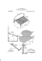
- Figure 1 is a view of my invention .ho ⁇ v-- ing the same as applied for use.
- Fig. 2 is 18 a on an enlarged scale of a portion of the grated comb receiving body.
- Fig. 4 is a perspective view of a portion of the said body and illustrates a slightly modified form of the wire holding bars hereinafter referred to.
- Fig. 5, is a plan of the blank from Whiclrthe casing is bent up.
- a casing which, on the score of shaped or bent up from a tin blank, see Fig. 5. that comprises a back portion 1, a bottom 2,'a front 3 and ends 45-4, the blank being suitably slitted to admit of bending the several parts up to form the style of easing best shown in Fig. 1, it being understood that while I prefer to make the casing of sheet metal bent up to shape, as stated, it-A'nay be otherwise formed.
- the back 1 is formed with an apertured exteniion 10 to hang on a wall, nail or hook, see
- the top of the casing is in the nature of a grated body and as illustrated, it is formed of a plurality of stnands of stout wire, such for example as find piano wire, and in the
- the said strands are, of a stretched on two supporting bars 6? of like length and thickness, prefcrably solid round bars, but may be tubular.
- Bar 6, near one end has a transverse opening and the other bar 7, in practice, has a similar opening disposed diagonally opposite the opening ot the other bar (3 Figs. 3 and 4.
- Fig. 4 it Will be seen 'the grate like body is curing the end of the 'wire 5, through the opening 60 in the bar (5 from which it is stretched to the other bar 7 is wound about said bar in a single coil, as shown in Fig. 4,
- the bars 6-7 may be formed with a plurality of alined spaced notches l171 for receiving the wire coils, see Fig.3, such arrangement providing for an accurate spacing of the wires.
- the grate-like top X may be supported on the casing in various ways, but for sine plieity of structure and ease of application I prefer to mount it as shown in the drawlugs, by reteienee to which it will he noticed the bark and front upper edges of the ends of the casing are notched to form seats -4'(), in which the extreme ends of the bars (3 and T are dropped when fitting the top X in place.
- To hold the top X down are slotted to provide bendable tongues 11 and 20 for clos inn; inwardly over the bars (3 and 7 in. the manner clearly understood from llig. 2, and to catch the droppings or cleanings, a sliding drawer t) is mounted on the casing bolitom, and a deflector plate His bent inwardly from the hack 1 to direct the drop pings over the inner end of the drawer.
- the back 1 has lateral extensions 13 m provided with spring clips 14 to receive the handle end of the brushes as shown in Fig. 1.
- the bar 3 is arranged in a higher plane than the bar 7 so the said grate has an oblique position.
- a reecotacle having two spaced oppositely (positioned supporting seats at its back portion and two spaced oppositely positioned seats at. its front portion,
Landscapes
- Cleaning In General (AREA)
Description
O. N. HARRINGTON.
AUTOMATIC COMB CLEANING HOLDER.
APPLICATION FILED FEB.15,19'09.
Patented Mar. 15, 1910.
' WITNESSES:
glow
" AYTOHNE V5 a transverse section thereof. Fig. 3, plan view "UNITED. STATES PATENT car es.
CLAIIDE N. HARRINGTON, Oi AVON, MINNESOTA.
AUTOMATIC COMB-CLEANING HOLDER.
To all whom" it may concern: 4
Be it known that I, CLAUDE N. HARRING-. TON, residing at Avon, in the county of Stearns and State of Minnesota, have invented a new and Improved Automatic Comb-Cleaning -Holder, of which the following is a specification. As is well known, combs where provided forfree use in public places, for general use in small hotels, railrad stations and like places'are usually unattractive and unsanitary because of the presence of grease, dandruff, hair and other objectionable matter found clogging between the comb teeth.
My invention primarily has for its object to provide a holder orfreceiverfor combs, of a simple, economical and attractive con struction in which special provision is made for holding the comb that-in placing the same on the holder after use and in remov-. ing it therefrom for use, the comb is automatically cleansed of the substances that tend to clog between and upon the comb teeth.
lVith the above and other objects that will hereinafter be referred to, my invention comprehends, in its generic nature, a holder whose comb receiving or body portion is formed with a series of closely arranged slots or spaces, like a grate, adapted for receiving the teeth of the comb therebetween. In its more complete nature, my invention embodies a holder 1n the nature of a casing whose top is;formed of a plurality of closelyheld wire strands, arranged so the teeth of the combs can be conveniently inserted and held therebetween and in such manner that they act as cleaners for removing the substances that clog the teeth, the casing also including a collecting chamber or trough for catching the cleanings as they drop through the grated top.
In its still more subordinate features my invention consists in certain details of. construction, and peculiar combination of parts, all of which will be hereinafter fully described, specifically pointed out in the appended claims and illustrated in the accompanying drawings, iii which:
Figure 1, is a view of my invention .ho\v-- ing the same as applied for use. Fig. 2, is 18 a on an enlarged scale of a portion of the grated comb receiving body. Fig. 4, is a perspective view of a portion of the said body and illustrates a slightly modified form of the wire holding bars hereinafter referred to. Fig. 5, is a plan of the blank from Whiclrthe casing is bent up.
In the practical arrangement of my in-- vention, to provide a neat and attractive device, the same embodies a casing, which, on the score of shaped or bent up from a tin blank, see Fig. 5. that comprises a back portion 1, a bottom 2,'a front 3 and ends 45-4, the blank being suitably slitted to admit of bending the several parts up to form the style of easing best shown in Fig. 1, it being understood that while I prefer to make the casing of sheet metal bent up to shape, as stated, it-A'nay be otherwise formed. The back 1 is formed with an apertured exteniion 10 to hang on a wall, nail or hook, see
The top of the casing is in the nature of a grated body and as illustrated, it is formed of a plurality of stnands of stout wire, such for example as find piano wire, and in the The said strands are, of a stretched on two supporting bars 6? of like length and thickness, prefcrably solid round bars, but may be tubular. Bar 6, near one end has a transverse opening and the other bar 7, in practice, has a similar opening disposed diagonally opposite the opening ot the other bar (3 Figs. 3 and 4. By reference to Fig. 4 it Will be seen 'the grate like body is curing the end of the 'wire 5, through the opening 60 in the bar (5 from which it is stretched to the other bar 7 is wound about said bar in a single coil, as shown in Fig. 4,
simplest form. single member and then carried at a tangent from the bar 7 parallel with strand 50,back over bar 6. is coiled thereover and back to bar 7 again coiled and backwardly and forwardly over the several bars until a complete grated top X for the casing is provided, it being understood that in windlng the wire the bars ll and 7 are to be spaced apart by suitable means.
By winding and spacing the wires on the bars (3 and 7, as stated, an upper and lower grate-like body is formed the two being staggcredly arranged, such provision of two grates having a special advantage since as the combs are impaled on the racks or grato wires the comb teeth as they pass down through the racksare slightly bent or distorted laterally, which not only insures tight gripping or engagement of the comb Specification of Letters Patent. Patented Mar. 15, 1910'. I
economy of manufacture is made by 'sei ioo grated surface of two wire racks,
teeth on the upper and lower Wire members S 50, hut also insures more perfect cleaning of the teeth and a polishing ctt'ect thereon, as the combs are inserted or removed. If desired the bars 6-7 may be formed with a plurality of alined spaced notches l171 for receiving the wire coils, see Fig.3, such arrangement providing for an accurate spacing of the wires.
The grate-like top X may be supported on the casing in various ways, but for sine plieity of structure and ease of application I prefer to mount it as shown in the drawlugs, by reteienee to which it will he noticed the bark and front upper edges of the ends of the casing are notched to form seats -4'(), in which the extreme ends of the bars (3 and T are dropped when fitting the top X in place. To hold the top X down the front and back walls of the casing are slotted to provide bendable tongues 11 and 20 for clos inn; inwardly over the bars (3 and 7 in. the manner clearly understood from llig. 2, and to catch the droppings or cleanings, a sliding drawer t) is mounted on the casing bolitom, and a deflector plate His bent inwardly from the hack 1 to direct the drop pings over the inner end of the drawer.
For col' veniently taking care of the hair brushes, the back 1 has lateral extensions 13 m provided with spring clips 14 to receive the handle end of the brushes as shown in Fig. 1. For convenient] v setting the combs on the grate the bar 3 is arranged in a higher plane than the bar 7 so the said grate has an oblique position.
\Vhlle T have shown and described the.
and a lower, it is obvious but one of such surfaces could be employed for the purposes stated.
From the foregoing it will be apparent bars, a series of W1 that when using my invention even those who have no regard for cleanliness, are compelled to clean the comb they use, through the simple process of taking the comb from, and replz'iring it on the holder since the insertion and removal insures a cleansing ac: tion on the comb teeth.
i i hat I claim is:
1. The combination with the open top casing; having seats in the upper edge of its ends; of a comb cl mer consisting of two 5* strung across from one bar to the other to form a grate,--the ends ol said bars engaging the seats in the ends of the receptacle.
The combination with the open top casing having seals in the upper, edge of its ends; of a comb cleaner consisting of two bars, a series 01" wires strung across from one bar to the other to form a, grate, the ends of said bars engaging the seats in the ends of the rei'zept-zwle, and means that form a part of the receptacle for engaging and locking the said bars in the seats.
3 In a device of the character described, the eoinhiinition with a receptacle, ot' a wire comb supporting rack reniovahly held in top of said receptacle and a tray below said rack. 1
el. 'l n combination, a reecotacle having two spaced oppositely (positioned supporting seats at its back portion and two spaced oppositely positioned seats at. its front portion,
of a bar held by said back seats, a bar held by said front seats, a Wire alternately strun from one bar to the other and bendable members on the front and back portions of the receptacle for engaging the said bars.
. CLA UILE N. HARRINGTON.
iVitnesses I W. ti. lrARlIlOLOMEW H. J. Hannnm
Priority Applications (1)
| Application Number | Priority Date | Filing Date | Title |
|---|---|---|---|
| US47797809A US952328A (en) | 1909-02-15 | 1909-02-15 | Automatic comb-cleaning holder. |
Applications Claiming Priority (1)
| Application Number | Priority Date | Filing Date | Title |
|---|---|---|---|
| US47797809A US952328A (en) | 1909-02-15 | 1909-02-15 | Automatic comb-cleaning holder. |
Publications (1)
| Publication Number | Publication Date |
|---|---|
| US952328A true US952328A (en) | 1910-03-15 |
Family
ID=3020738
Family Applications (1)
| Application Number | Title | Priority Date | Filing Date |
|---|---|---|---|
| US47797809A Expired - Lifetime US952328A (en) | 1909-02-15 | 1909-02-15 | Automatic comb-cleaning holder. |
Country Status (1)
| Country | Link |
|---|---|
| US (1) | US952328A (en) |
-
1909
- 1909-02-15 US US47797809A patent/US952328A/en not_active Expired - Lifetime
Similar Documents
| Publication | Publication Date | Title |
|---|---|---|
| US1226231A (en) | Holder for toilet articles. | |
| US1972532A (en) | Holder for toothbrushes | |
| US1182732A (en) | Spoon-holder. | |
| US955646A (en) | Paint-brush holder. | |
| US1242956A (en) | Brush and glass holder. | |
| US1194540A (en) | Tahako | |
| US872091A (en) | Tooth-brush holder. | |
| US1546548A (en) | Combination brush and comb cleaner and holder | |
| US1356487A (en) | Toothbrush-holder | |
| US1211353A (en) | Soap-receptacle. | |
| US1713275A (en) | Household utensil | |
| US1053103A (en) | Milk-bottle holder. | |
| US2036807A (en) | Rake | |
| US1993460A (en) | Toothbrush and tumbler holder | |
| US642780A (en) | Combined holder. | |
| US2439873A (en) | Combined bird cage perch cleaner and holder for mite attracting material | |
| US540129A (en) | George j | |
| US883402A (en) | Tray attachment for blackboards. | |
| US1055488A (en) | Combination brush and comb holder. | |
| US880855A (en) | Flue-cleaner. | |
| US1422788A (en) | Comb cleaner | |
| US1291028A (en) | Comb cleaner and holder. | |
| US972709A (en) | Pad-holder. | |
| US248489A (en) | Toilet-article holder | |
| US4803750A (en) | Fork and comb cleaning tool |