US972709A - Pad-holder. - Google Patents
Pad-holder. Download PDFInfo
- Publication number
- US972709A US972709A US47713809A US1909477138A US972709A US 972709 A US972709 A US 972709A US 47713809 A US47713809 A US 47713809A US 1909477138 A US1909477138 A US 1909477138A US 972709 A US972709 A US 972709A
- Authority
- US
- United States
- Prior art keywords
- pad
- holder
- wire
- frame
- bent
- Prior art date
- Legal status (The legal status is an assumption and is not a legal conclusion. Google has not performed a legal analysis and makes no representation as to the accuracy of the status listed.)
- Expired - Lifetime
Links
- 238000010276 construction Methods 0.000 description 3
- 230000000284 resting effect Effects 0.000 description 1
- 210000001364 upper extremity Anatomy 0.000 description 1
Images
Classifications
-
- B—PERFORMING OPERATIONS; TRANSPORTING
- B42—BOOKBINDING; ALBUMS; FILES; SPECIAL PRINTED MATTER
- B42D—BOOKS; BOOK COVERS; LOOSE LEAVES; PRINTED MATTER CHARACTERISED BY IDENTIFICATION OR SECURITY FEATURES; PRINTED MATTER OF SPECIAL FORMAT OR STYLE NOT OTHERWISE PROVIDED FOR; DEVICES FOR USE THEREWITH AND NOT OTHERWISE PROVIDED FOR; MOVABLE-STRIP WRITING OR READING APPARATUS
- B42D5/00—Sheets united without binding to form pads or blocks
- B42D5/04—Calendar blocks
- B42D5/043—Supports for desk-type calendars or diaries
-
- Y—GENERAL TAGGING OF NEW TECHNOLOGICAL DEVELOPMENTS; GENERAL TAGGING OF CROSS-SECTIONAL TECHNOLOGIES SPANNING OVER SEVERAL SECTIONS OF THE IPC; TECHNICAL SUBJECTS COVERED BY FORMER USPC CROSS-REFERENCE ART COLLECTIONS [XRACs] AND DIGESTS
- Y10—TECHNICAL SUBJECTS COVERED BY FORMER USPC
- Y10S—TECHNICAL SUBJECTS COVERED BY FORMER USPC CROSS-REFERENCE ART COLLECTIONS [XRACs] AND DIGESTS
- Y10S24/00—Buckles, buttons, clasps
- Y10S24/08—Paper clips
- Y10S24/10—Wire
Definitions
- PAD HOLDER. APPLICATION FILED 23.10, 1909.
- the invention relates to pad holders and is more particularly designed for use in holding desk calendars.
- the invention consists in the construction as hereinafter set forth.
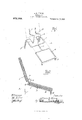
- Figure 1 is a perspective view of the holder; and Fig. 2 is a side elevation of the same, in use.
- My improved holder consists of a wire frame and is preferably formed from a single piece of wire bent to form the various elements of the structure.
- the body portion of this frame consists of a substantially rectangular frame of a size to receive and support the pad, being provided with downwardly-extending legs of different lengths at the opposite ends, whereby the frame is held in inclined positions.
- A is the body portion of the frame consisting of two substantially rectangular portions B and C connected to each other by the central double-strand twisted section D.
- This central section D as well as the adjacent sides of the rectangular portions B and C, form a firm support for the 1
- the front legs E are formed by downwardly-bent loops at the corners of the rectangular portion B, while the rear legs are similarly formed of downwardly-bent loops F, which are of greater length than the loops E, and are arranged at the outer corners of the rectangular portion C. From these legs F the wire is bent inwardly and then upwardly to form the prongs G which engage apertures in the pad and secure the latter to the holder.
- These prongs G are further provided with rearward angular extensions H, terminating in upward extensions I which form the support for the detached leaves from the pad.
- the pad With the construction as described in use the pad may be engaged with the holder, by inserting the ends I of the prongs in the ap ertures in the pad, and then moving the latter around the bends, until it rests upon the body frame A. WVhere the total thickness of the pad is considerable, as for instance, with a calendar having a separate leaf for each day, it may be desirable to employ a series of pad sections separately bound, and which may be more conveniently turned around the bends of the wire. WVhen once engaged, the pad is firmly supported upon the frame and whenever a leaf is detached it may be moved around the bend between the sections G and H and supported by resting against the upward extension I. In this position it forms no obstruction to the body portion of the pad, but is in a position where it is accessible at any time for reference.
- a pad holder comprising a wire frame consisting of adjacent open center sections, with an intermediate double-strand twisted section, legs formed by depending loops at the corners of said open centered sections, and a prong formed by the end portion of the wire.
- a pad holder comprising a wire frame formed from a single piece of wire bent to form open center sections spaced apart and connected centrally of the adjacent sides, legs formed by depending loops at the corners of the sections, the opposite ends of the wire being bent to form prongs.
Landscapes
- Respiratory Apparatuses And Protective Means (AREA)
Description
E. H. NELSON.
PAD HOLDER. APPLICATION FILED 23.10, 1909.
972,709., Patented 0ct.11,1910.
SATES ATENT OFFC.
EDWIN H. NELSON, OF DETROIT, MICHIGAN.
PAD-HOLDER.
Specification of Letters Patent.
Patented oet. 11, 1910.
To all whom it may concern:
Be it known that I, EDWIN I-I. NELSON, a citizen of the United States of America, residing at Detroit, in the county of-Wayne and State of Michigan, have invented certain new and useful Improvements in Pad- I-Iolders, of which the following is a specification, reference being had therein to the accompanying drawings.
The invention relates to pad holders and is more particularly designed for use in holding desk calendars.
It is the object of the invention to obtain a simple and inexpensive construction and one which is capable not only of holding the pad, but also permits of removing the leaves which are preserved for reference.
To this end, the invention consists in the construction as hereinafter set forth.
In the drawings-Figure 1 is a perspective view of the holder; and Fig. 2 is a side elevation of the same, in use.
My improved holder consists of a wire frame and is preferably formed from a single piece of wire bent to form the various elements of the structure. The body portion of this frame consists of a substantially rectangular frame of a size to receive and support the pad, being provided with downwardly-extending legs of different lengths at the opposite ends, whereby the frame is held in inclined positions.
In detail, A is the body portion of the frame consisting of two substantially rectangular portions B and C connected to each other by the central double-strand twisted section D. This central section D, as well as the adjacent sides of the rectangular portions B and C, form a firm support for the 1 The front legs E are formed by downwardly-bent loops at the corners of the rectangular portion B, while the rear legs are similarly formed of downwardly-bent loops F, which are of greater length than the loops E, and are arranged at the outer corners of the rectangular portion C. From these legs F the wire is bent inwardly and then upwardly to form the prongs G which engage apertures in the pad and secure the latter to the holder. These prongs G are further provided with rearward angular extensions H, terminating in upward extensions I which form the support for the detached leaves from the pad.
With the construction as described in use the pad may be engaged with the holder, by inserting the ends I of the prongs in the ap ertures in the pad, and then moving the latter around the bends, until it rests upon the body frame A. WVhere the total thickness of the pad is considerable, as for instance, with a calendar having a separate leaf for each day, it may be desirable to employ a series of pad sections separately bound, and which may be more conveniently turned around the bends of the wire. WVhen once engaged, the pad is firmly supported upon the frame and whenever a leaf is detached it may be moved around the bend between the sections G and H and supported by resting against the upward extension I. In this position it forms no obstruction to the body portion of the pad, but is in a position where it is accessible at any time for reference.
If the sides of the stand were formed uninterrupted from one end to the other, rather heavy wire would be required in order to give the stand the desired rigidity. This difiiculty is overcome however, by connecting the two rectangular portions by the twisted portion D, the latter forming a sort of a brace or support for the central portion of the stand.
What I claim as my invention is:
1. A pad holder comprising a wire frame consisting of adjacent open center sections, with an intermediate double-strand twisted section, legs formed by depending loops at the corners of said open centered sections, and a prong formed by the end portion of the wire.
2. A pad holder comprising a wire frame formed from a single piece of wire bent to form open center sections spaced apart and connected centrally of the adjacent sides, legs formed by depending loops at the corners of the sections, the opposite ends of the wire being bent to form prongs. v
In testimony whereof I aflix my signature in presence of two witnesses.
EDWVIN H. NELSON.
Witnesses W. J. BELKNAP, JAMEs P. BARRY.
Priority Applications (1)
| Application Number | Priority Date | Filing Date | Title |
|---|---|---|---|
| US47713809A US972709A (en) | 1909-02-10 | 1909-02-10 | Pad-holder. |
Applications Claiming Priority (1)
| Application Number | Priority Date | Filing Date | Title |
|---|---|---|---|
| US47713809A US972709A (en) | 1909-02-10 | 1909-02-10 | Pad-holder. |
Publications (1)
| Publication Number | Publication Date |
|---|---|
| US972709A true US972709A (en) | 1910-10-11 |
Family
ID=3041089
Family Applications (1)
| Application Number | Title | Priority Date | Filing Date |
|---|---|---|---|
| US47713809A Expired - Lifetime US972709A (en) | 1909-02-10 | 1909-02-10 | Pad-holder. |
Country Status (1)
| Country | Link |
|---|---|
| US (1) | US972709A (en) |
Cited By (2)
| Publication number | Priority date | Publication date | Assignee | Title |
|---|---|---|---|---|
| US4611719A (en) * | 1984-08-16 | 1986-09-16 | Dudek D Ann | Holder for working with computer print-outs |
| US4828118A (en) * | 1987-06-18 | 1989-05-09 | Dearien Jr John A | Continuous paper feeder and collector |
-
1909
- 1909-02-10 US US47713809A patent/US972709A/en not_active Expired - Lifetime
Cited By (2)
| Publication number | Priority date | Publication date | Assignee | Title |
|---|---|---|---|---|
| US4611719A (en) * | 1984-08-16 | 1986-09-16 | Dudek D Ann | Holder for working with computer print-outs |
| US4828118A (en) * | 1987-06-18 | 1989-05-09 | Dearien Jr John A | Continuous paper feeder and collector |
Similar Documents
| Publication | Publication Date | Title |
|---|---|---|
| US710477A (en) | Valance-hanger for bedsteads. | |
| US933517A (en) | Letter-tray. | |
| JP2024099585A5 (en) | ||
| US231969A (en) | Pen-rack | |
| US972709A (en) | Pad-holder. | |
| US941653A (en) | Foldable kitchen-rack. | |
| US1064734A (en) | Towel-rack. | |
| US202959A (en) | Improvement in book-supports | |
| US918045A (en) | Easel. | |
| US1669065A (en) | Serving tray | |
| US1041563A (en) | Curtain-fixture. | |
| US769141A (en) | Curtain-pole. | |
| US965707A (en) | Towel-holder. | |
| US773979A (en) | Clasp. | |
| US2012422A (en) | Retaining device | |
| US982795A (en) | Attachment for telephone-desks. | |
| US363511A (en) | William | |
| US1035989A (en) | Curtain-rod. | |
| US781890A (en) | Book-supporter. | |
| US2236045A (en) | Support | |
| US2205908A (en) | Ornamental device | |
| US1050519A (en) | Rack for umbrellas and other articles. | |
| US1487586A (en) | Memorandum-pad holder | |
| US1441323A (en) | Abacus frame | |
| US379152A (en) | Hat and coat rack |