US9518928B2 - Optode for determining chemical parameters - Google Patents
Optode for determining chemical parameters Download PDFInfo
- Publication number
- US9518928B2 US9518928B2 US14/373,397 US201314373397A US9518928B2 US 9518928 B2 US9518928 B2 US 9518928B2 US 201314373397 A US201314373397 A US 201314373397A US 9518928 B2 US9518928 B2 US 9518928B2
- Authority
- US
- United States
- Prior art keywords
- optode
- sensitive
- dye
- immobilized
- sensor
- Prior art date
- Legal status (The legal status is an assumption and is not a legal conclusion. Google has not performed a legal analysis and makes no representation as to the accuracy of the status listed.)
- Active, expires
Links
- 0 *OC1=CC=C(OC2=CC=C(C(=O)C3=CC=C(OC4=C(S(=O)(=O)O)C=C(OC5=CC=C(C(=O)C6=CC=C(*)C=C6)C=C5)C=C4)C=C3)C=C2)C=C1 Chemical compound *OC1=CC=C(OC2=CC=C(C(=O)C3=CC=C(OC4=C(S(=O)(=O)O)C=C(OC5=CC=C(C(=O)C6=CC=C(*)C=C6)C=C5)C=C4)C=C3)C=C2)C=C1 0.000 description 1
- NEVZJZZWQGDQCJ-UHFFFAOYSA-N COc1ccc(Oc2ccc(C(=O)c3ccc(C)cc3)cc2)c(S(=O)(=O)O)c1 Chemical compound COc1ccc(Oc2ccc(C(=O)c3ccc(C)cc3)cc2)c(S(=O)(=O)O)c1 NEVZJZZWQGDQCJ-UHFFFAOYSA-N 0.000 description 1
Images


Classifications
-
- G—PHYSICS
- G01—MEASURING; TESTING
- G01N—INVESTIGATING OR ANALYSING MATERIALS BY DETERMINING THEIR CHEMICAL OR PHYSICAL PROPERTIES
- G01N21/00—Investigating or analysing materials by the use of optical means, i.e. using sub-millimetre waves, infrared, visible or ultraviolet light
- G01N21/75—Systems in which material is subjected to a chemical reaction, the progress or the result of the reaction being investigated
- G01N21/77—Systems in which material is subjected to a chemical reaction, the progress or the result of the reaction being investigated by observing the effect on a chemical indicator
- G01N21/78—Systems in which material is subjected to a chemical reaction, the progress or the result of the reaction being investigated by observing the effect on a chemical indicator producing a change of colour
- G01N21/80—Indicating pH value
-
- G—PHYSICS
- G01—MEASURING; TESTING
- G01N—INVESTIGATING OR ANALYSING MATERIALS BY DETERMINING THEIR CHEMICAL OR PHYSICAL PROPERTIES
- G01N21/00—Investigating or analysing materials by the use of optical means, i.e. using sub-millimetre waves, infrared, visible or ultraviolet light
- G01N21/62—Systems in which the material investigated is excited whereby it emits light or causes a change in wavelength of the incident light
- G01N21/63—Systems in which the material investigated is excited whereby it emits light or causes a change in wavelength of the incident light optically excited
- G01N21/64—Fluorescence; Phosphorescence
- G01N21/6408—Fluorescence; Phosphorescence with measurement of decay time, time resolved fluorescence
-
- G—PHYSICS
- G01—MEASURING; TESTING
- G01N—INVESTIGATING OR ANALYSING MATERIALS BY DETERMINING THEIR CHEMICAL OR PHYSICAL PROPERTIES
- G01N21/00—Investigating or analysing materials by the use of optical means, i.e. using sub-millimetre waves, infrared, visible or ultraviolet light
- G01N21/62—Systems in which the material investigated is excited whereby it emits light or causes a change in wavelength of the incident light
- G01N21/63—Systems in which the material investigated is excited whereby it emits light or causes a change in wavelength of the incident light optically excited
- G01N21/64—Fluorescence; Phosphorescence
- G01N21/6428—Measuring fluorescence of fluorescent products of reactions or of fluorochrome labelled reactive substances, e.g. measuring quenching effects, using measuring "optrodes"
- G01N21/643—Measuring fluorescence of fluorescent products of reactions or of fluorochrome labelled reactive substances, e.g. measuring quenching effects, using measuring "optrodes" non-biological material
-
- G—PHYSICS
- G01—MEASURING; TESTING
- G01N—INVESTIGATING OR ANALYSING MATERIALS BY DETERMINING THEIR CHEMICAL OR PHYSICAL PROPERTIES
- G01N21/00—Investigating or analysing materials by the use of optical means, i.e. using sub-millimetre waves, infrared, visible or ultraviolet light
- G01N21/62—Systems in which the material investigated is excited whereby it emits light or causes a change in wavelength of the incident light
- G01N21/63—Systems in which the material investigated is excited whereby it emits light or causes a change in wavelength of the incident light optically excited
- G01N21/64—Fluorescence; Phosphorescence
- G01N21/6428—Measuring fluorescence of fluorescent products of reactions or of fluorochrome labelled reactive substances, e.g. measuring quenching effects, using measuring "optrodes"
- G01N2021/6434—Optrodes
-
- G—PHYSICS
- G01—MEASURING; TESTING
- G01N—INVESTIGATING OR ANALYSING MATERIALS BY DETERMINING THEIR CHEMICAL OR PHYSICAL PROPERTIES
- G01N21/00—Investigating or analysing materials by the use of optical means, i.e. using sub-millimetre waves, infrared, visible or ultraviolet light
- G01N21/62—Systems in which the material investigated is excited whereby it emits light or causes a change in wavelength of the incident light
- G01N21/63—Systems in which the material investigated is excited whereby it emits light or causes a change in wavelength of the incident light optically excited
- G01N21/64—Fluorescence; Phosphorescence
- G01N21/6428—Measuring fluorescence of fluorescent products of reactions or of fluorochrome labelled reactive substances, e.g. measuring quenching effects, using measuring "optrodes"
- G01N2021/6439—Measuring fluorescence of fluorescent products of reactions or of fluorochrome labelled reactive substances, e.g. measuring quenching effects, using measuring "optrodes" with indicators, stains, dyes, tags, labels, marks
-
- G—PHYSICS
- G01—MEASURING; TESTING
- G01N—INVESTIGATING OR ANALYSING MATERIALS BY DETERMINING THEIR CHEMICAL OR PHYSICAL PROPERTIES
- G01N2201/00—Features of devices classified in G01N21/00
- G01N2201/06—Illumination; Optics
- G01N2201/061—Sources
- G01N2201/06113—Coherent sources; lasers
- G01N2201/0612—Laser diodes
-
- G—PHYSICS
- G01—MEASURING; TESTING
- G01N—INVESTIGATING OR ANALYSING MATERIALS BY DETERMINING THEIR CHEMICAL OR PHYSICAL PROPERTIES
- G01N2201/00—Features of devices classified in G01N21/00
- G01N2201/08—Optical fibres; light guides
Definitions
- Subject of the present invention is an optode for determining the chemical parameters of a sensor as well as a method for determining chemical parameters using the optode in accordance with this invention.
- Chemical parameters in the context of this invention are understood to be pH value and the concentration of substances.
- Chemical sensors are components which provide an analytically evaluable signal from chemical information.
- Optodes are probes which demonstrate visually the presence of chemical substances or indicate chemical parameters with the aid of a sensor dye.
- the use is made of the fact that the optical properties of sensor dyes, for example their luminescence, change in the presence of the substance to be detected or its chemical parameters.
- the spectrum of possible areas of application ranges from determining conditions in individual cells via foodstuff and bioreactor monitoring to supervision of underground and process plants, e.g. geothermal or crude oil drilling.
- optical fiber cables are a great advantage in technical applications where great distances are involved, sometimes kilometers, between the measuring station and the actual sample.
- optodes are already state-of-the-art in determining pH and other chemical parameters such as oxygen concentration. Optodes have already been described that allow the determination of several chemical parameters. In evaluating the suitability of optodes for implementation, the optical measurement method most suited to optodes must be taken into consideration. In this, a differentiation has to be made as to whether the optodes are suitable for both stationary and time-resolved optical methods.
- Stationary methods can be used to determine the change in luminescence intensity of a sensor dye as a function of the change in analytic concentration. For this, the sensor dyes are excited as far as possible at the maximum of the absorption bands and emission spectra for different analytical concentrations. The evaluation of the luminous intensity at certain emission wavelengths results in a function which is dependent on the concentration of the analyte.
- time domain spectroscopy TD-S
- decay time a further specific property of the dye is determined—the decay time.
- the decay time is the time taken by the luminescence intensity to fall to a given percentage of its original value.
- the term “luminescence” will be used in the context of the present invention as a blanket term for fluorescence and phosphorescence.
- a great advantage of the decay time determination is that it is largely independent of the dye concentration within the sensor matrix and of fluctuations in the intensity of the excitation source.
- Time-resolved methods also supply, in addition to the stationary intensity change, the time-dependent absorption of the luminescence intensity after excitation by a short light pulse.
- Phase-modulation spectroscopy is one of the methods in which the decay time of a sensor dye is determined. This allows real-time measurements due to the fast response times of the sensors ( ⁇ 10 s) and a fast measurement technique. Also, very small signal intensities suffice without this having an effect on the accuracy of the measurement.
- the determination of two or more parameters is also desirable in various areas.
- the particular case of simultaneous determination of several chemical parameters is of great interest.
- the possibility of determining several parameters using one measurement makes the analytics not only more cost effective but also faster. Also, less material is required in the sample, which is important—especially in medical applications.
- This bifunctional sensor dye is integrated into a matrix of polyvinylchloride and bis-(2-ethylhexyl)sebacate.
- a discussion takes place about the use of more than one sensor dye in a sensor possibly leading to interactions and an overlapping of the suitable spectral ranges.
- the pH value with the disclosed optode is determined, or can be determined, by means of the decay time of the sensor dye.
- the multioptodes described by Borchert et al. enable the measurement of pH in the range 5 to 9. The measurement of lower pH values is nor revealed.
- Nivens et al. An optode, which can determine pH and, after the attachment of a further matrix, is also suitable for determining concentrations of carbon dioxide and ammonia, is described by Nivens et al. (D. A. Nivens et al., “Multilayer sol-gel membranes for optical sensing applications: single layer pH and dual layer CO 2 and NH 3 sensors”, Talanta 2002, 58, 543-550.
- a sensor for measuring pH which includes a base-catalyzed sol-gel into which the indicator hydroxypyrene trisulfonic acid has been introduced. This sensor can be used to determine the pH value. If CO 2 or NH 3 concentrations are to be measured with this sensor, a further layer is applied on top of the sol-gel layer of the pH sensor, the latter being a hydrophobic sol-gel layer. This is to prevent interactions. A simultaneous determination of several chemical parameter is not revealed in the publication named. The measurement of the luminescence decay time of the pH-sensitive dye is also not revealed.
- state-of-the-art pH-sensitive optodes can be based on the measurement of pH-dependent, stationary fluorescence intensity (see: J. Lin, “Recent development and applications of optical and fiber-optic pH sensors”, Trends in analytical chemistry 2000, 19, 541-551).
- No optical probe is described as state-of-the-art, which consists of a pH-sensitive dye, immobilized in a matrix and which enables a pH measurement via determination of the luminescence decay time of the pH-sensitive dye.
- pH-sensitive dyes are normally immobilized in water-permeable polymers. With combinations of polymer matrix and sensor dye used up to now, changes on the optical properties of pH-sensitive dyes have occurred which severely restrict the usefulness of the corresponding optodes. These changes in the optical properties result in these state-of-the-art optodes losing the property of change in the fluorescence decay time of the pH-sensitive dye as a function of pH value. A direct measurement of pH via the decay time of a pH-sensitive dye is therefore impossible.
- the measurement of the decay time has the important advantage that it is almost completely independent of the dye concentration within the sensor matrix and of fluctuations in intensity of the excitation source.
- Loss of change in decay time as a function of pH value also then makes the use of special spectroscopic methods such as phase modulation spectroscopy impossible.
- the dual state-of-the-art optodes for measuring pH and oxygen concentration also possess a pH measuring range from 5 to 7.5. The usefulness of these optodes is limited by this measuring range.
- the purpose of this present invention is to eliminate the disadvantages of these state-of-the-art devices.
- the purpose of the present invention is therefore to provide optodes with which the luminescence decay time of a pH-sensitive dye as a function of pH is retained—even after immobilizing the sensor dye in a polymer matrix.
- the purpose of the present invention is also to provide optodes which, in addition to determining the pH, allow the determination of further chemical parameters, especially as a simultaneous measurement. In this, the optode for spatially resolved, real-time measurement shall be used.
- an optode for determining chemical parameters of a sample wherein the optode consists of a polymer matrix which consists of sulfonated polyether ether ketone (SPEEK) in which a sensor dye is immobilized or more than one sensor dye is immobilized, wherein at least one of the immobilized sensor dyes is pH-sensitive.
- SPEEK sulfonated polyether ether ketone
- an optode with which in the sulfonated polyether ether ketone (SPEEK) at least one further sensor dye is immobilized.
- SPEEK sulfonated polyether ether ketone
- Preferred is also an invention-related optode that consists of at least one further polymer matrix, in which at least one further sensor dye is immobilized
- At least one further sensor dye is selected from oxygen-sensitive, halide ion-sensitive, sodium ion-sensitive, potassium ion-sensitive, pH-sensitive and calcium ion-sensitive dyes.
- an optode with which the oxygen sensitive dye selected is from Pt(II)meso-tetra(pentafluorophenyl)porphyrin (Pt-TPFPP), Pd(II)meso-tetra(pentafluorophenyl)porphyrin and ruthenium(II)-tris(4,7-diphenyl-1,10-phenanthroline)perchlorate (Ru-pCl) and ruthenium(II)-tris(4,7-diphenyl-1,10-phenanthroline)dichloride;
- Pt-TPFPP Pt(II)meso-tetra(pentafluorophenyl)porphyrin
- Ru-pCl ruthenium(II)-tris(4,7-diphenyl-1,10-phenanthroline)dichloride
- the halide ion-sensitive dye selected is from the chloride ion-sensitive dyes N,N′-dimethyl-9,9′-bis-acridinium nitrate (Lucigenin), 6-methoxy-N-(3-sulfopropyl)quinolinium (SPQ) and N-(ethoxycarbonylmethyl)-6-methoxy-quinolinium bromide (MQAE);
- the sodium ion-sensitive dye selected is from N,N′-[1,4,10-trioxa-7,13-diazacyclopentadecane-7,13-diylbis(2,5-dimethoxy-4,1-phenylene)]bis[3′,6′-bis(acetyloxy)-2′,7′-dichloro-3-oxo-spiro[isobenzofuran-1(3H),9′-[9H]xanthen]-5-carboxamide, (Sodium Green®, Molecular Probes, CAS Registry-Number 159952-49-5) and N-(4-[1-(7-diethylaminocoumarin-3-yl)-1H-1,2,3-triazol-4yl]phenylaza-18-crown-6-ether;
- the potassium-sensitive dye is N-(2-methoxyethoxy)phenylaza-18-crown-6)-4-(coumarinyl)-1H-1,2,3-triazol
- the calcium ion-sensitive dye is selected from the calcium ion-sensitive dye N-[2-[(acetyloxy)methoxy]-2-oxoethyl]-N-[4-[[[3′,6′-bis(acetyloxy)-2′,7′-difluoro-3-oxospiro[isobenzofuran-1(3H),9′-[9H]xanthen]-5-yl]carbonyl]amino]-2-[2-[2-[bis[2-[(acetyloxy)methoxy]-2-oxoethyl]amino]phenoxy]ethoxy]phenyl]-glycine-(acetyloxy)methyl ester (Oregon GreenTM 488 BAPTA-1), N-[2-[2-[2-[2-[2-[2-[bis(carboxymethyl)amino]-5-[[(2′,7′-difluoro-3′,6′-dihydroxy-3-oxo
- an optode with which the polymer of at least one further polymer matrix is selected from poly(2,2,2-trifluoroethylmethacrylate (P1), poly(2-hydroxypropylmethacrylate) (PHPMA), poly(2-hydroxyethylmethacrylate) (PHEMA), polyurethane (PU), polyvinylpyrrolidone (PVP), poly(1-vinylpyrrolidone)-co-styrene (PVPS), polyvinylchloride (PVC), polyacrylonitrile-polyacrylamide-blockcopolymer (HYPAN HN 80) and polystyrene.
- P1 poly(2-hydroxypropylmethacrylate)
- PHEMA poly(2-hydroxyethylmethacrylate)
- PU polyurethane
- PVP polyvinylpyrrolidone
- PVPS poly(1-vinylpyrrolidone)-co-styrene
- PVC polyvinylch
- Invention-related special preference is an optode with which the pH-sensitive dye is 6-carboxyfluorescein (CF) or 5(6)-Carboxy-2,7′-dichlorofluorescein (Cl-CF), the further polymer is a poly(2,2,2-trifluoroethylmethacrylate)matrix and the oxygen-sensitive dye is Pt(II)meso-tetra(pentafluorophenyl)porphyrin or Pd(II)meso-Tetra(pentafluorophenyl)porphyrin.
- the pH-sensitive dye is 6-carboxyfluorescein (CF) or 5(6)-Carboxy-2,7′-dichlorofluorescein (Cl-CF)
- the further polymer is a poly(2,2,2-trifluoroethylmethacrylate)matrix
- the oxygen-sensitive dye is Pt(II)meso-tetra(pentafluorophenyl
- an optode which consists of two further polymer matrices, wherein the first further matrix includes the polymer poly(2-hydroxypropylmethacrylate), in which the chloride ion-sensitive dye N,N′-dimethyl-9,9′-bisacridiniumnitrate is immobilized, and the second further polymer matrix includes the polymer poly(2,2,2-trifluoroethylmethacrylate), in which the oxygen-sensitive dye Pt(II)meso-tetra(pentafluorophenyl)porphyrin (Pt-TPFPP) oder Pd(II)meso-Tetra(pentafluorophenyl)porphyrin (Pd-TPFPP) is immobilized.
- the first further matrix includes the polymer poly(2-hydroxypropylmethacrylate), in which the chloride ion-sensitive dye N,N′-dimethyl-9,9′-bisacridiniumnitrate is immobilized
- an optode with which the at least one substrate is selected from glass substrates or polymer substrates.
- an optode in which the substrate is formed from a polymer matrix in which a sensor dye is immobilized.
- Advantageous in invention terms is an implementation form which is connected to one or more fiber optic conductors or part of a fiber optic conductor.
- the purpose of the present invention is also satisfied by a method for determining the pH of a sample in which the invention-related optode is used.
- a method with which, in addition, carbon dioxide concentration and/or ammonia concentration and/or oxygen concentration and/or halide ion concentration and/or sodium ion concentration and/or potassium ion concentration and/or calcium ion concentration of the sample can be determined and the determination of the parameters can be performed simultaneously or time-shifted.
- SPEEK sulfonated polyether ether ketone
- the immobilizing of a further sensor dye in the SPEEK matrix of the invention-related optode enables the determination of further chemical parameters and also the determination of pH in different pH ranges by combining various pH-sensitive dyes. This therefore reduces the technical effort required when compared with the use of several individual optodes.
- the immobilization of a further sensor dye in a further polymer matrix has the advantage that further parameters of the sample, in addition to the pH, can be determined using one optode.
- the further polymer matrix can be individually adapted to the other parameters to be measured and to the immobilized sensor dye.
- the determination of a gas concentration requires a polymer matrix that is permeable to gas. It can also be an advantage, depending on the sensor dye, to use a polymer material that has an adapted polarity.
- the possibility of immobilizing different pH-sensitive sensor dyes in the invention-related optode enables measurement in different pH ranges while retaining the invention-related benefits.
- the invention-related optode can be adapted in its sensitivity and measuring range to different substance concentrations.
- the large number of polymers that can be used as a further polymer matrix makes possible the adaptation of the invention-related optode to the parameters to be measured and the sensor dyes used. This makes possible an individual tuning of the optode to the area of application.
- the optode can be combined with a suitable carrier, depending on the range of the application.
- Carriers can be made from a wide variety of materials, for example glass or polymers.
- glass carriers can for example be a planar glass body such as a slide and the optode material can be deposited as a film on the carrier.
- separating layers do not contain sensor dyes.
- separating layers can be of advantage in the measurement of carbon dioxide and ammonia concentrations using the invention-related optode.
- a material layer that is gas-permeable but water-impermeable can be applied on the SPEEK/pH-sensor dye object. The determination of carbon dioxide and ammonia concentrations can then take place by measuring the pH, without falsification of the result from non-gaseous media, e.g. liquids in the surroundings.
- the optode material can be arranged for example on the tip of a fiber of the light conductor. It is however also preferred that the optode material is arranged on several fibers of a conductor so that measurements are possible at different positions in a sample.
- the invention-related optode consists of more than one polymer material in which a sensor dye is immobilized, the polymer/dye layers can be deposited in any order on the carrier.
- the invention-related optode for determining several parameters can also be applied to the carrier in such a way that the optode material is not applied in successive layers on a carrier but only in spatial proximity to each other. Spatial proximity here means that the arrangement enables a simultaneous measurement of both parameters.
- SPEEK containing the immobilized sensor dye is applied to the fiber and the further polymer matrix is arranged on the fiber next to this optode material. Overlapping of the layers can occur here or the attachment of the further polymer matrix can take place without overlapping.
- a glass fiber it is preferred to coat the ends of a glass fiber with the optode material components so that, for example, one fiber carries the SPEEK matrix for determining pH and one or more further fibers the polymer matrices for determining the further parameter or parameters.
- the optode material can be applied to a polymer carrier, for example in the form of a polymer particle such as polymer beads.
- an optode material component i.e. a polymer matrix with immobilized sensor dye serves itself as carrier for further polymer/sensor dye combinations.
- an optode material component i.e. a polymer matrix with immobilized sensor dye serves itself as carrier for further polymer/sensor dye combinations.
- the optode can be inserted directly into the sample in the form of a polymer particle.
- the process to be investigated can be followed from outside by optical interrogation of the bead-shaped probe.
- the optical signal can be detected here by means of a microscope or optical fibers.
- SPEEK Sulfonated Poly(Ether Ether Ketone)
- SPEEK sulfonated poly ether ether ketone
- polyether ether ketone PEEK
- PEEK polyether ether ketone
- the degree of sulfonation DS is set by the choice of reaction temperature and reaction time.
- the degree of sulfonation is the ratio of concentration of sulfonated PEEK repeat units (see Formula 1) to the concentration of the entire initial PEEK repeat units.
- SPEEK with a 40 to 80% degree of sulfonation was used.
- Formula 2 shows SPEEK with a degree of sulfonation under 100%.
- Ormosil was synthesized according to I. Klimant et al., “Fast response oxygen micro-optodes based on novel soluble ormosil glasses”, Mikrochim. Acta 1999, 131, 35-46;
- HYPAN HN 80 hydrogel, (CAS Registry No. 167290-73-5) block copolymer from polyacrylonitrile and polyacrylamide;
- SiO 2 (Aerosil R972, Degussa, CAS Registry No. 60842-32-2)
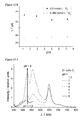
- FIG. 1 shows the calibration of an optode for determination of oxygen concentration in the example of the oxygen-sensitive Pd sensor (palladium(II)-meso-tetra(pentafluorophenyl)porphyrin, immobilized in poly(2,2,2-trifluoroethylmethacrylate) (P1)), and a ruthenium-based sensor (ruthenium(II)-tris(4,7-diphenyl-1,10-phenanthroline)-perchlorate immobilized in polystyrene beads);
- FIG. 2 B shows the average decay time, calculated from the results of biexponential fits
- FIG. 3 B shows the average decay time, calculated from results of biexponential fits;
- FIG. 5 B shows the intensity ratio when evaluating at various emission wavelengths
- FIG. 6 B shows the intensity ratio (quotient) when evaluating at various emission wavelengths
- FIG. 7 B shows the evaluation of the intensity at various emission wavelengths.
- FIG. 12 A shows the decay times of Pt-TPFPP immobilized in P1 as a function of oxygen concentration
- FIG. 13 A shows the measurement at 21 vol % oxygen
- FIG. 13 B shows the measurement at 0 vol % oxygen
- FIG. 15 shows the evaluation of the emission spectra of the invention-related dual-optode for determining pH value and oxygen concentration;
- FIG. 15 A shows the pH signal at various wavelengths and O 2 concentrations,
- FIG. 15 B shows the Stern-Volmer graph of intensities at 650 nm for various pH values.
- FIG. 16 shows calibrations of the invention-related dual-optode for determining pH value and oxygen concentration
- FIG. 17 A shows the decay time of the O 2 signal of the invention-related dual-optode for the determination of pH and oxygen concentration as a function of pH at various O 2 concentrations.
- FIG. 17 B shows the Stern-Volmer plot of the O 2 signal.
- FIG. 18 shows the schematic set-up for the spatially resolved determination of pH values (right half of the diagram) and oxygen concentrations (left half of the diagram); also shown is a microscope image of the invention-related dual-optode when excited using UV light, taken with a 500 nm longpass filter.
- FIG. 19 shows the determination of chloride ion concentration by means of TD-S when using the Lucigenin/PHPMA optode.
- FIG. 19 A shows the result using triexponential fit to the decay curves
- FIG. 19 B shows the Stern-Volmer graph using the mean decay time ( ⁇ ).
- At least one pH-sensitive dye is immobilized in SPEEK polymer.
- further sensor dyes must be integrated into the SPEEK membrane.
- the invention-related optode includes further polymer matrices, in which sensor dyes are immobilized.
- the emission wavelengths of the sensor dyes differ from each other.
- the sensor dyes are so selected that they can be separated spectrally.
- the emission wavelength of further sensor dyes was greater than 600 nm.
- SPEEK is swollen in an aqueous solution with a solution of the appropriate sensor dye.
- the polymers are swollen using an aqueous solution of the particular sensor dye (pH ⁇ 6.5 ⁇ 7, concentration: 1.0 ⁇ 10 ⁇ 4 mol/L).
- the immobilization of the sensor dye can for example also occur due to the swelling of the polymer in ethanol and the addition of an alcohol-based solution of the corresponding dye.
- P1 poly(2,2,2-trifluoroethylmethacrylate)
- DABCO 1, 3.71 mg
- SiO 2 SiO 2
- Ormosil 39 mg Ormosil
- the Pt-TPFPP dye was first immobilized, as described above, in polymer P1, a 1 mm-thick fiber dipped into the polymer/sensor dye mixture and dried as described above.
- the optode material can be made by dipping a fiber end into the polymer in which the sensor dye is immobilized.
- drying in a heating device may be required.
- a suitable adhesive can also be used for fixing.
- the optode material on a glass slide can also be sufficient in certain investigations to prepare the optode material on a glass slide.
- the optode material, the SPEEK and dye immobilized in these can only be dissolved in low-volatility solvents.
- the swollen optode material can be pressed between two glass slides. Layers of different thickness can be produced in this way. Layers with a thickness of between 300 ⁇ m and 500 ⁇ m are produced in this way for optical investigations.
- optical fiber conductors were used as carrier material.
- suitable material is known to experts.
- optical MM (multi-mode) glass fibers used in the context of the invention were coated with a special non-fluorescing silicone coating manufactured by the FiberTech company.
- Pt-TPFPP immobilized poly(2,2,2-trifluoroethylmethacrylate) (P1)
- Lucigen immobilized in poly(2-hydroxypropylmethacrylate) (PHPMA)
- 6-carboxyfluorescein immobilized in SPEEK.
- ⁇ A ⁇ ⁇ AH describes the dynamics of the signal change of an optode
- ⁇ A ⁇ represents the decay time of the deprotonated dye species
- ⁇ AH corresponds to the decay time of the protonated species.
- the inflection point of the calibration curve corresponds to the pK S value of the optode combination. Fluorescence intensities were also used instead of decay times.
- Equation 2 can be simplified to the modified Stern-Volmer equation (see E. Schmälzlin et al., “An optical multifrequency phase modulation method using microbeads for measuring intracellular oxygen concentrations in plants”, Biophysical Journal 2005, 89, 1339-1345):
- the dye molecules are divided formally into two groups: those accessible to the quencher correspond to the fraction p, the remaining dye molecules are inaccessible to the oxygen.
- p the fraction of the organic radicals
- the observed relationship between ⁇ 0 and the quencher concentration can be well described by Equation 3.
- the Stern-Volmer constant calculated using this equation cannot be compared with the constants of free dyes as the equation has been empirically derived.
- FIG. 1 shows, as an example, the calibration data of a Pd sensor (palladium(II)-meso-tetra(pentafluorophenyl)porphyrin, immobilized in poly(2,2,2-trifluoroethylmethacrylate) (P1), and a ruthenium-based sensor (ruthenium(II)-tris(4,7-diphenyl-1,10-phenanthroline)-perchlorate immobilized in polystyrene beads).
- Pd sensor palladium(II)-meso-tetra(pentafluorophenyl)porphyrin, immobilized in poly(2,2,2-trifluoroethylmethacrylate) (P1)
- P1 poly(2,2,2-trifluoroethylmethacrylate)
- ruthenium-based sensor ruthenium(II)-tris(4,7-diphenyl-1,10-phenanthroline)-perch
- the decay time for the Pd sensor changes at concentrations between 0 and 10 vol % O 2 .
- the ruthenium-based sensor also shows a significant change in decay time at very high O 2 concentrations. Equation 3 can be applied as calibration function for both sensors.
- the O 2 concentrations for the three-point calibration must however be adjusted to the respective dynamic range of the sensor.
- the ⁇ 0 -value is defined by determining the decay time in the absence of oxygen.
- a further concentration is given by the maximum O 2 concentration at the upper limit of the dynamic range.
- the mean oxygen concentration should correspond to the value that results from the intersection of the two straight lines, which can be calculated from the first and last values of the calibration with as many concentrations as possible ( FIG. 1 ).
- the K SV constant and therefore the calibration function are the best matches to the value which was calculated using all measured concentrations. This oxygen concentration of 0.3 vol % should also be used for calculation of the calibration function.
- the value in the absence of oxygen ( ⁇ 0 ) is determined for each sensor at the upper end of the dynamic range of the respective dye.
- I ⁇ ( t ) I 0 ⁇ e ( - t ⁇ ) ⁇ ⁇ ( Equation ⁇ ⁇ 4 )
- the parameter ⁇ (1 ⁇ >0) gives the width of the distribution.
- the homogeneity of the optode material depends on the solubility of the dye and of analytes in the polymer.
- pH value determinations were carried out on two implementation forms of the invention-related optodes. With the implemented examples, the pH sensor dyes: 6-carboxyfluorescein and 5(6)-carboxy-2′,7′-dichlorofluorescein (Cl-CF) were immobilized in SPEEK.
- Determining decay time as a function of pH is shown in FIG. 2 .
- phase modulation spectroscopy measurements were performed at a microscope workplace ( FIG. 4 ).
- the calibrations of time-domain spectroscopy (TD-S) measurements are added to the figure for comparison.
- the decay times at higher pH values determined using TD-S are about one nanosecond longer than those determined using FD-S.
- the points of inflection lie however in the same range and are shifted by a higher salt content in the direction of smaller pH values.
- FIG. 5 shows the spectra of the invention-related SPEEK/CF optode (CF immobilized in SPEEK).
- the spectral position of the emission is shifted towards the shorter wavelengths, compared with the results in solution.
- a point of inflection at 4.2 is determined.
- a point of inflection at 3.4 is determined.
- the fraction of the protonated species of the emission at 550 nm is greater than that at 520 nm, which is why the point of inflection lies at smaller pH values.
- the salt concentration of the calibration solution has been raised in the measurements shown in FIG. 7 .
- the fluorescence intensity drops with increasing salt concentration, as can be seen in FIG. 7A ; the intensity remains constant above 2.5 mol/L NaCl.
- a pH-determination should be possible, despite the cross-sensitivity, as the band shape does not change when NaCl is added.
- the falling off of intensity due to salt concentration occurs over the entire wavelength range, which is why only the pH-dependence due to quotient formation is evaluated.
- FIG. 8 shows that the reduction in intensity is reversed after rinsing and storage in water.
- the change in decay time is shown in FIG. 9 . It can be seen that the effect of NaCl at pH values less than 3 is smaller than at higher pH values.
- the decay time increases to a maximum of 1.2 ns. With an NaCl concentration of 0.6 mol/L or more, the decay time remains constant at all pH values. The behavior is, as already observed with TD measurements, not reversible. The decay time of the optodes remains at the longer values, even after storage in deionized water.
- FIG. 10 shows the results of optical fiber measurements using FD-S at 30 MHz and an excitation wavelength of 405 nm.
- SPEEK in which CF or Cl-CF has been immobilized was used as optode material.
- the optode was initially stored in 1 mol/L NaCl solution. NaCl was then added to the buffer solutions in order to get a constant NaCl concentration of 0.3 mol/L in the calibration solutions. The pH value was checked using a glass electrode after salt had been added.
- FIG. 11 shows the calibration of a CF/SPEEK optode in buffer solution without increased salt concentration.
- the decay time was determined three times at each pH value.
- the point of inflection lies at 3.7 ⁇ 0.2.
- the implementation example of the invention-related optode includes the pH-sensitive dye 6-carboxyfluorescein (CF) immobilized in SPEEK.
- the polymer matrix, used to determine the oxygen concentration consists of the invention-related optode poly(2,2,2-trifluoroethylmethacrylate (P1) in which Platinum(II)meso-tetra(pentafluorophenylporphyrin (Pt-TPFPP) has been immobilized.
- the Stern-Volmer constant of calibration at various pH values fluctuates between 13 mmol/L and 16 mmol/L; the mean value of all pH values gives a Stern-Volmer constant of (15 ⁇ 2) mmol/L.
- the Stern-Volmer constant is somewhat smaller than when using thin fiber tips as the layer thickness of the optode is also greater.
- the ⁇ 0 value lies between 72.4 ⁇ s and 73.4 ⁇ s (averaged: 72.8 ⁇ 0.4 ⁇ s).
- the fluctuations in the results when determining the calibration function and using various pH values correspond to the determination at constant pH values.
- the O 2 signal can therefore be assumed as independent of the pH value if the O 2 sensitive dye Pt-TPFPP has been immobilized in P1 polymer. There is no cross-sensitivity to the pH value.
- Emission spectra were recorded at different pH values and oxygen concentrations ( FIGS. 13 and 14 ).
- the spectral positions of the two emissions are well separated from each other in terms of the 440 nm laser diode used for the excitation. This excitation wavelength is more suitable for the CF, which is why the intensities of the two dyes are of the same order.
- FIG. 15 A the ratio of CF signal intensity at different wavelengths is formed and plotted against pH.
- the determination of the pH value is independent of the oxygen concentration in the solution.
- FIG. 15 B the emission of the Pt-TPFFP at 650 nm is shown with the Stern-Volmer plot that has a linear curve.
- the immobilization of the O 2 -sensitive dye in the water-impermeable polymer leads to a negligible dependence of the O 2 -sensitive dye on pH.
- the decay times of CF and Pt-TPFPP emissions were measured.
- FIG. 16 shows the independence of the pH sensor signal from the oxygen concentration.
- the decay time of the O 2 -sensitive dye however shows a dependence on pH.
- the decay times of the invention-related dual-optode are shorter than those decay times shown in FIG. 12 .
- the amplitude (intensity) of the background fluorescence, in this case the signal of the pH measurement is probably not smaller than the actual measurement signal in the red spectral range ⁇ em >600 nm.
- the calculated, corrected decay time ⁇ would therefore have fractions of the short delay time of the CF fluorescence.
- FIG. 17 B shows the Stern-Volmer plot of the invention-related dual-optode for determining pH and oxygen concentration.
- the correspondingly measured ⁇ 0 -value was used for the calculation of the ratio.
- a direct correlation between the pH value and the O 2 concentration is not observed.
- the mean K SV value for all pH values has a value of 6.0 L/mmol with an error of 0.8 L/mmol, the p value is calculated as 0.87 ⁇ 0.04.
- the results of the tests with the dual-optode show that, for each sensor, in practice, the ⁇ 0 values for at least three pH values (2; 3; 6) and then two further oxygen concentrations (10 vol %; 21 vol %) at one of the three pH values, must be calibrated. Before the measurements can be carried out on the sample, six different calibration solutions are therefore measured. As the determination of the pH value is not dependent on the oxygen concentration, the pH of the sample is determined first in order to calculate the correct ⁇ 0 value of the O 2 signal for the calibration function in calculating the oxygen concentration.
- an invention-related optode was produced which enables the measurement of pH using the decay time of the sensor dye.
- an optode was provided with which pH and oxygen concentration can be determined via the decay time of the sensor dyes used.
- the measurements presented were all performed using a triple fiber with different detectors.
- the optode materials were deposited on one fiber tip.
- the separation of the signals takes place in the frequency domain and in the spectral position of the two sensor dyes.
- the pH measurement shows no dependence on oxygen concentration, shows however the decay time of the O 2 determination—a signal that is dependent on the pH value.
- This dependence can be neglected for the evaluation by applying the Stern-Volmer relationship and the associated standardization with the decay time without quencher addition.
- This decay time ⁇ 0 must however be determined for as many pH values as possible during the calibration to be able to perform a precise determination of the O 2 concentration. Because of the good spectral separation of the two signals, CF and Pt-TPFPP, a determination of the two parameters using this form of implementation of the invention-related optode by stationary methods is also possible. In the case of applications involving complex matrices, however, the determination using the decay time measurement method should be preferred, as effects of background signals (e.g. auto-fluorescence of the components in the sample or illumination light) can be corrected.
- background signals e.g. auto-fluorescence of the components in the sample or illumination light
- the optical determination of the pH value is achieved for example with the invention-related CF/SPEEK optode in the acidic pH range, the application of FD-S, TD-S and also using stationary measurements.
- the washing-out effect observed initially was minimized by heat treatment (storage in 65° C.—hot solution for 12 hours), whereby one sensor can be used for a period of several days to weeks without loss of dye in the matrix due to the wash-out effects.
- the emission spectra of the CF/SPEEK optode showed no changes during increase in temperature (5° C. ⁇ 70° C.). Because of the immobilization of the CF, the non-radiative deactivation is minimized as the molecule is securely fixed in the matrix, which is why a 50% reduction in fluorescence intensity was observed—not like the case with the measurements in solution.
- the optode for determining pH value and oxygen concentration was suppl-mented by a sensor material for determining the chloride ion concentration. Lucigenin that has been immobilized in poly(2-hydroxypropylmethacrylate) (PHPMA) is used.
- PPMA poly(2-hydroxypropylmethacrylate)
- the chloride ion-sensitive dye Lucigenin was immobilized in PHPMA and chloride concentration was determined using TD-S.
- This optode material can, for example, be applied directly with the oxygen sensor Pt-TPFPP/P1 P to a fiber tip as superposition does not occur, neither spectrally nor in the time domain.
- the simultaneous determination of pH, chloride ion concentration and oxygen concentration is possible when performing this at several modulation frequencies in the MHz and kHz ranges.
- FIG. 19 shows the determination of chloride ion concentrations using a Lucigenin/PHPMA optode.
- FIG. 20 shows the Stern-Volmer plot.
- the excitation was generated by a 405 nm emitting laser diode (L, NICHIA NDV4313), which was pulsed by a function generator (Tektronix AFG 3102). Work in the context of the invention was also performed using the fiber spectrometer (ALS Co. SEC2000 Spectra System). For absorption measurements, the intensity is measured with an integral white-light source as reference spectrum before beginning the actual measurement. The intensity at different wavelengths is recorded on the CCD chip in a single measurement in which a spectrum over the entire spectral range from 250 nm to 900 nm can be measured. The spectrometer was operated in the absorption and fluorescence modes.
- a long-pass filter (cut-off wavelength at 450 nm Thorlabs FEL0450) was placed in front of the detector.
- a 450 nm laser diode (NICHIA NDB7875) or the 405 nm laser diode mentioned above supplied the excitation.
- the frequency of 9.24 kHz from a function generator (ELV-MFG 9001 M) was coupled into a dual-channel, lock-in amplifier (EG&G Instruments) which superposes this with a frequency of 4.6 kHz.
- a 405 nm laser diode (NICHIA NDV4313) is then supplied via the modulation of the power supply of a laser driver (Stanford Research System LDC501) with these two frequencies.
- the laser diode (LD) and the avalanche photo diode (APD) are built into a triplexer (manufactured by Optricon in cooperation with the physical chemistry department of Potsdam University). Both the intensity-modulated excitation light and the emission signal are coupled into the fiber within the triplexer or led from the fiber to the APD.
- the sensor signal is led via a dichroic beam splitter (BS, transparent to blue excitation light, reflects the red emission signal) and after passing through an additional bandpass filter (BP; Semrock BrightLine R Fluorescence 607/70) and then led to an avalanche photo diode (APD).
- BS dichroic beam splitter
- BP Semrock BrightLine R Fluorescence 607/70
- APD avalanche photo diode
- the current measured is increased in the RF amplifier from FEMTO (DCPCA 20) and then the phase shift relative to the excitation light determined in the lock-in amplifier.
- the data analysis is performed using a Visual Basic-based program (developed by Dr. E. Schmalzlin in the Physical Chemistry department of Potsdam University), which calculates the decay time and oxygen concentration.
- the frequency generator and the lock-in amplifier are integrated into a single unit. This makes it easier to transport.
- Opal2 all electronic and optical components (triplexer) required are combined into one portable device.
- the construction principle is similar to that used for the oxygen sensor, but the devices used operate in the MHz range. Here, work is done at only one modulation frequency, which is why the dual-channel, lock-in amplifier without dual-reference function (Stanford Research Systems SR844) was used.
- the frequency of 30 MHz is coupled to a function generator (Tektronix AFG 3102) as reference, also to laser driver (ELOVIS (electronics-optics-solutions), DynaLase-C system).
- the intensity modulation of a 405 nm LD (NICHIA NDV4313) or of a 450 nm (NICHIA NDB7875) or 470 nm LD (NICHIA NDA4611E) was achieved by modulating the current level produced by the laser driver.
- the emission signal is detected by a photomultiplier (Hamamatsu H6780-20) and amplified using an RF amplifier (FEMTO DHPCA-100).
- the separation of the excitation light is done by means of bandpass filter from Semrock (BrightLine R fluorescence filter 550/88).
- the lock-in amplifier was read-out using a Labview-based software.
- a 405 nm laser diode was modulated alternately at 30 MHz and 9.24/4.62 kHz.
- the excitation light was coupled into a fiber (430 ⁇ m diameter) and fed into a 1 mm fiber via a plug-in connector. Both the pH optode material and the oxygen-sensitive optode material were attached to its tip.
- the emission signal was led via two 430 ⁇ m fibers to the relevant detectors.
Applications Claiming Priority (4)
| Application Number | Priority Date | Filing Date | Title |
|---|---|---|---|
| EP12151830 | 2012-01-19 | ||
| EP12151830.2 | 2012-01-19 | ||
| EP12151830 | 2012-01-19 | ||
| PCT/EP2013/050991 WO2013107895A1 (fr) | 2012-01-19 | 2013-01-18 | Optode pour déterminer des paramètres chimiques |
Publications (2)
| Publication Number | Publication Date |
|---|---|
| US20150011010A1 US20150011010A1 (en) | 2015-01-08 |
| US9518928B2 true US9518928B2 (en) | 2016-12-13 |
Family
ID=47603682
Family Applications (1)
| Application Number | Title | Priority Date | Filing Date |
|---|---|---|---|
| US14/373,397 Active 2033-02-11 US9518928B2 (en) | 2012-01-19 | 2013-01-18 | Optode for determining chemical parameters |
Country Status (3)
| Country | Link |
|---|---|
| US (1) | US9518928B2 (fr) |
| EP (1) | EP2805151B1 (fr) |
| WO (1) | WO2013107895A1 (fr) |
Families Citing this family (6)
| Publication number | Priority date | Publication date | Assignee | Title |
|---|---|---|---|---|
| US9645089B1 (en) * | 2013-02-11 | 2017-05-09 | Precision Measurement Engineering, Inc. | Method for determining optode quality |
| DE102018105035B3 (de) | 2018-03-06 | 2019-04-18 | Helmholtz-Zentrum Potsdam GeoForschungsZentrum - GFZ Stiftung des öffentlichen Rechts des Landes Brandenburg | Verfahren und System zur Überwachung von Bioreaktoren |
| CN108572165B (zh) * | 2018-06-19 | 2019-09-24 | 南京大学 | 一种pH平板光极荧光传感膜、制备方法及应用 |
| DE102019116397A1 (de) * | 2019-06-17 | 2020-12-17 | Endress+Hauser Conducta Gmbh+Co. Kg | Optochemischer Sensor, Sensorkappe und Verfahren zum Herstellen einer analyt-sensitiven Schicht |
| DE102019132525B3 (de) * | 2019-11-29 | 2021-03-18 | ICHORtec GmbH | Verfahren und Optode zur Bestimmung der Konzentration eines Analyten in einer Probenflüssigkeit |
| DE102020129522A1 (de) * | 2020-11-10 | 2022-05-12 | Endress+Hauser Conducta Gmbh+Co. Kg | Indikator für die Bestimmung eines pH-Werts einer Lösung |
Citations (4)
| Publication number | Priority date | Publication date | Assignee | Title |
|---|---|---|---|---|
| WO1994017388A1 (fr) | 1993-01-26 | 1994-08-04 | Fci-Fiberchem, Inc. | Fluorodetecteur selecteur d'ions base sur l'effet de filtre interne |
| WO2001075450A2 (fr) | 2000-04-04 | 2001-10-11 | The Regents Of The University Of California | Tests a duree de vie de fluorescence destines a la quantification non invasive d'analytes tels que le glucose |
| WO2002066162A1 (fr) | 2001-02-16 | 2002-08-29 | Vir A/S | Procede de preparation de dispositifs de detection optique (bio)chimiques |
| US20080286154A1 (en) | 2007-05-15 | 2008-11-20 | Polestar Technologies, Inc. | Multilayered optical sensing patch and retaining plug therefor |
-
2013
- 2013-01-18 US US14/373,397 patent/US9518928B2/en active Active
- 2013-01-18 EP EP13701239.9A patent/EP2805151B1/fr active Active
- 2013-01-18 WO PCT/EP2013/050991 patent/WO2013107895A1/fr active Application Filing
Patent Citations (4)
| Publication number | Priority date | Publication date | Assignee | Title |
|---|---|---|---|---|
| WO1994017388A1 (fr) | 1993-01-26 | 1994-08-04 | Fci-Fiberchem, Inc. | Fluorodetecteur selecteur d'ions base sur l'effet de filtre interne |
| WO2001075450A2 (fr) | 2000-04-04 | 2001-10-11 | The Regents Of The University Of California | Tests a duree de vie de fluorescence destines a la quantification non invasive d'analytes tels que le glucose |
| WO2002066162A1 (fr) | 2001-02-16 | 2002-08-29 | Vir A/S | Procede de preparation de dispositifs de detection optique (bio)chimiques |
| US20080286154A1 (en) | 2007-05-15 | 2008-11-20 | Polestar Technologies, Inc. | Multilayered optical sensing patch and retaining plug therefor |
Non-Patent Citations (1)
| Title |
|---|
| Hille et al., "Time-domain fluorescence lifetime imaging for intracellular pH sensing in living tissues," Anal. Bioanal. Chem., 391:1871-1879 (2008). |
Also Published As
| Publication number | Publication date |
|---|---|
| WO2013107895A1 (fr) | 2013-07-25 |
| EP2805151B1 (fr) | 2016-04-06 |
| US20150011010A1 (en) | 2015-01-08 |
| EP2805151A1 (fr) | 2014-11-26 |
Similar Documents
| Publication | Publication Date | Title |
|---|---|---|
| US9518928B2 (en) | Optode for determining chemical parameters | |
| Szmacinski et al. | Lifetime-based sensing | |
| Wang et al. | Optical oxygen sensors move towards colorimetric determination | |
| Klimant et al. | Fiber‐optic oxygen microsensors, a new tool in aquatic biology | |
| Ali et al. | Optical sensing scheme for carbon dioxide using a solvatochromic probe | |
| US7456023B2 (en) | Reagent for luminescence optical determination of an analyte | |
| JP4808777B2 (ja) | 非揮発性アナライト濃度の測定方法 | |
| Borisov et al. | Optical carbon dioxide sensors based on silicone-encapsulated room-temperature ionic liquids | |
| JPS63196853A (ja) | センサーシステム | |
| Lochman et al. | Red-emitting CO2 sensors with tunable dynamic range based on pH-sensitive azaphthalocyanine indicators | |
| IL266105B2 (en) | Element for holding a sample, analysis system and method for liquid analysis, especially of cooling lubricant emulsion | |
| Khan et al. | Easily prepared ruthenium-complex nanomicelle probes for two-photon quantitative imaging of oxygen in aqueous media | |
| Turel et al. | Direct UV-LED lifetime pH sensor based on a semi-permeable sol–gel membrane immobilized luminescent Eu3+ chelate complex | |
| Koronczi et al. | Development of a submicron optochemical potassium sensor with enhanced stability due to internal reference | |
| Higgins et al. | Novel hybrid optical sensor materials for in-breath O 2 analysis | |
| Borisov et al. | A versatile approach for ratiometric time-resolved read-out of colorimetric chemosensors using broadband phosphors as secondary emitters | |
| US20020001851A1 (en) | Calibration-free optical chemical sensors | |
| CN104764725A (zh) | 监测pH值和氧分压的单点双参数荧光光纤传感器探头 | |
| Derinkuyu et al. | Emission based fiber optic pH sensing with Schiff bases bearing dimethylamino groups | |
| Collier et al. | Temperature compensation of oxygen sensing films utilizing a dynamic dual lifetime calculation technique | |
| EP0552107A1 (fr) | Mesure de pH et de pC02 par la durée de vie de la luminescence et transfert de l'énergie | |
| Koronczi et al. | Submicron sensors for ion detection based on measurement of luminescence decay time | |
| Werner et al. | Fiber optic ion-microsensors based on luminescence lifetime | |
| US20140179019A1 (en) | Simultaneous Global Thermometry, Barometry, and Velocimetry Systems and Methods | |
| Kim et al. | Preparation of an optical sensing membrane for triple detection of oxygen, pH, and temperature using response surface methodology |
Legal Events
| Date | Code | Title | Description |
|---|---|---|---|
| AS | Assignment |
Owner name: UNIVERSITAET POTSDAM, GERMANY Free format text: ASSIGNMENT OF ASSIGNORS INTEREST;ASSIGNORS:STEINBRUECK, DOERTE;SCHMAELZLIN, ELMAR;LOEHMANNSROEBEN, HANS-GERD;SIGNING DATES FROM 20140704 TO 20140708;REEL/FRAME:033363/0515 |
|
| STCF | Information on status: patent grant |
Free format text: PATENTED CASE |
|
| MAFP | Maintenance fee payment |
Free format text: PAYMENT OF MAINTENANCE FEE, 4TH YR, SMALL ENTITY (ORIGINAL EVENT CODE: M2551); ENTITY STATUS OF PATENT OWNER: SMALL ENTITY Year of fee payment: 4 |