US9513657B2 - Method and apparatus to improve reel feeder efficiency - Google Patents
Method and apparatus to improve reel feeder efficiency Download PDFInfo
- Publication number
- US9513657B2 US9513657B2 US14/527,900 US201414527900A US9513657B2 US 9513657 B2 US9513657 B2 US 9513657B2 US 201414527900 A US201414527900 A US 201414527900A US 9513657 B2 US9513657 B2 US 9513657B2
- Authority
- US
- United States
- Prior art keywords
- slot
- take
- feeder
- arm
- gap
- Prior art date
- Legal status (The legal status is an assumption and is not a legal conclusion. Google has not performed a legal analysis and makes no representation as to the accuracy of the status listed.)
- Active
Links
- 238000000034 method Methods 0.000 title claims abstract description 12
- 230000014759 maintenance of location Effects 0.000 claims description 7
- 239000011295 pitch Substances 0.000 description 14
- 239000000853 adhesive Substances 0.000 description 4
- 230000001070 adhesive effect Effects 0.000 description 4
- 238000004519 manufacturing process Methods 0.000 description 3
- 230000001934 delay Effects 0.000 description 2
- 238000004806 packaging method and process Methods 0.000 description 1
- 210000003813 thumb Anatomy 0.000 description 1
Images


Classifications
-
- H—ELECTRICITY
- H05—ELECTRIC TECHNIQUES NOT OTHERWISE PROVIDED FOR
- H05K—PRINTED CIRCUITS; CASINGS OR CONSTRUCTIONAL DETAILS OF ELECTRIC APPARATUS; MANUFACTURE OF ASSEMBLAGES OF ELECTRICAL COMPONENTS
- H05K13/00—Apparatus or processes specially adapted for manufacturing or adjusting assemblages of electric components
- H05K13/04—Mounting of components, e.g. of leadless components
- H05K13/0417—Feeding with belts or tapes
- H05K13/0419—Feeding with belts or tapes tape feeders
-
- G—PHYSICS
- G05—CONTROLLING; REGULATING
- G05G—CONTROL DEVICES OR SYSTEMS INSOFAR AS CHARACTERISED BY MECHANICAL FEATURES ONLY
- G05G5/00—Means for preventing, limiting or returning the movements of parts of a control mechanism, e.g. locking controlling member
- G05G5/04—Stops for limiting movement of members, e.g. adjustable stop
-
- H—ELECTRICITY
- H05—ELECTRIC TECHNIQUES NOT OTHERWISE PROVIDED FOR
- H05K—PRINTED CIRCUITS; CASINGS OR CONSTRUCTIONAL DETAILS OF ELECTRIC APPARATUS; MANUFACTURE OF ASSEMBLAGES OF ELECTRICAL COMPONENTS
- H05K13/00—Apparatus or processes specially adapted for manufacturing or adjusting assemblages of electric components
- H05K13/02—Feeding of components
- H05K13/021—Loading or unloading of containers
-
- H—ELECTRICITY
- H05—ELECTRIC TECHNIQUES NOT OTHERWISE PROVIDED FOR
- H05K—PRINTED CIRCUITS; CASINGS OR CONSTRUCTIONAL DETAILS OF ELECTRIC APPARATUS; MANUFACTURE OF ASSEMBLAGES OF ELECTRICAL COMPONENTS
- H05K13/00—Apparatus or processes specially adapted for manufacturing or adjusting assemblages of electric components
- H05K13/04—Mounting of components, e.g. of leadless components
- H05K13/0417—Feeding with belts or tapes
-
- Y—GENERAL TAGGING OF NEW TECHNOLOGICAL DEVELOPMENTS; GENERAL TAGGING OF CROSS-SECTIONAL TECHNOLOGIES SPANNING OVER SEVERAL SECTIONS OF THE IPC; TECHNICAL SUBJECTS COVERED BY FORMER USPC CROSS-REFERENCE ART COLLECTIONS [XRACs] AND DIGESTS
- Y10—TECHNICAL SUBJECTS COVERED BY FORMER USPC
- Y10T—TECHNICAL SUBJECTS COVERED BY FORMER US CLASSIFICATION
- Y10T156/00—Adhesive bonding and miscellaneous chemical manufacture
- Y10T156/19—Delaminating means
- Y10T156/1994—Means for delaminating from release surface
-
- Y—GENERAL TAGGING OF NEW TECHNOLOGICAL DEVELOPMENTS; GENERAL TAGGING OF CROSS-SECTIONAL TECHNOLOGIES SPANNING OVER SEVERAL SECTIONS OF THE IPC; TECHNICAL SUBJECTS COVERED BY FORMER USPC CROSS-REFERENCE ART COLLECTIONS [XRACs] AND DIGESTS
- Y10—TECHNICAL SUBJECTS COVERED BY FORMER USPC
- Y10T—TECHNICAL SUBJECTS COVERED BY FORMER US CLASSIFICATION
- Y10T29/00—Metal working
- Y10T29/49—Method of mechanical manufacture
- Y10T29/49826—Assembling or joining
-
- Y—GENERAL TAGGING OF NEW TECHNOLOGICAL DEVELOPMENTS; GENERAL TAGGING OF CROSS-SECTIONAL TECHNOLOGIES SPANNING OVER SEVERAL SECTIONS OF THE IPC; TECHNICAL SUBJECTS COVERED BY FORMER USPC CROSS-REFERENCE ART COLLECTIONS [XRACs] AND DIGESTS
- Y10—TECHNICAL SUBJECTS COVERED BY FORMER USPC
- Y10T—TECHNICAL SUBJECTS COVERED BY FORMER US CLASSIFICATION
- Y10T74/00—Machine element or mechanism
- Y10T74/20—Control lever and linkage systems
- Y10T74/20576—Elements
- Y10T74/20582—Levers
- Y10T74/206—Adjustable
Definitions
- Electronic components e.g., integrated circuits (ICs) are supplied from vendors in tape-and-reel packaging. Typically, the electronic components are stored in cavities along a feeder tape and covered by a cover tape. The feeder tape is wrapped onto reels similar to movie film being wrapped on to movie reels making for easy storage.
- ICs integrated circuits
- a reel feeder is used to provide access to the electronic components for automated pick-and-place machinery used during the assembly process of Surface Mount Technology (SMT) circuit cards, for example.
- SMT Surface Mount Technology
- One of the critical functions of the reel feeder is to peel back the cover tape to expose the electronic components while feeding the electronic parts to the pick-and-place machinery. Any failure to remove the cover tape results in the pick-and-place machinery being unable to pickup the electronic components. Thus the electronic components are lost during processing, leading to elevated levels of electronic component attrition, increased production cost, and delays in production.
- a device in one aspect, includes a first portion having a length substantially the same as a length of a gap of a slot of a free link of a reel feeder. The device is configured to be placed in the gap to limit movement of a take-up arm along the slot.
- a method includes placing a device in a gap of a slot of a free link of a reel feeder to limit movement of a take-up arm along the slot.
- the length of the gap of the slot corresponds to a pitch of a feeder tape.
- the device is configured to be placed in the gap to limit movement of a take-up arm along the slot.
- the device further includes a second portion connected to the first portion having a width greater than a width of the slot.
- the first portion includes an end shaped in a concave-type manner and configured to engage a fastener securing a take-up arm to the slot.
- the first portion includes retention tabs used in securing the device in the slot.
- the length of the device corresponds to a pitch of a reel tape.
- a color of the device corresponds to the length of the device.
- FIG. 1A is a top view of a feeder tape.
- FIG. 1B is another view of the feeder tape along the line FIG. 1B in FIG. 1A .
- FIG. 2 is a side view of the feeder tape with the cover tape partially retracted.
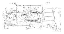
- FIG. 3A is a view of a reel feeder.
- FIG. 3B is another view of the reel feeder along the line 3 B in FIG. 3A .
- FIGS. 4A to 4E are different views of an example of a device used to improved reel feeder efficiency.
- FIGS. 5A to 5C are views of an example method of installing the device on the reel feeder.
- a feeder tape 10 includes cavities 14 that hold electronic components (e.g., an electronic component 16 ).
- the tape includes holes 22 configured to engage a tape feed sprocket (see, for example. a tape feed sprocket 50 in FIG. 3A ) on a reel feeder (e.g., a reel feeder 100 ( FIG. 3A )).
- the holes 22 are each spaced apart by a distance, D A , of about 4 mm.
- a distance, D E is associated with a pitch (also called a feeder pitch) such that the greater the distance D E , the greater the pitch.
- cover tape 18 is used to cover the electronic components 16 until they are ready to be picked (usually by pick-and-place machinery).
- the cover tape 18 is peeled away or retracted from a tape body 32 to expose the electronic components 16 in the cavities 14 .
- the cover tape 18 is retracted by the reel feeder.
- the cover tape 18 is adhered to the tape body 32 using adhesives.
- FIGS. 3A and 3B depicts the reel feeder 100 used to access the electronic components 14 on the feeder tape 10 by retracting the cover tape 18 .
- the reel feeder 100 includes a free link 102 , a take-up arm 104 , a take-up spring 106 and a take-up spool 108 .
- the free link 102 includes a slot 110 for which the take-up arm 104 is secured by a fastener 112 (e.g., a screw and bushing).
- the slot 110 has a length L s .
- the length of a gap 116 in the slot 110 between a first end 120 of the slot and the fastener 112 is a length L G .
- the width of the slot 110 is a width, W S .
- the reel feeder 100 is engaged by a pick-and-place machine (not shown).
- the pick-and-place machinery applies a force on the free link 102 in an upward direction 150 and the free link 102 is driven aftward allowing the take-up arm 104 to be pulled back by the take-up spring 106 .
- the take-up spring 106 acts on the take-up arm 104 to rotate the take-up spool 108 , which in turn puts tension on the cover tape 18 to retract it from the feeder tape 10 .
- the take-up arm 104 with the fastener 112 slips along the slot 110 towards the end 120 and the reel feeder 100 advances to the next electronic component 16 but fails to retract the cover tape 18 . Without removing the cover tape 18 , the pick-and-place machinery cannot access the covered electric components 16 resulting in lost electronic components, higher costs, and production delays.
- the slot 110 exists because the reel feeder 100 is required to accommodate a variety of feeder tape pitches, which means that the reel feeder 100 must provide flexibility relating to how far the take-up arm 104 travels when fired under the various different pitch settings.
- the take arm 104 is secured by fastener 112 and rides along the length of the slot 110 based on the pitch. This “slip joint” allows variability in the travel distance.
- a device 200 is used to prevent the movement of the take-up arm 104 along the slot 110 .
- the device 200 fills the slot 110 which results in the take-up arm 104 being driven directly by the free link 102 (in addition to the tension provided by the take-up spring 106 ).
- the free link 102 is directly driven by a pneumatic piston on the pick-and-place machinery and generates a force which is substantially greater than any forces developed by the take-up spring 106 . Having this direct drive on the take-up arm 104 virtually eliminates the failure mode resulting from inadequate retraction of the cover tape 18 .
- the fastener 112 and take-up arm 104 slide along the length of the slot 110 to accommodate the variable feeder pitch settings.
- the device 200 may be embodied in a variety of lengths in order to accommodate these various required pitch settings. Thus, which length of the device 200 the user will use will depend on the current pitch setting of the reel feeder 100 .
- the device 200 includes a first portion 210 and a second portion 220 .
- the first portion 210 has a length L D ( FIG. 4D ) which is less than or equal to the length L G of the gap 116 in the slot 110 .
- the first portion 210 includes a first end 230 that is concave shaped and configured to engage the fastener 112 .
- the first portion 210 also includes a second end 236 opposite the first end 230 that is configured to engage the second end 120 of the gap 116 .
- the first portion 210 also includes “snap-fit” retention tabs 250 used to hold device 200 after it is installed. For example, when the operator installs a device 200 onto a feeder 100 the walls of the free link 102 surrounding the gap 116 of the slot 110 exert a force on the retention tabs 250 which causes the retention tabs to flex as the device 200 enters the 110 slot. Once the device 200 is fully seated into slot 110 , then the retention tabs 200 are no longer under a load and spring back to their initial shape, allowing the retention tabs 250 to form an interference fit with the gap 116 of the slot 110 , thereby retaining the device 200 in place.
- the second portion 220 connected to the first portion 210 has a width W D ( FIG. 4C ) that is greater than the width W S of the slot 110 thereby adding structure that also can hold the device 210 secure in the gap 116 .
- the device 200 is configured to fill, or partially fill and to fit securely in the gap 116 .
- devices 200 are color schemed based on their length L D which corresponds to a pitch. For example, a device used for a 12 pitch setting is green while a 4 and 8 pitch setting has a device 200 that is red.
- the device 200 is installed and removed without the need for any tools or additional hardware.
- a user slides the device 200 into the gap 116 ( FIG. 5A ), presses down on the device 200 (e.g., using a thumb) ( FIG. 5B ) which results in the device 200 being secured in the gap 116 ( FIG. 5C ).
Landscapes
- Engineering & Computer Science (AREA)
- Manufacturing & Machinery (AREA)
- Microelectronics & Electronic Packaging (AREA)
- Physics & Mathematics (AREA)
- General Physics & Mathematics (AREA)
- Automation & Control Theory (AREA)
- Supply And Installment Of Electrical Components (AREA)
Abstract
Description
Claims (5)
Priority Applications (1)
| Application Number | Priority Date | Filing Date | Title |
|---|---|---|---|
| US14/527,900 US9513657B2 (en) | 2010-09-08 | 2014-10-30 | Method and apparatus to improve reel feeder efficiency |
Applications Claiming Priority (2)
| Application Number | Priority Date | Filing Date | Title |
|---|---|---|---|
| US12/877,501 US8893761B2 (en) | 2010-09-08 | 2010-09-08 | Method and apparatus to improve reel feeder efficiency |
| US14/527,900 US9513657B2 (en) | 2010-09-08 | 2014-10-30 | Method and apparatus to improve reel feeder efficiency |
Related Parent Applications (1)
| Application Number | Title | Priority Date | Filing Date |
|---|---|---|---|
| US12/877,501 Division US8893761B2 (en) | 2010-09-08 | 2010-09-08 | Method and apparatus to improve reel feeder efficiency |
Publications (2)
| Publication Number | Publication Date |
|---|---|
| US20150096163A1 US20150096163A1 (en) | 2015-04-09 |
| US9513657B2 true US9513657B2 (en) | 2016-12-06 |
Family
ID=44658820
Family Applications (2)
| Application Number | Title | Priority Date | Filing Date |
|---|---|---|---|
| US12/877,501 Active 2033-05-29 US8893761B2 (en) | 2010-09-08 | 2010-09-08 | Method and apparatus to improve reel feeder efficiency |
| US14/527,900 Active US9513657B2 (en) | 2010-09-08 | 2014-10-30 | Method and apparatus to improve reel feeder efficiency |
Family Applications Before (1)
| Application Number | Title | Priority Date | Filing Date |
|---|---|---|---|
| US12/877,501 Active 2033-05-29 US8893761B2 (en) | 2010-09-08 | 2010-09-08 | Method and apparatus to improve reel feeder efficiency |
Country Status (2)
| Country | Link |
|---|---|
| US (2) | US8893761B2 (en) |
| WO (1) | WO2012033589A1 (en) |
Families Citing this family (2)
| Publication number | Priority date | Publication date | Assignee | Title |
|---|---|---|---|---|
| US8893761B2 (en) * | 2010-09-08 | 2014-11-25 | Raytheon Company | Method and apparatus to improve reel feeder efficiency |
| EP2827692B1 (en) * | 2012-03-13 | 2018-07-18 | Fuji Machine Mfg. Co., Ltd. | Component mounting device feeder management system |
Citations (18)
| Publication number | Priority date | Publication date | Assignee | Title |
|---|---|---|---|---|
| US2831570A (en) | 1954-08-02 | 1958-04-22 | Sleeper & Hartley Inc | Wire coiling machine having cams for holding the feed rolls separated |
| JPH05132204A (en) | 1991-11-06 | 1993-05-28 | Mitsui Mining & Smelting Co Ltd | Reel setter |
| US5588614A (en) | 1994-07-07 | 1996-12-31 | Fuji Machine Mfg. Co., Ltd. | Electronic-component supplying cartridge |
| JP2000059097A (en) | 1998-08-04 | 2000-02-25 | Juki Corp | Device transfer equipment |
| US6513563B1 (en) | 1997-01-20 | 2003-02-04 | Matsushita Electric Industrial Co., Ltd. | Component feeding method and device |
| US20040200578A1 (en) * | 2003-04-10 | 2004-10-14 | Min Jin Ju | Tape feeder for chip mounters |
| US20070241028A1 (en) * | 2003-11-07 | 2007-10-18 | Mydata Automation Ab | Method and Device for Exposing Electronic Components |
| US20120055280A1 (en) * | 2010-09-08 | 2012-03-08 | Raytheon Company | Method and apparatus to improve reel feeder efficiency |
| US20130056156A1 (en) * | 2011-09-01 | 2013-03-07 | Raytheon Company | Method and apparatus to improve tape feeder handling |
| US20130284380A1 (en) * | 2012-04-27 | 2013-10-31 | Tsung-Chih Tsai | Feeder |
| US20140060749A1 (en) * | 2012-09-04 | 2014-03-06 | Samsung Techwin Co., Ltd. | Electronic component carrier tape feeding device and electronic component carrier tape feeding method |
| US20140150256A1 (en) * | 2011-08-25 | 2014-06-05 | Panasonic Corporation | Tape feeder, component mounting apparatus, and component mounting method |
| US20140318713A1 (en) * | 2013-03-15 | 2014-10-30 | Kelvin Wiley | Interchangeable cut tape / leaderless feeder finger adaptable to various surface mount assembly machine feeders for chip mounters |
| US20150181776A1 (en) * | 2012-05-29 | 2015-06-25 | Panasonic Intellectual Property Management Co., Ltd. | Attachment for feeder installation and method for feeder installation |
| US20150382523A1 (en) * | 2012-08-31 | 2015-12-31 | Young Soo Hwang | Apparatus For Automatically Supplying Carrier Tape Comprising Device for Automatically Exposing Parts |
| US20160192547A1 (en) * | 2013-08-26 | 2016-06-30 | Fuji Machine Mfg. Co., Ltd. | Component supply device |
| US20160185093A1 (en) * | 2013-08-26 | 2016-06-30 | Fuji Machine Mfg. Co., Ltd. | Feeder |
| US20160192548A1 (en) * | 2013-08-26 | 2016-06-30 | Fuji Machine Mfg. Co., Ltd. | Feeder |
-
2010
- 2010-09-08 US US12/877,501 patent/US8893761B2/en active Active
-
2011
- 2011-08-09 WO PCT/US2011/047043 patent/WO2012033589A1/en active Application Filing
-
2014
- 2014-10-30 US US14/527,900 patent/US9513657B2/en active Active
Patent Citations (21)
| Publication number | Priority date | Publication date | Assignee | Title |
|---|---|---|---|---|
| US2831570A (en) | 1954-08-02 | 1958-04-22 | Sleeper & Hartley Inc | Wire coiling machine having cams for holding the feed rolls separated |
| JPH05132204A (en) | 1991-11-06 | 1993-05-28 | Mitsui Mining & Smelting Co Ltd | Reel setter |
| US5588614A (en) | 1994-07-07 | 1996-12-31 | Fuji Machine Mfg. Co., Ltd. | Electronic-component supplying cartridge |
| US6513563B1 (en) | 1997-01-20 | 2003-02-04 | Matsushita Electric Industrial Co., Ltd. | Component feeding method and device |
| JP2000059097A (en) | 1998-08-04 | 2000-02-25 | Juki Corp | Device transfer equipment |
| US20040200578A1 (en) * | 2003-04-10 | 2004-10-14 | Min Jin Ju | Tape feeder for chip mounters |
| US20070241028A1 (en) * | 2003-11-07 | 2007-10-18 | Mydata Automation Ab | Method and Device for Exposing Electronic Components |
| US7713376B2 (en) * | 2003-11-07 | 2010-05-11 | Mydata Automation Ab | Method and device for exposing electronic components |
| US20150096163A1 (en) * | 2010-09-08 | 2015-04-09 | Raytheon Company | Method And Apparatus To Improve Reel Feeder Efficiency |
| US8893761B2 (en) * | 2010-09-08 | 2014-11-25 | Raytheon Company | Method and apparatus to improve reel feeder efficiency |
| US20120055280A1 (en) * | 2010-09-08 | 2012-03-08 | Raytheon Company | Method and apparatus to improve reel feeder efficiency |
| US20140150256A1 (en) * | 2011-08-25 | 2014-06-05 | Panasonic Corporation | Tape feeder, component mounting apparatus, and component mounting method |
| US20130056156A1 (en) * | 2011-09-01 | 2013-03-07 | Raytheon Company | Method and apparatus to improve tape feeder handling |
| US20130284380A1 (en) * | 2012-04-27 | 2013-10-31 | Tsung-Chih Tsai | Feeder |
| US20150181776A1 (en) * | 2012-05-29 | 2015-06-25 | Panasonic Intellectual Property Management Co., Ltd. | Attachment for feeder installation and method for feeder installation |
| US20150382523A1 (en) * | 2012-08-31 | 2015-12-31 | Young Soo Hwang | Apparatus For Automatically Supplying Carrier Tape Comprising Device for Automatically Exposing Parts |
| US20140060749A1 (en) * | 2012-09-04 | 2014-03-06 | Samsung Techwin Co., Ltd. | Electronic component carrier tape feeding device and electronic component carrier tape feeding method |
| US20140318713A1 (en) * | 2013-03-15 | 2014-10-30 | Kelvin Wiley | Interchangeable cut tape / leaderless feeder finger adaptable to various surface mount assembly machine feeders for chip mounters |
| US20160192547A1 (en) * | 2013-08-26 | 2016-06-30 | Fuji Machine Mfg. Co., Ltd. | Component supply device |
| US20160185093A1 (en) * | 2013-08-26 | 2016-06-30 | Fuji Machine Mfg. Co., Ltd. | Feeder |
| US20160192548A1 (en) * | 2013-08-26 | 2016-06-30 | Fuji Machine Mfg. Co., Ltd. | Feeder |
Non-Patent Citations (4)
| Title |
|---|
| PCT International Preliminary Report on Patentability for PCT/US2011/047043 dated Mar. 21, 2013, 6 Pages. |
| PCT Search Report of the International Searching Authority for PCT-US2011/047043 dated Nov. 14, 2011, 4 Pages. |
| PCT Written Opinion of the International Searching Authority for PCT/US2011/047043 dated Nov. 14, 2011, 5 Pages. |
| U.S. Appl. No. 12/877,501, filed Sep. 8, 2010. |
Also Published As
| Publication number | Publication date |
|---|---|
| US8893761B2 (en) | 2014-11-25 |
| US20120055280A1 (en) | 2012-03-08 |
| WO2012033589A1 (en) | 2012-03-15 |
| US20150096163A1 (en) | 2015-04-09 |
Similar Documents
| Publication | Publication Date | Title |
|---|---|---|
| JP4370058B2 (en) | Equipment for mounting components on a board | |
| EP3041337B1 (en) | Component mounting device | |
| WO2016117091A1 (en) | Feeder device | |
| JPH0250640B2 (en) | ||
| US20100239401A1 (en) | Carrier tape feeder for chip mounter | |
| US9513657B2 (en) | Method and apparatus to improve reel feeder efficiency | |
| US5598986A (en) | Component supply apparatus | |
| CN105144863B (en) | Automatic carrier band device for feeding | |
| CN106660710A (en) | Component supply device | |
| KR102051987B1 (en) | Connection jig tape | |
| JP2004323028A (en) | Cover for carrier tape and method of mounting it | |
| KR101133789B1 (en) | Carrier tape guide of tape feeder for chip mounter | |
| JPS60113998A (en) | Electronic part assembly | |
| JP4544428B2 (en) | Tape extension device and tape extension method | |
| JP6956431B2 (en) | Feeder device | |
| JP2005093670A (en) | Tape feeder | |
| KR200271836Y1 (en) | A semiconductor chip be loaded tape connection body and it's connection device | |
| US20070031626A1 (en) | Connecting splice for connecting reel | |
| JP3840968B2 (en) | Tape feeder | |
| JPH0343367A (en) | Part collecting body | |
| JP3089088U (en) | Tape cover | |
| KR100347374B1 (en) | Mounting Structure for Vinyl Recovering Reel in Tape Feeder | |
| JP2005175046A (en) | Tape feeder | |
| KR20200107258A (en) | A Feeder for a Carrier Tape | |
| JP2020155791A (en) | Component supply device |
Legal Events
| Date | Code | Title | Description |
|---|---|---|---|
| AS | Assignment |
Owner name: RAYTHEON COMPANY, MASSACHUSETTS Free format text: ASSIGNMENT OF ASSIGNORS INTEREST;ASSIGNORS:TAYLOR, W. ROYCE, IV;KOLLER, RYAN J.;REEL/FRAME:034257/0626 Effective date: 20141121 |
|
| STCF | Information on status: patent grant |
Free format text: PATENTED CASE |
|
| MAFP | Maintenance fee payment |
Free format text: PAYMENT OF MAINTENANCE FEE, 4TH YEAR, LARGE ENTITY (ORIGINAL EVENT CODE: M1551); ENTITY STATUS OF PATENT OWNER: LARGE ENTITY Year of fee payment: 4 |
|
| MAFP | Maintenance fee payment |
Free format text: PAYMENT OF MAINTENANCE FEE, 8TH YEAR, LARGE ENTITY (ORIGINAL EVENT CODE: M1552); ENTITY STATUS OF PATENT OWNER: LARGE ENTITY Year of fee payment: 8 |