US9513271B2 - Moisture measuring apparatus and computer-readable medium - Google Patents
Moisture measuring apparatus and computer-readable medium Download PDFInfo
- Publication number
- US9513271B2 US9513271B2 US13/928,184 US201313928184A US9513271B2 US 9513271 B2 US9513271 B2 US 9513271B2 US 201313928184 A US201313928184 A US 201313928184A US 9513271 B2 US9513271 B2 US 9513271B2
- Authority
- US
- United States
- Prior art keywords
- moisture
- soil
- measuring apparatus
- state
- sensor
- Prior art date
- Legal status (The legal status is an assumption and is not a legal conclusion. Google has not performed a legal analysis and makes no representation as to the accuracy of the status listed.)
- Active, expires
Links
- 239000002689 soil Substances 0.000 claims abstract description 123
- 238000005259 measurement Methods 0.000 claims abstract description 46
- 230000006870 function Effects 0.000 claims description 5
- 238000009529 body temperature measurement Methods 0.000 claims 2
- 241000196324 Embryophyta Species 0.000 description 12
- 238000010586 diagram Methods 0.000 description 12
- 238000004891 communication Methods 0.000 description 4
- 230000008020 evaporation Effects 0.000 description 4
- 238000001704 evaporation Methods 0.000 description 4
- 101100298225 Caenorhabditis elegans pot-2 gene Proteins 0.000 description 3
- 238000000034 method Methods 0.000 description 3
- 239000002245 particle Substances 0.000 description 3
- 239000004576 sand Substances 0.000 description 3
- XLYOFNOQVPJJNP-UHFFFAOYSA-N water Substances O XLYOFNOQVPJJNP-UHFFFAOYSA-N 0.000 description 3
- 230000005540 biological transmission Effects 0.000 description 2
- 230000008595 infiltration Effects 0.000 description 2
- 238000001764 infiltration Methods 0.000 description 2
- RYGMFSIKBFXOCR-UHFFFAOYSA-N Copper Chemical compound [Cu] RYGMFSIKBFXOCR-UHFFFAOYSA-N 0.000 description 1
- 241000218922 Magnoliophyta Species 0.000 description 1
- 230000004397 blinking Effects 0.000 description 1
- 230000001413 cellular effect Effects 0.000 description 1
- 229910052802 copper Inorganic materials 0.000 description 1
- 239000010949 copper Substances 0.000 description 1
- 238000005516 engineering process Methods 0.000 description 1
- 210000003811 finger Anatomy 0.000 description 1
- 238000010413 gardening Methods 0.000 description 1
- 239000000463 material Substances 0.000 description 1
- 235000019362 perlite Nutrition 0.000 description 1
- 239000010451 perlite Substances 0.000 description 1
- 210000003813 thumb Anatomy 0.000 description 1
Images


Classifications
-
- G—PHYSICS
- G01—MEASURING; TESTING
- G01N—INVESTIGATING OR ANALYSING MATERIALS BY DETERMINING THEIR CHEMICAL OR PHYSICAL PROPERTIES
- G01N33/00—Investigating or analysing materials by specific methods not covered by groups G01N1/00 - G01N31/00
- G01N33/24—Earth materials
- G01N33/246—Earth materials for water content
-
- G—PHYSICS
- G01—MEASURING; TESTING
- G01N—INVESTIGATING OR ANALYSING MATERIALS BY DETERMINING THEIR CHEMICAL OR PHYSICAL PROPERTIES
- G01N27/00—Investigating or analysing materials by the use of electric, electrochemical, or magnetic means
- G01N27/02—Investigating or analysing materials by the use of electric, electrochemical, or magnetic means by investigating impedance
- G01N27/04—Investigating or analysing materials by the use of electric, electrochemical, or magnetic means by investigating impedance by investigating resistance
- G01N27/048—Investigating or analysing materials by the use of electric, electrochemical, or magnetic means by investigating impedance by investigating resistance for determining moisture content of the material
Definitions
- the present invention relates to a moisture measuring apparatus and a computer-readable medium for measuring a state of moisture in a measurement target object such as soil.
- soil moisture measuring apparatuses developed for farm work or kitchen gardens measure moisture included in soil based on, for example, an electric resistance method.
- a measuring apparatus having a simplified configuration in which two measuring electrodes are provided on the external surface of the body of the apparatus, as a soil moisture measuring apparatus which is thrust into soil for use and has been developed for the nurturing assistance of foliage plants and the like (See Japanese Patent No. 2608679).
- the soil moisture measuring apparatus having a simplified configuration
- the whole of the two measuring electrodes provided on the external surface of the body of the apparatus is brought into contact with soil.
- the measuring apparatus is thrust into soil, or its position is transferred, there occurs a gap between the soil and the measuring apparatus. Accordingly, there is a problem in that the gap causes a substantial reduction in a contact area between the measuring apparatus and the soil, which impedes exact measurements.
- An object of the present invention is to provide a moisture measuring apparatus which can provide a user with a mounting state as to whether the moisture measuring apparatus has been appropriately mounted, when the body of the apparatus for measuring a state of moisture in a measurement target object is mounted into the measurement target object.
- a moisture measuring apparatus comprising: a moisture measuring section which measures a state of moisture in a measurement target object; a determination section which determines a mounting state of the moisture measuring apparatus in the measurement target object based on the state of moisture measured by the moisture measuring section; and an informing section which informs a result of determination by the determination section.
- the mounting state as to whether the moisture measuring apparatus has been appropriately mounted can be provided for the user, whereby the exact measurement can be expected.
- FIGS. 1A and 1B are diagrams to describe a moisture measuring apparatus which measures the amount of moisture in soil (measurement target object), as a measuring apparatus which measures the nurturing environment of plants.
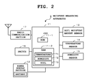
- FIG. 2 is a block diagram illustrating basic components of the moisture measuring apparatus 1 .
- FIGS. 3A to 3C are diagrams to describe a temperature table T 1 , a humidity table T 2 , and a soil table T 3 in a RAM 11 - 2 .
- FIG. 4 is a diagram illustrating a state of change in a moisture amount decrease ratio in a case where there is no gap between a sensor electrode 1 a and soil immediately after the start of watering, and in a case where there is a gap between the sensor electrode 1 a and the soil immediately after the start of watering.
- FIG. 5 is a flowchart outlining the operation of a characteristic portion of the embodiment from among all of the operations of the moisture measuring apparatus 1 .
- FIG. 6 is a flowchart to describe in detail processing (Step A 4 in FIG. 5 ) for determining a judgment threshold value and a judgment time which are used to judge the presence or absence of a gap, based on the present nurturing environment.
- FIG. 1 is a diagram to describe a moisture measuring apparatus which measures the amount of moisture in soil (measurement target object), as a measuring apparatus which measures the nurturing environment of plants.
- the moisture measuring apparatus 1 is a plant nurturing environment measuring apparatus of a simplified configuration in which the nurturing environment (state of moisture in soil) of plants such as planted trees and flowering plants is measured based on an electric resistance method.
- the entire case thereof (body of apparatus) is made up of a long and narrow hollow rod body having a tapered shape. As illustrated in FIG.
- the rod body is structured to be buried into soil in a such a manner that the lower side portion of the case thereof that is, approximately a lower half on the side of the tip end portion is thrust into the soil (measurement target object) illustrated by the reference numeral 2 .
- two plate-shaped sensor electrodes 1 a which are made of materials such as copper are arranged separately from each other on the surface on the lower portion side of the case (body of apparatus).
- the moisture measuring apparatus 1 measures the amount of moisture in soil (measurement target object) based on an electric resistance value between the two sensor electrodes 1 a .
- reference numeral L represents a range where the moisture measuring apparatus 1 is buried into the soil.
- a user thrusts the moisture measuring apparatus 1 into the soil in such a manner that the two sensor electrodes 1 a are completely buried thereinto.
- an arc-shaped handle 1 b is projectingly formed (integrally molded) on the upper end one-side portion of the case.
- the moisture measuring apparatus 1 transmits and receives measurement data (sensor data) between an information collection terminal 3 and the moisture measuring apparatus 1 based on general-purpose communication such as wireless LAN (Local Area Network).
- the information collection terminal 3 is, for example, a multifunctional portable cellular phone apparatus, which is referred to as a PC (personal computer) or a smart phone owned by the user.
- the take-out or put-in can smoothly be carried out by pressing the upper end surface of the moisture measuring apparatus 1 with the thick of the thumb while hooking the index finger on the lower side of the handle 1 b.
- FIG. 2 is a block diagram illustrating basic components of the moisture measuring apparatus 1 .
- a CPU 11 in FIG. 2 which is operated based on the power supplied from a power supply section 12 , includes a ROM 11 - 1 which stores the control program and a RAM 11 - 2 which can store measurement data (sensor data) and the like.
- the CPU 11 is a central processing unit which controls the entire operations of the moisture measuring apparatus 1 in accordance with the program.
- a temperature table T 1 , a humidity table T 2 , and a soil table T 3 which are described later, are stored in the RAM 11 - 2 .
- the power supply section 12 includes a power battery and is a power source control circuit which converts the output of the battery into prescribed voltage and supplies the voltage to each section.
- the moisture measuring apparatus 1 includes a temperature sensor 14 which measures an outside air temperature as plant nurturing environment, and a humidity sensor 15 which measures outside air humidity as plant nurturing environment, in addition to a soil moisture amount sensor 13 which measures the amount of moisture (humidity) in the soil in the flower pot 2 , as various sensors to measure plant nurturing environment.
- the soil moisture amount sensor 13 is a sensor to measure the amount of moisture as a state of moisture in soil based on the electric resistance value between the two sensor electrodes 1 a described above.
- the CPU 11 judges the mounting state of the moisture measuring apparatus 1 in soil (whether or not the current state is a state where a gap has been occurred between the sensor electrode 1 a and soil) based on change in the moisture state (moisture amount) measured by the soil moisture amount sensor 13 in a predetermined amount of time.
- a switch section 16 is a key operation section which includes a power on/off key and the like.
- a radio communication section 17 is a communication section which carries out general-purpose protocol communication between the moisture measuring apparatus 1 and the information collection terminal 3 with the use of the wireless LAN (WLAN) and standard Internet protocol (TCP/IP).
- FIG. 3 is a diagram to describe the temperature table T 1 , the humidity table T 2 , and the soil table T 3 in the RAM 11 - 2 .
- the temperature table T 1 , the humidity table T 2 , and the soil table T 3 are tables that are used when the CPU 11 judges the mounting state of the moisture measuring apparatus 1 in soil (whether or not the current state is a state where a gap has been occurred between the sensor electrode 1 a and soil). That is, the contact area between the sensor electrode 1 a and soil is substantially reduced when there is a gap between the sensor electrode 1 a and soil, which impedes exact measurements. Accordingly, in the embodiment of the present invention, the CPU 11 judges the mounting state of the moisture measuring apparatus 1 . At the time of this judgment, the CPU 11 refers to the contents of the aforementioned temperature table T 1 , the humidity table T 2 , and the soil table T 3 .
- FIG. 4 is a diagram illustrating a state of change in a moisture amount decrease ratio in a case where there is no gap between the sensor electrode 1 a and soil immediately after the start of watering, and in a case where there is a gap between the sensor electrode 1 a and the soil immediately after the start of watering.
- the horizontal axis represents time (unit, second), and the vertical axis represents the moisture amount decrease ratio.
- the curve in a dotted line represents the change curve of the moisture amount in the case there is no gap between the sensor electrode 1 a and the soil.
- the curve in a solid line represents the change curve of the moisture amount in the case there is a gap between the sensor electrode 1 a and the soil.
- the gap between the sensor electrode 1 a and the soil is filled with water immediately after the start of watering to the soil, whereby the sensor electrode 1 a is brought into contact with the water.
- the water is infiltrated into the soil from the gap, and there occurs the gap between the sensor electrode 1 a and the soil again, so that the moisture amount decrease ratio is rapidly changed, as illustrated by the curve in the solid line in the diagram.
- the moisture amount decrease ratio reaches approximately “1 to 0.1”, which is the reduction of approximately 90%.
- the CPU 11 judges the presence or absence of a gap based on a moisture amount decrease ratio. That is, the CPU 11 acquires a moisture amount decrease ratio (a ratio of the maximum value to the minimum value) based on a moisture amount (maximum value) immediately after the start of watering and a moisture amount (minimum value) after a predetermined amount of time (60 seconds) from the start of watering. Then, the CPU 11 judges whether or not there is a gap between the sensor electrode 1 a and the soil by comparing the moisture amount decrease ratio with a predetermined threshold value.
- a moisture amount decrease ratio a ratio of the maximum value to the minimum value
- a moisture amount decrease ratio after a predetermined amount of time is 25%, whose reduction level serves as a judgment threshold value.
- the CPU 11 judges that there is a gap between the sensor electrode 1 a and the soil.
- the CPU 11 judges that there is no gap between the sensor electrode 1 a and the soil.
- the time and the threshold value that are used in this judgment are affected by the present nurturing environment (temperature, humidity, and soil classification). Accordingly, the CPU 11 determines a judgment threshold value and a judgment time suitable for the present nurturing environment, with reference to the temperature table T 1 , the humidity table T 2 , and the soil table T 3 .
- the temperature table T 1 is configured to store “judgment threshold value” and “judgment time” corresponding to “temperature”.
- the amount of moisture evaporation is affected by temperatures, so that “low setting”, “standard value (ideal value: for example, 25% reduction)”, and “high setting” for “judgment threshold value”, and “short setting”, “standard value (ideal value: for example, 60 seconds)”, and “long setting” for “judgment time” are stored corresponding to “TH (high)”, “Tth (ideal temperature range for example, 10 to 25 degrees)”, and “TL (low)” for “temperatures”.
- the humidity table T 2 is configured to store “judgment threshold value” and “judgment time” corresponding to “humidity”.
- the amount of moisture evaporation is affected by humidity, so that “high setting”, “standard value (ideal value: for example, 25% reduction)”, and “low setting” for “judgment threshold value”, and “long setting”, “standard value (ideal value a for example, 60 seconds)”, and “short setting” for “judgment time” are stored corresponding to “TH (high)”, “Tth (ideal humidity range: for example, 45% to 60%)”, and “TL (low)” for “humidity”.
- the soil table T 3 is configured to store “judgment threshold value” and “judgment time” corresponding to “soil classification”.
- the influence with respect to soil classification is attributed to the magnitude of particles of earth (drainage and infiltration), and the magnitude of particles is expressed in an inequality of “black soil” ⁇ “sand” ⁇ “earth for foliage plants”, so that “standard value (ideal value: for example, 25% reduction)”, “low setting”, and “much more lower setting” for “judgment threshold value”, and “standard value (ideal values for example, 60 seconds)”, “short setting”, and “much more shorter setting” for “judgment time” are stored corresponding to “black soil” “sand”, and “earth for foliage plants” for “soil classification”.
- each function described in the flowcharts is stored in a readable program code format, and operations based on these program codes are sequentially performed. Also, operations based on the above-described program codes transmitted over a transmission medium such as a network can also be sequentially performed. That is, the unique operations of the present embodiment can be performed using programs and data supplied from an outside source over a transmission medium, in addition to a recording medium.
- FIG. 5 is a flowchart outlining the operation of a characteristic portion of the embodiment from among all of the operations of the moisture measuring apparatus 1 , which is started upon power-on.
- the moisture measuring apparatus 1 is thrust into soil which is a measurement target object.
- the CPU 11 acquires data regarding the amount of moisture in the soil, which is measured based on an electric resistance value between the two sensor electrodes 1 a by the soil moisture amount sensor 13 (Step A 1 ). Subsequently, the CPU 11 judges whether it is immediately after the start of watering based on the magnitude of the value of the moisture amount data (Step A 2 ).
- the CPU 11 judges whether the value of the measured moisture amount data is equal to or higher than a predetermined threshold value.
- the CPU 11 compares the previous measurement result with the present measurement result and judges whether it is immediately after the start of watering, based on whether the moisture amount has rapidly increased.
- the method of the judgment may be arbitrarily determined.
- the CPU 11 when judged that it is not immediately after the start of watering (Step A 2 , NO), the CPU 11 allows the RAN 11 - 2 to store the moisture amount data measured by the soil moisture amount sensor 13 as other processing, or carries out processing for transmitting the moisture amount data in the RAM 11 - 2 to the information collection terminal 3 in response to an access request from the information collection terminal 3 (Step A 3 ). Then, the CPU 11 returns to the aforementioned Step A 1 where data regarding the amount of moisture in the soil is acquired.
- the CPU 11 carries out processing for determining a judgment threshold value and a judgment time which are used to judge the presence or absence of a gap, based on the present nurturing environment (Step A 4 ).
- FIG. 6 is a flowchart to describe in detail the processing (Step A 4 in FIG. 5 ) for determining a judgment threshold value and a judgment time which are used to judge the presence or absence of a gap, based on the present nurturing environment.
- the CPU 11 acquires temperature data measured based on the temperature table T 1 (Step B 1 ).
- the CPU 11 refers to the temperature table T 1 based on the temperature data, and determines a judgment threshold value and a judgment time corresponding to the present nurturing environment (temperature) by comparing the present nurturing environment (temperature) with the temperature of the ideal value (standard value) (Step B 2 ).
- the CPU 11 determines “standard value (ideal value: for example, 25% reduction)” as “judgment threshold value” and determines “standard value (ideal value; for example, 60 seconds)” as “judgment time” Also, when the present nurturing environment is higher than the ideal value (standard value) the CPU 11 determines “low setting” as “judgment threshold value” and determines “short setting” as “judgment time”. When the present nurturing environment is lower than the ideal value (standard value), the CPU 11 determines “high setting” as “judgment threshold value” and determines “long setting” as “judgment time”.
- the CPU 11 acquires humidity data measured based on the humidity table T 2 (Step B 3 ). Subsequently, the CPU 11 refers to the humidity table T 2 based on the humidity data, and determines a judgment threshold value and a judgment time corresponding to the present nurturing environment (humidity) by comparing the present nurturing environment (humidity) with the humidity of the ideal value (standard value) (Step B 4 ). That is, when the present nurturing environment (humidity) is equivalent to the ideal value (standard value), the CPU 11 determines “standard value (ideal value: for example, 25% reduction)” as “judgment threshold value” and determines “standard value (ideal value: for example, 60 seconds)” as “judgment time”.
- the CPU 11 determines “high setting” as “judgment threshold value” and determines “long setting” as “judgment time”.
- the CPU 11 determines “low setting” as “judgment threshold value” and determines “short setting” as “judgment time”.
- the CPU 11 acquires the classification data of the soil (Step B 5 ).
- the CPU 11 reads out and acquires the data.
- the CPU 11 acquires the classification data of the soil inputted based on a user operation.
- the CPU 11 refers to the soil table T 3 based on the acquired classification data of the soil, and determines a judgment threshold value and a judgment time corresponding to the present nurturing environment (soil classification) by comparing the present nurturing environment (soil classification) with the soil of the ideal value (standard value) (Step B 6 ).
- the CPU 11 determines “standard value (ideal value: for example, 25% reduction)” as “judgment threshold value” and determines “standard value (ideal value for example, 60 seconds)” as “judgment time”. Also, when the soil classification is sand, the CPU 11 determines “low setting” as “judgment threshold value” and determines “short setting” as “judgment time”. When the soil classification is the earth for foliage plants, the CPU 11 determines “much more lower setting” as “judgment threshold value” and determines “much more shorter setting” as “judgment time”.
- the CPU 11 calculates the decrease ratio of the moisture amount corresponding to change in the moisture amount occurred in a time period between the start of the watering and the end of the judgment time (Step A 5 ). In this case, the CPU 11 calculates the moisture amount decrease ratio (a ratio of the maximum value to the minimum value) based on the measurement value (maximum value) measured by the soil moisture amount sensor 13 immediately after the start of the watering and the measurement value (minimum value) measured by the soil moisture amount sensor 13 after the elapse of the judgment time.
- the CPU 11 judges whether or not the calculated ratio is higher than the judgment threshold value by comparing the calculated moisture amount decrease ratio with the judgment threshold value. Then, the CPU 11 determines the mounting state of the moisture measuring apparatus 1 in the soil based on the result (judges whether or not the current state is a state where a gap has been occurred between the sensor electrode 1 a and the soil) (Step A 6 ).
- Step A 6 when the moisture amount decrease ratio measured this time is equal to or lower than the judgment threshold value (Step A 6 , NO), the CPU 11 judges that the current state is a normal state where no gap has been occurred between the sensor electrode 1 a and the soil, and returns to the aforementioned Step A 1 where data regarding the amount of moisture in the soil is acquired.
- the CPU 11 judges that the current state is an unusual state where a gap has been occurred between the sensor electrode 1 a and the soil, and proceeds to the next Step A 7 a .
- Step A 7 the CPU 11 transmits to the information collection terminal 3 a request to re-insert the moisture measuring apparatus 1 as a warning message (Step A 7 ). Then, the CPU 11 returns to the aforementioned Step A 1 where data regarding the amount of moisture in the soil is acquired.
- the moisture measuring apparatus 1 makes a judgment regarding the mounting state of the moisture measuring apparatus 1 in soil (measurement target object) based on the moisture state measured by the soil moisture amount sensor 13 , and informs the judgment result.
- the mounting state as to whether the moisture measuring apparatus 1 has been appropriately mounted can be provided to the user, whereby the exact measurement can be expected.
- the moisture measuring apparatus 1 acquires change in a moisture state in a predetermined time period based on a result of measurement by the soil moisture amount sensor 13 , and thereby judges the mounting state of the moisture measuring apparatus 1 in the soil. As a result of this configuration, more exact judgment can be made, compared with a case where a mounting state is judged based only on a moisture amount measured at certain timing.
- the moisture measuring apparatus 1 makes a judgment regarding the mounting state of the moisture measuring apparatus 1 based on whether the ratio of the maximum value to the minimum value (moisture amount decrease ratio) in change in a moisture state in a predetermined time period measured by the soil moisture amount sensor 13 is equal to or higher than a predetermined threshold value.
- the moisture measuring apparatus 1 judges whether the current state is a mounting state where a gap has been occurred between the sensor electrode 1 a and the soil.
- the moisture measuring apparatus 1 judges whether it is immediately after the start of watering to soil based on the state of moisture in the soil, and makes a judgment regarding the mounting state based on whether or not change in the moisture state measured in a predetermined time period immediately after the start of the watering (the ratio of the maximum value to the minimum value) is equal to or higher than a predetermined threshold value.
- the mounting state can be judged based on a moisture state which substantially changes from when watering is started until when a predetermined amount of time elapses, whereby the judgment can be made more steadily and readily.
- the moisture measuring apparatus 1 refers to the temperature table T 1 based on temperature measured by the temperature sensor 14 and makes a judgment regarding the mounting state based on a judgment standard corresponding to the temperature.
- the judgment standard can be changed corresponding to temperature that affects the amount of moisture evaporation, which makes it possible to respond to change in a measurement environment (temperature) and provide more steady judgment.
- the moisture measuring apparatus 1 refers to the humidity table T 2 based on humidity measured by the humidity sensor 15 and makes a judgment regarding the mounting state based on a judgment standard corresponding to the humidity.
- the judgment standard can be changed corresponding to humidity which affects the amount of moisture evaporation, which makes it possible to respond to change in a measurement environment (humidity) and provide more steady judgment.
- the moisture measuring apparatus 1 refers to the soil table T 3 based on soil classification serving as a measurement environment, and judges the mounting state based on a judgment standard corresponding to the soil classification.
- the judgment standard can be changed corresponding to soil classification which affects the magnitude of particles of soil (drainage and infiltration), which makes it possible to respond to change in a measurement environment (soil classification) and provide more steady judgment.
- the mounting state of the moisture measuring apparatus 1 is transmitted to the information collection terminal 3 , so that, even when the user is away from the moisture measuring apparatus 1 , he or she can check the mounting state of the moisture measuring apparatus 1 , and can immediately respond to the situation of the moisture measuring apparatus 1 .
- the mounting state of the moisture measuring apparatus 1 is transmitted to the information collection terminal 3 .
- a notification sound section which emits an alarm sound or a display section which displays a blinking display and messages may be provided for the moisture measuring apparatus 1 . In this case, if it is immediately after the start of watering, the user is near the moisture measuring apparatus 1 and therefore the mounting state of the moisture measuring apparatus 1 can be informed to the user.
- soil has been exemplified as the measurement target object.
- perlite for gardening and other water retention members may be applied in place of the soil.
- the amount of moisture has been exemplified as the state of moisture in soil.
- the moisture content ratio may be applied.
- the mounting state of the moisture measuring apparatus 1 is judged based on a result of measurement by the soil moisture amount sensor 13 .
- the mounting state may be judged based on a combination of a result of measurement by the soil moisture amount sensor 13 and a result of measurement by another sensor (for example, a pressure sensor).
- the determination of a judgment threshold value and a judgment time regarding a gap is made based on temperature data, humidity data, and soil classification data.
- the determination may be made based only on one of temperature data, humidity data, and soil classification data or a combination of the two out of these pieces of data.
- the determination of a judgment threshold value and a judgment time regarding a gap may be made based on data other than the aforementioned three pieces of data.
- the “devices” or the “sections” described in the above-described embodiment are not required to be in a single housing and may be separated into a plurality of housings by function.
- the steps in the above-described flowcharts are not required to be processed in time-series, and may be processed in parallel, or individually and independently.
Landscapes
- Life Sciences & Earth Sciences (AREA)
- Chemical & Material Sciences (AREA)
- Health & Medical Sciences (AREA)
- Engineering & Computer Science (AREA)
- Immunology (AREA)
- General Physics & Mathematics (AREA)
- Pathology (AREA)
- General Health & Medical Sciences (AREA)
- Biochemistry (AREA)
- Analytical Chemistry (AREA)
- Physics & Mathematics (AREA)
- Medicinal Chemistry (AREA)
- Food Science & Technology (AREA)
- General Life Sciences & Earth Sciences (AREA)
- Remote Sensing (AREA)
- Environmental & Geological Engineering (AREA)
- Geology (AREA)
- Chemical Kinetics & Catalysis (AREA)
- Electrochemistry (AREA)
- Investigating Or Analyzing Materials By The Use Of Electric Means (AREA)
Applications Claiming Priority (2)
| Application Number | Priority Date | Filing Date | Title |
|---|---|---|---|
| JP2012-161409 | 2012-07-20 | ||
| JP2012161409A JP6057119B2 (ja) | 2012-07-20 | 2012-07-20 | 水分測定装置及びプログラム |
Publications (2)
| Publication Number | Publication Date |
|---|---|
| US20140025300A1 US20140025300A1 (en) | 2014-01-23 |
| US9513271B2 true US9513271B2 (en) | 2016-12-06 |
Family
ID=49947256
Family Applications (1)
| Application Number | Title | Priority Date | Filing Date |
|---|---|---|---|
| US13/928,184 Active 2035-08-17 US9513271B2 (en) | 2012-07-20 | 2013-06-26 | Moisture measuring apparatus and computer-readable medium |
Country Status (3)
| Country | Link |
|---|---|
| US (1) | US9513271B2 (enExample) |
| JP (1) | JP6057119B2 (enExample) |
| CN (1) | CN103575768B (enExample) |
Cited By (2)
| Publication number | Priority date | Publication date | Assignee | Title |
|---|---|---|---|---|
| US20170193796A1 (en) * | 2016-01-06 | 2017-07-06 | Fanuc Corporation | Machine tool having function of monitoring sealing of control panel |
| WO2019077417A1 (en) * | 2017-10-16 | 2019-04-25 | King Abdullah University Of Science And Technology | SENSOR SYSTEM, PRODUCTION METHOD, AND SENSOR DEPLOYMENT SYSTEM |
Families Citing this family (8)
| Publication number | Priority date | Publication date | Assignee | Title |
|---|---|---|---|---|
| CN104792969B (zh) * | 2015-04-22 | 2016-08-31 | 三峡大学 | 一种基于温湿度传感器的土壤吸力值现场无线测量系统 |
| CN208621550U (zh) * | 2016-12-12 | 2019-03-19 | 株式会社村田制作所 | 水分传感器以及使用了该水分传感器的种植田管理系统 |
| EP3680656A4 (en) * | 2017-09-08 | 2021-11-10 | Cabinotier Co., Ltd. | SOIL HUMIDITY INDICATOR, WATER DETECTION UNIT USED IN SOIL HUMIDITY INDICATOR, BODY HOUSING, WATER DETECTION UNIT MANUFACTURING PROCESS AND HUMIDITY INDICATOR MANUFACTURING METHOD GROUND |
| US12306129B2 (en) | 2020-08-20 | 2025-05-20 | Univerzita Pardubice | System for measuring temperature and moisture of air and soil with wireless data transmission and method of its production |
| KR102350571B1 (ko) * | 2021-01-21 | 2022-01-11 | 정승백 | 화분 배양토의 함수율 측정장치 |
| CN113057041B (zh) * | 2021-02-23 | 2022-07-19 | 中国地质大学(武汉) | 可视化植物种植系统及方法 |
| JP7538746B2 (ja) * | 2021-03-05 | 2024-08-22 | 鹿島建設株式会社 | 土質測定装置及び土質測定方法 |
| US20240151671A1 (en) * | 2022-11-05 | 2024-05-09 | Devon Mark Cioffi | Soil-powered LED Plant Moisture Meter |
Citations (4)
| Publication number | Priority date | Publication date | Assignee | Title |
|---|---|---|---|---|
| JPH04134060U (ja) | 1991-06-04 | 1992-12-14 | 光子 小栗 | 水分検知器 |
| JPH07190974A (ja) | 1993-12-27 | 1995-07-28 | Teruaki Ito | 植物成育用土壌の水分含有度監視装置 |
| JP2003265056A (ja) | 2002-03-19 | 2003-09-24 | Aichi Prefecture | 土壌水分量検出方法、鉢植え栽培の給水制御方法及び給水制御システム |
| US7183779B2 (en) * | 2004-12-28 | 2007-02-27 | Spectrum Technologies, Inc. | Soil probe device and method of making same |
Family Cites Families (7)
| Publication number | Priority date | Publication date | Assignee | Title |
|---|---|---|---|---|
| JPS59148856A (ja) * | 1983-02-14 | 1984-08-25 | Iseki & Co Ltd | 含水率測定装置における異常検出装置 |
| US5260666A (en) * | 1991-09-23 | 1993-11-09 | Troxler Electronic Laboratories, Inc. | Capacitance monitor for soil moisture |
| CN2354128Y (zh) * | 1998-12-29 | 1999-12-15 | 中国科学院水利部水土保持研究所 | 土壤渗透测定装置 |
| JP2001215203A (ja) * | 2000-02-01 | 2001-08-10 | Kawasaki Kiko Co Ltd | 電気伝導度測定装置、土壌導電率測定方法及び土壌溶液導電率測定装置 |
| CN200979529Y (zh) * | 2006-11-14 | 2007-11-21 | 西北农林科技大学 | 一种基于红外辐射的土壤水分测量仪 |
| CN101281183B (zh) * | 2008-06-03 | 2012-11-07 | 华南农业大学 | 一种稻田水分传感器 |
| CN101598690B (zh) * | 2009-07-09 | 2011-05-11 | 北京师范大学 | 基于热脉冲的土壤水分测定方法 |
-
2012
- 2012-07-20 JP JP2012161409A patent/JP6057119B2/ja active Active
-
2013
- 2013-06-26 US US13/928,184 patent/US9513271B2/en active Active
- 2013-07-12 CN CN201310292482.8A patent/CN103575768B/zh active Active
Patent Citations (5)
| Publication number | Priority date | Publication date | Assignee | Title |
|---|---|---|---|---|
| JPH04134060U (ja) | 1991-06-04 | 1992-12-14 | 光子 小栗 | 水分検知器 |
| JPH07190974A (ja) | 1993-12-27 | 1995-07-28 | Teruaki Ito | 植物成育用土壌の水分含有度監視装置 |
| JP2608679B2 (ja) | 1993-12-27 | 1997-05-07 | 照明 伊藤 | 植物成育用土壌の水分含有度監視装置 |
| JP2003265056A (ja) | 2002-03-19 | 2003-09-24 | Aichi Prefecture | 土壌水分量検出方法、鉢植え栽培の給水制御方法及び給水制御システム |
| US7183779B2 (en) * | 2004-12-28 | 2007-02-27 | Spectrum Technologies, Inc. | Soil probe device and method of making same |
Non-Patent Citations (1)
| Title |
|---|
| Japanese Office Action (and English translation thereof) dated Jun. 30, 2016, issued in Japanese Application No. 2012-161409. |
Cited By (4)
| Publication number | Priority date | Publication date | Assignee | Title |
|---|---|---|---|---|
| US20170193796A1 (en) * | 2016-01-06 | 2017-07-06 | Fanuc Corporation | Machine tool having function of monitoring sealing of control panel |
| US10002514B2 (en) * | 2016-01-06 | 2018-06-19 | Fanuc Corporation | Machine tool having function of monitoring sealing of control panel |
| WO2019077417A1 (en) * | 2017-10-16 | 2019-04-25 | King Abdullah University Of Science And Technology | SENSOR SYSTEM, PRODUCTION METHOD, AND SENSOR DEPLOYMENT SYSTEM |
| US11327063B2 (en) * | 2017-10-16 | 2022-05-10 | King Abdullah University Of Science And Technology | Sensor system, method of production, and sensor deployment system |
Also Published As
| Publication number | Publication date |
|---|---|
| JP6057119B2 (ja) | 2017-01-11 |
| JP2014020990A (ja) | 2014-02-03 |
| CN103575768B (zh) | 2016-05-18 |
| CN103575768A (zh) | 2014-02-12 |
| US20140025300A1 (en) | 2014-01-23 |
Similar Documents
| Publication | Publication Date | Title |
|---|---|---|
| US9513271B2 (en) | Moisture measuring apparatus and computer-readable medium | |
| Suma et al. | IOT based smart agriculture monitoring system | |
| US9603316B1 (en) | Method and system for monitoring and control of hydroponic growing environment | |
| Aziz et al. | Remote monitoring in agricultural greenhouse using wireless sensor and short message service (SMS) | |
| US20140200840A1 (en) | Platform for Portable Sensing Applications | |
| CN203705085U (zh) | 一种分布式光纤测温装置及系统 | |
| Kim et al. | Study on IoT based wild vegetation community ecological monitoring system | |
| US10620147B2 (en) | Sensor interface for interfacing with a sensor | |
| JP2014020990A5 (enExample) | ||
| CN205280712U (zh) | 一种智能水质监测系统 | |
| Keerthana et al. | IOT Based smart irrigation system | |
| Bhanarkar et al. | Soil salinity and moisture measurement system for grapes field by wireless sensor network | |
| US20150192557A1 (en) | Telemetry system for distributed soil moisture content measurement | |
| Sunehra | Web based smart irrigation system using raspberry pi | |
| Ranade et al. | Smart irrigation system using FPGA based wireless sensor network | |
| US20140060164A1 (en) | Moisture status measuring device and computer-readable medium | |
| JP4965316B2 (ja) | データ収集装置 | |
| KR20190001866A (ko) | Rfid 리더기와 상기 rfid 리더기를 포함하는 냉장고의 물품 정보 제공 시스템의 작동 방법 | |
| CN202422402U (zh) | 粮食仓储库多点温湿度远程监控仪 | |
| CN205317756U (zh) | 基于Android平台的氡气浓度远程实时监测及预警系统 | |
| CN210952919U (zh) | 一种室内外环境监测系统 | |
| KR20110078285A (ko) | 무선통신을 이용한 휴대형 잔류농약 검출 통신 단말장치 | |
| CN207230953U (zh) | 电热水器及智能家居系统 | |
| US20140213308A1 (en) | Atmospheric Pressure Sensor | |
| Gorli et al. | Remotely controlled agricultural pump |
Legal Events
| Date | Code | Title | Description |
|---|---|---|---|
| AS | Assignment |
Owner name: CASIO COMPUTER CO., LTD., JAPAN Free format text: ASSIGNMENT OF ASSIGNORS INTEREST;ASSIGNOR:OKUMURA, RYO;REEL/FRAME:030693/0846 Effective date: 20130617 |
|
| FEPP | Fee payment procedure |
Free format text: PAYOR NUMBER ASSIGNED (ORIGINAL EVENT CODE: ASPN); ENTITY STATUS OF PATENT OWNER: LARGE ENTITY |
|
| STCF | Information on status: patent grant |
Free format text: PATENTED CASE |
|
| CC | Certificate of correction | ||
| MAFP | Maintenance fee payment |
Free format text: PAYMENT OF MAINTENANCE FEE, 4TH YEAR, LARGE ENTITY (ORIGINAL EVENT CODE: M1551); ENTITY STATUS OF PATENT OWNER: LARGE ENTITY Year of fee payment: 4 |
|
| MAFP | Maintenance fee payment |
Free format text: PAYMENT OF MAINTENANCE FEE, 8TH YEAR, LARGE ENTITY (ORIGINAL EVENT CODE: M1552); ENTITY STATUS OF PATENT OWNER: LARGE ENTITY Year of fee payment: 8 |